Apollo Command and
Service Modules
U.S. Manned Rocket Propulsion Evolution
Part 9.30: The Apollo Service Module
Compiled by Kimble D. McCutcheon
Published 15 Nov 2021; Revised 1 Mar 2026
Apollo Command and Service Modules |
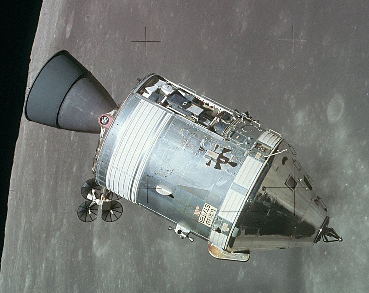
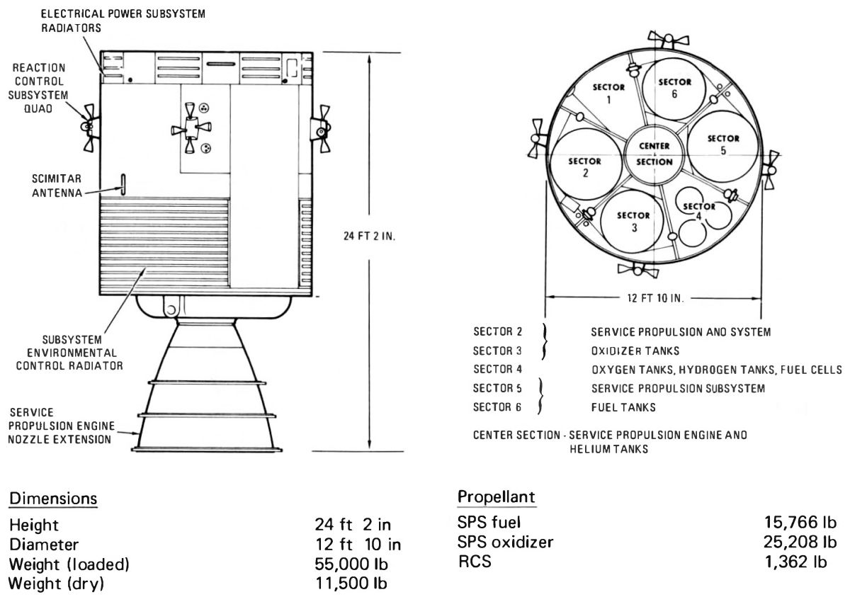
The cylindrical service Module (SM) housed critical systems and supplies used by the Apollo CM for almost an entire lunar mission. It provided propulsion, reaction control, electrical power, environmental control and telecommunications. The SM also supplied most consumables, including propellants, oxygen, hydrogen, water and electricity. It remained attached to the CM until just before earth atmospheric reentry, when it was jettisoned and subsequently destroyed by reentry heating and dynamic pressure. At 24 feet 2 inches long, 12 feet 10 inches in diameter and weighing 55,000 lb loaded, the SM was more than twice as long and more than four times as heavy as the CM. About 75%t of the SM's weight was SPS propellant. |
SM Organization
The SM consisted of a circular center section surrounded by six pie-shaped sectors. Structural components included forward and aft bulkheads, six radial beams, four sector honeycomb exterior panels, four reaction control system honeycomb exterior panels, an aft heat shield, and a fairing. The solid aluminum alloy radial beams were machined and chemically-milled to thicknesses that varied between 2" and 0.018", producing an efficient lightweight structure. Radial beam trusses extended above the forward bulkhead supported and secured the command module. Three of these beams had compression pads and the other three had shear-compression pads and tension ties. Explosive charges in the tension ties separated the CM and SM. An aft heat shield surrounding the service propulsion engine protected the SM from engine heat. The gap between the CM and SM forward bulkhead was closed off with a fairing that was 0.5" thick and 22" high. Eight electrical power system radiators alternating with eight aluminum honeycomb panels comprised the fairing. Major SM systems included service propulsion (SPS), reaction control (RCS), electrical power (EPS), environmental control (ECS) and telecommunications (TCS).
Maintenance doors around the SM exterior provided access to equipment within each sector. These doors, intended for installation and checkout operations, were not used during space operations. The 1" thick sector and reaction control system (RCS) panels were made of aluminum honeycomb core between two aluminum face sheets. The sector panels were bolted to the radial beams.
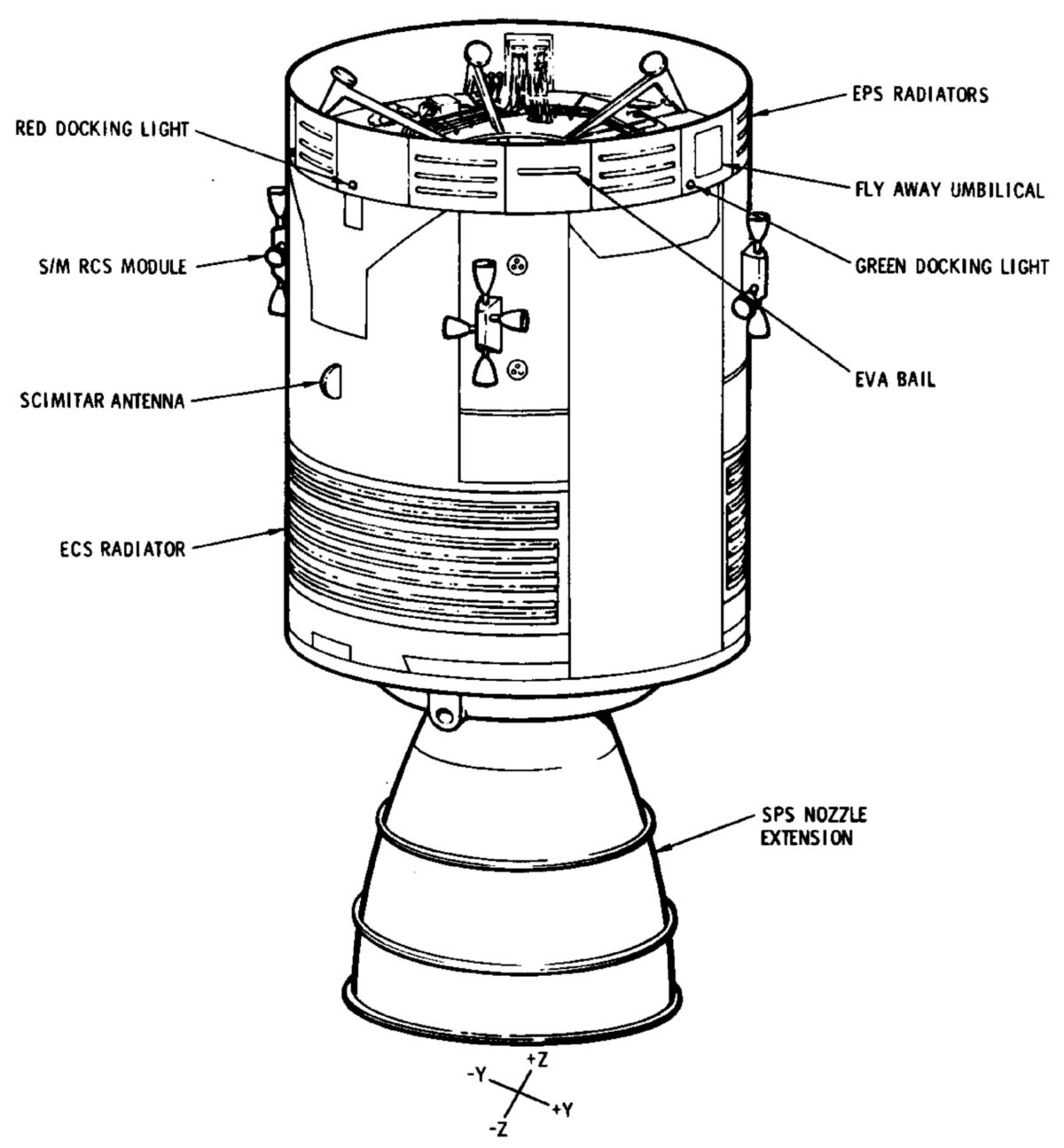
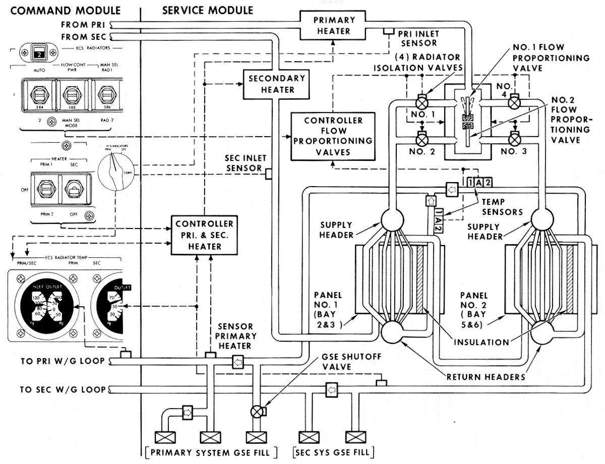
On the SM exterior were ECS and EPS space radiators, RCS engines, three antennas, umbilical connections, and several lights. Two large (30 ft²) ECS space radiators radiated CM cabin and equipment heat to the cold of space. They were bonded to sector panels on opposite sides of the SM lower half, one on the Sectors 2 and 3 panel covers and the other on the Sectors 5 and 6 panel covers. The radiators consisted of five parallel horizontal primary tubes and four parallel vertical secondary tubes through which a water-glycol coolant flowed. Both the primary and secondary coolant systems shared the same radiator surface.
Eight EPS space radiators, located on the fairing at the SM top, contained three tubes that radiated excess heat produced by the fuel cell powerplants into space. One of the three tubes on each panel was connected to a specific powerplant. Each radiator panels alternated with eight aluminum honeycomb panels.
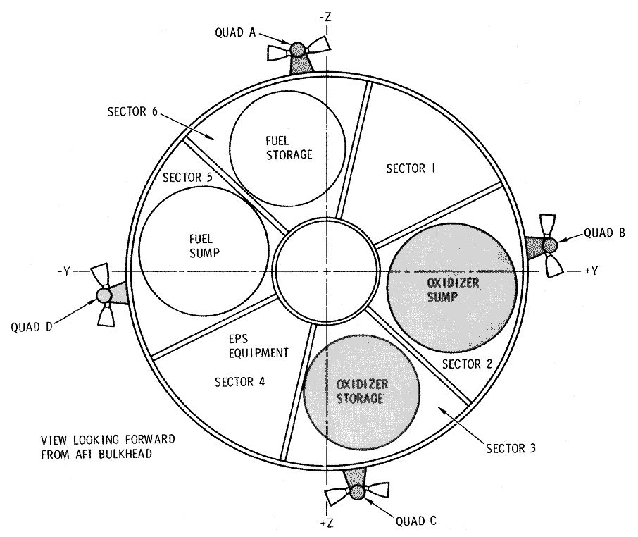
RCS engines were located in four clusters called quads spaced 90° apart around the upper SM. The engines were on the panel's outside while all other components were inside. Two quad engines pointed in opposite directions parallel with the spacecraft longitudinal axis and two pointed in opposite directions tangent to the SM's circumference. Quad interior components included two oxidizer tanks, two fuel tanks, a helium tank, along with associated valves, regulators, and plumbing. Each quad package was about eight feet long and nearly three feet wide.
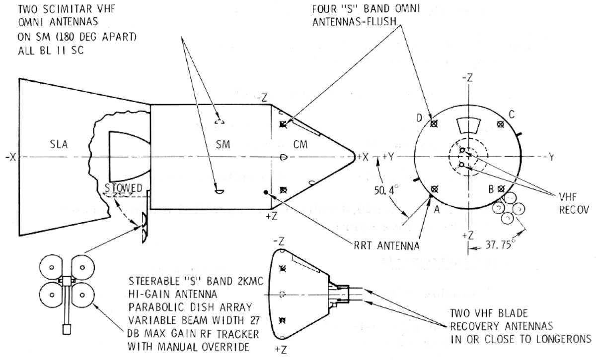
Four S-band high-gain antennas, mounted outside the SM aft bulkhead, were used for deep space communications. Each S-band antenna consisted of a 31" circular reflector surrounding an 11" square reflector. At launch, they were folded parallel to the SPS engine nozzle so that they fitted within the spacecraft-LM adapter (SLA). After the CSM separated from the SLA the antennas deployed at a right angle to the SM centerline. Two VHF omni-directional antennas, called scimitars because of their shape, were mounted on opposite sides near the SM top. Made of stainless steel they were about 13.5" long but very thin. A rendezvous radar transponder antenna was mounted in the SM fairing.
One umbilical, enclosed in an aluminum alloy fairing, housed plumbing and wiring connections between the CM and SM. Another "flyaway" umbilical, connected to the launch tower until launch, supplied GSE oxygen and nitrogen for cabin pressurization, water-glycol coolant, purge gas and electrical power.
Seven lights were mounted in the SM fairing panels . Four (one red, one green, and two amber) aided the docking process, one was a floodlight that illuminated extravehicular activities, one was a flashing beacon used to aid in rendezvous, and one was a spotlight used in rendezvous from 500 feet to docking.
The SM center section was 44" in diameter and contained two helium tanks at its top and center. The SPS engine was located in the center section lower half, with its nozzle extension protruding more than 9 feet below the SM aft bulkhead. The SPS was used as a retrorocket to brake the spacecraft from translunar flight and put it into lunar orbit, to send it homeward from the moon, and to correct the spacecraft's translunar and transearth trajectories.
The six SM sectors surrounded the center section were of unequal angles. Sectors 1 and 4 measured 50° of arc, Sectors 3 and 6 measured 60° of arc, and Sectors 2 and 5 measured 70° of arc. Sector 1 was reserved for equipment or scientific experiments contemplated for future lunar missions. It could also accommodate ballast to maintain the SM's center of gravity if no equipment was added. The Sector 2 exterior hosted a portion of a space radiator and an RCS quad (more about which later). Internally it contained the SPS oxidizer sump tank and plumbing, along with RCS quad tanks and plumbing. The Sector 3 exterior hosted the remainder of the space radiator and an RCS quad. Internally it contained the SPS oxidizer storage tank and its associated plumbing. Sector 4 contained most of the electrical power system, including three fuel cell powerplants, two cryogenic oxygen, two cryogenic hydrogen tanks, a power control relay box, and a helium servicing panel. The three fuel cell powerplants were mounted on a shelf in the sector's upper third. They supplied most of the spacecraft electrical power along with some of the drinking water. The cryogenic tanks supplied breathing oxygen to the environmental control system and oxygen and hydrogen to the fuel cell powerplants. The tanks were spheres, with the oxygen tanks mounted side by side in the center of the sector and the hydrogen tanks mounted below them one on top of the other. The power control relay box operated in conjunction with the fuel cell powerplants to control the generation and distribution of electrical power. The Sector 5 exterior hosted part of an ECS radiator and an RCS quad. Internally it contained the SPS fuel sump tank, which occupied nearly all of the sector's volume. The Sector 6 exterior hosted the rest of the ECS radiator and an RCS quad; internally it contained the fuel storage tank. Although the fuel and oxidizer sump and storage tanks were the same size, they differed in weight as the oxidizer was more than 50% heavier than the fuel.
 |
 |
 |
 |
 |
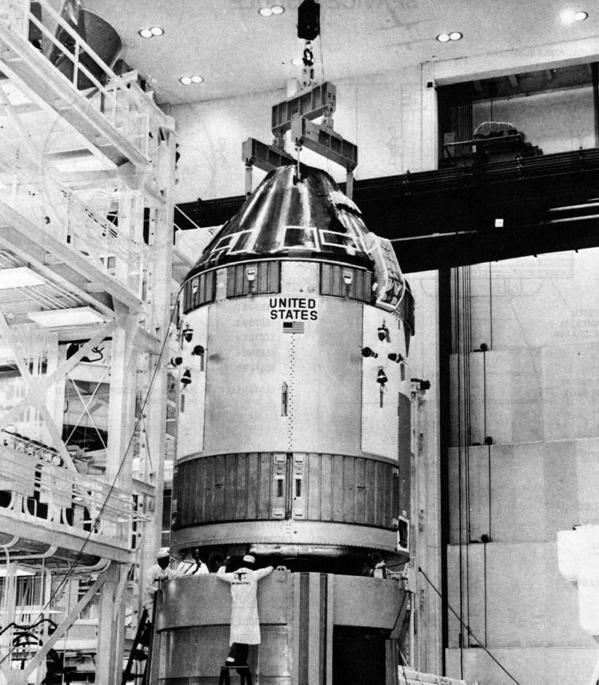
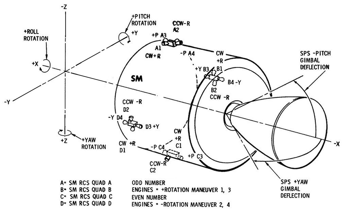
| Command Module Mating | Overview | Interior Organization | Orientation and Thrust Generators | Exterior Detail |
Service Propulsion System (SPS)
 |
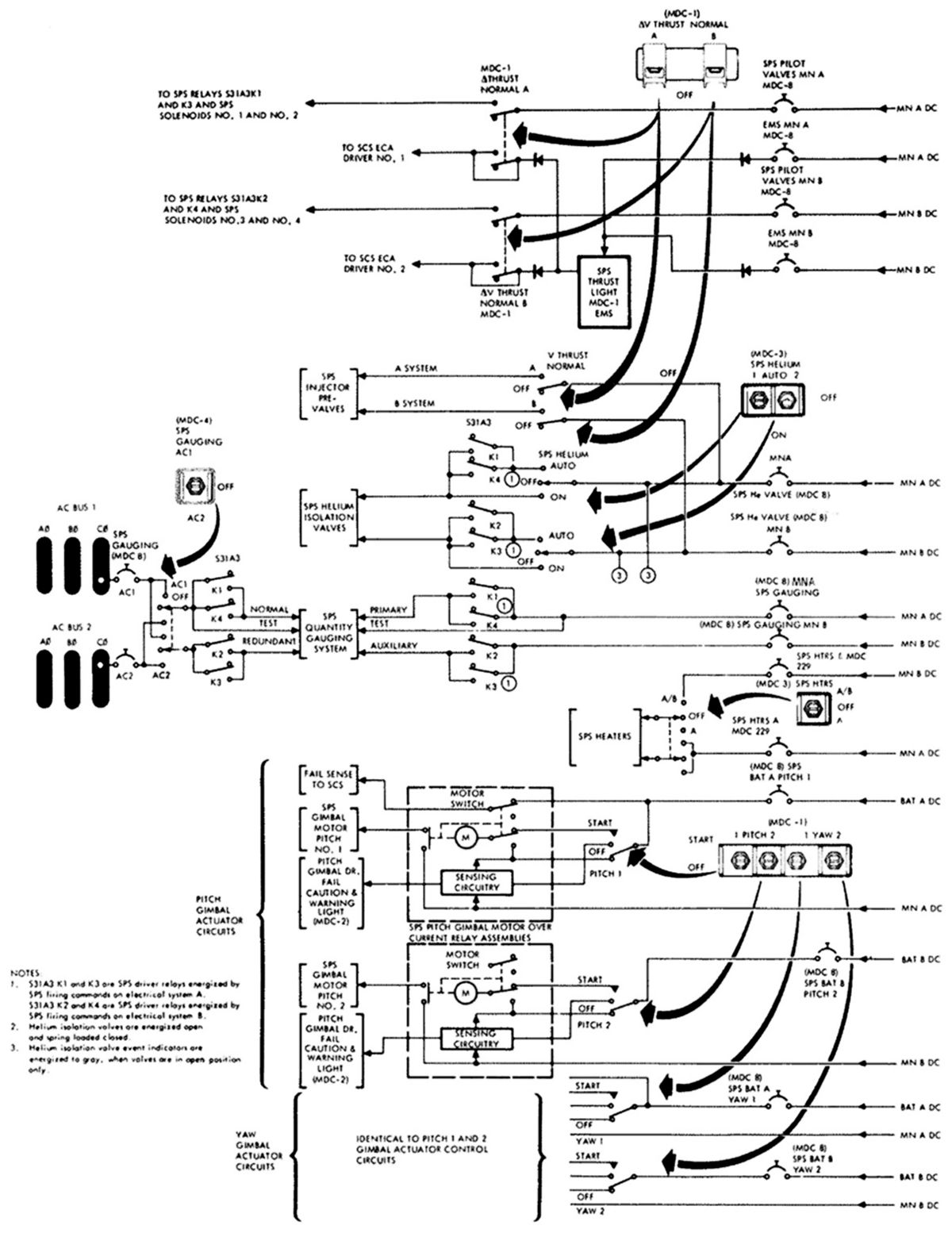 |
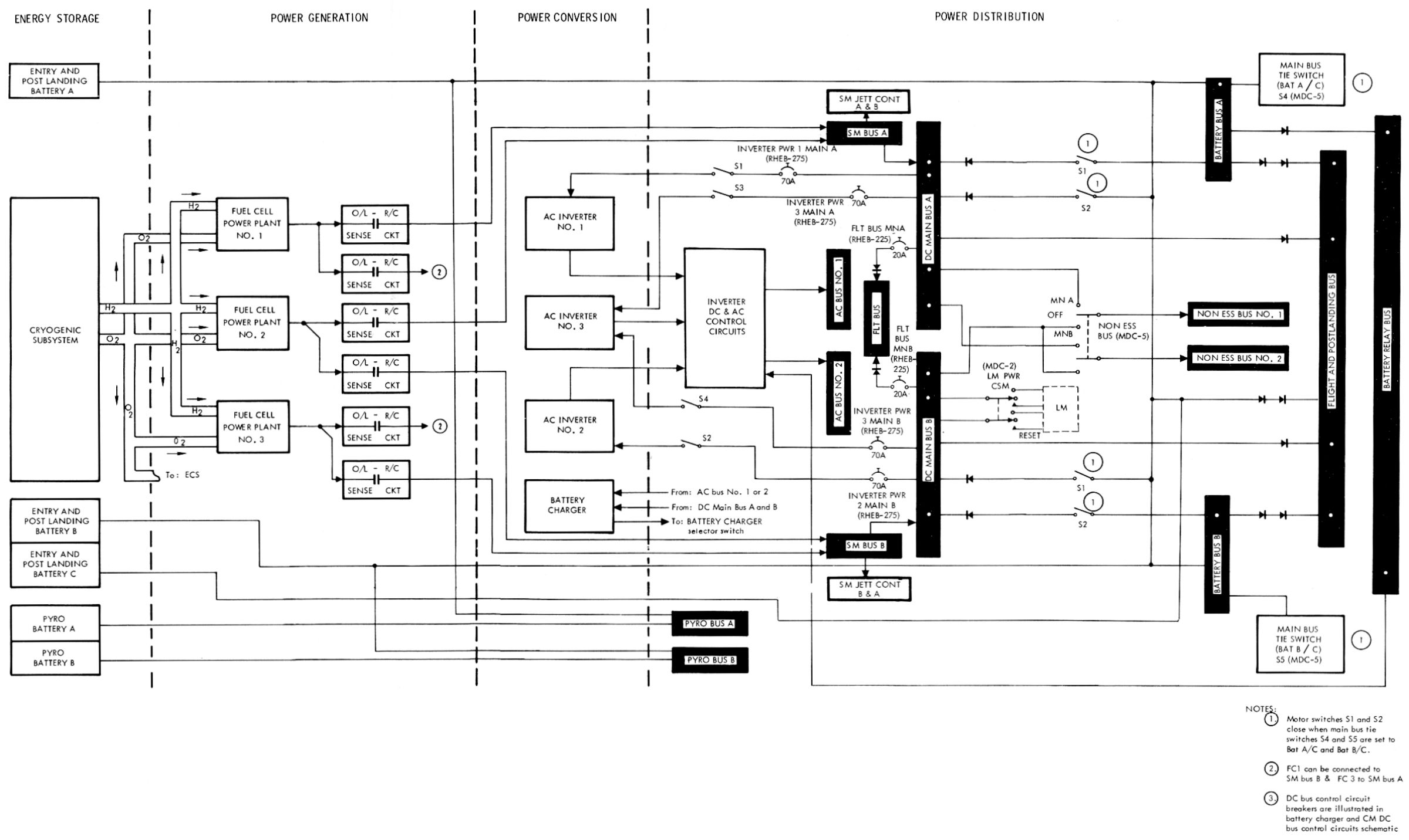
| System Schematic | Distribution |
Electrical Power System (EPS)
The EPS supplied electrical power for all command and service module (CSM) functions, as well as to the lunar module (LM) for heater circuits after transposition and docking. The EPS was functionally divided into energy storage via cryogenics and batteries, power generation using fuel cell power plants, power conversion using solid state inverters, and power distribution to DC and AC power buses, DC and AC sensing circuits, controls and displays.
The primary EPS energy source was the cryogenic gas storage system that provided fuel (H2) and oxidizer (O2) to the power generating system. Two hydrogen and two oxygen tanks, with the associated controls and plumbing, were located in the service module. The system was automatically or manually controlled. Five silver oxide-zinc batteries located in the CM furnished a secondary energy source.
Power Generation and Conversion
Three Bacon-type fuel cell power plants, which generated electricity through electrochemical reaction of H2 and O2, supplied primary DC power to spacecraft systems via two redundant DC buses until CSM separation. Each power plant could nominally supply from 400 to 1,420 watts at 31 to 27 VDC to the power distribution bus system. All three power plants normally generated power, but two were sufficient for mission completion and one was adequate if loads were reduced.
Primary DC power was converted into AC by three solid state static inverters that each provided 115/200-volt 400-Hz 3-phase AC power at up to 1,250 volt-amperes to two redundant AC buses. One inverter could supplying all spacecraft primary AC power. A battery charger powered by the primary DC and AC buses kept the CM reentry and postlanding batteries fully charged state.
Lunar module power was furnished via two umbilicals that were manually connected after transposition, docking and extraction. An average of 81 watts DC powered continuous heaters in the LM abort sensor assembly (ASA), and cycling heaters in the landing radar, rendezvous radar, S-band antenna and inertial measurement unit (IMU). Power consumption with all heaters operating simultaneously was approximately 309 watts. LM floodlighting was also powered through the umbilical for use during manned lunar module operation while docked with the CSM.
 |
 |
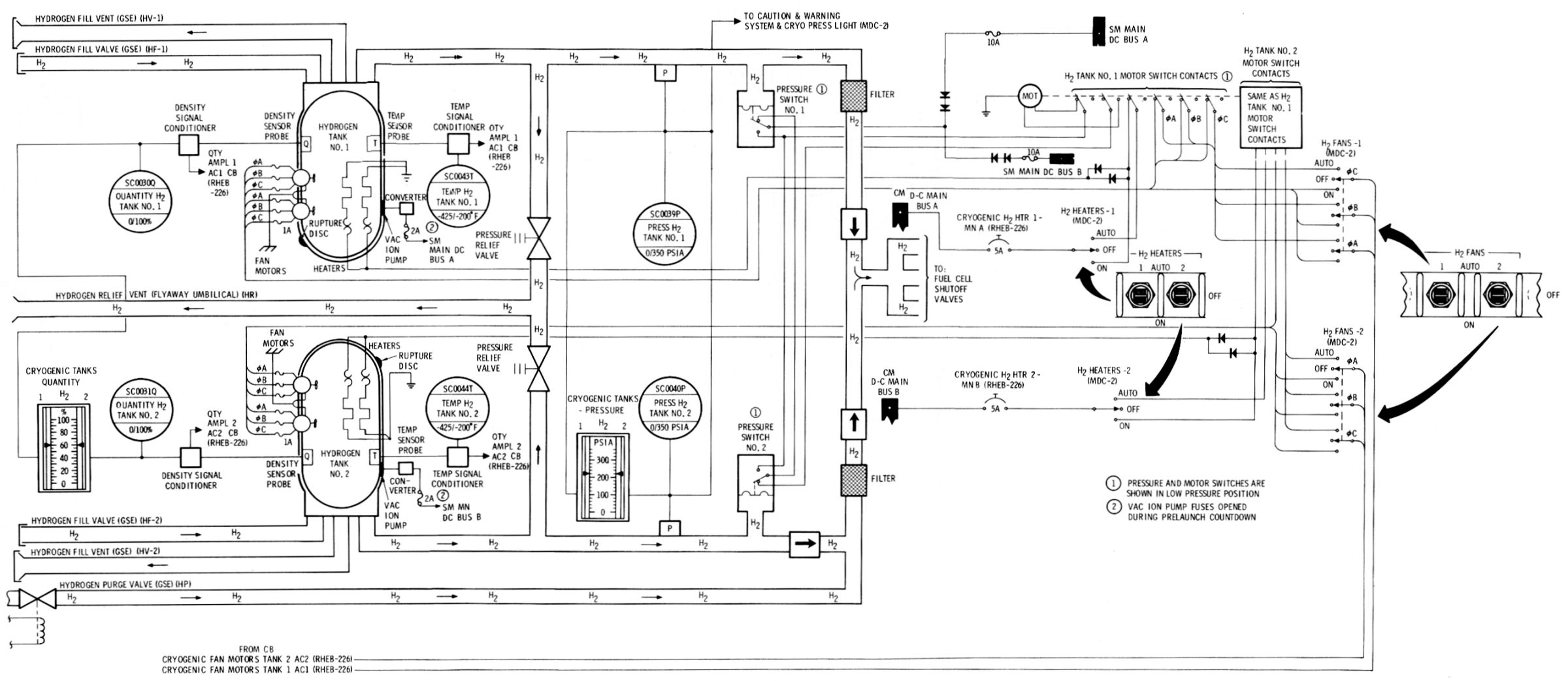
| Cryogenic Storage Schematic (Hydrogen, Oxygen Similar) |
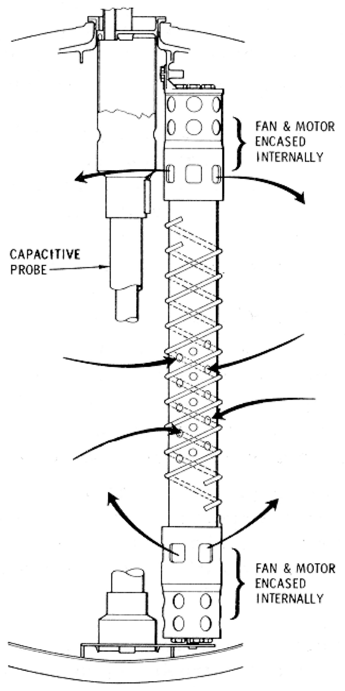
Pressurization and Quantity Measurement |
Cryogenic Storage
The cryogenic storage subsystem supplied hydrogen to the EPS, and oxygen to the EPS, ECS and for initial LM pressurization. The two hydrogen and oxygen subsystem tanks were large enough to provided a safe return from the furthest mission point using fluid remaining in any one tank. The Inconel oxygen tanks, built by Beech Aircraft of Boulder, Colorado were 26" in diameter and each held 326 lb. Oxygen tank temperatures ranged from -300°F to +80°F. The oxygen was a liquid when at or below -297°F. The titanium hydrogen tanks, built by Air Products & Chemical Co., Inc. of Allentown, Pennsylvania, were 31.75" in diameter and each held about 29 lb. Hydrogen tank operating temperature ranged from -425° F to +80°F. The hydrogen was a liquid when at or below -423°F.
GSE provided initial pressurization from fill to operating pressures after which the cryogenic fluids were at their triple point, a combination of temperature and pressure at which the fluids' gaseous, liquid and solid states existed in equilibrium. This single-phase, homogeneous condition avoided sloshing that could cause sudden pressure fluctuations and possible damage to internal components, and promoted positive mass quantity gauging. The single-phase expulsion process continued at nearly constant pressure and increasing temperature above the two-phase region. Two parallel DC heaters in each tank supplied the heat necessary to maintain design pressures. Two parallel 3-phase AC fans circulated the fluid over heating elements to maintain uniform density and combat stratification. Relief valves provided overpressure relief, check valves provided tank isolation, individual fuel cell shutoff valves provided isolation of malfunctioning power plants, and filters blocked particles, protecting the EPS and ECS components. Pressure transducers and temperature probes indicated fluid thermodynamic state. A capacitive quantity probe indicated fluid quantity. System repressurization was automatic or manual, controlled by switch selection. The automatic mode produced a single-phase reactant flow into the fuel cell and ECS feed lines at design pressures. The heaters and fans were automatically controlled through a pressure switch-motor switch arrangement. As pressure in the tanks decreased, the pressure switch in each tank closed to energize the motor switch, closing contacts in the heater and fan circuits. Both tanks had to decrease pressure before heater and fan circuits were energized. When either tank reached the upper operating pressure limit, that respective pressure switch opened to again energize the motor switch, thus opening the heater and fan circuits to both tanks. The O2 tank circuits were energized at 865 psia minimum and de-energized at 935 psia maximum. The H2 circuits energize at 225 psia minimum and de-energize at 260 psia maximum, The most accurate quantity readout was appeared shortly after the fans stopped. During all other periods partial stratification might degrade quantity readout accuracy.
When the systems reached the point where heater and fan cycling was at a minimum (due to a reduced heat requirement), the heat leak of the tank was sufficient to maintain design pressures provided flow was within the minimum change in heat versus change in mass (dQ/dm) value. This operation realm was referred to as the minimum dQ/dm region. The minimum heat requirement region for oxygen started at approximately 45% tank quantity and terminated at approximately 25%. Between these tank quantities, minimum heater and fan cycling occurred under normal usage. The heat required for repressurization at quantities below 25% started to increase until below the 3% level practically continuous heater and fan operation was required. In the hydrogen system, the quantity levels for minimum heater and fan cycling were between approximately 53% and 33%, with continuous operation occurring at approximately 5%.
Assuming a constant level flow from each tank (O2 = 1 lb/hr, H2 = 0.09 lb/hr) each successive repressurization period was of longer duration. The periods between repressurizations lengthened as quantity decreased from full to the minimum dq/dm level, and become shorter as quantities decreases from the minimum dq/dm level to the residual level. The maximum continuous flow that each cyrogenic tank provided at minimum design pressure was dependent on the quantity level and the heat required to maintain that pressure, which decreased from full to the minimum dq/dm point. As quantity decreased beyond the minimum dq/dm region, the heat required to maintain a constant pressure increased. As fluid was withdrawn, a specific amount of heat was also withdrawn. When the withdrawal rate exceeded the heat available from the heaters, fan motors, and heat leak, there was a resultant pressure decrease below the minimum design operating level.
Five silver oxide-zinc storage batteries were located in the CM lower equipment bay. Three rechargeable reentry and postlanding batteries powered CM systems after CSM separation and during postlanding. Prior to CSM separation, the batteries provided a secondary source of power while the fuel cells were the primary source.2.6.3.3. 1
 |
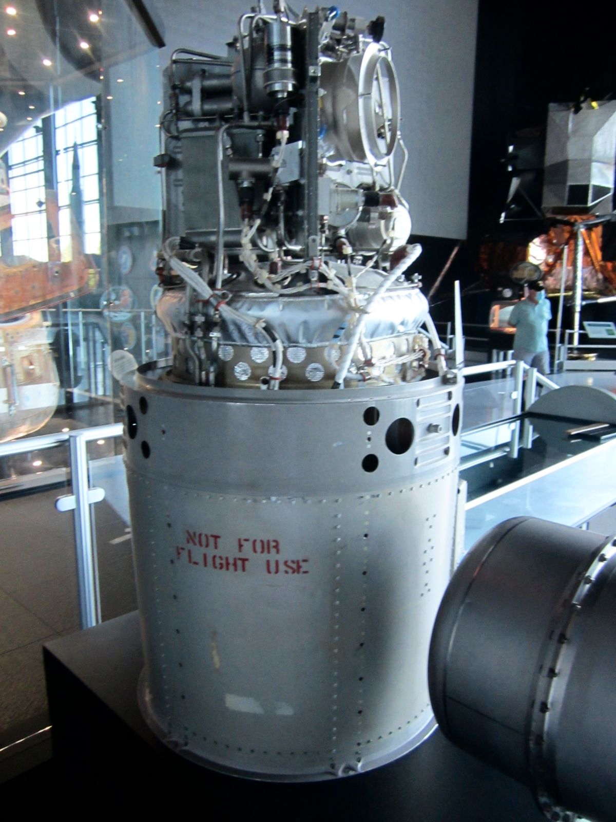 |
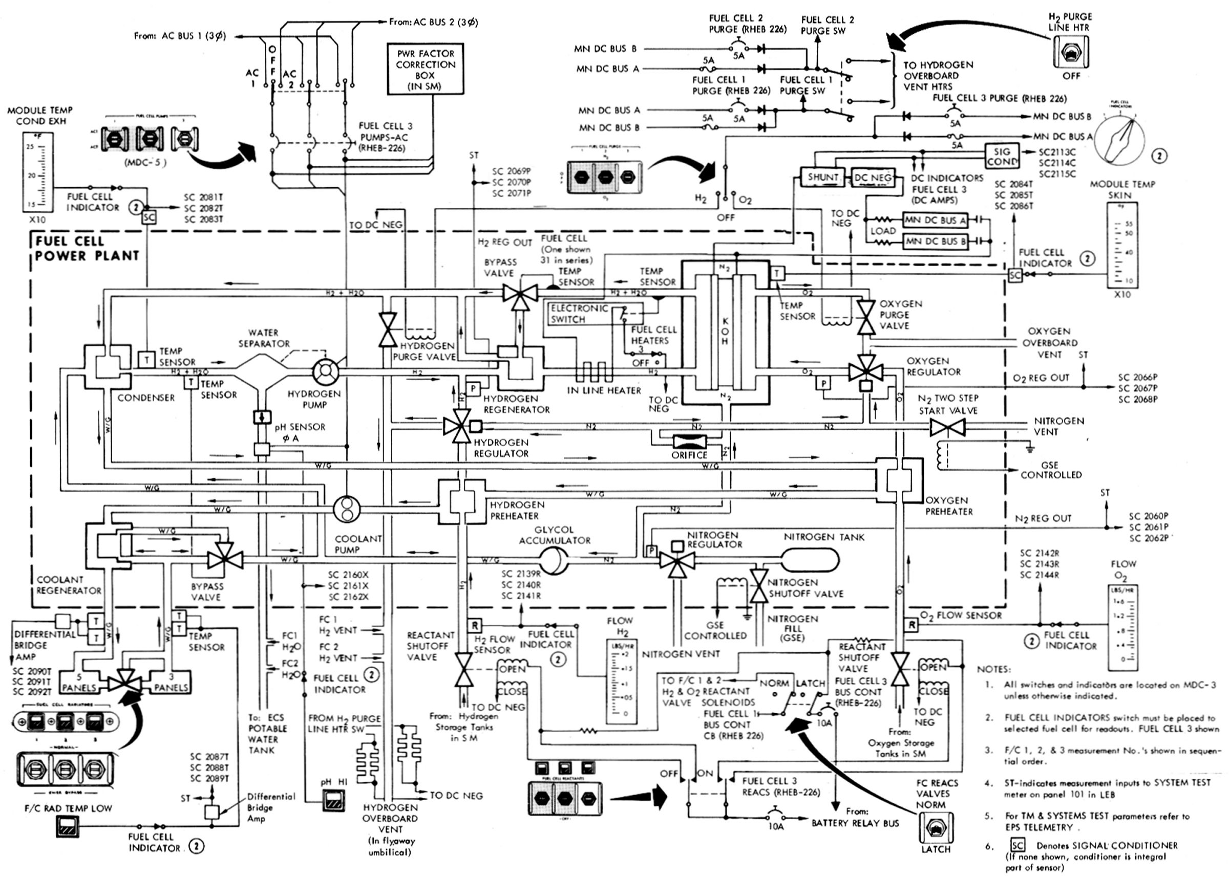
| Schematic | Exterior |
The fuel cell powerplants, built by Pratt & Whitney Aircraft of Hartford, Connecticut were 44" high, 22" in diameter, and weighed about 245 lb. Each power plant consisted of 31 single cells connected in series and enclosed in a metal pressure jacket. The water separation, reactant control, and heat transfer components were mounted in a compact accessory section attached directly above the pressure jacket. The primary (hydrogen) and secondary (glycol) loops controlled power plant temperature. A continuously-operating hydrogen pump removed water vapor and heat from the cell stack. The primary bypass valve regulated flow through the hydrogen regenerator to transfer exhaust heat to incoming hydrogen gas. Flow was a function of skin temperature. The exhaust gas flowed to the condenser where waste heat was transferred to the glycol and some of the water vapor liquefied. A motor-driven centrifugal water separator extracted liquid water and fed it to the CM potable water tank. The cooled gas was then pumped back to the fuel cell through the primary regenerator by a motor-driven vane pump, which also compensated for pressure losses due to water extraction and cooling. Waste heat was transferred to the condenser coolant and then to radiators located on the fairing between the CM and SM, where it was radiated into space.
N2 gas at 1,500 psia was stored in each power plant and regulated to a pressure of 53 ± 3 psia. Regulated N2 pressurized the electrolyte in each cell, the coolant loop through an accumulator, and was coupled to the O2 and H2 regulators as a reference pressure.
LOX, supplied to the power plants at 900 ± 35 psia, after absorbed heat from the distribution lines and preheater, reached the oxygen regulator as a gas at temperatures above 100°F. The differential regulator reduced oxygen pressure to 9.5 psia above the N2 reference, nominally supplying it to the fuel cell stack at 62.5 ± 2 psia, Within the porous oxygen electrodes, the O2 reacted with H2O in the electrolyte and electrons from an external circuit to produce hydroxyl ions (O2 + 2 H2O + 4 e = 4 OH-). LH2, supplied to the power plants at 245 (+15, -20) psia, was similarly heated, arriving at the hydrogen regulator as a gas. The differential hydrogen regulator reduced the pressure to 8.5 psia above the reference N2, thus supplying it in a gaseous form to the fuel cells at 61.5±2 psia, The hydrogen reacted in the porous hydrogen electrodes with the hydroxyl ions in the electrolyte to produce electrons, water vapor, and heat (2 H2 + 4 OH- = 4 H2O + 4 e + heat).
Each power plant cell contained electrolyte consisting of 83% potassium hydroxide (KOH) and 17% water by weight. During normal operation, water content varied between 23% and 28%. At this ratio, the electrolyte had a critical temperature of 300°F. It solidified at about 220°F. Power plant electrochemical reaction became effective at the critical temperature. Bringing power plants to critical temperature was performed by GSE and could not be performed from SC power sources. Placing a load on the power plant maintained it above the critical temperature. The automatic in-line heater circuit maintained power plant temperature at 385°F with no additional loads applied.
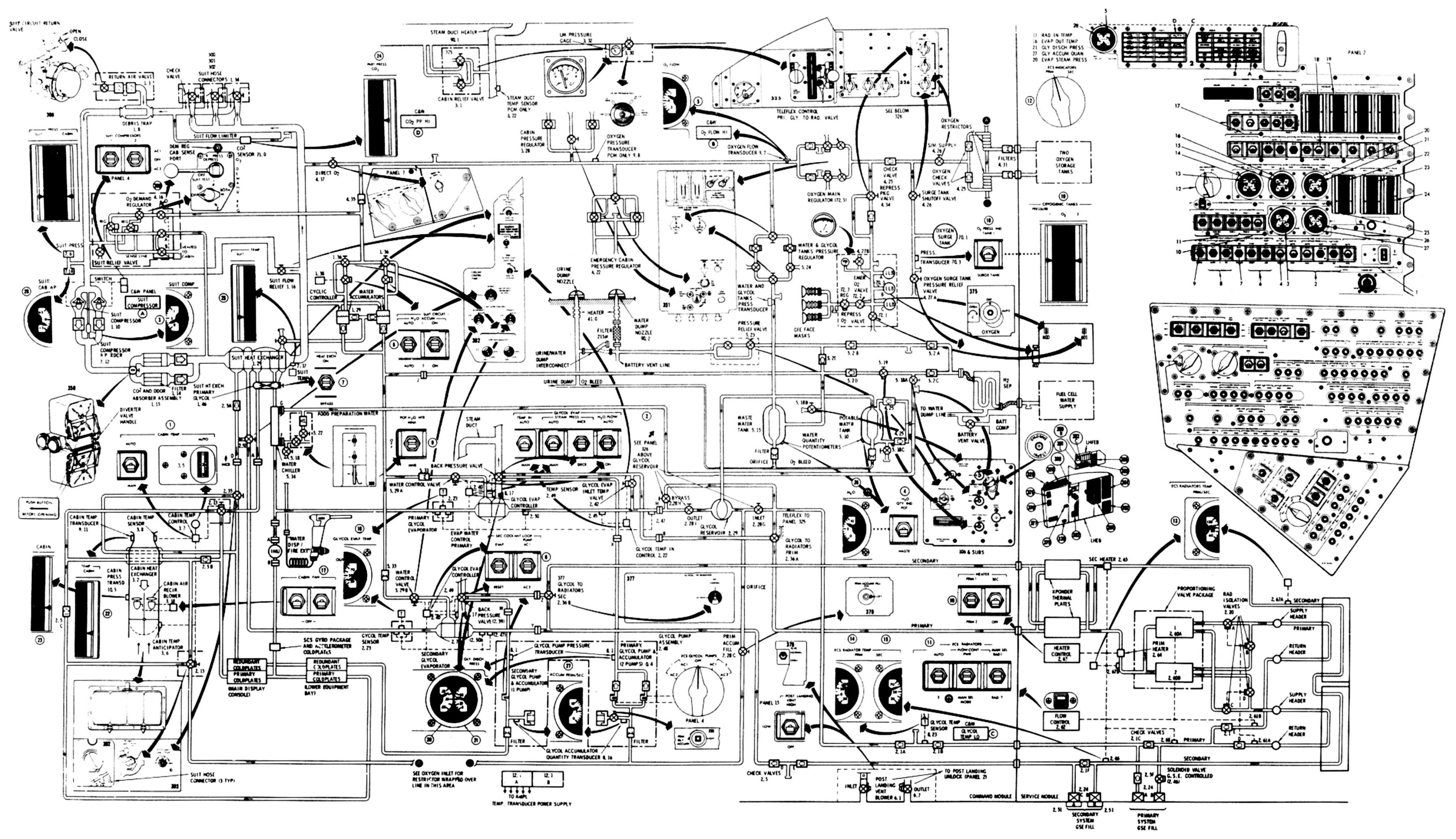
Environmental Control System (ECS)
The ECS provided the flight crew with a life-supporting conditioned environment that was as comfortable as possible. It interfaced with the electrical power system, which supplied oxygen and potable water. The ECS also provided thermal control for several CM electronic components and helped pressurize the lunar module (LM). The ECS operated continuously throughout all Apollo mission phases, furnishing spacecraft atmosphere control, water management and thermal control.
Spacecraft atmosphere control involved regulating the pressure and temperature of the cabin and suit gases, maintaining the desired humidity by removing excess water from the suit and cabin gases; controlling the level of contamination of the gases by removing CO2, odors, and particulate matter; and ventilating the cabin after landing. The ECS provided a means for pressurizing the lunar module during docking and subsequent CSM/LM operations.
Water management involved collecting, sterilizing, and storing potable water produced in the fuel cells, delivering chilled and heated water to the crew for metabolic consumption, and disposing of excess potable water by either transferring it to the waste water system or by dumping it overboard. The ECS also collected and stored waste water extracted during humidity control, delivering it to the glycol evaporators for supplemental cooling, and dumping the excess overboard.
Thermal control consisted of removing the excess heat generated by the crew and the spacecraft equipment and it to space either by the space radiators or as steam from boiling water in the glycol evaporators.
 |
 |
 |
 |
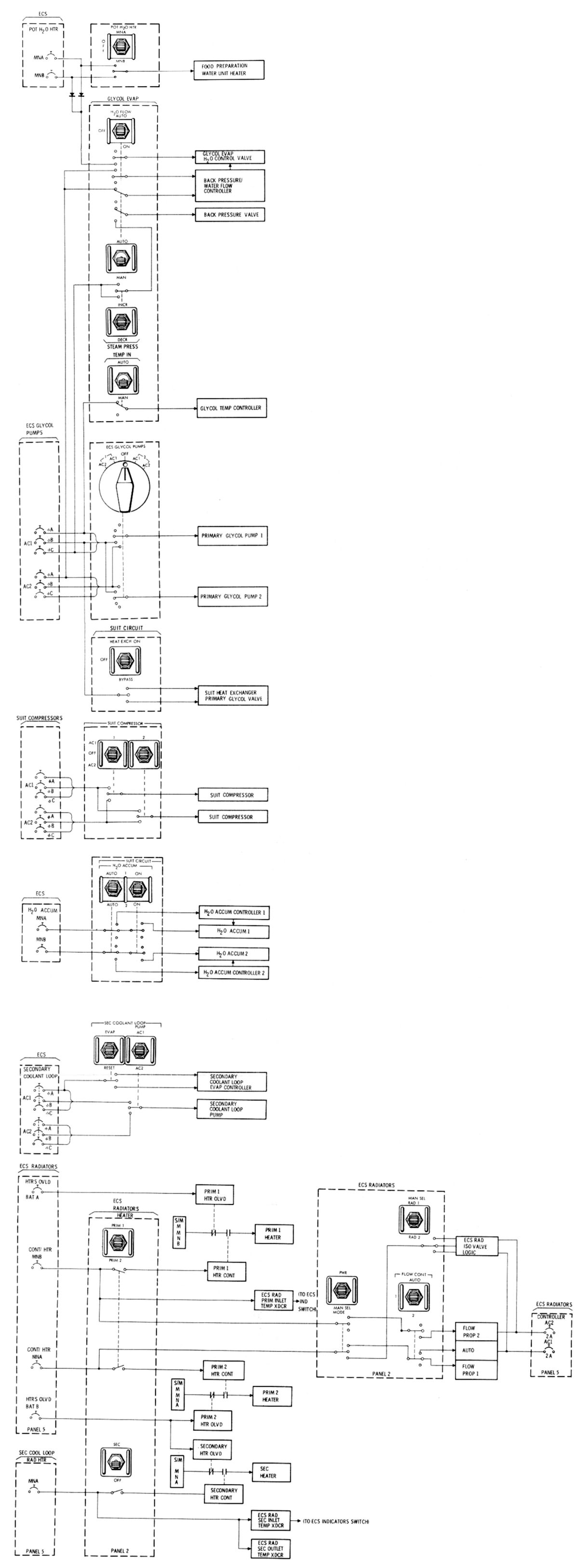 |
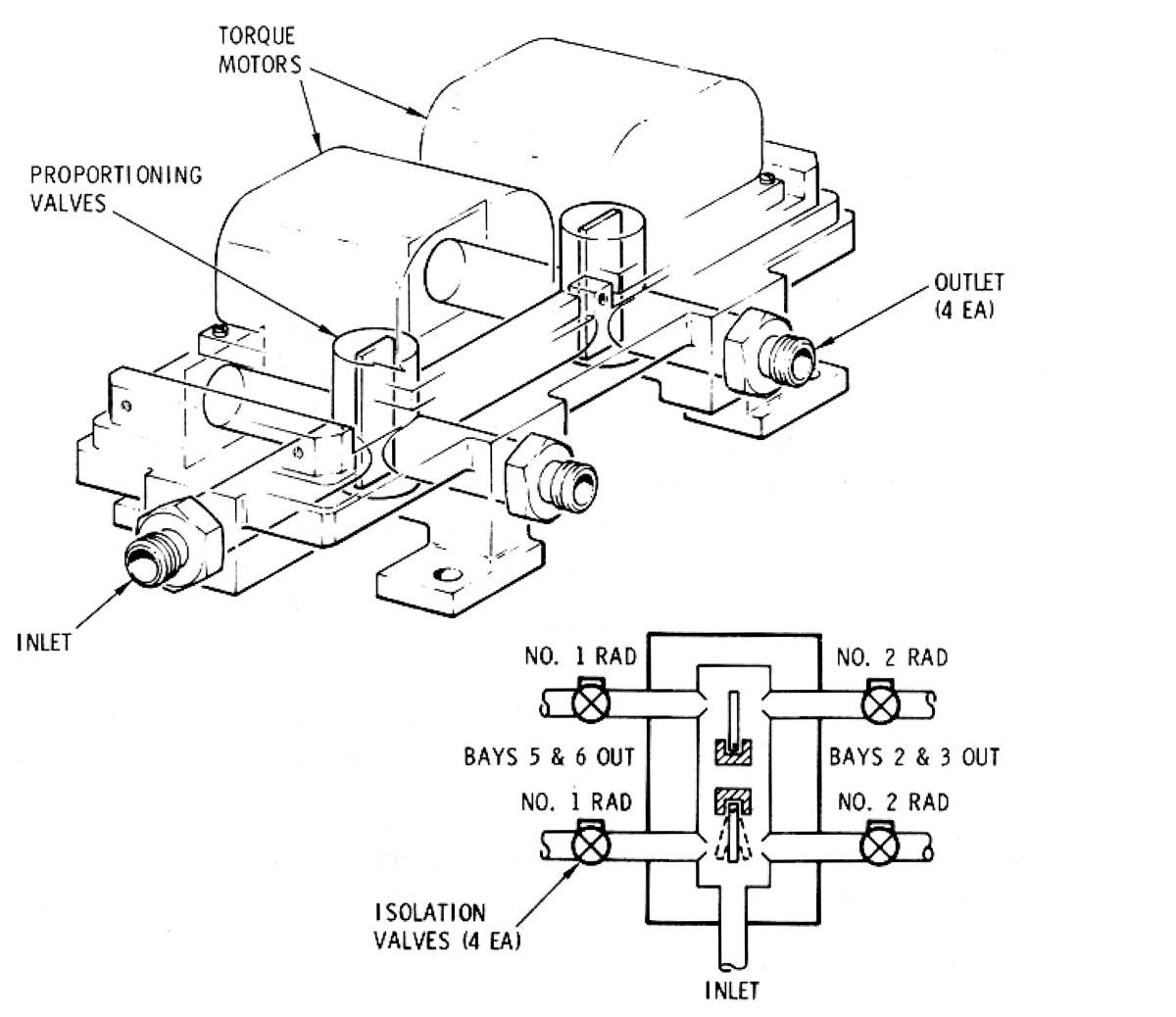
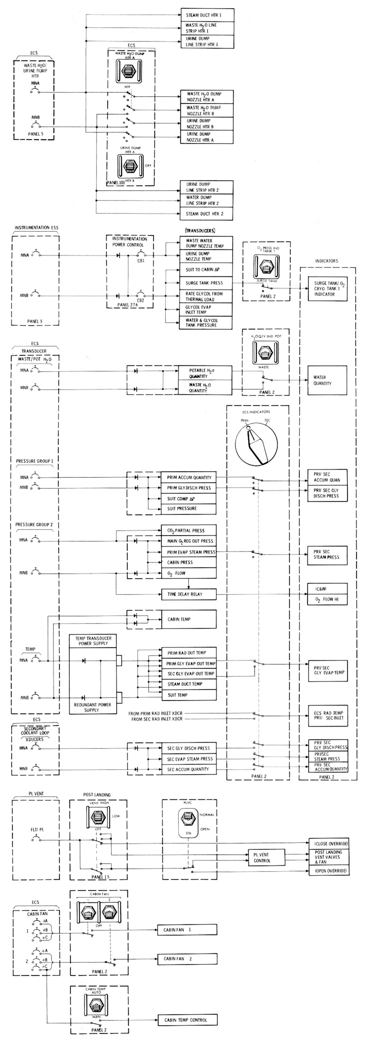
| System Schematic | Radiator Subsystem | Space Radiator Flow Proportioning Valve | Power Distribution | |
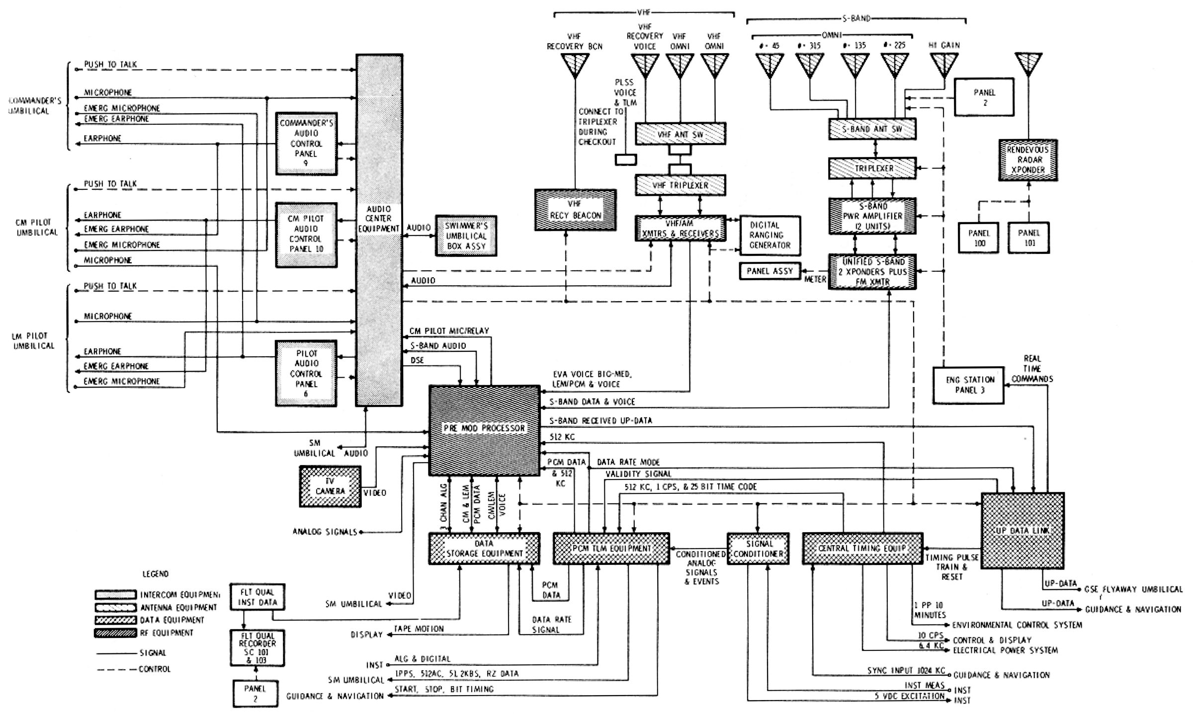
Telecommunications System (TCS)
The TCS links the spacecraft and manned space flight network (MSFN), providing voice communication and data to MSFN flight controllers, which allows them to monitor spacecraft parameters, system status, crew biomedical data, event occurrence, and scientific data. The TCS also furnishes the primary means for the determining spacecraft position and rate of change. A ranging transponder and active ranging system facilitates CM-LM rendezvous. Direction finding aids allow postlanding location and rescue by ground personnel.
 |
 |
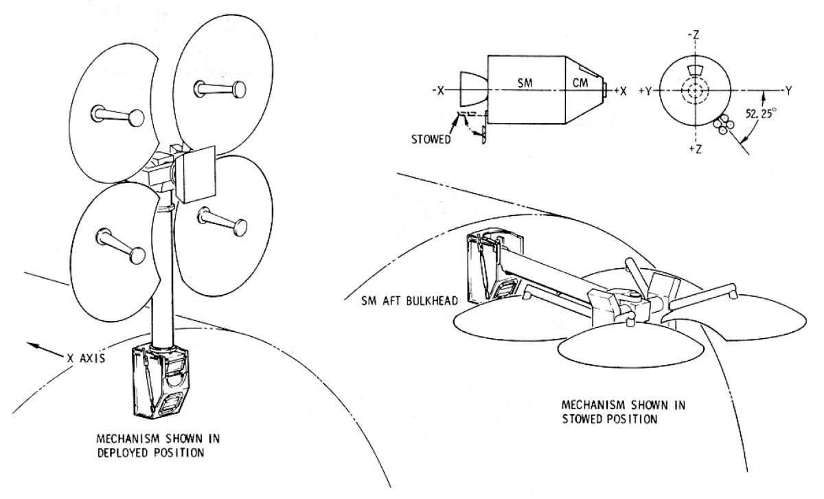 |
| System Schematic | Antenna Locations | High-Gain Antenna Detail |
SM-CM Separation
Separation of the SM from the CM occurred shortly before reentry. The separation event sequence was controlled automatically by two redundant service module jettison controllers, located on the forward SM bulkhead. A number of events occurred either simultaneously or in rapid sequence. These included physical separation of all the connections between the modules, transfer of electrical control, and firing of the SM's RCS engines to increase the distance between the modules. Before separation, the crew transferred electrical control to the CM RCS, pressurized it and checked its functionality for reentry maneuvers. The SM RCS had been used for maneuvering up to that point. Electrical control was then transferred back to the SM RCS. Separation was started manually by actuating either of two redundant switches on the main display console (MDC). These switches signaled the SM jettison controllers, which fired ordnance to activate the CM-SM electrical circuit interrupters that cut off all power to electrical wires in the CM-SM umbilical. One-tenth a second later the controllers fired ordnance that severed three tension ties and the umbilical, physically disconnecting the CM and SM. Simultaneously the controllers fired the SM RCS roll engines for 5 seconds and the translation (thrust) engines continuously until the propellant was depleted or fuel cell powerplant power was expended. These maneuvers carried the SM well away from the CM's reentry path. Meanwhile the SM entered the earth's atmosphere and burned up.
References
Apollo Operations Handbook, Block II Spacecraft Volume 1, Spacecraft Description SM2A-03-BLOCK II-(1) (Houston, Texas: NASA Spacecraft Systems Operation Branch, Flight Crew Support Division, 15 Oct 1969).
Apollo Spacecraft News Reference (Downey, California: Space Division, North American Rockwell, 1969).
Fisher, Steven C. and Shamin A. Rahman, eds. Remembering the Giants: Apollo Rocket Propulsion Development (Washington, DC: NASA, 2009).
--- On to Part 9.40, The Apollo Lunar Module ---
Send mail to
![]() with questions or comments about this web site.
with questions or comments about this web site.
![]()