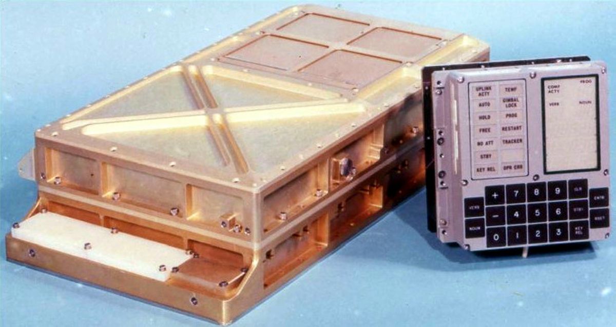
Apollo Guidance Computer, Block II (NASA)
U.S. Manned Rocket Propulsion Evolution
Part 9.50: The Apollo Guidance Computer
Compiled by Kimble D. McCutcheon
Published 29 Dec 2022; Revised 18 Jan 2023
Apollo Guidance Computer, Block II (NASA) |
Technological advances made during Project Apollo form the foundation of our modern world. Advances in material science, rocket engines, production and management are almost too numerous to count. However, chief among the technological advances was the Massachusetts Institute of Technology Instrumentation Laboratory (MIT/IL) Apollo Guidance Computer, which was used to navigate from the earth to the moon and back. This computer implemented the first digital fly-by-wire flight control system, the first digital autopilot and the first general purpose computer built of digital integrated circuits. The U.S. military, not NASA, instigated integrated circuit development. But it was NASA that purchased over a million integrated circuits for the Apollo Guidance Computer project, an action that kick-started the U.S. semiconductor industry and made integrated circuits cheap enough for nearly anyone to afford. Today, one is hard-pressed to touch anything in our lives that does not trace its lineage back to the Apollo Guidance Computer, a little box that quite literally changed the world. |
1.0 Overview
At least twenty-two AGCs flew and another twenty-five were used in prelaunch activities including system checkout, spacecraft checkout and simulation.
2.0 Hardware History
Eldon Conrad Hall (15 Jun 1923 – 25 May 2022) led the Apollo computer design team with help from MIT/IL members Dr. Raymond Alonso, Dr. Albert Hopkins, and Hugh Blair-Smith. They were supported by Raytheon engineers who worked with Hall on the Navy UGM-27 Polaris submarine-launched ballistic missile guidance system. The Polaris guidance system comprised a wired-program digital differential analyzer, welded cordwood modular packaging, machine-applied wire-wrap backplane interconnects, and 12 x 17-bit magnetic-core shift registers, all of which were ground breaking when they first flew in 1959.
| Core-Transistor Logic |
Starting in 1958, NASA contracted the MIT/IL to study guidance, navigation and control issues for several planetary missions, including a Mars photographic flyby and return to Earth. This study produced a preliminary design for a light-weight, low-power control computer with a small random-access memory and read-only memory for program and constant storage. Core-transistor logic circuits were selected due to their low power consumption and ability to operate at very slow speeds; the computer could change its own clock rate to save power. This computer could be interrupted and memory cycles could be stolen to increment or shift a memory location when processing input data. The Mars computer also introduced interpretive instructions and a large subroutine library, which enhanced the limited native instruction set by providing a uniform way of implementing complex high-level instructions. This reduced the number of logic circuits that would have been required without the interpreted instructions. A 16-bit word length (14 data, 1 sign, 1 parity) was adequate for most control and arithmetic, while 28 bit double-precision operations gave sufficient navigational accuracy. Lithium ferrite memory core progress resulted in memory elements with low temperature coefficients, which the computer used in a 3-dimensional coincident-current magnetic core array for its random access memory.
| Double Precision | ||||
|---|---|---|---|---|
| Scalar Arithmetic | Scalar Functions | Vector Arithmetic | Decision Operations | Indexing Operations |
| Add | Square Root | Add | Branch Positive | Load Index Directly |
| Subtract | Sine | Subtract | Branch Negative | Load Index Indirectly |
| Subtract From | Cosine | Subtract From | Branch Zero | Store Index |
| Multiply | Sin-1 | Vector Times Scalar | Branch It Overflow | Exchange Index |
| Multiply and Round | Cosine-1 | Dot Product | Add to Index | |
| Divide By | Absolute Value | Cross Product | Subtract from Index | |
| Divide Into | Complement | Matrix Pre-Multiply | Count on Index | |
| Shifting | Matrix Post-Multiply | |||
| Normalization | Unit Operation | |||
| Vector Magnitude | ||||
| Vector Complement | ||||
| Shifting | ||||
Semiconductor technology was also rapidly evolving; germanium transistors gave way to silicon transistors, then planar silicon transistors, followed by epitaxial discrete devices, and finally monolithic integrated circuits, whose packages were extremely small, reducing hardware weight and volume.
The Mars computer was never built, but when NASA approached the MIT/IL about the Apollo computer project, the Mars computer design formed its basis. Designers strove to design a reliable computer with sufficient capacity and speed yet with a very limited size, weight, and power drain. The proposed Apollo computer was also a 16 bit, parallel, general purpose, real-time digital control computer initially configured with magnetic core-transistor logic. The fixed memory was high density read-only core-rope memory developed in connection with the Mars probe. This meant that the fixed memory contents had to be determined early in order to allow time for manufacture. Rather than a disadvantage, risky last-minute changes of the program just before flight were physically prevented. A rope memory program was necessarily well tested before it flew on an Apollo mission.
A Mod 1A prototype breadboard was followed by Mod 1B and Mod 3C breadboards. All used core-rope fixed memory and magnetic-core logic. Program interrupts (a new concept) accommodated external events. Specialized input/output circuits processing voltages, pulse trains, and discrete input/output (I/O) facilitated communication with all CM and LM controls and sensors.
Unlike the Mars computer, the Apollo computer required an input/output device with which the astronaut could communicate with the computer . This was a new requirement for a control computer and the subject of protracted debate. A display/keyboard (DSKY) was designed to meet the interactive needs.
By November 1962 the Mod 3C had evolved to become the AGC3, the first breadboard Apollo computer. It consisted of six refrigerator-sized cabinets housing core-rope fixed memory, coincident-current core erasable memory, and core-transistor logic. The MIT/IL team worked to reduce its size by using the welded-cordwood modular packaging techniques it had pioneered during the Polaris guidance system program.
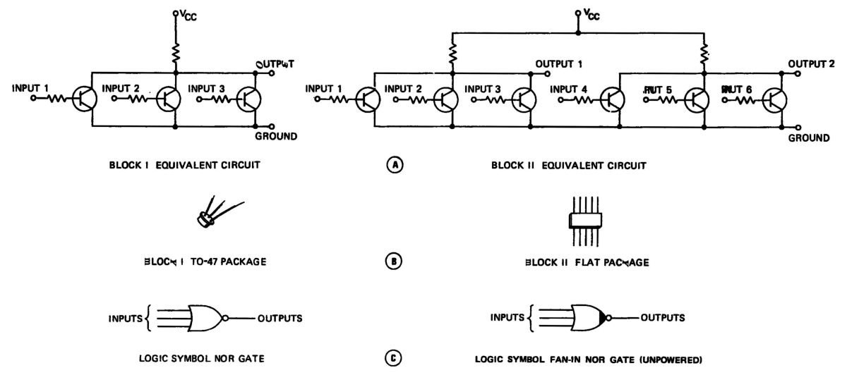
During the time between the Mars study and the AGC3, the electronics industry had begun producing its first integrated circuits (ICs). Starting on 4 Jan 1962 the MIT/IL began evaluating the reliability, power consumption, and noise characteristic of these new ICs. This technology promised to further reduce the Apollo computer's size, weight and power consumption. A 3-input NOR gate in a TO-47 package (about the size of a baby aspirin), part of the Fairchild Micrologic family, was selected as the sole logic element for as the basis for Apollo computer implementation.
This was a controversial choice, as the 4,100-IC count could have been reduced by using multiple IC types. However, a single IC type reduced the program's complication at every turn. Most importantly, the single IC type allowed engineers to rapidly quantify the IC's reliability, an important consideration for the overall Apollo computer reliability.
The AGC3 design team resisted changing the core-transistor logic, with which they had become familiar, in favor of ICs, even though the ICs were superior. Ultimately, the MIT/IL bought a quantity of ICs and a separate design team built an IC-based computer. During November 1962, Eldon Hall proposed to the NASA Apollo Program Manager that the AGC3 be redesigned using ICs. NASA agreed and the AGC4 breadboard and the AGC4B Apollo flight computer prototypes resulted. The AGC4 was packaged in four refrigerator-sized cabinets, used core-rope fixed memory, coincident-current core erasable memory, IC logic and custom analog IC sense amplifiers made by Sperry-Rand, which replaced ones in the AGC3 built from discrete electronic components Not only were the new sense amps smaller, but the components comprising them had better electrical characteristic matching than did the discrete components. The AGC4B was a re-packaged AGC4 that exploited cordwood packaging and modular construction, significantly reducing its volume. The team almost had a flight computer.
Modules containing 60 NOR gates interconnected to a welded-wire matrix formed specific logic functions. The modules plugged into connectors on trays that were connected by a wire-wrapped backplane whose connections were created by an automatic machine.
NASA and the MIT/IL had struggled with several approaches to Apollo computer reliability. These included modular units that were replaceable in flight and duplicate computers. During the May 1963 Mercury MA-9 mission, NASA discovered that humans confined in small spaces produce moist and corrosive atmospheres that damaged electronics and electrical connectors. This game-changing discovery significantly affected the Apollo computer's architecture and packaging. NASA imposed a requirement that the Apollo computer and cabin electrical connections be vacuum and moisture proof. In Spring 1964, NASA decided that using two computers for redundancy was too complicated, and given the IC-based Apollo computer's predicted high reliability, eliminated the redundancy and in-flight repair requirements.
3.0 Apollo Computer Architecture
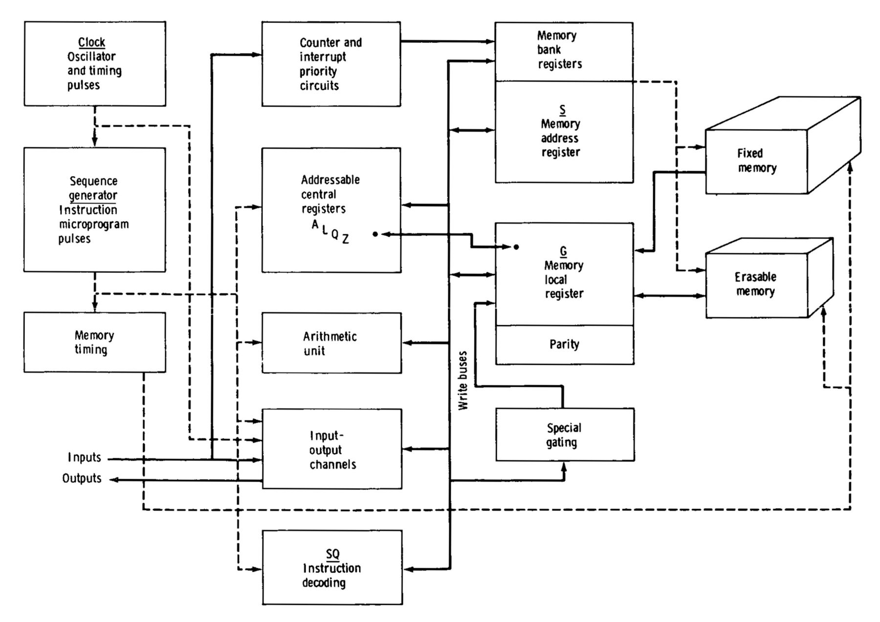 |
| AGC Block Diagram |
In the early 1960s, computer logic was expensive and voluminous, which led Apollo computer designers to define a simple instruction set with simple addressing modes and few registers. To circumvent these constraints, designers gave select memory locations magical properties that allowed them to behave as registers, up-counters, down-counters, and input/output interfaces. Involuntary instructions, such as PINC (positive increment), which incremented one of 29 dedicated erasable memory registers, and MINC (minus increment), which decremented the same memory registers, were used to acquire and store IMU pulse-integrating pendulous accelerometer data. Designers also created interpretive instructions, which instituted a uniform means to create subroutine environments, call the subroutines, and pass data to and from them. Designers also created an executive with scheduling, a wait list, and cooperative/preemptive multi-programming.
Block I
Block I was the first Apollo computer design that could actually function in a spacecraft. It was based on the AGC4B, but was still smaller. Its gates were interconnected via welded leads; up to 120 gates were packaged in modules with 140-pin connectors. Thirty-six of these logic modules comprised the Block I computer logic functions. Discrete components were still used for the oscillator, power supplies, interface, and memory electronics. Testing on the Raytheon-produced AGC4B began in January 1964. Raytheon also built AGC5, another test computer for use at the MIT/IL, along with 5 core-rope simulators, 27 computer simulators and 9 calibration consoles. Raytheon completed and delivered AGC6, the first Block I computer, in August 1964.
 |
 |
 |
| Early Block I AGC at the USSRC |
Coincident-Core Memory Sense Amplifier |
|
Early computers were sensitive to electromagnetic interference (EMI). Cables connected to the computer acted as antennas and picked up radiated electrical energy, inducing transient computer errors. Power cycling of attached guidance-system equipment was also problematical. NASA imposed an EMI specification on 17 Oct 1963. However, adherence to the NASA EMI spec increased rather than decreased computer and interfaced-equipment errors. Bucking established procedure, engineers connected the computer's signal ground to the I/O cable shields. They also installed switches that opened paths to long wire runs used by ground support equipment. These measures eliminated susceptibility to power transients and electrostatic discharges.
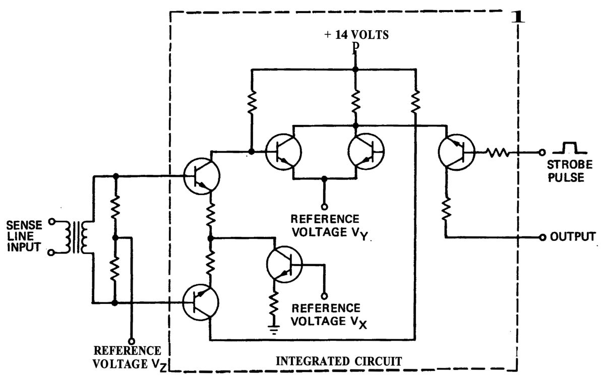
Before the Block I computer reached production, a custom differential memory sense amplifier integrated circuit was developed. This device contained the equivalent of six NPN bipolar transistors and eight resistors. This was advantageous due to the small integrated circuit size and close component characteristic match versus the previous sense amplifiers made with discrete components.
Block II
During early 1963, everyone wanted something new. Grumman, which was literally squeezing every ounce of weight from the LM, wanted weight reduction for the LM computer, along with a richer control mode variety. MIT/IL software engineers wanted more fixed memory. MIT guidance system designers wanted more computer speed, memory capacity, I/O capacity and suggested the Apollo computer hardware be tailored to the more expansive LM requirements. NASA wanted a digital autopilot, which further complicated the Apollo computer's interfaces. In May 1963, the MIT/IL suggested a guidance system redesign that allowed the CSM and LM computers to be very similar. While the two spacecraft computers were meant to be identical, the I/O interfaces were anything but. NASA Apollo program manager Dr. Joseph Shea insisted on a common CSM/LM computer with common I/O circuit specifications for both. NASA, North American Aviation, Grumman, MIT/IL and a bevy of other vendors each had its own idea of how the I/O interfaces should be defined. After considerable blood letting, an equitable distribution of dissatisfaction was achieved and a common interface defined.
 |
| First and Second Generation Integrated Circuits |
In February 1964, a new IC logic family featuring dual 3-input NOR gates in a single, smaller, 10-lead flatpack enabled a Block II computer design that was denser, faster, lighter, consumed less power, had more instructions, more fixed and erasable memory, more timers and more I/O channels. NASA proposed a primary AGC-based spacecraft control system with an independent backup capable of safe return to earth if the primary system failed. While painful, these implementation meetings simplified the computer designer and MIT/IL programmers' life.
These 1964 meetings led to broadly expanded AGC functionality, including the digital autopilot, increased mode control, radar interfaces, hand controller interfaces, sealed packaging, and numerous human-factors improvements. All of this led to the Block II AGC and DSKY hardware, a guidance system backup and redundancy philosophy, with independent guidance and control operating modes if the primary guidance system failed. If the command module AGC failed, ground control could assist with a safe return to earth; if the lunar module AGC failed, a separate guidance system (the Abort Guidance System) provide abort capability.
Design studies aimed at weight-saving resulted in a change from aluminum to magnesium alloys for the Block II computer frame, saving 12 lb. The magnesium required a corrosion-resistant finish that net the spacecraft contamination and corrosion-resistance requirements. The Block II design also met new requirements for electromagnetic interference resistance and fire proofing.
The Block II AGCs became known as the command module computer (CMC) and lunar module guidance computer (LGC). Both fixed and erasable memory sizes were increased to 36,864 and 2,048 words. This was necessary to accommodate new Block II features. The rope memory modules were redesigned so they could be changed without removing the computer from the spacecraft. The instruction count was expanded from 11 to 34 to improve branching, data handling, double-precision computations, I/O processing, etc. Computational logic was also enhanced to improve arithmetic logic unit carry propagation, multiply faster and divide faster. The memory cycle count for some instructions was reduced. The gate number rose but the package count dropped. The new Block II low-power 3 input NOR gates dissipated less than half the power of the Block I gates. Two gates were fabricated on a single silicon chip, doubling packaging density with a 10-lead flatpack. The Block II computer and DSKY also met new mechanical requirements, such as environmental seals on connectors or modules that could be damaged by the high-moisture spacecraft environment. Mechanical packaging schemes were derived from experience with the welded cordwood and other construction techniques that Polaris had used. NASA elected to use the Apollo computer as the basis of all spacecraft timing, counted down from the computer's 2.048 MHz oscillator.
| Computer Characteristic | Block I | Block II | Units |
|---|---|---|---|
| Fixed Memory | 24,576 | 36,864 | Words |
| Erasable Memory | 1,024 | 2,048 | Words |
| Word Size | 15 + 1 | 15 + 1 | Bits + Parity |
| Memory Cycle Time | 11.7 | 11.7 | μs |
| Normal Instructions | 11 | 34 | |
| Involuntary Instructions (interrupt, increment, etc.) | 8 | 10 | |
| Interrupt Options | 5 | 11 | |
| Input Counters | 20 | 29 | |
| Output to DSKY | 15 | 15 | Bits |
| Input from DSKY | 5 | 5 | Bits |
| Digital Telemetry Up/Down | Yes | Yes | |
| Interface Circuits | 143 | 227 | |
| Integrated Circuits | 4,100 | 5,600 | Gates |
| Integrated Circuits | 4,100 | 2,800 | Packages |
| Add Time | 23.4 | 23.4 | μs |
| Multiply Time | 117.0 | 46.8 | μs |
| Divide Time | 210.6* | 81.9 | μs |
| Double Precision Add Time | 1,650.0* | 35.1 | μs |
| Counter Incrementing | 11.7 | 11.7 | μs |
| Volume | 1.21 | 0.97 | ft3 |
| Weight | 87 | 70 | lb |
| Power Consumption | 100 | 70 | W |
| *Software subroutine | |||
4.0 Input/Output
 |
 |
| CMC Input/Output | LGC Input/Output |
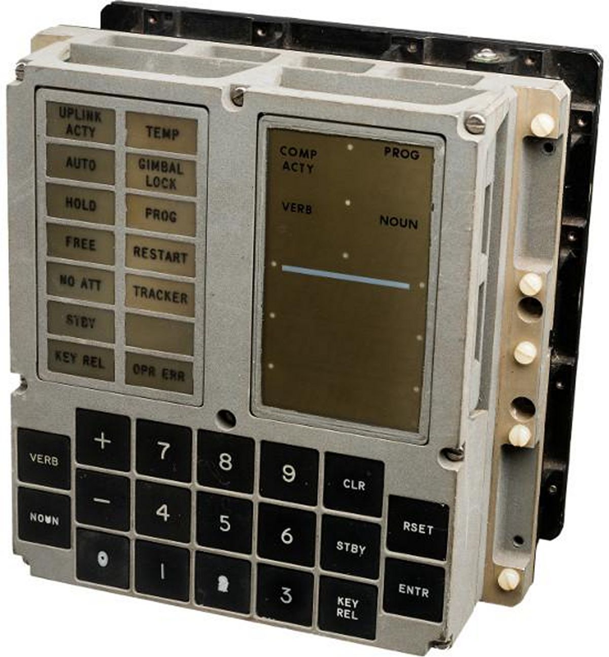
5.0 Human Interface
 |
 |
| DSKY | |
The display/keyboard, in conjunction with the hand controllers discussed in the CM and LM GNC sections, formed the AGC crew interface. The DSKY comprised three 5-digit-plus-sign 7-segment data displays (creatively named Register 1, Register 2 and Register 3), three 2-digit 7 segment displays (Program, Noun and Verb codes), a custom keyboard and several status indicators. The astronauts communicated with the computer using a verb-noun syntax using numeric verb (load, display, monitor) and noun (time, angle, identifier) codes. The Apollo computer interpreted these and acted accordingly.
6.0 Flight Software
Margaret Heafield Hamilton (17 Aug 1936 - ) led the team that developed CMC and LGS software. This monumental, continually-evolving and expanding task broke new ground on many fronts. NASA and the MIT/IL grossly underestimated the software development effort. The MIT/IL expended about 1,400 person-years prior to the first moon landing. Peak activity occurred in 1968 when 350 persons worked the project. Task assignments those working the project included designing the software, planning coding and testing activities, writing the code, testing the code, and certifying that the code met requirements. Considerable human and machine resources were allocated to testing. The programs had to be as nearly error-free as possible and any anomalies had to be understood and recorded for possible mission impacts.
The CMC software supported crewed or uncrewed (during testing) flight in earth orbit, translunar flight, lunar orbit, transearth flight and earth atmosphere entry. The CGC software supported crewed or uncrewed (during testing) flight in earth orbit, lunar orbit, lunar descent, and lunar ascent. Program behavior was determined by its hard-wired computer program, which could handle multiple simultaneous computational problems in real time on a priority basis. It also had a large number of signal interfaces for communication with other spacecraft systems.
| Command Module Computer (CMC) Programs | Lunar Module Guidance Computer (LGC) Programs |
|---|---|
| P00, Prelaunch CMC Idling | P00, Prelaunch LGC Idling |
| P01, Prelaunch Initialization | P06, Prelaunch LGC Power Down |
| P02, Prelaunch Gyro Compassing | P12, Ascent Nominal Program |
| P03, Prelaunch Optical Gyro CompassingVerification | P70, Descent Propulsion System Abort |
| P06, Prelaunch CMC Power Down | P71, Ascent Propulsion System Abort |
| P11, Boost Earth-Orbit-Insertion Monitor | P20, Coasting Flight Rendezvous Navigation |
| P15, Boost TLI Initiate/Cutoff | P21, Coasting Flight Ground-Track Determination |
| P20, Coasting Flight Universal Tracking and Rendezvous Navigation | P22, Coasting Flight Lunar-Surface Navigation |
| P21, Coasting Flight Ground-Track Determination | P25, Coasting Flight Preferred Tracking Attitude |
| P22, Coasting Flight Orbital Navigation | P27, Coasting Flight LGC Update |
| P23, Coasting Flight Cislunar Navigation | P30, Targeting External Ov |
| P27, Coasting Flight CMC Update | P32, Targeting Coelliptic Sequence Initiation (CST) |
| P24, Coasting Flight Rate-Aided Optics Tracking | P33, Targeting Constant Delta Altitude (CDH) |
| P29, Coasting Flight Time of Longitude | P34, Targeting Transfer-Phase Initiation (TPI) |
| P79, Coasting Flight Final Rendezvous | P35, Targeting Transfer-Phase Midcourse (TPM) |
| P30, Targeting External Ov | P72, Targeting CSM Coelliptic Sequence Initiation |
| P32, Targeting Coelliptic Sequence Initiation (CSI) | P73, Targeting CSM Constant Delta Altitude |
| P33, Targeting Constant Delta Altitude (CDH) | P74, Targeting CSM Transfer Phase Initiation |
| P34, Targeting Transfer-Phase Initiation (TPI) | P75, Targeting CSM Transfer Phase Midcourse |
| P35, Targeting Transfer-Phase Midcourse (TPM) | P76, Targeting CM Target Ov |
| P37, Targeting Return-to-Earth | P77, Targeting Impulsive Ov |
| P72, Targeting LM Coelliptic Sequence Initiation | P40, Powered-Flight Descent Propulsion System Maneuver |
| P73, Targeting LM Constant Delta Altitude | P41, Powered-Flight Reaction Control System Maneuver |
| P74, Targeting LM Transfer Phase Initiation | P42, Powered-Flight Ascent Propulsion System Maneuver |
| P75, Targeting LM Transfer Phase Midcourse | P47, Powered-Flight Thrust Monitor |
| P76, Targeting LM Target Ov | P51, Alignment IMU Orientation Determination |
| P31, Targeting Height Adjustment Maneuver | P52, Alignment IMU Realign |
| P36, Targeting Plane Change Maneuver | P57, Alignment Lunar Surface Align |
| P77, Targeting Impulsive Ov | |
| P40, CSM Powered-Flight Service Propulsion System (SPS) Maneuver | |
| P41, CSM Powered-Flight Reaction Control System (RCS) Maneuver | |
| P47, CSM Powered-Flight Thrust Monitor | |
| P51, Alignment IMU Orientation Determination | |
| P52, Alignment IMU Realign | |
| P53, Alignment Backup IMU Orientation Determination | |
| P54, Alignment Backup IMU Realign | |
| P61, Entry Preparation | |
| P62, Entry CM-SM Separation and Pre-Entry Maneuver | |
| P63, Entry Initialization | |
| P64, Entry Post 0.05G | |
| P65, Entry Upcontrol | |
| P66, Entry Ballistic | |
| P67, Entry Final Phase |
Flight experience showed the value of error detection and alarms built into the hardware and software, and the system protection offered by these features. Margaret Hamilton fought NASA and her own management to include software error-detection features after her young daughter, while playing in the simulator, had entered a DSKY keystroke sequence that crashed the computer. NASA and MIT/IL management thought that the well-trained astronauts would never make a similar mistake, but when they did, Hamilton got her way and included error checking to the extent possible. The DSKY computer program was able to detect illogical inputs due to mispunched keys and signal operator error so that the astronaut could try again. Other error detection schemes were designed that caused the computer to "restart" automatically. Restart caused the program to go back a few steps to a point where the last known-good computation state was stored and then start fresh from that point. This was done so quickly that astronauts were only aware that it happened when the RESTART indicator light came on. More serious internal logical problems or procedural errors occasionally raised alarms requiring the astronaut manually to recycle back to the program start. The computer and its associated operating procedures were generally quite error tolerant. The use of a digital computer to tie together the system measurement, processing, and command functions provided enormous design flexibility, saving considerable time, effort, and expense.
Digital Autopilots
Apollo spacecraft attitude control presented a significant design challenge. These autopilots had had to consider many permutations of several variables.
Third were the flight regimen variations from free-fall coasting flight, rocket powered accelerated flight, and aerodynamic-influenced atmospheric entry.
Fourth were the wide variations in spacecraft dynamic properties as fuel was expended, causing mass and inertia variations, changes in bending frequencies and their damping, and fuel slosh modes and coupling.
Apollo autopilot designs were originally conventional analog systems. But in 1964, NASA chose to incorporate these autopilots into the CM and LM digital computers. However, a direct digital equivalent to the analog autopilot design candidates would not work. Sampling rates would have been higher than the digital computer could accommodate. Instead, design approaches adaptable to digital processing were chosen and these exploited the flexibility and nonlinear computation capability available in a digital computer.
About 10% of the CM and LM computer memory was devoted to autopilots. During high activity, only 20 – 30% of computation time was used by the autopilot function.
Rate Derivation for Control
Control systems required some form of stabilization signal. Analog autopilots typically obtained this from angular-rate-indicating gyroscopes mounted to the vehicle structure. The Apollo primary guidance and control system lacked sensors that measured angular rate directly. Instead, attitude rate was derived by processing available attitude signals. The simple ratio of IMU-indicated attitude difference divided by time difference was sufficient and worked adequately for roll control about the thrust axis during powered flight. This scheme was inadequate for wider-bandwidth control problems. The attitude signals came from the IMU in quantum steps of about 0.01°; at such low rates no new rate indication information was available until the next angle increment change occurred. The system worked around this problem by using a computer model of the spacecraft's response to applied torques. This model includes the torque level obtained from firing reaction control jets, the torque obtained from the thrust acting on the engine at the existing engine gimbal angle, and the presently-existing spacecraft moments of inertia. As attitude jets were fired and engine gimbal angles changed, this model could derived new angular rate estimations. Periodically, this rate estimation's integral was compared with the IMU angles and the weighted difference applied to the model state, bringing it back to consistency with the spacecraft's actual orientation history. This rate estimation scheme worked very well, producing a fast-responding low-noise spacecraft rate indication without special gyroscopes and their associated weight, power, and reliability penalties.
Autopilot Gain Scheduling
The digital computer's computation capabilities were used to make a very effective autopilot gain scheduling scheme. Acceleration measured by the IMU during powered flight in conjunction with known engine specific impulse allowed the computer to estimate spacecraft mass loss as propellant was expended. Predetermined polynomials were then evaluated to estimate spacecraft moments of inertia, which directly allowed angular acceleration estimates produced by the controlling torques. Thus, wide spacecraft dynamic characteristic variations were accommodated with near optimum response.
Other Control Systems
The Free-Fall Flight Control Systems for the CM, CSM, and LM operated using appropriate efficient phase plane logic. Each autopilot iteration cycle examined the existing angle error and angle rate error. If either of these were outside chosen deadbands, the computer scheduled and executed open loop two reaction jet firings that would bring both angle and rate errors to zero simultaneously. Inside the chosen deadband, the control oscillated slowly in a minimum reaction jet impulse limit cycle determined by the 14-millisecond minimum firing permitted by the jet design. These systems were very efficient in reaction jet fuel expenditure and minimize the number of jet on-off cycles.
An example of the flexibility with which the digital computer could augment control system design was a last-minute change added to the Apollo 9 flight procedures. The crew wanted the control system in free-fall orbital flight to hold attitude with respect to the local vertical without their attention. This feature had been proposed earlier as a program in fixed memory but had not been incorporated. A week before the scheduled launch, a simple procedure to load a program and data into erasable memory by means of a few dozen DSKY keystrokes was transmitted to the astronauts. This provided the crew with the desired feature, which operated in orbit as advertised.
The LM Ascent Powered Flight autopilot obtained control torque only by using the RCS jets, since the ascent engine was fixed. This control, then, operated very similarly to the free-fall coasting flight autopilots previously described, but with additional torque estimates arising from main engine thrust offset from the spacecraft center of gravity. Controlled limit cycles then normally operated so that, unless error margins were exceeded, reaction jets were fired only to oppose the ascent engine thrust misalignment torque.
The CSM Powered Flight autopilot used a fast-acting main engine swivel to obtain pitch and yaw control torques. The computer compared estimated spacecraft rates with the desired rates being commanded by the guidance programs. The resulting rate errors were integrated and shaped by a seventh order difference equation filter, the outputs of which command the engine swivel servos. At the time the design was committed, there was little confidence in the dynamic bending mode and fuel slosh models available, especially for the CSM docked to the LM. Bending modes lower than one Hz were thought possible. Accordingly, the gains and filter characteristics were chosen conservatively so that a wide tolerance margin to spacecraft dynamic variations was obtained but at a cost of slow response and low static gain. A special loop to calculate thrust misalignment was provided so that the steady state autopilot error resulting from this low loop gain would not be excessive. However, initial thrust misalignment caused a large initial attitude error transient peaking at about 10 seconds after engine ignition at an amplitude dependant upon initial thrust misalignment. Short burns of around 10 seconds while docked to the LM left fairly high residual out-of-plane error velocities. However, these errors were within Apollo tolerances. Better models for the docked spacecraft dynamics become available and bending frequencies were assured to be greater than 2 Hz. A much higher gain design later capitalized on this better information, reducing residual velocity errors to about 10% of the earlier design.
The LM Descent Powered Flight autopilot was originally intended to use a slow responding engine swivel to put the thrust vector through the center of gravity with a slow computation loop. Dynamic control torques in all axes would have been provided by reaction control jet firings. Although the engine trim gimbal could be commanded at the fixed rate of only 0.2°/sec on each axis in response to discrete signals from the computer, the challenge to make this provide most, if not all, the dynamic control was motivated by the reaction control jet fuel savings and the significantly fewer firings that would result. Response to this challenge was ambitious because of the very slow speed with which the engine swivel could affect changes in torque even thought five times as much torque could be obtained at maximum angle as was obtained from firing a jet pair. A jet torque minimum impulse was obtained within 15 milliseconds of the command while the same impulse required 400 milliseconds with the engine gimbal. Nonlinear control laws were examined an a formulation for a third order minimum time control was achieved. This autopilot used computer- generated attitude, attitude rate, and attitude acceleration estimates made every 0.1 second upon which to base a policy for commanding the appropriate trim gimbal axis. This time sequence resulted in the spacecraft angular acceleration, angular velocity, and angle error all zeroed simultaneously in the fastest possible time. Provision was made to fire the reaction jets appropriately if the angle error got past a threshold, but in simulations this logic was rarely exercised.
The benefits of this nonlinear control law became particularly evident when it appeared that the total time the downward firing jets could operate in the descent configuration was severely limited because the RCS jet plumes would burn the descent stage More thermal insulation would have been a serious weight penalty, which was avoided by the development of this autopilot design requiring almost no jet activity. But the real test of this LM descent autopilot control system came in Apollo 9. Although the possibility for using the LM descent engine to push the docked CSM was considered as a backup for service propulsion failure, this configuration became essential to the Apollo 9 mission. It was the only safe way of achieving the long descent engine burn that qualified the engine for lunar landing. But with the LM pushing the CSM another problem appeared. The LM forward firing jets were then severely limited due to their impingement on the docked command module. The solution was to for the computer cease all X-axis jet activity forward or aft when so commanded by astronaut DSKY input and fly the LM when pushing the CSM entirely with the slow moving trim gimbal. This was how the descent engine burn for over six minutes and over 1,700 fps was controlled in the Apollo 9 flight. The residual cross axis velocity error at the end of the burn indicated only 0.1 fps. Attitude error during the burn remained small and no evident excitation of bending or slosh modes was seen.
Rendezvous Navigation
A particularly critical Apollo mission phase was the LM/CSM rendezvous following the LM ascent from the lunar surface. The rendezvous navigation problem was to measure the positions and velocities of the two spacecraft in a common reference frame and from this to determine the maneuvers unite the two spacecraft in a prescribed fashion. The maneuvers and flight paths followed in manned space flight rendezvous have been from the so-called "concentric flight plan", which was developed to make a backup plan possible with both by the astronauts using simple onboard chart solutions and by ground tracking calculations in case the primary system failed.
As the active partner in the lunar landing mission rendezvous, the LM made its navigation measurements with the IMU during maneuvers and with the rendezvous radar during coasting phases. The rendezvous radar, when successfully tracking the CSM, directly measured the range and range rate for the computations. The radar antenna gimbal angles with respect to the spacecraft were sent to the computer, along with the spacecraft orientation measured by the IMU from which the computer could determine the direction to the CSM in the stable coordinate frame to which the IMU was aligned. Since the radar antenna and the IMU were mounted at separate locations in the spacecraft, the processing provided for an unknown but assumed constant misalignment between the two and corrected the line-of-sight calculation for a computed estimate of this misalignment. The estimates of this misalignment and the position and velocity of one of the two vehicles were updated recursively in a Kalman optimum filter as radar measurements were incorporated periodically. The navigation states were used in several programs in the computer to produce the targeting parameters for the various rendezvous maneuvers that were executed with inertial guidance steering.
While the LM, as the active vehicle, was performing its rendezvous navigation, the sensors and computer in the CM were being used to provide an independent check on the LM rendezvous navigation. It also was prepared to take over the active roll in case the LM got into trouble and needed rescue. In these functions the CM navigator make LM line-of- sight direction measurements with the CM optical system. In addition, range data measured within the communication system was available to the computer.
A CSM Active Rendezvous was exercised in earth orbit during the Apollo 7 mission using the Saturn S-IVB stage as a target. The CMC's P20 rendezvous program satisfactorily pointed the optics to the S-IVB for optics acquisition; the navigator, Don Eisele, was able to do satisfactory target tracking and marking, and the computer came up with the critical TPI (transfer phase initiate) maneuver data to put the CSM on a trajectory intersecting the S-IVB. This onboard solution matched the ground tracking solution within a fraction of a foot per second. The onboard solution was used to target and guide the 18 ft/sec maneuver using the reaction control thrusters. Further optical tracking following this was performed for a midcourse correction, which was only about 2 ft/sec. No other midcourse corrections were needed. Braking was done visually by the crew.
On the ground, mission control was feeding tracking network data to the MSC real-time computer complex. Initial vehicle separation was followed by several maneuvers that brought the LM to the intended position and orbit from which the rendezvous would start. The LM was about 10 nautical miles above and about 70 nautical miles behind the CSM. The descent; stage was jettisoned and the reaction control jets used to make the initial rendezvous maneuver based upon the LM onboard solution. The initial rendezvous maneuver was intended to cause the LM to pass through a point behind and below the CSM where a constant delta height (CDH) burn would put the LM in a trajectory below, behind, and concentric with the CSM orbit. The onboard LM `solution for the CDH maneuver was executed with the LM ascent engine.
With the LM behind, below, and concentric with the CSM it was now catching up with the CSM. The computation capability for the final critical transfer phase initiate (TPI) maneuver to put the LM on an intercept trajectory with the CSM was included in the CM computer program so that this solution was also available. Another TPI maneuver parameter of special interest was the time, measured from earth liftoff, that the maneuver was to be initiated. The LM, CSM and ground sources agreed closely.
The. TPI maneuver was made by the LM with its own solution using the reaction control jets, During the 20 minute coast towards the CSM, the intercept trajectory was improved by two small midcourse corrections determined onboard. The line-of-sight rates as the LM approached the CSM indicated zero. The braking maneuver was done manually to the prescribed velocity step versus range schedule.
This rendezvous exercise in earth orbit was designed to duplicate as closely as possible the LM return to the CSM orbiting the moon after the lunar landing. The excellent comparisons of the independent navigation being performed on each vehicle and with ground tracking results provide a measure of the spacecraft development maturity in preparation for the lunar landing.
Midcourse Navigation
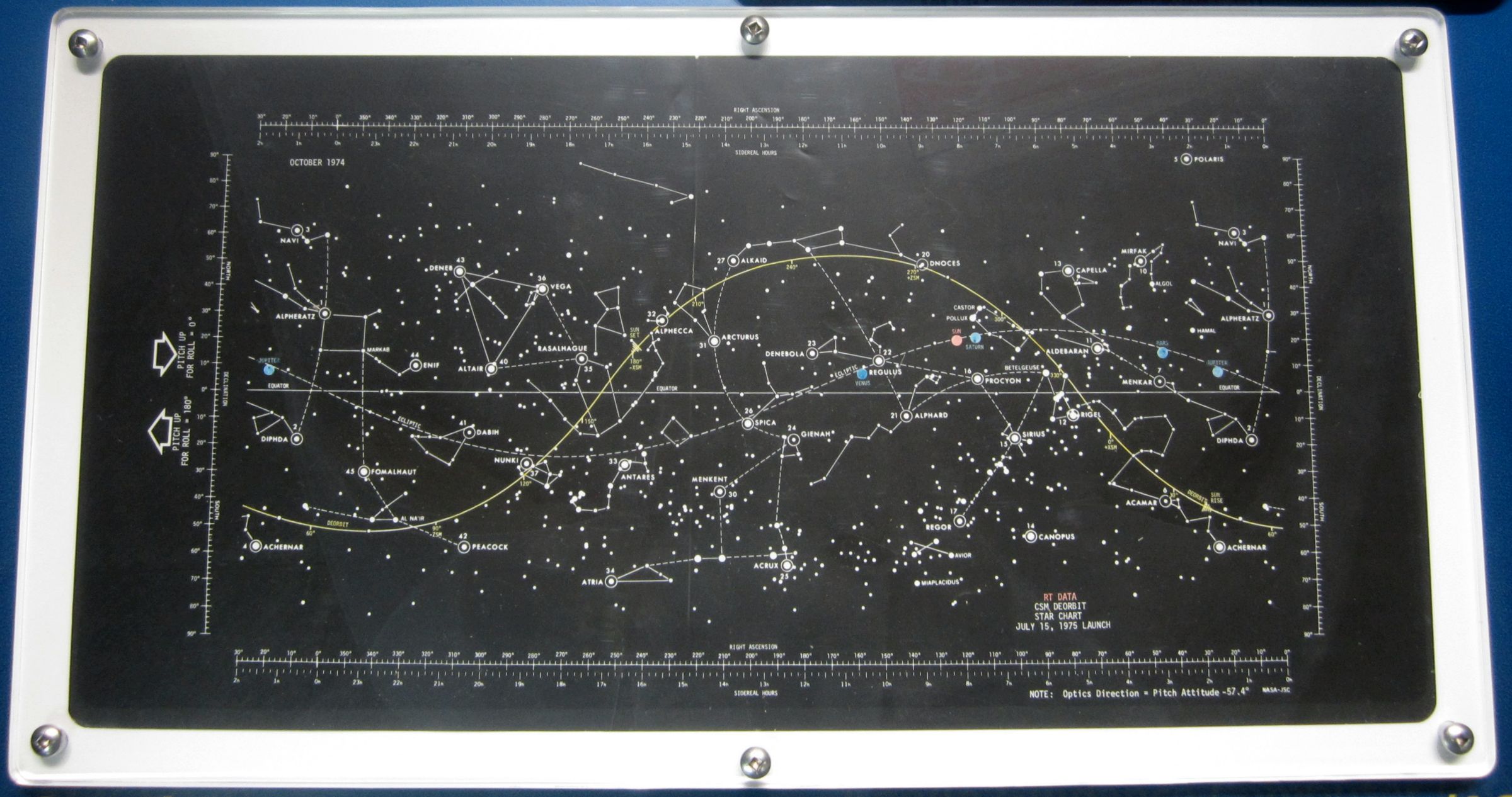 |
| AGC In-Memory Star Chart |
For onboard midcourse navigation between the earth and moon, the apparent positions of these bodies against the star background as seen from the spacecraft was measured by superimposing images of the two-line-of-sight sextant in the command module. The output of the sextant was the measured angle between a known reference star and an earth or moon visual feature. This angle was transmitted to the computer as a serially incremented count of 10 arc seconds per count. Therefore, before its use and periodically during its use, the navigator had to zero the instrument by superimposing any celestial image from the two lines of sight on top of itself. This calibration process zeroed the navigation angle counter in the computer and corrected for any fixed angle error in the instrument that might have arisen from thermal changes.
To make a navigation sighting, the computer midcourse navigation program (P23) could point the sextant's two lines of sight at the reference star and landmark identified by the navigator. It was then the navigator's task to center the superimposed star image onto the landmark, if landmarks were being used, or onto the near or far substellar point of the horizon, if the horizon target was being used. When superposition was achieved, the navigator pushed the MARK button, which signaled the computer to record the navigation angle and the time of mark. Using a Kalman optimum recursive filter formulation, the computer then determined the state vector change this measurement would cause if incorporated and displayed the resultant position and velocity changes. If the navigator was satisfied with the display and with his mark, he allowed the computer to incorporate the state vector change.
The first manned trip to the moon's vicinity during the Apollo 8 Christmas 1968 mission gave an excellent test of the Apollo system's onboard navigation capability. Although ground tracking navigation was the primary system, the onboard navigation system confirmed a safe trajectory and provided a backup for earth return if ground assistance became unavailable.
Apollo 8 used sun-illuminated visual Earth Horizon Navigation References rather than landmarks for operational simplicity. It was expected and confirmed from earth by astronaut Don Eisele in Apollo 7 that the earth's horizon does not provide distinct visual targets. Moreover, the filter in the sextant beam splitter, designed originally to enhance the contrast between water and land when looking down at the earth, filtered out the blue in such a way as to make the horizon even less distinct at the higher altitudes where weather phenomena were less likely to cause optical altitude uncertainty. Originally a blue sensitive photometer had been designed for horizon detection in prototype sextant models but was removed from the production systems since it had been decided that ground tracking would be the primary midcourse navigation source. Without the photometer, interest in the earth's horizon as a visual target resulted in demonstrations on simulators that, in some subjective way, the human with a little experience can choose an altitude sufficiently repeatable, at least as good as only several kilometers. Accordingly, a few weeks before the Apollo 8 launch the navigator, command module pilot Jim Lovell, spent a few hours on the sextant earth horizon simulator at MIT/IL for training and to calibrate the horizon altitude he seemed to prefer. He was remarkably consistent in choosing a location 32.8 kilometers above the sea level horizon. This value was recorded into the CMC.
The mission plan was to examine the sextant angle measurements made early while still near the earth and, based on the spacecraft state vector measured by ground tracking, infer in real time the horizon altitude Lovell was using. This was done because the MIT/IL simulation fidelity was suspect. After the first eleven earth sightings at distances from 30 to 35 thousand nautical miles from earth, it was estimated that he was using an 18.2 kilometer altitude and the CMC was reloaded with this new value.
The first Translunar Midcourse Navigation correction of almost 25 ft/sec was performed following the horizon calibration. This large correction was due to trajectory perturbations resulting from the maneuvers performed in getting the spacecraft safely away from the launch vehicle third stage. After this midcourse maneuver, the CMC state vector was made to agree with the value obtained from ground tracking. The important parameter of the translunar navigation, predicted perilune altitude, was 69.7 nautical miles – very close to a true value estimate later of 68.8. The astronauts continued to refine the CMC state vector with additional navigation sightings.
The transearth flight of Apollo 8 after 10 lunar orbits also provided a good measure of the onboard navigation capability. The transearth injection firing of the service propulsion system was targeted by ground data and executed in back of the moon by the onboard digital autopilot and guidance systems. This 3,522.5 ft/sec maneuver was followed by a single midcourse correction of 4.8 ft/sec 14.7 hours later resulting in entry conditions at 400,000 feet altitude above the earth 57 hours from the moon which were 0.8 ft/sec faster and 0.1 degree shallower than planned. Although the primary navigation during this period was again the ground tracking network, Lovell performed 138 navigation measurements as a monitor and backup. In order to see what would have happened without ground assistance, the actual onboard measurements were incorporated in a simulation with the computer initialized to the actual onboard state vector as it existed when the spacecraft emerged from behind the moon. The single transearth midcourse correction was added appropriately to this simulation in accordance with that actually measured by the inertial guidance system (In the actual flight a new ground-determined state vector was loaded into the computer at the time of this maneuver.) The last of the 138 measurements was completed 16 hours before entry. The incorporation of these measurements left a hypothetical onboard estimate of entry flight path angle at 400,000 feet of -6.38° as compared with the ground tracking estimate of -6.48°. Either value difference was well within the conservative safe tolerance of ±0.5° from the -6.5° entry corridor center value. Another parameter of concern at this entry interface was the error in altitude rate. The onboard estimate of this quantity differed from that estimated by ground tracking by 236 ft/sec. The conservative allowable tolerance was 200 ft/sec.
It should be emphasized had ground. data not been available, continued onboard measurements would have optimized the final midcourse correction and state vector for safe earth atmospheric entry. The onboard. navigation system's capability to safely return the spacecraft to earth was clearly demonstrated.
Earth Atmosphere Entry
The unmanned Apollo 3 flight was designed to give the CM heat shield a high entry heat load test. Accordingly, the onboard system was targeted to reach for maximum range far down near the toe of the entry footprint. Instead of the expected 0.3 lift-to-drag ratio, the command module had a value of only about 0.28, which was not enough to fly the whole planned distance. The spacecraft entered the atmosphere at 28,500 ft/sec but fell into the ocean 200 nautical miles short of the recovery forces after flying full lift up in a vain attempt to make the range good. Heat shield test objectives were met, however, and the inertial navigation indicated position was within a few miles of actual recovery coordinates, In all flights following this one, the lift to drag ratio was extremely close to the intended value.
The entry of unmanned flight Apollo 4 was perhaps the most spectacular from an engineering point of view of any entries yet. Intended to be a high heat rate test on the heat shield., the entry velocity was unexpectedly higher than planned. By error, the ability to send the service propulsion's burn intended cutoff signal, to drive the vehicle into the atmosphere at the test speed was taken away from automatic onboard control. The ground cutoff signal was sent 13.5 seconds late causing 200 ft/sec more velocity than intended. But this made a more stringent higher velocity test at 36,500 ft/sec, which was faster than a normal lunar mission return. The entry range was targeted long to 2,500 nautical miles, which meant the entry guidance after the velocity had been lowered sufficiently by drag in the upper atmosphere, steered the CM up again out of the atmosphere for a ballistic lob and reentry. Estimated error at the target at splash was less than 2 miles. This high energy entry in November 1967 was a full year before the first Russian high-speed return of their unmanned circumlunar flight of Zond IV.
The unmanned Apollo 6 entry was to have been similar to the previous Apollo 4 CSM flight. Unfortunately problems with the Saturn S-IVB stage that wouldn't restart resulted in the last instant change to have the CSM perform the simulated translunar injection burn using onboard guidance and the service propulsion engine. This unplanned CSM fuel use left the tanks without enough propellant to drive the CM into the atmosphere at lunar return speed. Thus the entry interface velocity was only 32,800 ft/sec. Theoretically, the entry range and landing target planned was within the smaller footprint of this lower velocity. However, a logical flaw in the entry computer program, known before flight but not expected to be important, caused the CM to waste lift early in the trajectory at less than full value so that when the initial phase was complete and full lift finally commanded, it was too late. The CM landed 50 nautical miles short. Nevertheless, the onboard inertial navigation indicated landing coordinates within 2 miles of the ground tracking data.
Apollo 7, the first manned flight, gave the entry system a good test in its orbit return at 25,850 ft/sec. The commander stayed with manual control longer than expected while he was watching to make certain that the automatic system was indicating logical entry steering commands. The CM pilot had observed that the computer power might not be functioning. After being satisfied the computer was working, he finally turned the entry over to the automatic system under the normal single "ring" configuration in which only half of the CM reaction control jets were active. Later, after an unexplained loud noise and suspected but late unconfirmed thruster malfunction, they switched to two ring operation. These variations from the planned operation were handled smoothly by the entry control system.
The return of Apollo 8 first men from the moon and the return from the Apollo 9 earth orbit in were uneventful except for the excitement of the landing in view of the recovery carriers.
Entry Accuracy
Much public interest was given to the accuracy with which the spacecraft landed at the ocean target point. From an operational point of view, NASA and the Navy recovery forces were concerned with accuracy sufficient to effect a safe and quick recovery. This was certainly demonstrated. The actual landing point with relation to the carrier at splashdown and at a later pickup time were dominated by the spacecraft motions, winds and waves while on the chutes and on the water, and by the recovery ship motions that maintained velocity for steering control. For engineering and design verification purposes the entry trajectory was examined carefully using available data. Analysis of the four completely successful automatic entries that were controlled to the target has revealed that the landing overshot the target, and the spacecraft motions after steering control was terminated were a strong contributor to a miss. The present guided control system stops active steering when the velocity drops below 1,000 fps. The steering logic expects one nautical mile more range to be added after control ceases to account for the distance to splash. No account was made for wind. It appears that if this model was increased in the computer to three nautical miles a significant error source would be removed. But again, no significant change in the operational ease of recovery would result. The errors were now small enough.
7.0 Conclusion
The attention lavished on the CMC and LGC hardware and their respective flight programs resulted in CSM and LM guidance, navigation and control systems with great resilience and flexibility.
When the Apollo 11 LGS was overwhelmed with excess superfluous rendezvous radar data during the first lunar landing attempt, the LGS did precisely what it was programmed to do — ignored the unimportant data excess and concentrated on the important high-priority spacecraft control task. An astronaut had misconfigured a selector switch, which allowed the rendezvous radar to feed what was essentially noise to the LGC. The LGC complained about running short of resources by issuing a few 1201 and 1202 alarms. Neither the astronauts nor the Houston flight controllers recognized these codes, but Steve Bales, a 26-year-old Houston guidance officer, and his colleague Jack Garman, had made a cheat sheet with all the program alarms enumerated. Bales consulted the sheet, saw that the alarms were of no immediate consequence, reported this to the FLIGHT DIRECTOR and the landing process successfully completed.
Apollo 12 launched on 14 Nov 1969 into a rain-free overcast sky. Although there was no reported lightning near the launch site, no one considered that the ionized first-stage exhaust plume might form a path from the cloud layer to ground. At T+36.5 seconds and then again at T+52, lightning struck the rocket. The launch vehicle instrument unit, which was guiding the rocket at that time, was unaffected. But the spacecraft's three fuel cells that were providing electrical power, the computer, and the IMU all dropped off-line. Meanwhile, ground controllers were seeing what amounted to gibberish on their consoles. EECOM John Aaron had seen similar gibberish before and had a solution. He told FLIGHT DIRECTOR, "Try SCE to AUX." This reset the signal conditioning equipment, which restored sanity to the ground displays. Once the astronauts restarted the guidance system and aligned the IMU, everything returned to normal. This tale is another testament to the AGC's resilience.
After Apollo 14 LM Antares undocked from the CSM Kitty Hawk, ground controllers noticed an indication the LM ABORT button had been pressed. When the astronauts were questioned, they denied pressing the button. One of them tapped on it and the ground indication went away. A stray solder blob inside the switch had floated into contact with switch contacts. If this erroneous switch closure could not be fixed, the lunar landing would have to be scrapped. Don Eyles, a 26-year-old MIT/IL mathematician who had programmed most of the LM landing software, dove into the problem and produced a work-around that caused the LGC to ignore the intermittent ABORT switch behavior. This is yet another example of the AGC's flexibility.
8.0 References
Apollo Guidance and Navigation System (Block I, Series 100) Student Study Guide (El Segundo, California: General Motors Corp., AC Electronics Division, 1 Jun 1965).
Apollo Spacecraft News Reference (Downey, California: North American Rockwell Space Division, 1967?).
Hall, Eldon C. Apollo Guidance, Navigation and Control: Volume III, Computer Subsystem (Cambridge, Massachusetts: MIT Charles Stark Draper Laboratory, 1972).
Hall, Eldon C. Journey to the Moon: the History of the Apollo Guidance Computer (Reston, Virginia: American Institute of Aeronautics and Astronautics, 1996).
Hoag, David C. The History of Apollo On-Board Guidance, Navigation and Control P-357 (Cambridge, Massachusetts: The Charles Stark Draper Laboratory, 1976).
Holley, M.D., W. L. Swingle, S.L. Buchmun, C.J. LeBlanc, H.T. Howurd, and H.M. Biggs Apollo Experience Report - Guidance and Control Systems: Primary Guidance and Control System Development NASA TN D-8227 (Washington, DC: National Aeronautics and Space Administration, May 1976).
Lunar Module LM 10 through LM 14 Vehicle Familiarization Manual LMA790-2 (Bethpage, New York: Grumman Aerospace Corporation, 1 Nov 1969).
Lunar Module News Reference (Bethpage, New York: Grumman Aircraft Engineering Corp., 1966).
Woods, David, et.al. Apollo Flight Journal (https://history.nasa.gov/afj/).
Send mail to
![]() with questions or comments about this web site.
with questions or comments about this web site.
![]()