

Bottom: SPS Engine Nozzle Exit Details
The SM Serice Propulsion System (SPS)
The service propulsion subsystem provided thrust for all X-axis velocity changes (ΔVs) throughout a mission and for SPS abort capability after the launch escape tower was jettisoned. The SPS consisted of a helium pressurization system, a propellant system, a propellant gauging and utilization system, and a rocket engine. The oxidizer was inhibited nitrogen tetroxide (N2O4), the fuel was Aerozine 50, a 50-50 blend of anhydrous hydrazine and unsymmetrical dimethyl hydrazine. The system incorporated displays and sensing devices that permitted the crew and earth-based stations to monitor its operation. Helium pressurized the SPS oxidizer and fuel storage tanks and the tank pressure forced propellants to sump tanks and finally to the SPS engine. Heat exchangers transferred heat from the propellants to the helium gas to reduce any pressure excursions resulting from a temperature differential between the helium gas and propellants. Relief valves maintained the propellant tank systems' structural integrity if an excessive pressure rise occured.
|
|
|
|
| Top: SPS Layout Bottom: SPS Engine Nozzle Exit Details |
SPS Functional FLow |
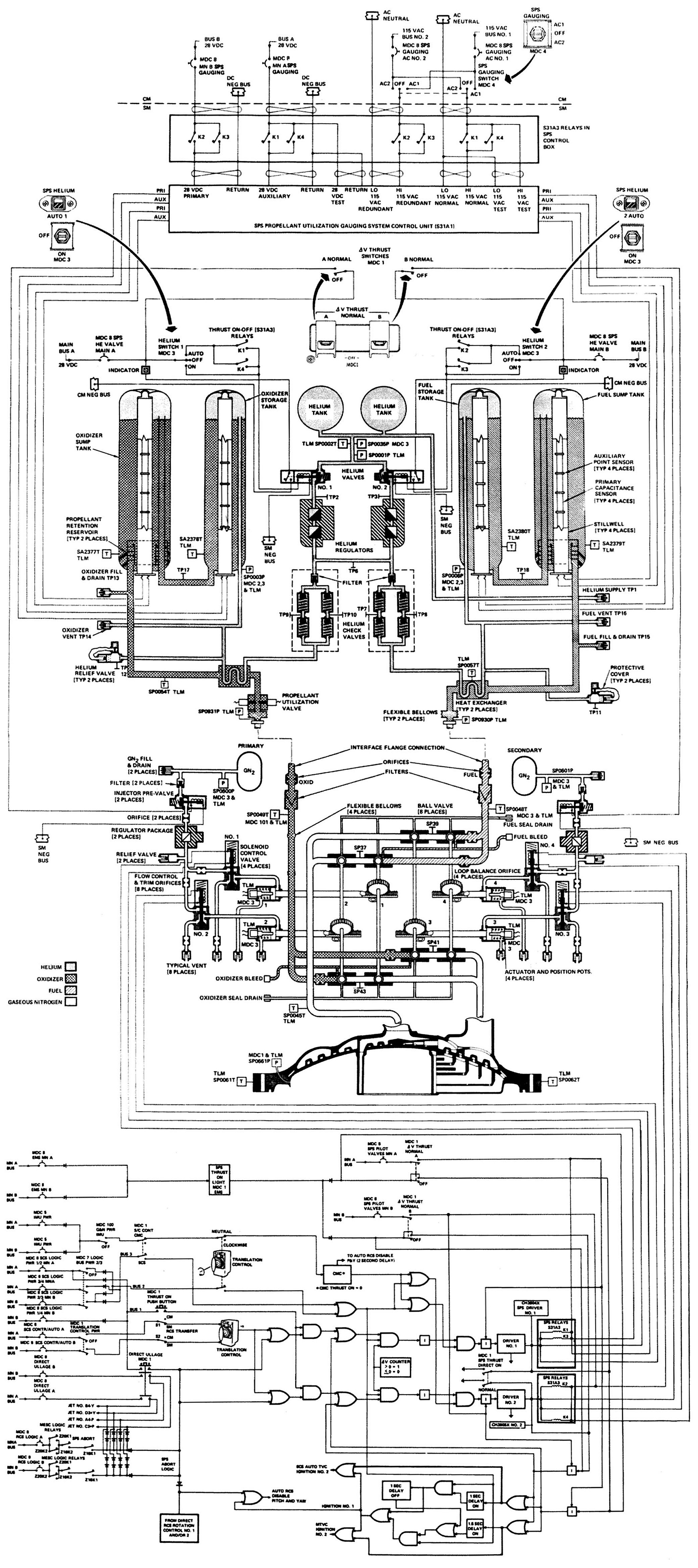
Helium Pressurization Subsystem
The pressurization subsystem consisted of two helium tanks, two helium pressurizing valves, two dual pressure regulator assemblies, two dual check valve assemblies, two pressure relief valves, and two heat exchangers. The critical components were redundant to enhance safety.
Two 40" diameter spherical helium tanks, manufactured by Sargent Industries of El Segundo, California, were located one atop the other in the SM center section upper half. Each was nominally filled to 3,600 ± 50 psia, had a 4,400 psia maximum operating pressure, 19.4 ft³ capacity, a 0.46" wall thickness, and weighed 393 lb.
The continuous-duty, solenoid-operated helium valves were energized open, spring closed and could be automatically or manually controlled. Each valve contained a position switch connected to the CM display console indicator above each valve switch.
A pressure-regulating assembly was located downstream of each helium pressurizing valve. Each assembly contained a primary and secondary regulator in series, with a pressure surge damper and filter on each regulating unit inlet. The primary regulator was normally the controlling regulator. The secondary regulator was normally open during a dynamic flow condition and did not become the controlling regulator unless the primary regulator allowed a higher than normal pressure at the secondary regulator. All regulator set points were in referenced to a bellows assembly that was vented to ambient. Only one the parallel regulator assembly regulated helium pressure under dynamic conditions. If downstream pressure caused the second assembly to lock up (close), the regulated pressure decreased below the non-operating assembly lockup pressure, allowing that assembly to again became operational. The primary regulator setpoint was 186 ± 4 psig while the secondary regulator setpoint was 191 ± 4 psig.
Each check valve assembly contained four independent check valves connected in a series-parallel configuration for added redundancy. The check valves prevented reverse propellant liquid and/or vapor flow, permitting helium pressure at the propellant tanks. Check valve inlet filters were in each check valve inlet.
The helium pressure relief valves consisted of a relief valve, a burst diaphragm, and a filter. If excessive pressure ruptured the burst diaphragm, the relief valve opened and vented the applicable system. The relief valve closed and resealed after the excessive pressure has returned to the operating level. The burst diaphragm provided a more positive helium seal than a relief valve alone. A filter prevented diaphragm fragments from fouling the relief valve seat. A pressure bleed device vented the cavity between the burst diaphragm and relief valve if there was leakage. The bleed device was normally open but closed when the pressure increased to a predetermined level. A protective cover over the relief valve vent port that prevented moisture accumulation arid foreign matter entrance was left in place at liftoff. The helium pressure relief valve diaphragm ruptured at 219 ± 6 psig. The valve; relieved at between 210 and 225 psig. The bleed device closed when increasing pressure reaches 150 psig in cavity, and reopened when decreasing pressure reached 20 psig.
An in-line counterflow heat exchanger consisted of the helium pressurization line coiled helically within an enlarged propellant supply line section. Helium flowing through the coiled line approached the propellant temperature prior to entry into the respective storage tanks, thus reducing pressure excursions to a minimum.
Propellant Subsystem.
The propellant subsystem consisted of two titanium fuel tanks (storage and sump) located in Sector 5, two titanium oxidizer tanks (storage and sump) located in Sector 2, and propellant feed lines. The four hemispherically-domed cylindrical propellant tanks were all manufactured by General Motors Corp's Allison Division of Indianapolis, Indiana.
The fuel storage tank had a 154.47" height, 45" inside diameter, 0.054" wall thickness, 128.53 ft³ volume and held 7,058.36 lb of Aerozine 50 at 110 psig.
The fuel sump tank had a 153.8" height, 51" inside diameter, 0.054" wall thickness, 161.48 ft³ volume, and held 8,708 lb of Aerozine 50 at 110 psig.
The oxidizer storage tank had a 154.47" height, 45" inside diameter, 0.054" wall thickness, 128.58 ft³ volume and held 11,284.69 lb of N2O4 at 110 psig.
The oxidizer sump tank had a 153.8" height, 51" inside diameter, 0.054" wall thickness, 161.48 ft³ volume and held 13,923.72 lb of N2O4 at 110 psig.
Total fuel capacity was 15,766.46 lb at 103.4%; gaugeable fuel was 15,252.7 lb at 99.9%. Total oxidizer capacity was 25,208.41 lb when the tanks were filled to 103.4%; gaugeable oxidizer was 24,389.1 lb at 99.99%. When empty, the tanks were pressurized to 10 ± 5 psig to prevent collapse.
Helium pressurizing the tanks forced propellant and/or helium gas from the storage tanks through their respective transfer lines to the sump tanks. A standpipe in the sump tanks allowed the propellant and/or helium gas from the storage tanks to pressurize the sump tanks. Propellants in the sump tanks were directed into retention reservoirs, to the outlet, and to the engine via flexible propellant feed lines. An umbrella retention reservoir, can, and screens were installed in the sump tank exit ends. The reservoir retained propellants at the sump tanks' exit end and the engine plumbing during zero-g condition, permitting engine ignition without an ullage maneuver when the SPS propellant quantity remaining was greater than 22,300 lb (56.4%) unless a LM DPS burn had occurred.
 |
 |
| Propellant Utilization Valve and Flag Display | Propellant Quantity Sensing |
Propellant Utilization and Gauging Subsystem (PUGS)
The PUGS consisted of a primary and auxiliary sensing system, a propellant utilization valve, a control unit, and a display unit. Primary and auxiliary quantity sensing, computing, and indicating systems measured propellant quantity. The primary quantity sensors were cylindrical capacitance probes, mounted axially in each tank. Oxidizer probes consisted of a pair of concentric electrodes with oxidizer used as the dielectric; fuel probes used a Pyrex glass tube, silver-coated with silver on its inside, as one capacitor conductor with fuel on the probe serving as the other conductor. The Pyrex glass formed a dielectric. The auxiliary system utilized point sensors mounted at intervals along the primary probes to provide a step function impedance change when the liquid level passes their location centerline. Primary propellant measurement was via the probes capacitance while auxiliary propellant measurement involved point sensors, seven in the storage tanks and eight in the sump tanks. Each point sensor consisted of concentric metal rings. The rings presented a variable impedance depending; on whether they were covered or uncovered by the propellants. When they propellants were between point sensors, the propellants remaining were integrated by a flow rate generator at a rate proportional to the nominal fuel and oxidizer flow rate. These sensor readings were processed and displayed to the crew as propellant remaining and unbalance readings, which suggested oxidizer flow rate changes for the crew to implement by adjusting the propellant utilization valve.
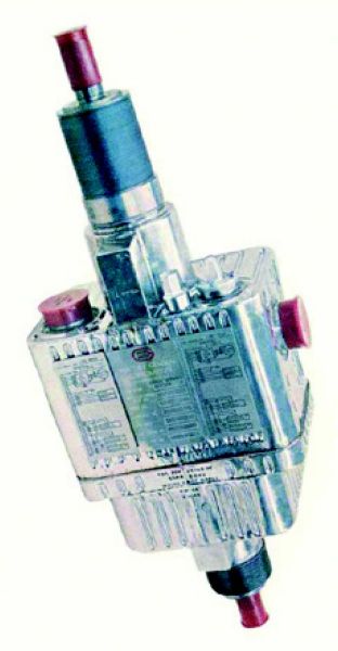
Aerojet AJ10-137 SPS Rocket Engine
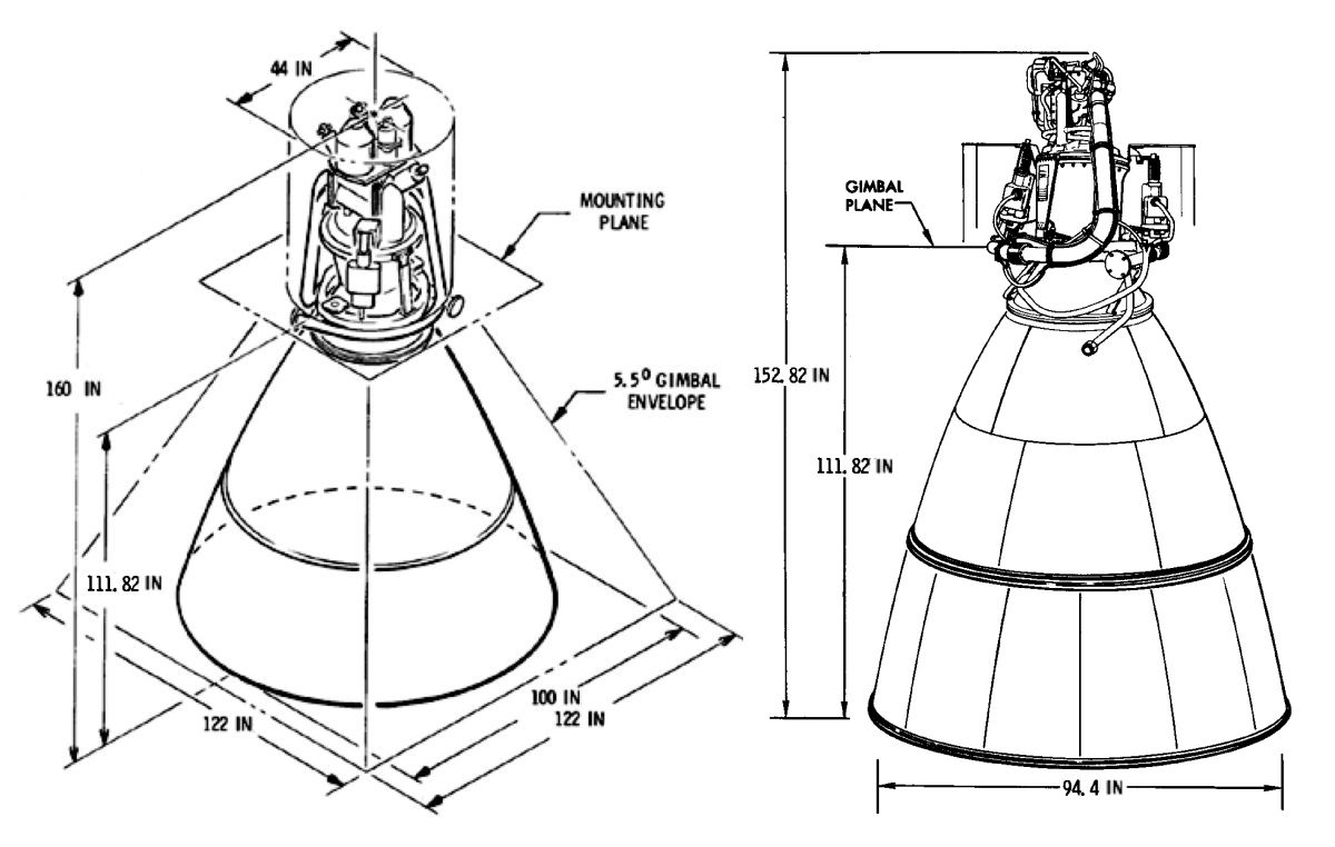
The SPS engine, built by the Aerojet General Corporation Space Propulsion Division of Sacramento, California, was located in the SM center section lower half, with its nozzle extension protruding more than 9 feet below the SM aft bulkhead. The SPS engine, including the nozzle extension, was 159.944" high; the nozzle extension exit diameter was 98.4" and the engine weighed about 650 lb. The thrust expansion ratio was 6:1 at the nozzle extension joint and 62.5:1 at the nozzle extension exit. It had a 750-second service life and could be restarted a minimum of 36 times.
The AJ10-137 consisted of a bipropellant valve assembly, an injector, combustion chamber, and nozzle extension. The bipropellant valve assembly admitted propellants to the injector with a high degree of reliability. The injector distributed the propellants through orifices in the injector face so the fuel and oxidizer impinged, atomized and ignited due to hypergolic reaction. The combustion chamber was ablatively and film cooled; the nozzle extension was radiation cooled. The engine was mounted to the SM structure and gimbaled to permit thrust vector alignment through the center of mass prior to thrust initiation and thrust vector control during a thrusting.
 |
 |
 |
 |
 |
 |
| Complete Engine | Thrust Chamber (heriocrelics.org) |
Injector | Combustion Chamber | Nozzle Extension Note Columbium Top and Titanium Bottom (heriocrelics.org) |
Operating Envelope and Engine Dimensions |
The bipropellant valve assembly consisted of two gaseous nitrogen (GN2) pressure vessels, two injector prevalves, two GN2 regulators, two GNP relief valves, four solenoid control valves, four actuators, and eight bipropellant ball valves.
Two GN2 pressure tanks, mounted on the bipropellant valve assembly and pressurized to 2,500 ± 50 psig at 68°F, supplied pressure to the injector prevalves for up to 43 actuations. These 120 in³ tanks were 9.6" high and 4.65" in diameter. One GN2 tank pressurized the primary pneumatic control system A and the remaining GN2 tank pressurized the secondary pneumatic control system B. Two solenoid-operated injector prevalves, one for each pneumatic control system, were energized open and spring closed. Controlled by CM switches, the injector prevalves, when open, allowed GN2 supply tank pressure through an orifice, into a regulator, a relief valve, and to a pair of solenoid control valves, which allowed propellant flow to the engine. A GN2 filter was installed between each GN2 pressure tank and injector prevalves. Another GN2 filter was also installed on each GN2 regulator outlet test port. A single-stage GN2 pressure regulator, installed in each pneumatic control system between the injector prevalves and solenoid control valves, reduced the GN2 pressure to 187 psig. A GN2 pressure relief valve, installed in each pneumatic control system downstream of the GN2 pressure regulators, limited pressure to the solenoid control valves to 350 ± 15 psig if a GN2 pressure regulator malfunctioned open. A GN2 orifice between the injector prevalve and regulator restricted GN2 flow and prevented damage to the solenoid control valves and/or actuators by relieving pressure overboard if the regulator malfunctioned open.
Four solenoid-operated three-way two-position GN2 control valves were used for propellant ball valve actuator control. Two solenoid control valves were located downstream of the GN2 regulators in each pneumatic control system. The solenoid control valves in the primary system were identified as 1 and 2 and the two in the secondary system were identified as 3 and 4. The solenoid control valves in the primary system controlled actuator and ball valves 1 and 2. The two solenoid control valves in the secondary system controlled actuator and ball valves 3 and 4. All were controlled by CM switches.
Four piston-type, pneumatically-operated GN2 ball-valve actuators controlled the eight propellant ball valves. Each actuator piston was mechanically connected to a pair of propellant ball valves, one fuel and one oxidizer. When the solenoid control valves were opened, pneumatic pressure was applied to the actuator opening sides. Spring pressure on the closing side was overcome and the actuator piston moved. Linear actuator connecting arm motion was converted to rotary motion using rack and pinion gear, which opened the propellant ball valves. When the engine firing signal was removed from the solenoid control valves, the solenoid control valves closed, removing the pneumatic pressure source from the actuator opening sides. The actuator closing side spring pressure then forced the actuator piston to move in the opposite direction, causing the propellant ball valves to close. The piston movement forced the remaining GN2, on the opening side of the actuator, back through the solenoid control valves where it was vented overboard. Each actuator incorporated a pair of linear position transducers, one of which supplied ball valve position information to CM indicators and one that supplied ball valve position information to telemetry.
 |
 |
 |
| Valve Assembly Exterior | Flow Diagram | Early (top) and Final (bottom) Propellant Ball Valve Designs |
Eight bipropellant ball valves distributed fuel and oxidizer to the engine injector assembly. Each pair of the four linked pairs consisted of one fuel and one oxidizer ball valve controlled by a single actuator. The four linked pairs were arranged in a series-parallel configuration so that the parallel redundancy ensured engine ignition and the series redundancy ensured thrust termination. When GN2 pressure was applied. to the actuators, each propellant ball valve rotated, aligning the ball to a position that allowed propellants to flow to the engine injector assembly. The mechanical arrangement was such that the oxidizer ball valves maintained an 8° lead over the fuel ball valves upon opening, resulting in smoother engine starts.
Bipropellant valve assembly check valves were installed in the four vent port solenoid control valve outlets, spring pressure vent port of the four actuators, and ambient vent port of the two GN2 pressure regulator assemblies. This protected the component seals from the hard vacuum of space.
Integral engine propellant lines routed each propellant from engine interface points in the gimbal plane area to the bipropellant valve assembly. The plumbing consisted of flexible bellows that permitted propellant line flexibility for engine gimbaling, orifices for adjustment of oxidizer/fuel ratio, and screens to prevent particles from entering the engine.
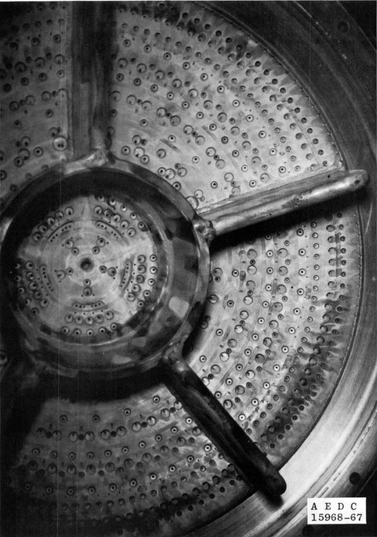
The injector assembly was bolted to the ablative thrust chamber attach pad. Propellant distribution through the injector was via concentric-annuli orifices machined in the injector assembly face and covered by concentric closeout rings. Alternate radial manifolds welded to the injector backside distributed propellant to the annuli. The injector was baffled to enhance combustion stability.
 |
 |
| Engine Feed Lines and Heaters | |
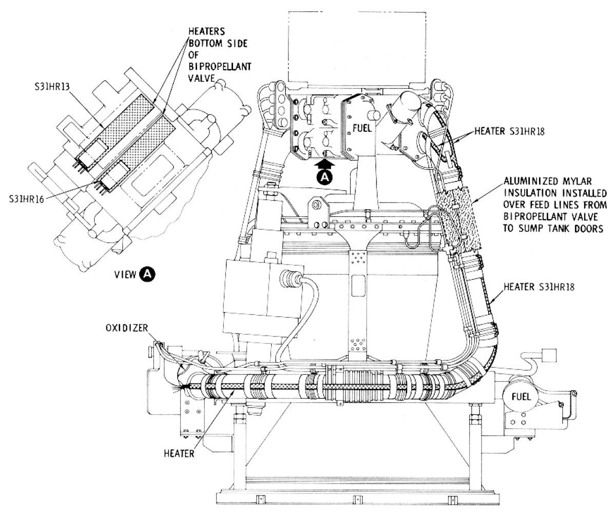
Ablative combustion chamber liner material extended from the injector attach pad to the nozzle extension attach pad. The ablative material consisted of a liner, an insulation layer and integral metal injector mounting attach flanges. A bell-contoured nozzle extension was bolted to the ablative thrust cumber exit. The nozzle extension was radiation-cooled and strengthened by an external stiffener. Six electric heaters were installed on tank feed lines from the respective sump tank outlets to the interface flange, on the engine feed lines from the interface flange to the bipropellant valve assembly and on the bottom side of the bipropellant valve assembly. Each heater contained redundant elements and provided heat to the tank feed lines, engine feed lines, bipropellant valve assembly and propellants. The heaters were manually controlled as a normal crew function.
The thrust mount assembly consisted of a gimbal ring, engine-to-vehicle mounting pads, and gimbal ring-to-combustion chamber assembly support struts. The thrust structure could providing ± 10° inclination about the Z-axis and ± 6° about the Y-axis. The thrust mount assembly oriented the SPS engine at null angles of +1° yaw and +2° pitch in order to compensate for spacecraft and thrust mount structure flex when the engine is firing.
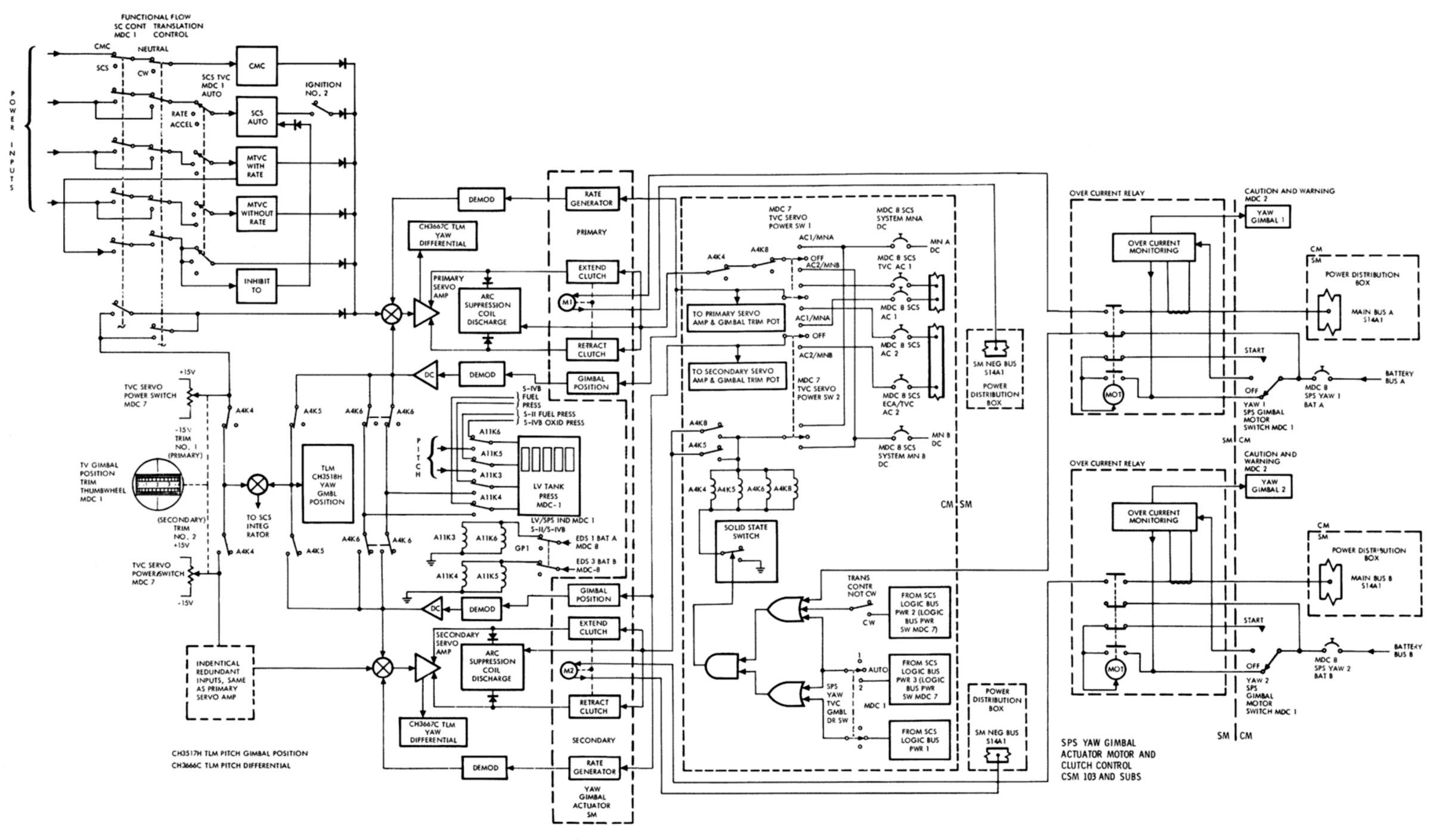
Dual sealed electromechanical servo actuators articulated the SPS engine for thrust vector control. Each actuator assembly consisted of four electromagnetic particle clutches, two DC motors, a bull gear, jack-screw and ram, ball nut, two linear position transducers, and two velocity generators. One motor and a pair of clutches (extend and retract) were identified as system No. l; the other motor and clutch pair were identified as system No. 2. An overcurrent monitor circuit was employed for each primary and secondary gimbal motor. Each gimbal motor and overcurrent monitor circuit was controlled by its own CM switch. The gimbal motor drive gear meshed with a clutch housing gear that also meshed with the opposite clutch housing gear, causing the clutch housings to counter rotate. Current applied to the rotating clutch housing electromagnet engaged that clutch for its particular function. A quiescent current was also applied to both extend and retract clutches to prevent engine movement during the mission boost phase. The gimbal motors were turned ON prior to jettisoning the launch escape tower in case an SPS abort was required, and then OFF again as soon as practicable to reduce gimbal motor and clutch housing heating. The dry powder magnetic particles, which were easily magnetized and demagnetized, increased friction between the rotating clutch housing and the flywheel, causing the flywheel to rotate. The flywheel was attached to the clutch output shaft and drove the bull gear, ball nut and finally actuator jackshaft to an extend or retract position, depending upon which clutch housing electromagnet received current. The greater the excitation current, the higher the clutch shaft rotation rate. Meshed with the ball nut pinion gear were two tachometer-type rate transducers. When the ball nut was rotated a rate transducer supplied feedback into the thrust vector control logic summing network to control jackscrew driving rates of the (acting as a dynamic brake to prevent over- or under-correcting). The jackscrew contained two position transducers that provided primary and redundant feedback to the summing networks and the CM visual indicators. The SM RCS auto pitch and yaw functions were disabled while the SPS engine was firing.
 |
 |
 |
| Actuator Exterior | Actuator Schematic | Yaw Axis Motor and Clutch Control |
AJ10-137 Engine Development Challenges
Clay Boyce participated in the 1960 Aerojet Apollo Service Propulsion System proposal and went on to became SPS engine engineering development manager. He later provided SPS engine technical support, worked on the Space Shuttle Orbital Maneuvering System engine, the Japanese N-2 Upper Stage, and the National Aerospace Plane. Boyce retired from Aerojet in 1991.
Aerojet submitted 29 proposals to 12 different primes and all but one selected what was to become the AJ10-137. The engine thrust and size was defined before the Lunar Orbit Rendezvous (LOR) Mode was selected. The earlier concept had the entire command/service module landing and lifting off from the moon. Aerojet got the Apollo SPS engine development contract in April 1962, the final decision in favor of LOR came later that year, and even though the engine was too large for the job, no one wanted to start over with a lower-thrust engine. The resulting 20,000 lbT pressure-fed engine had a low 100 psi chamber pressure and a 314-sec specific impulse, resulting in a large engine for its thrust. The original AJ10-137 concept featured a nozzle extension gimbaled at the throat, but this was later changed to head-gimbaled design that reduced the overall spacecraft length by about 3.5 feet, saving weight.
The injector presented challenges because its inlet pressure was only 165 psia and a pressure drop of at least 40 psi across the injector was required for flow stability. The injector required cooling from both fuel and oxidizer to keep its nearly 2-foot diameter cool. The resulting injector had 22 ring channels, but this was later changed to a 15-ring design when baffles were added to address combustion instability. A brazing operation was initially tried to join the injector parts, but despite careful attention to fit and cleanliness, the brazed joints leaked. The assembly process was changed to incorporate electron beam welding, which worked well. With the low pressures and low pressure drop across the injector, the drilled orifice length was critical; sometimes the propellant streams would come out clean, and other times they would attach to the orifice edges and flow onto the injector face, causing a "pop". The problem was solved by counter-drilling the orifice to produce a standard exit length.
In order to achieve reliability and low installation weight, designers decided on a single thrust chamber with redundant valving, which guaranteed start and shutdown. The propellant valve was about two feet square, weighed about 100 lb, and consisted of a complex casting that required numerous high-precision machining operations. Four fuel ball valves were located on one side and four oxidizer ball valves on the other side. These eight valves were arranged in fuel-oxidizer pairs with one pneumatic actuator and one shaft rotating each pair. The four ball valve pairs were arranged in a series-parallel configuration so that on engine start any one actuator could fail and the engine would still start. Similarly, a single actuator failure would not prevent shutdown. The propellant valve actuators were originally powered by fuel pressure, which proved unreliable. Aerojet switched to a pneumatically-opened, spring closed actuator powered with high pressure nitrogen gas.
The original Teflon valve seal material had a tendency to cold flow, so a fiberglass-impregnated Teflon seal was substituted. Stainless steel was the material choice for the valve balls after beryllium was tried in a weight-reduction exercise and found too soft.
The ablative thrust chamber consisted of laid-up ablative material with an aluminum flange at each end. Built before the advent of impregnated tape, Aerojet hand-laid continuous coated glass fiber strings side-by-side on a sticky tape, wound the tape around a chamber mandrel and impregnated the lay up with ablative epoxy. The ablative material industry ultimately developed a pre-impregnated flat tape, which resulted in a lighter, thinner-walled chamber because the glass-to-resin ratio was higher; this material dissipated heat more effectively.
The original titanium nozzle extension consisted of 16 compound-curved gores welded together. Aerojet first tried hot forming the gores by heating and stretching them over dies. But titanium has an incredible memory and the gores tried to return to their original shape. Aerojet then tried a cold forming process developed by a toolmaker building boats in Maine. The cold-forming process turned out extremely good gores, but when the engine was tested in a vacuum the titanium nozzle curled over itself when it got hot. Aerojet then determined that the lightest metal that would handle the necessary 2,100°F was columbium, also known as niobium. The engineers embarked on a search for 0.040" thick columbium sheet and tried to make the nozzle extension using the same process as the titanium one. The columbium was very, very hard to machine. Eventually Aerojet replaced the machined nozzle extension attachment flanges with rolled ones and a newly-manufactured subscale columbium nozzle extension to be tested in the Air Force Arnold Engineering Development Center (AEDC) vacuum test chamber. The test involved multiple burns to simulate the SPS engine in its natural space environment. The first burn was flawless, but the second burn disintegrated the nozzle extension. It turned out the tiny amounts of hydrogen in the AEDC test chamber crystallized the nozzle and the shock of the restart destroyed it. Although free hydrogen was not a problem in space, Aerojet had to qualify the engine on earth. A suitable coating was eventually found that protected the nozzle extension from hydrogen poisoning. The final nozzle was made of columbium to the 40:1 area ratio point and titanium to the end. Although there were problems with developing columbium/titanium welding techniques, the process was perfected and the SPS engine successfully flew 19 times.
The gimbal actuator featured two electric motor pairs with one pair extending the actuator and the other retracting it. The motors ran continuously whenever the SPS engine was thrusting; four magnetic particle clutches geared to the motors selected primary and backup extension or retraction functions. All four motor/clutch gear trains were geared to a single ball screw, which converted rotary to linear motion. The gimbal actuator housing had to be pressurized because neither the motors or clutches would function in a vacuum. The Aerojet actuator broke ground by more than quadrupling the magnetic particle clutch diameters to nearly 3". The big clutches tended to overheat but Aerojet persisted and got them working properly.
AJ10-137 development involved more than 200 injector tests, 230 bomb tests and 124 different injector patterns to arrive at one compatible with the ablative thrust chamber. The engine assembly underwent development testing for 28 hrs and 3,200 starts, a high number for a small engine.
References
Apollo Block II SPS Engine (AJ10-137) Environmental Tests and Mod I-C Bipropellant Valve Qualification Tests (Phase VI, Part I), AEDC-TR-68-17. G. H. Schulz, A. L. Berg, and C. E. Robinson. October 1968.
Apollo Block II SPS Engine (AJ10-137) Mod I-D and Mod I-E Bipropellant Valves Qualification Tests (phase VI, Part III), AEDC-TR-69-7. K. L. Farrow, A. L. Berl, and C. E. Robinson. April 1969.
--- On to The Apollo Service Module Module Reaction Control System ---
Send mail to
![]() with questions or comments about this web site.
with questions or comments about this web site.
![]()