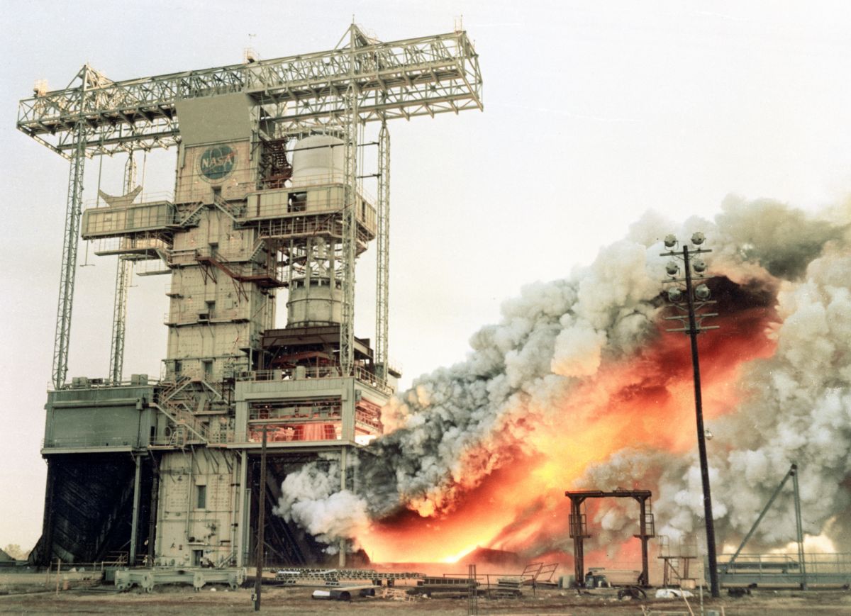
F-1 Under Test at MSFC
(NASA)
U.S. Manned Rocket Propulsion Evolution
Part 8.11: The Rocketdyne F-1 Engine
Compiled by Kimble D. McCutcheon
Published 13 May 2021; Revised 7 Dec 2022
F-1 Under Test at MSFC (NASA) |
The Saturn V could have never achieved its objective of sending humans to Earth’s moon were it not for the F-1 engine. When work on the F-1 began, the most powerful production rocket engine produced around 150,000 lbT. At a point when it was a major engineering accomplishment to increase engine thrust by only 10%, the idea of increasing the thrust of a single engine by a factor of 10 was absurd. But that is exactly what Rocketdyne and MSFC engineers accomplished. This was no easy task and there were some spectacular failures along the way, but by the time the Saturn V flew, F-1 engine performance was nearly flawless. |
Background
In 1955, USAF Propulsion Laboratory Engineers began wondering just how large a single-chamber liquid-propellant rocket engine could be. At that time thermonuclear weapons were the size of buildings and weighed scores of tons, so there were practical reasons for wondering such a thing. Rather than seeking a direct analytical answer to this question, they chose instead to select the largest thrust anyone could imagine and do the preliminary design for an engine that could achieve that thrust. They chose 1M lbT and, with the help of Rocketdyne, which was already looking into a 300,000 – 400,000 lbT engine, started work. Rocketdyne presented the results of this study to the Air Force in 1957 and the Air Force told Rocketdyne to go build one. It was to be called the F-1.
By 1959, Rocketdyne built an uncooled boilerplate engine and achieved short-duration but stable 1M lbT, but it was prone to rough starts and destructive combustion instability. Clearly, extensive development was going to be required. As the Air Force lost interest, the ABMA was absorbed by the newly-formed NASA in 1960 and NASA was very interested in the F-1, but wanted it to be bigger still.
Abraham "Abe" Silverstein, who had been director of the NACA Aircraft Engine Research Laboratory (later Lewis and now Glenn NASA Centers), had moved to NASA Headquarters in Washington, DC, where he was head of all development. Silverstein insisted that the F-1 should produce 1.5M lbT, same as the total thrust of the Saturn IB. He also insisted this should be accomplished by scaling up existing ballistic missile technology to produce a conservative design reliable enough for human flight.
Following these dictates, Rocketdyne followed the S-3D and H-1 proven examples in propellant choice (RP-1 and LOX), overall packaging, thrust chamber design, gas generator cycle, pressure ladder start sequence and using a heat exchanger to vaporize LOX and heat helium to pressurize the LOX and RP-1 tanks. The F-1 turbopump was a marked departure from the tried and true Mark 3 turbopump that had served Atlas, Thor, Jupiter and the H-1. The new turbopump eliminated the gearbox, placing the 3-foot diameter two-stage turbine, centrifugal fuel and centrifugal LOX pumps on a single shaft. The new pump also had dual symmetrical outlets on both the fuel and LOX pumps; this divided the total head rise load by two and reduced the duct and valve sizes. Fuel lubricated the turbopump bearings and powered the thrust vectoring system. But mostly the F-1 was just big, "a big, dumb engine" according to one Rocketdyne manager. Despite the F-1's dumbness, it operated at an unprecedented 1,125 psia chamber pressure, which resulted in many new details that had to be refined and many problems that had to be overcome.
Development
While the production F-1 was a very simple engine, its initial design was quite complex. The first design featured three turbopumps. A hydrazine pump required a hydrazine gas generator to run the hydrazine pump turbine. This same gas generator also powered a LOX turbopump and a fuel turbopump. All three pumps had their own lubrication system. This scheme was fortunately scrapped early before it was ever tested.
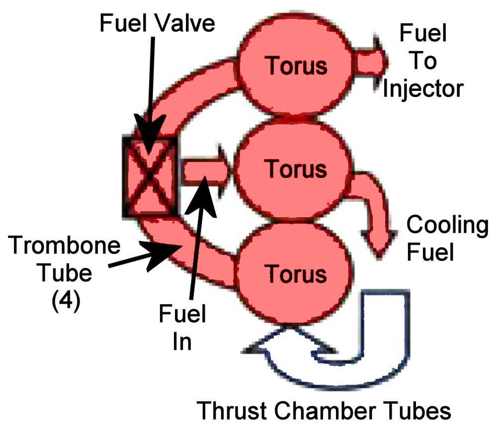
Another early design concept was troublesome. Called a triple manifold thrust chamber, it consisted of three torodial fuel manifolds stacked atop one other at the thrust chamber top. Fuel entered the middle manifold and traveled down half the thrust chamber tubes and up the other half to regeneratively cool the thrust chamber. It was then collected by the bottom torus, which was connected to the upper one by four large trombone tubes, each of which included a fuel valve. These trombone tubes entered the toruses tangentially, which set up a racetrack flow pattern with horrible pressure losses. This scheme actually did get tested but was replaced as soon as it was practical.
Combustion chamber pressure was another challenge. The F-1 design initially specified a 1,125 psi chamber pressure at a time when the only 520 psi had been successfully achieved.
 Combustion Instability Video |
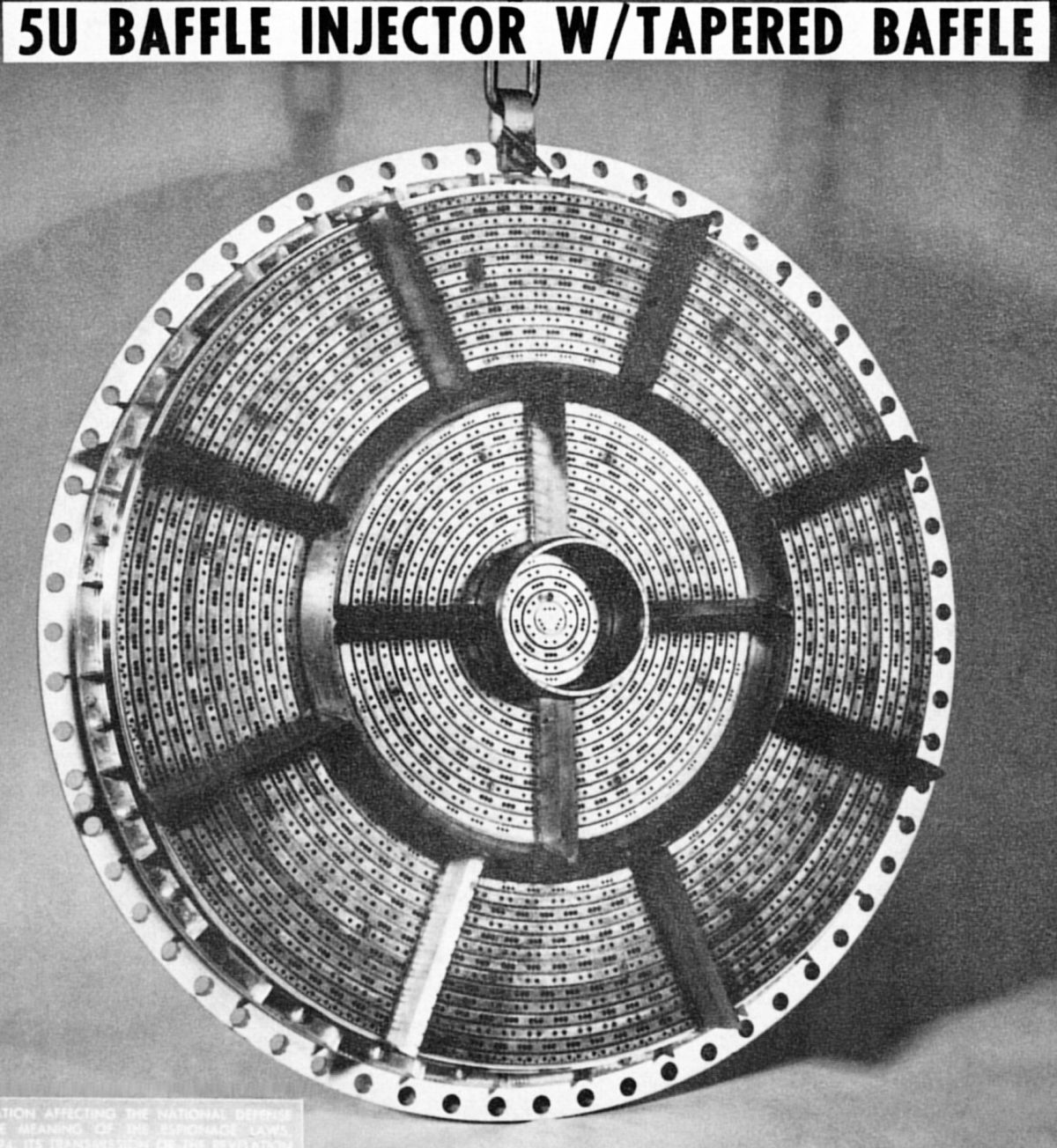
Rocketdyne spent the first year of F-1 development gradually increasing its thrust, aiming at a 1,522,000 lbT rating. Seven times, or about 10% of the time, when operating at thrust levels below 1M lbT, brief periods of combustion instability were noted. The test engine was fitted with a special rough combustion sensor that shut it down with little of no damage if instability was detected. At that point the injector was flat-faced and used like-on-like doublet impingement. The engine finally reached its full duration rated thrust on 26 May 1962.
But on 28 Jun 1962 disaster struck. According to F-1 engineer Robert Biggs, "A combustion disturbance occurred with unprecedented ferocity." Both fuel lines blew off the engine and the resulting LOX-rich operation burned up the engine, totally destroying it. Ten more such episodes followed, with each doing considerable damage; two of these led to complete engine destruction.
The F-1's problems now became front and center since there was no "plan B" for getting to the moon without the F-1. MSFC tasked Jerry Thompson, the head of its Liquid Fuel Engines Systems Branch, to head an ad hoc committee, “Project Go”, which included Paul Castenholz, Bob Levine, Dan Klute, and Bob Fontaine from Rocketdyne, plus a host of other scientists, engineers and combustion experts from all over the country. The Project Go team led a huge two-year effort to understand combustion instability and improve the injector. Rocketdyne embarked on an extensive test program that ran 2,000 tests on 210 different injector designs, consisting of 15 different baffle designs and 14 injector configurations. This process used high-speed high-frequency pressure instrumentation to discover the F-1's dominant acoustic modes. They eventually hit upon a combination injector configuration and baffle arrangement that did not exhibit spontaneous instability, but the question remained, "How can you be sure it won't happen again?" Rocketdyne addressed this by putting a small bomb in near the injector's center that exploded soon after the engine reached full thrust. The exploding bomb introduced instability, which the injector design damped out within 45 ms.
| Injector Pattern | Baffle | Injection Elements | Tests | |||
|---|---|---|---|---|---|---|
| Pattern | Compartnemts | Length | ||||
| 1) Modified 5U | Doublet | Doublet | 4 | |||
| b | 4 | 7.62 | Doublet | Doublet | 5 | |
| c | 9 | 7.62 | Doublet | Doublet | 2 | |
| e | 13 | 7.62 | Doublet | Doublet | 20 | |
| f | 13 | 7.62 | Doublet | Doublet | 1307 | |
| f | 13 | 15.2 | Doublet | Doublet | 1 | |
| g | 21 | 7.62 | Doublet | Doublet | 4 | |
| k | 53 | 7.62 | Doublet | Doublet | 1 | |
| 2) 5U | Doublet | Triplet | 19 | |||
| a | 3 | 7.62 | Doublet | Triplet | 35 | |
| e | 13 | 7.62 | Doublet | Triplet | 350 | |
| e | 13 | 15.2 | Doublet | Triplet | 1 | |
| e | 13 | 25.4 | Doublet | Triplet | 1 | |
| f | 13 | 7.62 | Doublet | Triplet | 101 | |
| 3) Radially Aligned | f | 13 | 7.62 | Doublet | Doublet | 19 |
| g | 21 | 7.62 | Doublet | Doublet | 1 | |
| i | 25 | 7.62 | Doublet | Doublet | 33 | |
| i | 25 | 7.62 | Doublet | Triplet | 7 | |
| 4) Double-Row Cluster | e | 13 | 7.62 | Doublet | Triplet | 5 |
| i | 13 | 7.62 | Showerhead | Triplet | 2 | |
| i | 25 | 7.62 | Doublet | Triplet | 9 | |
| 5) Single-Row Fuel, Double-Row LOX | e | 13 | 7.62 | Doublet | Triplet | 4 |
| 6) H-1 | f | 13 | 7.62 | Doublet | Triplet | 4 |
| 7) Reverse 5U | e | 13 | 7.62 | Doublet | Triplet | 2 |
| 8) Rotated Fan | d | 11 | 7.62 | Doublet | Doublet | 2 |
| 9) Spray Nozzle | f | 13 | 7.62 | Nozzle | Nozzle | 2 |
| 10) Single-Row Fuel, Single-Row LOX | f | 13 | 7.62 | Doublet | Doublet | 13 |
| f | 81 | 7.62 | Doublet | Triplet | 1 | |
| 11) Splash Ring | Showerhead | Triplet | 2 | |||
| 12) Shielded Stream | Doublet | Triplet | 1 | |||
| 13) O-F-O Triplet | 1 | |||||
| 14) Coaxial | h | 21 | 7.62 | 17 | ||
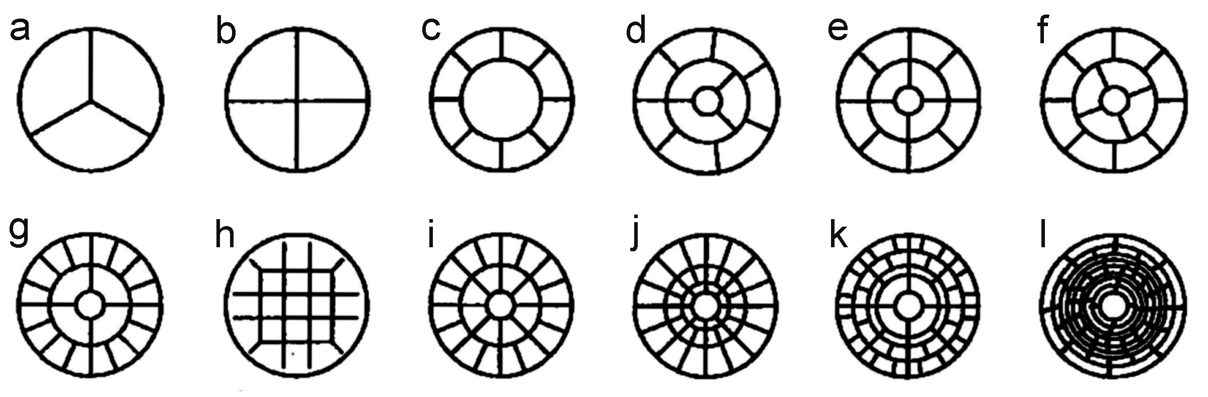 |
| F-1 Baffle Patterns Investigated |
 |
 |
 |
 |
 |
| Early 5U(f) Doublet/Triplet Injector (heriocrelics.org) |
Injector Baffle Coolant Flow (heriocrelics.org) |
Injector Baffle Cross Sections (heriocrelics.org) |
Flight Injector Configuration | Flight Injector Specifications |
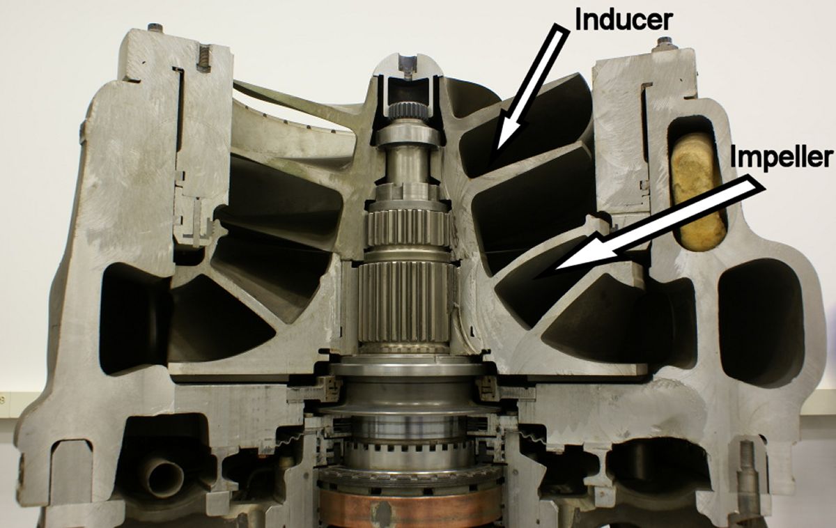
The turbopump also presented development challenges. LOX pump failures resulted in explosive fires that converted failed components into ions. Engineers scrutinized the LOX pump seals and bearings, but the failures persisted. Finally, on 18 Nov 1963, an engine under test at MSFC failed but did not catch fire. Disassembly revealed that one of the six LOX pump impeller vanes had had broken loose, but stuck inside the impeller instead of rubbing and causing a fire. The F-1 LOX impeller had been scaled up from a previous design and the new, larger impeller was subjected to much higher loads. The four destructive LOX pump failures had happened at 110, 110.5, 107.7 and 109 sec; this looked statistically significant, but after much study the team wrote it off to a freak coincidence. Rocketdyne beefed up the impeller vanes, made changes to eliminate fretting and set a 3,500 sec life-limit on impellers used for ground testing. Flight engines never got up above 800 sec. Although Rocketdyne solved the LOX pump problem, the people familiar with the engine would cringe when 110 seconds went by and, then, breathe again.
In addition to the LOX fires the turbopump suffered through other growing pains. Cracks in the high-nickel René 41 alloy turbine housing were traced to an improper welding process. Gradually the metal fatigue, clearance and process problems were systematically eliminated, helping the F-1 achieve unprecedented reliability.
 |
 |
 |
 |
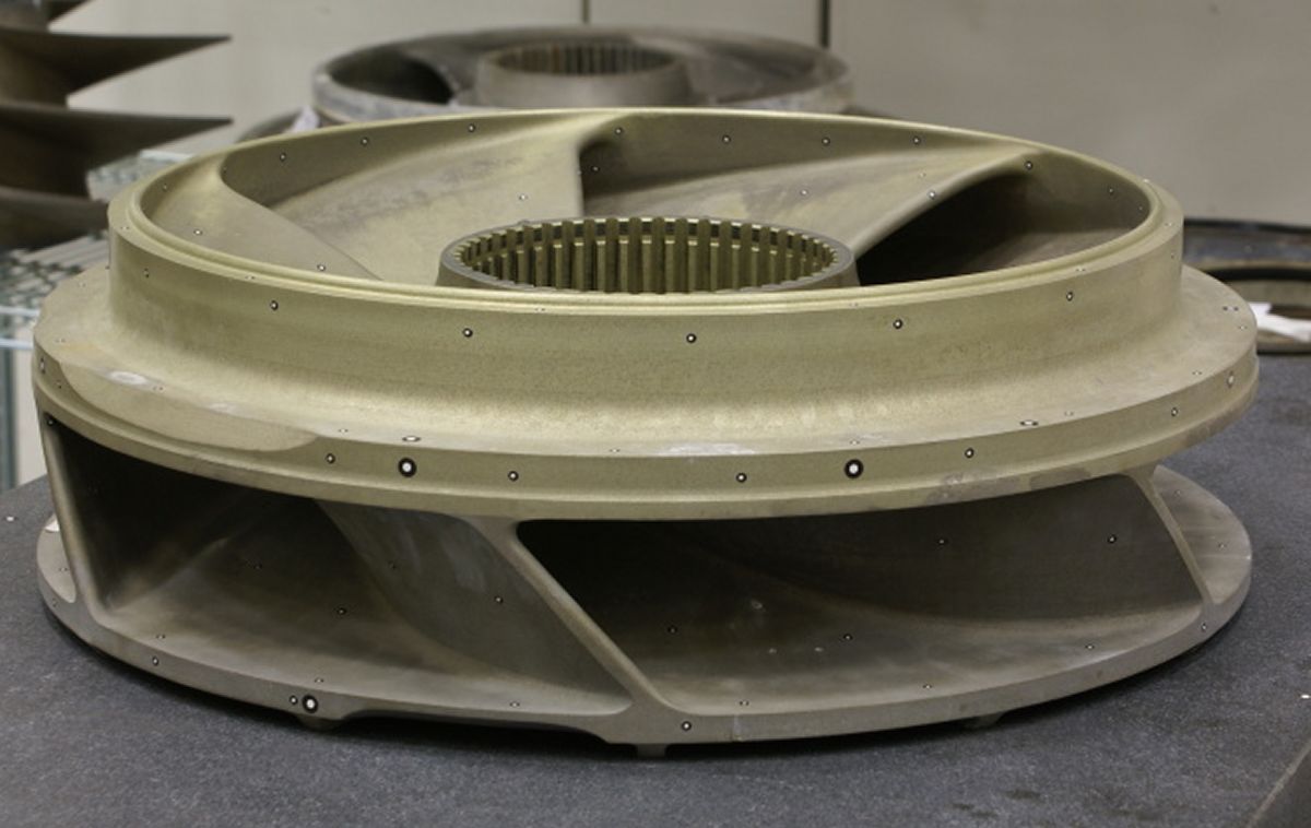 |
| LOX Pump Cutaway (heriocrelics.org) |
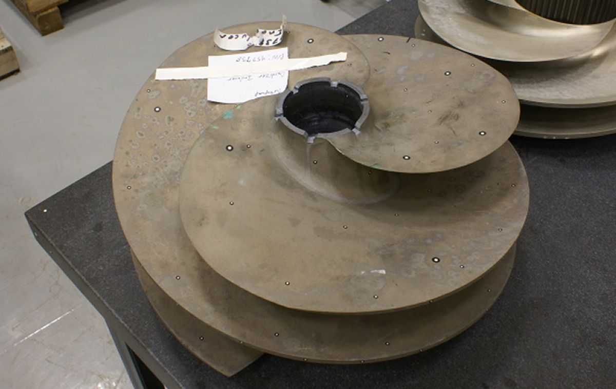
LOX Pump Inducer (heriocrelics.org) |
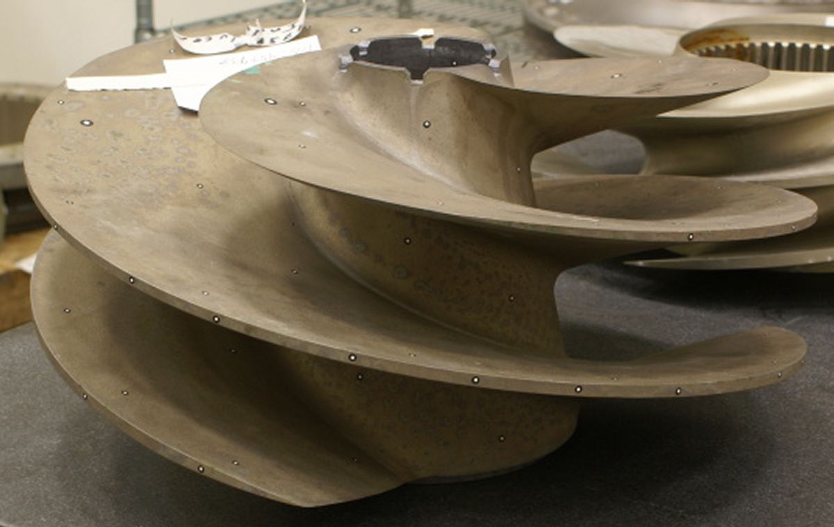
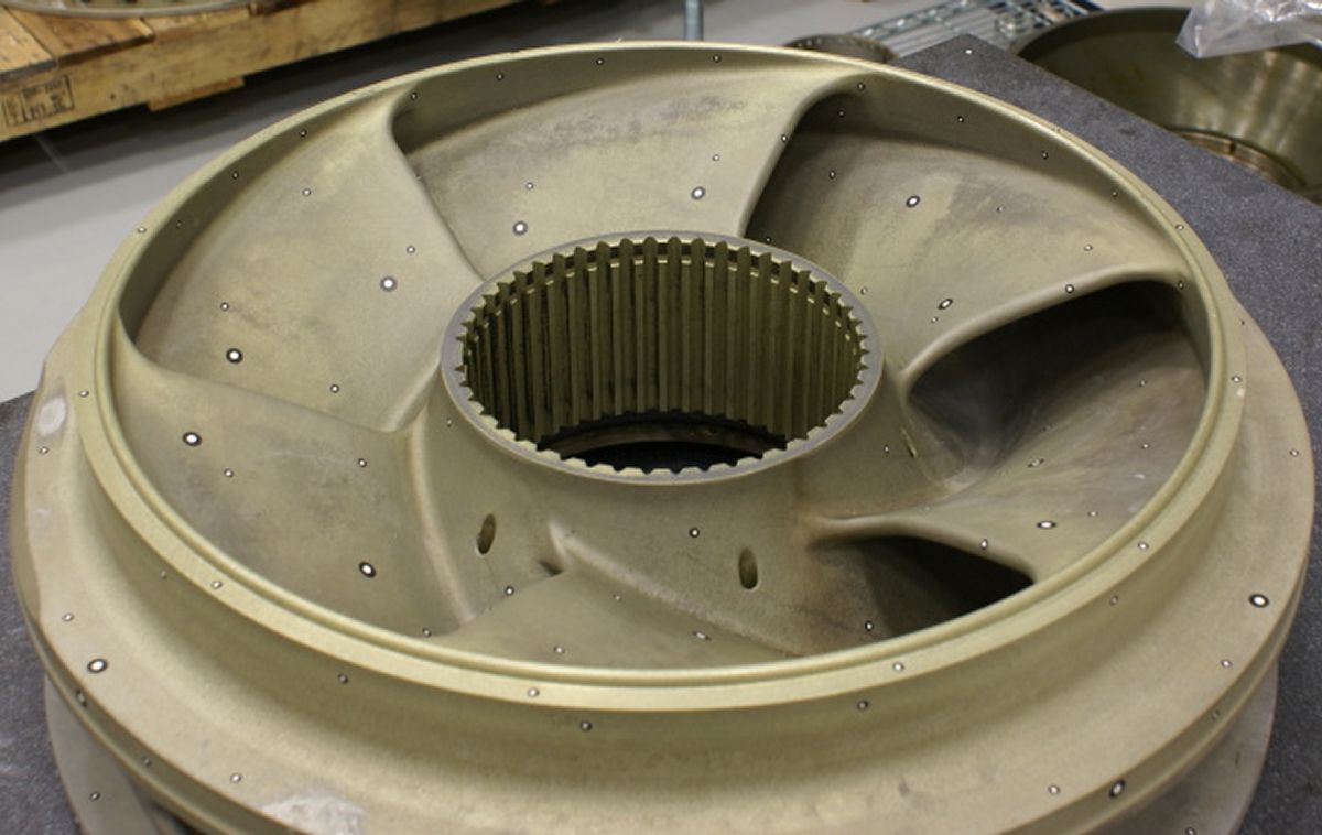
LOX Pump Impeller (heriocrelics.org) |
||
Legacy
Robert Biggs, who in November 1967 was at the window in Firing Room 2, three miles away from the first Saturn V launch, commented, "I considered that the highpoint of my career. I’ve never had such a feeling of pride, just watching the thing go up and imagining that the earth was trembling. The glass window in front of me was moving inches. It was quite an experience."
Rocketdyne built 98 production F-1s, 70 of which were tested in S-ICs. The 12 Apollo flights used 60 engines and Skylab used another 5. These 65 flight engines were all 100% successful.
Rocketdyne ran six engines for more than 5,000 sec. At every opportunity, they encouraged "all-up" acceptance testing. Each F-1 was tested individually for a 40-sec calibration run and a 165-sec mission duration test. Then five F-1s were tested together on an S-IC stage for 125 sec. Acceptance testing took a total of 495 sec, for a mission duration of 165 sec. The highest-time engine ran a total of 800 sec.
The first three S-ICs were tested at MSFC; the remainder at NASA’s John C. Stennis Space Center near Bay St. Louis, Mississippi.
| Engine | Model 39 | Rocketdyne 75-110-A-7 | Rocketdyne LR89-5 | Rocketdyne LR105-5 | Aerojet LR87-AJ-7 | Aerojet LR91-AJ-7 | Rocketdyne H-1D | Rocketdyne F-1 |
|---|---|---|---|---|---|---|---|---|
| Used In | German V-2 | Redstone | Atlas E, F Booster | Atlas E, F Sustainer | Titan GLV Stage 1 | Titan GLV Stage 2 | Saturn I, IB | Saturn S-IC |
| Era | 1943 | 1953 | 1960 | 1960 | 1962 | 1962 | 1961 | 1964 |
| Thrust, SL (lb) | 55,000 | 82,977 | 163,211 | 60,473 | 212,827 | 50,627 | 204,300 | 1,522,000 |
| Thrust, Vac (lb) | ? | 93,565 | 184,905 | 86,866 | 244,165 | 100,000 | 213,051 | 1,748,200 |
| Burn Time (sec) | 60 | 155 | 135 | 430 | 139 | 180 | 150 | 165 |
| Chamber Pressure (psi) | 218 – 239 | 318 | 580 | 696 | 784 | 804 | 701 | 1,125 |
| Specific Impulse (sec) | 203 – 239 | 235 – 265 | 248 – 282 | 220 –316 | 258 – 296 | 160 – 316 | 255 – 289 | 265.4 – 304.1 |
| Propellant Flow (gps) | 33.5 | 41.3 | 47.7 | 20 | 81.3 | 26.9 | 93.5 | 674 |
| Propellant Flow (lb/sec) | 286 | 355 | 458 | 193.2 | 824 | 322 | 760 | 5,785 |
| Nozzle Expansion Ratio | 2.83 | 3.61 | 8 | 25 | 8 | 45 | 8 | 16 |
| Engine Weight (lb) | 2,484 | 1,479 | 1,580 | 1,010 | 1,571 | 1,245 | 1,399 | 18,500 |
| Thrust / Weight, SL | 22 | 56 | 103 | 60 | 136 | 80 | 146 | 81 |
| Fuel | 75% Ethanol | 75% Ethanol | RP-1 | RP-1 | A-50 | A-50 | RP-1 | RP-1 |
| Oxidizer | LOX | LOX | LOX | LOX | N2O4 | N2O4 | LOX | LOX |
| Mixture Ratio (Ox/Fuel) | 1.13 | 1.324 | 2.21 | 2.25 | 1.9 | 1.79 | 2.34 | 2.27 |
| Turbopump Output (hp) | 580 | 758 | 3,140 | 1,663 | 5,180 | 2,122 | 4,021 | 55,000 |
| Turbine RPM | 3,800 | 4,718 | 30,986 | 30,000 | 25,172 | 23,685 | 6,680 | 5,488 |
References
Biggs, Robert. "Rocketdyne F-1: Saturn V First Stage Engine" in Remembering the Giants: Apollo Rocket Propulsion Development, ed. Steven C. Fisher and Shamin A. Rahman, NASA SP-2009-4545 (Washington, DC: NASA History Division, Dec 2009).
F-1 Engine Familiarization Training Manual, R-3896-1 (Canoga Park, CA: Rocketdyne – North American Rockwell, 31 Mar 1967).
Hunley, J.D. Technology for U.S. Space-Launch Vehicles, 1926 – 1991 (College Station, Texas: Texas A&M University Press, 2007).
Kraemer, Robert S. Rocketdyne: Powering Humans into Space (Reston, Virginia: AIAA, 2006).
Oefelein, Joseph C. and Vigor Yang "Comprehensive Review of Liquid-Propellant Combustion Instabilities in F-1 Engines" Journal of Propulsion and Power (Reston, VA: American Institute of Aeronautics and Astronautics, Vol. 9, No. 5, Sep-Oct 1993).
--- One Second in the Life of the Rocketdyne F-1 Rocket Engine, by Tom Fey ---
--- On To Part 8.12 - Description ---
Send mail to
![]() with questions or comments about this web site.
with questions or comments about this web site.
![]()