Apollo Pad
Abort Test
U.S. Manned Rocket Propulsion Evolution
Part 9.10: The Apollo Launch Escape System
Compiled by Kimble D. McCutcheon
Published 20 Sep 2021; Revised 4 Aug 2022
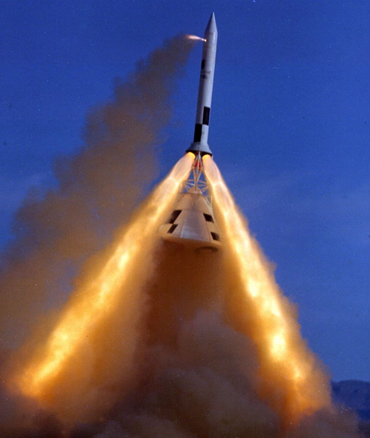
Apollo Pad Abort Test |
The Launch Escape System (LES) was designed to distance the command module (CM) from the launch vehicle (LV) if a pad or first-stage launch emergency occurred. The LES lofted the CM away from the LV and out over the Atlantic Ocean, to an altitude that alowed an otherwise normal ocean or earth landing. There were number of abort conditions, but the LES was primarily intended to address explosions on or near the launch pad, first-stage engine hard-overs, and first-stage engine failure during the first ~30 seconds of flight. Astronauts could manually activate the LES while on the launch pad and at any time after launch up to the jettison altitude; it was automatically activated by the emergency detection system (EDS) during the first 100 seconds of flight. |
LES Description
The 8,000 lb LES was 33 feet long and had a maximum diameter of about 4 feet. The LES, top-to-bottom, consisted of an instrumentation package (Q-ball), nose cone, canards, ballast compartment, pitch control motor, tower jettison motor, launch escape motor, tower and boost protective cover.
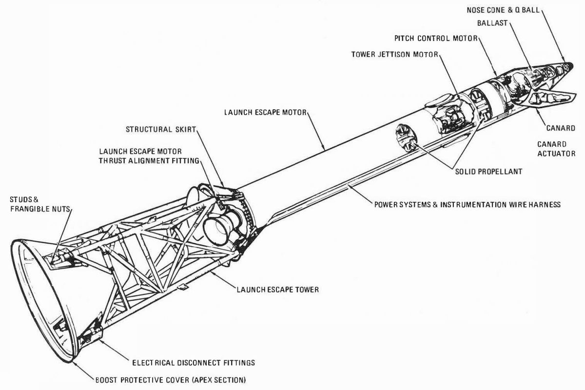 |
| Apollo Launch Escape System |
 |
 |
| Q-ball and Nose Cone | Canards |
The Q-ball had eight static ports that were connected to differential pressure transducers and electronic modules. It measured dynamic pressure differentials about the pitch and yaw axes in order to monitor vehicle angle-of-attack and dynamic pressure. These were displayed on a CM angle-of-attack indicator, sent to the LV guidance system, and telemetered to the ground. The angle-of-attack information provided a basis for crew abort decisions in the event of slow LV divergence.
The Inconel nose cone was 13.37" long and 13.3" in diameter. Just below the nose cone, a tapered ballast compartment contained lead and depleted uranium weights that ensured stable LES behavior at all velocities and operating modes.
The canards were two metallic clamshell aerodynamic control surfaces, about 4 feet long, that oriented the command module with the heat shield forward and parachutes aft. They deployed and via a gas-powered actuator to fixed positions 11 seconds after abort initiation and mechanically locked in place once fully open.
 |
 |
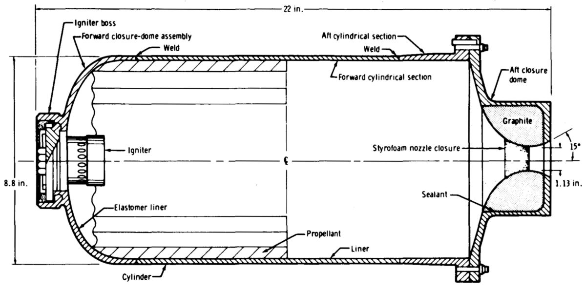
| Pitch Control Motor | Igniter |
The pitch control motor pushed the LES and CM toward the Atlantic Ocean and away from the LV during a low-altitude abort. Built by the Lockheed Propulsion Co. of Redlands, California, it was 22" long, 8.75" in diameter, weighed 49 lb (8.9 of which was propellant), and produced 2,420 lbT for 0.62 sec. The propellant was integrally cast as a 14-point internal burning star configuration. Total impulse was controlled by varying the propellant grain length.
Pitch control motor ignition was via an pellet-basket-type igniter assembly with two pyrotechnic igniter cartridges, each of which had a booster charge and Apollo standard hot-bridgewire initiator. Identical igniters were used in the launch escape and tower jettison motors.
 |
| Tower Jettison Motor |
The TE-M-380 tower jettison motor was used in all missions to jettison the LES. Built by the Thiokol Chemical Corp. of Elkton, Maryland, the jettison motor was 55.6" long, 26" in diameter, weighed 525 lb (205 of which was propellant, integrally cast in a 10-point double-web internal burning star configuration), and produced 31,500 lbT for 1.1 sec. The motor had two fixed nozzles, located 180° apart, that projected downward and outward, producing a thrust vector of about 4° that tipped the LES and pulled it free of the CM.
 |
| Launch Escape Motor |
The launch escape motor, built by the Lockheed Propulsion Co. of Redlands, California, was 186" long, 26" in diameter, weighed 4,794 lb (3,162 of which was propellant, integrally cast in an 8-point internal-burning star configuration), and produced 138,300 lbT for 3.3 sec at sea level. This was enough impulse to carry the 13,000 lb CM about a mile from the LV. In order to provide a thrust vector angle of about 2.15° relative to the center of gravity excursion line, one of the two pitch-plane nozzle throat areas was about 5% larger than the yaw plane nozzles, while the other pitch-plane nozzle throat area was about 5% less than the yaw plane nozzles. The titanium motor skirt attached the motor stack to the tower.
The launch escape tower was a welded titanium tubing truss structure, about 10 feet long, 3 feet square at the top and 4 feet square at its base, and weighed about 500 lb. Its 2.5" and 3.5" titanium tubes were covered with Buna -N rubber insulation, which protected it from the rocket motor exhaust. The four tower legs fit into wells in the CM forward structure and were fastened with studs and frangible explosive nuts that facilitated LES/CM separation.
The boost protective cover was attached to the launch escape tower base. Impregnated fiberglass, honeycomb-cored laminated fiberglass, and cork layers comprised the boost protective cover's structure. It had 12" blowout ports for reaction control motors, vents, and an 8" diameter window that coincided with the CM hatch window. The cover protected the CM from LES rocket exhaust and also from atmospheric heating during launch. It was 11 feet tall, 13 feet in diameter, and weighed about 100 lb.
Normal Operation
 |
 |
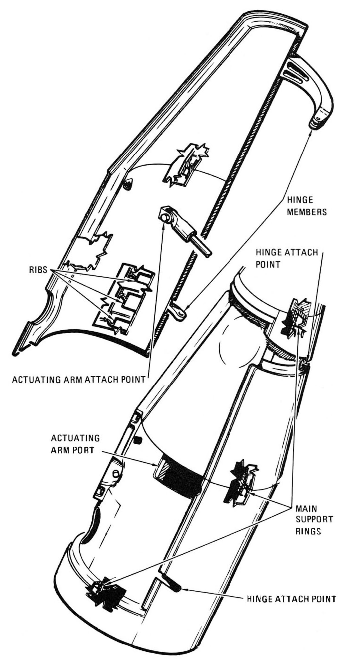
| LES Jettison | LES Attachment |
During successful launches, astronauts jettisoned the LES at a prescribed altitude, typically about 30 seconds after second-stage ignition. The boost cover apex section was attached to the launch escape tower legs. A passive tension tie connected the boost cover apex and the CM docking probe. During a normal launch, the tower jettison motor pulled the cover away and snapped this tension tie, leaving the probe with the command module.
If an abort became necessary after the LES was jettisoned, it was performed with the SM SPS. Abort initiation automatically separated the spacecraft from the LV, SM reaction control engines fired to settle propellants so that they flowed properly, and the service propulsion engine ignited to distance the spacecraft from the LV.
Abort Operation
Two master events sequence controllers, each containing time delays, relays, fuses, and fusistors, were located in the CM forward right equipment bay. They controlled numerous launch abort functions along with numerous normal mission functions.
During an abort, the master events sequence controller and the lunar docking events sequence controller sent signals that fired ordnance devices that cleaved the docking ring from the CM. When the launch escape assembly was jettisoned after an abort the tension tie pulled the docking probe and docking ring away with the boost protective cover.
Once launched, the first-stage booster could not be shut down for the first seconds of flight (30 sec for the Saturn V; 40 sec for the Saturn IB); this was a range safety consideration. Thereafter, if an abort signal was received, the booster was cut off. In either case the CM-SM separation charges fired, and the launch escape motor ignited. The launch escape motor lifted the CM away from the LV; at low altitudes the pitch control motor also fired, directing the flight path off to the side.
Two canards were automatically deployed 11 seconds after the abort sequence began. Aerodynamic forces acting on the canards turned the CM so that its blunt end was forward. Three seconds later on extreme low altitude aborts, or at about 24,000 feet on high-altitude aborts, tower separation devices released the LES from the CM and the jettison motor was fired, carrying the LES away from the CM's landing trajectory.
The LES was nominally jettisoned after second stage ignition. Normally both CM tower jettison switches were used to initiate this function; however, either one initiated the tower jettison circuits. The frangible nut assemblies that attached the tower legs to the CM each included two detonators that fired at jettison switch activation. The tower jettison circuits also ignited the tower jettison motor. The crew used cues to initiate tower jettison; these were the number one engine status light for the Saturn IB and the "S-II Sep" light for the Saturn V. The crew used the digital events timer in conjunction with the visual light cues to jettison the tower at the correct time. If the tower jettison motor failed to ignite, the launch escape motor was used to jettison the tower. After the LES was jettisoned, the EDS automatic abort circuits were disabled.
Abort procedures fell into several categories termed modes. Mode 1 aborts were those using the launch escape subsystem; Modes 2, 3, and 4 aborts were those using the service propulsion subsystem. There were subdivisions within each category, principally due to the spacecraft altitude at abort time. Only Mode 1 Aborts, i.e., those involving the LES are discussed here.
The sequence differed slightly for high-altitude LES aborts; the pitch control motor was not fired, CM reaction control propellant dumping followed the normal entry procedure (during descent on the main parachutes), and the reaction jet engine control was not cut off (enabling the stabilization and control subsystem to control the CM's attitude automatically).
 |
 |
| Abort Sequence as a Function of Altitude | Abort Modes |
Manual Abort
A manual abort could be initiated before or during launch by the commander's translation control located on his couch arm. In a pad abort the LES carried the CM to an altitude of about 4,000 feet before it was jettisoned.
Automatic Abort
The emergency detection system (EDS) operated from LV umbilical separation until 100 seconds after liftoff. It was designed to detect LV emergency conditions, display the information to the astronauts, and if the system was on automatic, start an abort sequence. Under conditions of excessive vehicle roll, pitch or yaw rates, or two booster engines out, the EDS initiated an abort signal. This signal reset the event timer, activated the LES, and after 30 to 40 seconds of flight, cut off the LV engines. A lockout scheme prevented the EDS from operating before liftoff.
The EDS monitored critical LV conditions during powered flight. Emergency conditions displayed on the crew's main display console indicated necessity for abort. The system provided for a crew-initiated abort with the use of the launch escape subsystem or with the service propulsion subsystem after tower jettison. The crew could initiate an abort during countdown until normal spacecraft separation from the LV. An automatic abort could be initiated in case of time-critical conditions, including loss of LV engine thrust on two or more engines and excessive vehicle roll, pitch or yaw rates.
When either a manual or automatic abort was initiated the EDS cut off the booster engines except during the first 40 seconds of flight (Saturn IB) or the first 30 seconds of flight (Saturn V); range safety requirements imposed these time restrictions.
The EDS automatic abort circuits were automatically activated at liftoff and deactivated 100 seconds after liftoff. Switches on the main display console deactivated the entire automatic abort capability or the "two engines out" and "excessive rates" portions of the system independently. These three switches were placed in the automatic position before liftoff and were switched off before first stage separation. The two automatic abort circuits also were deactivated automatically by the IU just before the first stage inboard engine cutoff as a backup to manual deactivation.
Electrical circuits in the IU controlled the LV status lights. The "LV Rate" light illuminated when LV roll, pitch, or yaw rates were in excess of predetermined limits. The red "LV Guid" light indicated loss of attitude reference in the guidance unit. The yellow "LV Engines" lights illuminated when an engine was developing less than the required thrust. The engine lights provided four cues: ignition, cutoff, engine below thrust, and physical stage separation. A yellow "S-II Sep" light illuminated at second stage first-plane separation and was extinguished at second-plane separation on Saturn V vehicles.
The "Abort" light was a red lamp assembly containing four bulbs that provide high-intensity illumination. This light was illuminated if an abort was requested by the launch control center for a pad abort or an abort during liftoff via up-data link. The "Abort" light could also be illuminated after liftoff by the range safety officer, or via the up-data link from the manned spacecraft flight network.
Conclusion
The LES appears simple at first inspection, but this impression belies its importance as the path of last resort to save crew lives. The LES was subjected to over 3,000 hrs of wind tunnel testing. Each of the three rocket motors underwent numerous qualification tests, including temperature cycling and vibration testing, temperature cycling and impact testing, accelerated aging, acceleration testing, and temperature-cycle testing.
In addition to component testing, the LES underwent seven full-up tests, including two pad-abort tests and five flight tests. The pad abort tests demonstrated aerodynamic stability, the ability of the LES to propel a CM a safe distance from the LV, proper pitch-control-motor, canard, and tower jettison functionality. Flight tests were performed at the White Sands Missile Range in New Mexico, used a Little Joe II rocket as a launch vehicle. These demonstrated reliable LES operation under critical flight conditions, along with earth landing system reliability and structural integrity. The flight test series first qualified the Little Joe II and then successfully demonstrated transonic abort at high dynamic pressure, abort at maximum dynamic pressure, high-altitude abort, and power-on tumbling boundary abort.
No LES was ever needed during the Apollo Program, but it was a great comfort for all involved to know it was there if needed.
References
Hyle, Charles T., Charles E. Foggatt, Bobbie D. Weber. Apollo Experience Report – Abort Planning (Houston, Texas: Manned Spacecraft Center, Jun 1972).
McCarthy Jr., J.F, J. Ian Dodds, R.S. Crowder. "Development of the Apollo Launch Escape System" AIAA Journal of Spacecraft Vol. 5. No. 8 (Downey, California: North American Rockwell Corp., Aug 1968).
Townsend, Neil A. Apollo Experience Report – Launch Escape Propulsion Subsystem (Houston, Texas: Manned Spacecraft Center, Mar 1973).
--- On to Part 9.20, The Apollo Command Module ---
Send mail to
![]() with questions or comments about this web site.
with questions or comments about this web site.
![]()