USSRC LMDE
U.S. Manned Rocket Propulsion Evolution
Part 9.42: TRW Lunar Module Descent Engine (LMDE)
Compiled by Kimble D. McCutcheon
Published 28 Dec 2021; Revised 4 Aug 2022
USSRC LMDE |
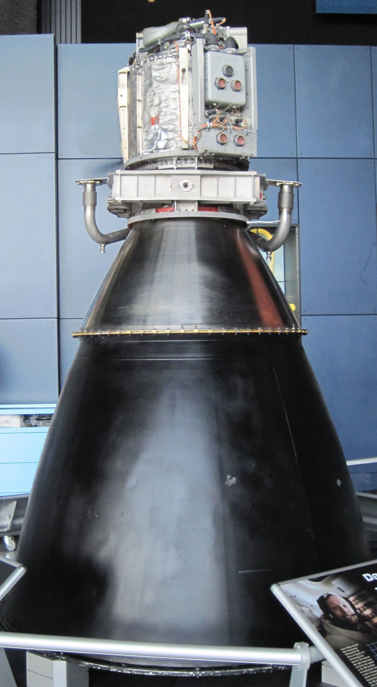
The TRW Lunar Module Descent Engine (LMDE, VTR-10) was a pressure-fed, variable thrust, gimbaling, liquid-propellant rocket engine with a 9,850 lbT maximum nominal thrust. It used throttleable variable-area cavitating venturi flow control valves mechanically linked to a variable area injector. Its storable hypergolic Aerozine 50 fuel and nitrogen tetroxide oxidizer contributed to its sterling performance and reliability record. |
Introduction
| ||||||||||||||||||||||||||||||||
Gerard "Jerry" W. Elverum began working at California Institute of Technology's Jet Propulsion Laboratory (JPL) in 1949, where he spent ten years doing pioneering research on propellants and rocket propulsion. In 1959, he joined Space Technology Laboratories (STL, later TRW). In May 1963, Grumman and NASA selected his patented deep-throttling design as a backup LM descent engine against competitors Aerojet and Reaction Motors. Then in December 1964, NASA selected the STL design as primary. Grumman received the first flight engine in August 1966. Elverum was program director and chief engineer for the LMDE throughout this time. He retired as vice president and general manager of TRW's Applied Technology Division in 1990.
At JPL, Elverum had experimented with concentric capillary tubes in order to make an injector that produced stable combustion. At STL, he hit on the idea of using cavitating venturi valves in conjunction with a variable-area injector to get stable and efficient combustion in a deeply-throttled rocket engine burning hydrazine and nitrogen tetroxide. Cavitating venturis lower fluid pressure to its vapor pressure, producing tiny bubbles at the venturi throat that choke and fix the flow irrespective of downstream conditions and pressure fluctuations. Elverum's genius was realizing that by making the cavitating venturi area variable with a central contoured pintle he could tailor the fuel and oxidizer flow rates to a specific throttle setting. This, in conjunction with a mechanically-linked concentric sleeve within the injector that moved in concert with the cavitating venturi contoured pintles, made a rocket engine that was stable and efficient at all throttle settings (US patent 3,205,656).
Description
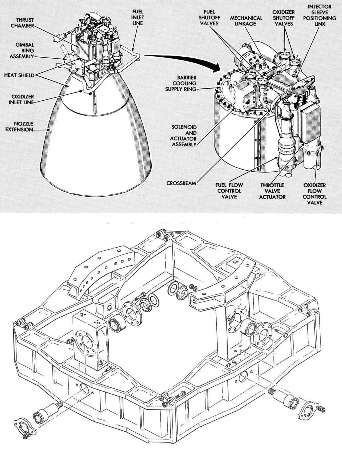
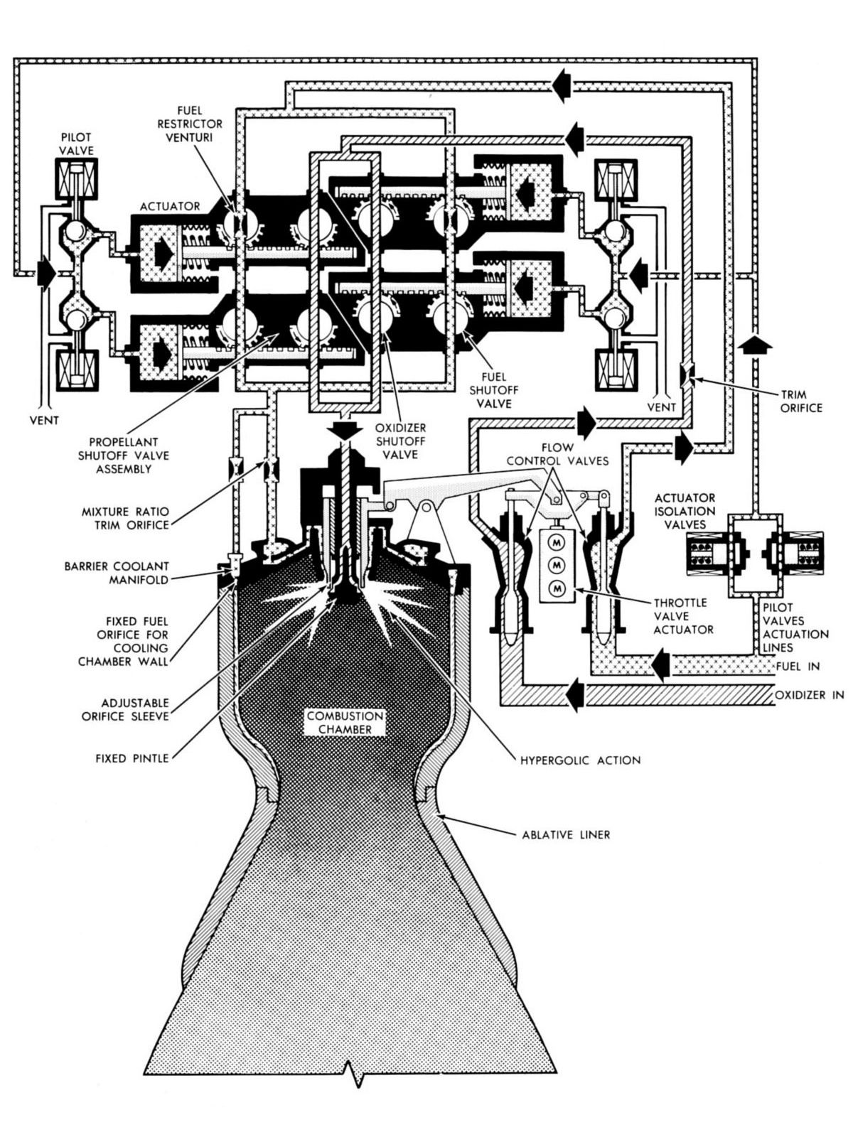
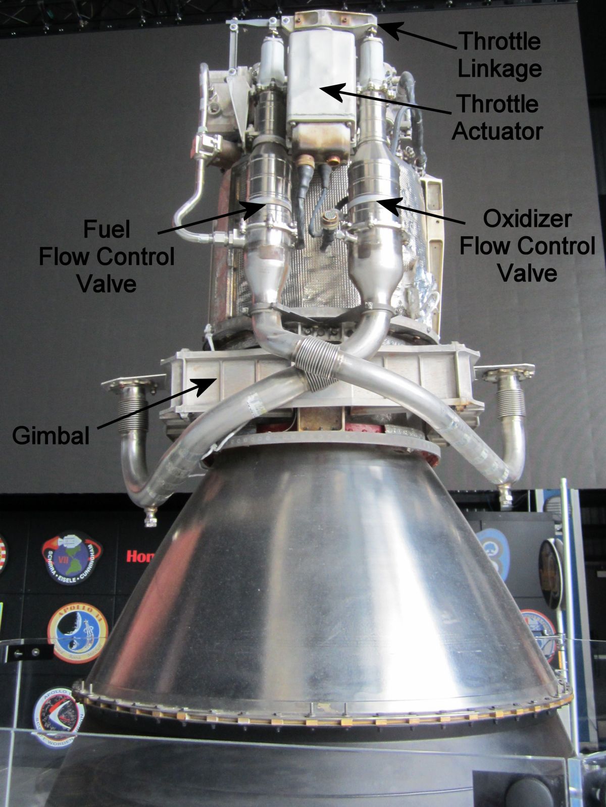
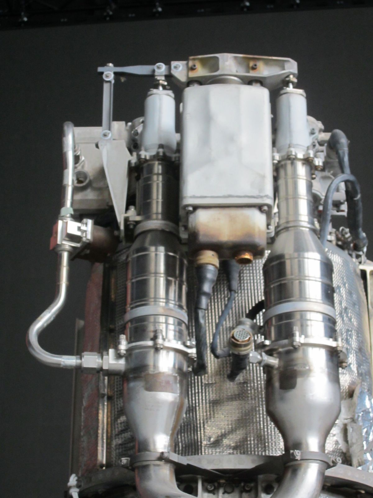
The LMDE was a compact package that interfaced with the LM via a gimbal frame that provided pitch and yaw thrust vectoring. LMDE propellants were supplied through two stainless steel propellant inlet lines with a simple bolted flange interface joint. The inlet lines accommodated the gimbal motion by means of a two flexible bellows welded in the lines at their gimbal axes intersections. Propellants flowed from the lines through cavitating venturi flow control valves to quad-redundant ball shutoff valves and to the head-end manifold. Most fuel was injected axially into the combustion chamber through the variable area concentric injector's annular orifice, while the remainder exited via a 36-hole barrier cooling ring along the chamber wall. This cost about 1.5% in performance but allowed the engine to run for 1,000 seconds, which was a VERY long time. Oxidizer entered the injector assembly center, where it was directed into the combustion chamber radially through 36 variable-area ports, forming 36 jets that impinged upon and ignited the conical fuel sheet.
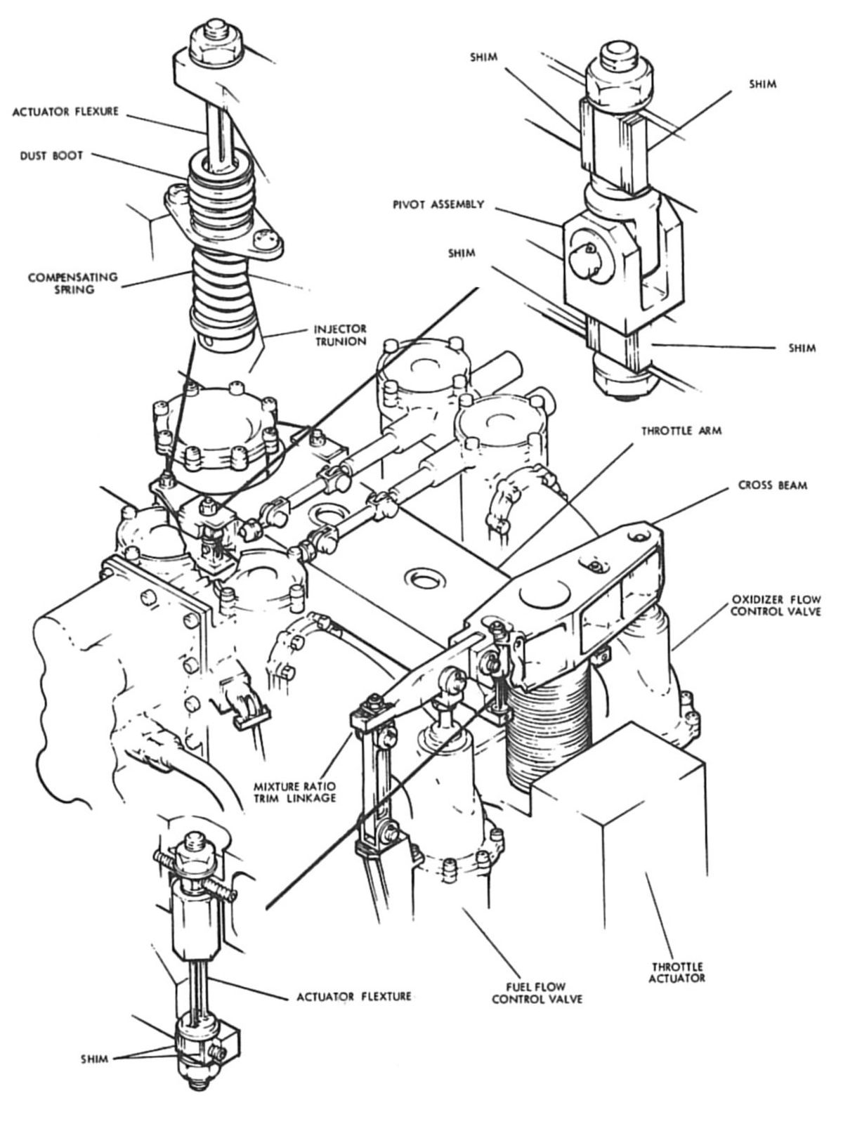
Thrust control was achieved by adjusting the propellant flow rates and varying the injection port area to maintain near uniform propellant velocities. An electromechanical throttle actuator converted LM electrical control signals to a linear actuator jackscrew position. Attached to the jackscrew top was a cross beam whose right side was connected directly to the oxidizer flow control valve through a flexural element, and whose left side was connected to the fuel flow control valve through a mixture ratio trim linkage, establishing the desired fuel flow control valve motion relative to the oxidizer flow control valve motion. This produced the required propellant mixture ratio and was adjusted during engine acceptance tests. Also attached to the cross arm by means of two flexures was a walking beam, pivoted off the manifold assembly, which translated motion from the throttle actuator assembly to the injector assembly. Motion of the injector's movable sleeve simultaneously changed the fuel orifice gap and the oxidizer outlet port sizes. The injector was spring loaded against the actuator and mechanism so that if electrical power was lost the engine automatically went to full-thrust. The manifold assembly, which provided throttle mechanism mounting points, was the propellant distribution network and the combustion chamber head-end closure.
 |
 |
 |
 |
 |
| Components | Head-End, Gimbal | Throttle Linkage | Flow Diagram | Actuators: Throttle, Gimbal |
 |
 |
 |
 |
 |
 |
Combustion Chamber
 |
| Combustion Chamber Section |
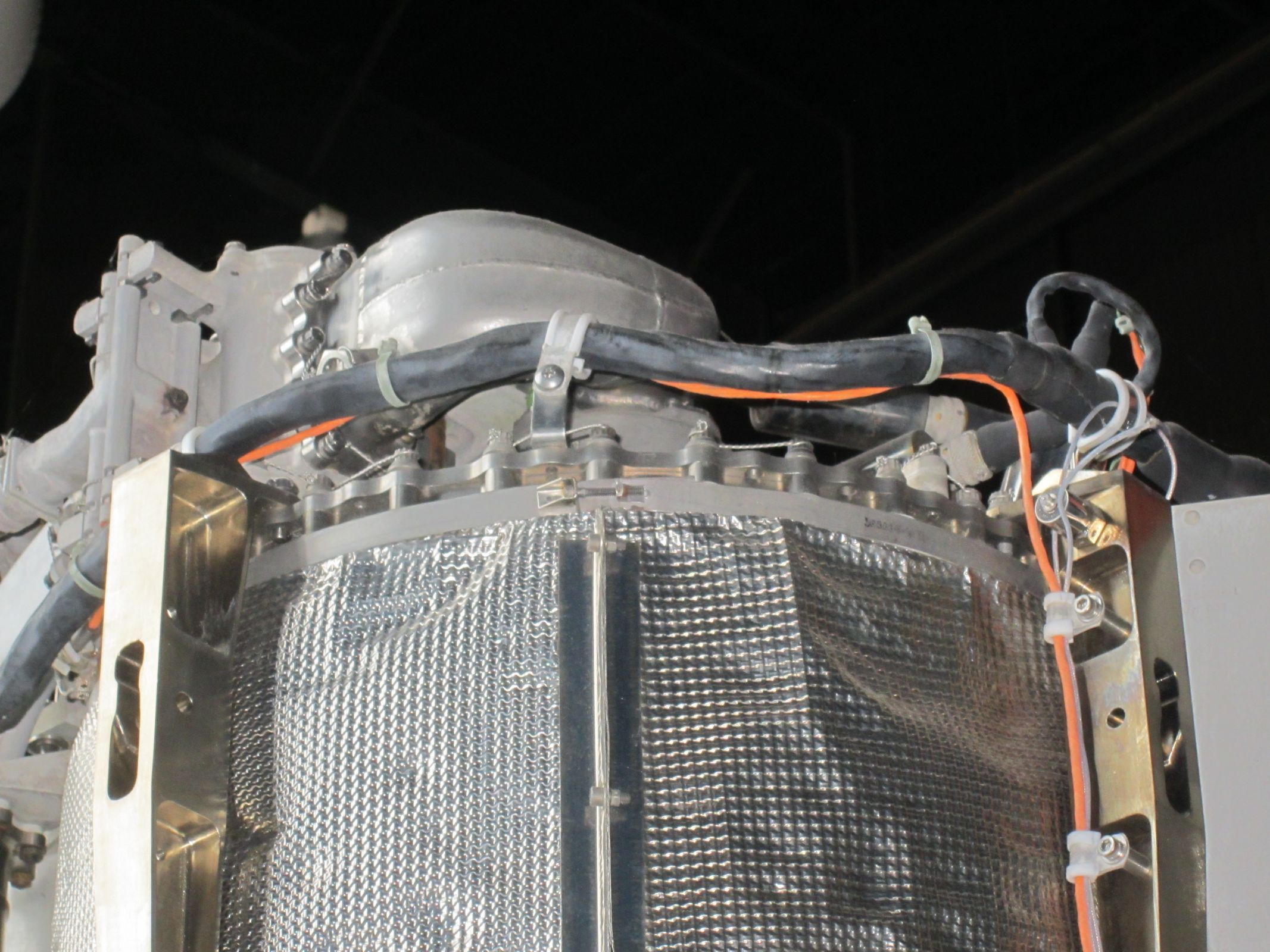
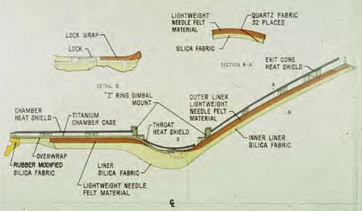
The combustion chamber consisted of an ablative-lined titanium alloy case to the 16:1 area ratio. The engine chamber and exit cone portions were machined from 6A1-4V titanium alloy forgings and welded into one unit at the throat centerline. The shell thickness was a uniform 0.035" except at the upper end where the head end bolted on, and at the lower flange where the nozzle extension attached. Flanges on either side of the throat attached to Z-shaped aluminum rings to which the gimbal trunnions were attached.
Since the titanium chamber was one piece, the ablative liner was fabricated in two sections and installed from either end. A metal fitting positively locked the liner halves together as they were installed. This lock was redundant since the nozzle extension shape was such that the ablative liner was retained in the exit cone during transportation, launch and boost. During engine firing, thrust loads forced the exit cone liner against the case. The titanium head-end assembly attached to the combustion chamber with 36 A-286 steel 0.250" bolts. This joint also transferred moments around the corner insuring a continuous pressure vessel.
In order to keep the maximum case operating temperatures around 800°F, the composite ablative liner provided the maximum heat sink at minimum weight. The selected configuration consisted of a high density, erosion-resistant silica cloth/phenolic material surrounded by a lightweight needle-felted silica mat/phenolic insulation. Temperature around the combustion chamber area was maintained below 400°F due to a heat shield attached to the case exterior. Two layers of 0.0015" stainless steel foil separated by fiberglass wool comprised the heat shield. Structurally, the ablative liner was not required to carry loads in the pressure vessel. The maximum internal pressure was 116 psi with an ultimate load factor of 3.0.
The radiation-cooled nozzle extension was attached to the combustion chamber case at the 16:1 area ratio location and extended to the exit area ratio of 47.5:1. Columbium alloy C-103 was selected as the nozzle extension material because of its high-temperature (2,700°F) structural properties. An aluminide coating provided oxidation resistance and high emissivity. The Wah Chang Company supplied the very thin columbium nozzle and coatings. The nozzle extension was reinforced with a single flat ring that helped maintain its shape. It was very thin so that if the LM landed on a boulder the nozzle would crush rather than toppling the LM. In addition to surviving the aerodynamic, firing and vibration environments of launch and boost, the nozzle extension could also collapse without upsetting the LM should it strike a lunar surface protrusion. Nozzle extension fabrication involved sheets welded in segments, stepped down in thickness towards the exit plane. At the combustion chamber attachment plane the thickness was 0.060", which provided a stiff surface for the seal between thrust chamber and nozzle extension. A 9", 0.030" thick section was attached 3" below the attachment flange. The next 13" segment was 0.020" thick and the last 15" was 0.010" thick. At the exit plane an I-shaped titanium ring provided stiffness during handling, launch and boost.
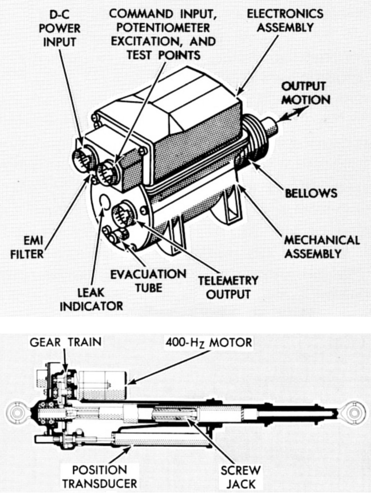
Throttle Valve Actuator
The throttle valve actuator, built by Bendix Commercial Vehicle Systems, was a linear-motion electromechanical servo actuator that moved the throttle linkage in response to an electrical command. Moving the throttle linkage simultaneously changed the flow control valve pintle positions and the injector sleeve, thereby varying the amount of fuel and oxidizer metered into the engine and changing the engine thrust. The throttle valve actuator was located between the fuel and oxidizer flow control valves with its housing rigidly attached to the engine head end and its output shaft attached to the throttle linkage.
The throttle valve actuator was controlled by three redundant electronic channels, which powered three DC torque motors. The motor shafts supplied the input to a ball screw that converted rotary motion to throttle valve actuator output shaft linear motion. All mechanical actuator moving parts were within a hermetically sealed portion of the unit, pressurized to 0.25 psia with a 9:1 nitrogen-helium mixture. A leak indicator in the cover provided visual evidence of vacuum loss within the unit. Five potentiometers were ganged to the torque motor shaft through a single-stage planetary reduction gear. Three of these potentiometers supplied position feedback information to the three motor amplifier channels, one to each channel. The other two potentiometers provide throttle actuator shaft position data for telemetry to MSFN. The redundancy within the throttle valve actuator ensured that failure of any electrical component would not cause the actuator to fail. The throttle valve actuator also provided a fail-safe system in the event selective external throttle valve actuator malfunctions occurred. If either the primary 28-volt DC power or the command voltage was lost, the throttle valve actuator caused the descent engine to thrust automatically at full throttle.
Throttle Control Linkage
 |
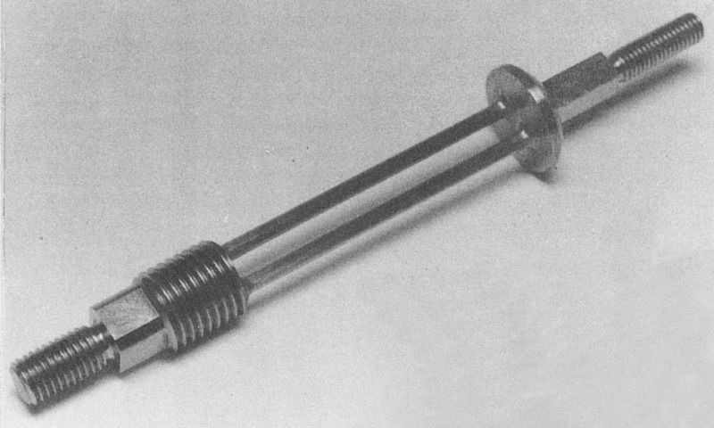 |
| Throttle Linkage Flexures | |
The linkage between the throttle actuator, the flow control valves and the variable area injector drive mechanism required high precision. The ratio between the flow control valve motion and the injector was 5:1. Total injector sleeve motion was 0.15", which means that a 10% throttle setting increment is a motion of only 0.003". In order to maintain positional coincidence between the injector sleeve and flow control valves, linkage pivot bearing looseness had to be virtually eliminated. Another design constraint was that the mechanism joints had to move in a complete vacuum. Where possible, moving elements were connected by flexures that transmitted tension and compression loads while permitting relative connected-member rotation. The flexures were designed with redundant load path that ensured against a structural failure of these critical components; either side of the flexure was capable of full load and life should one side fail. In places where a flexural element was not practical, pivot bearings were used. The first concept was to use a nonmetallic bearing fabricated of fiberglass and phenolic. Initial tests showed that the bearing wear rate and the material compliance was excessive. A simple all metal configuration using a steel bushing and a steel pin, both coated with molybdenum disulfide with an inorganic binder was substituted. This configuration also provided redundancy. The primary motion occurred between the pin and bushing inner diameter. If this assembly seized the bushing would rotate in the link mechanism bore.
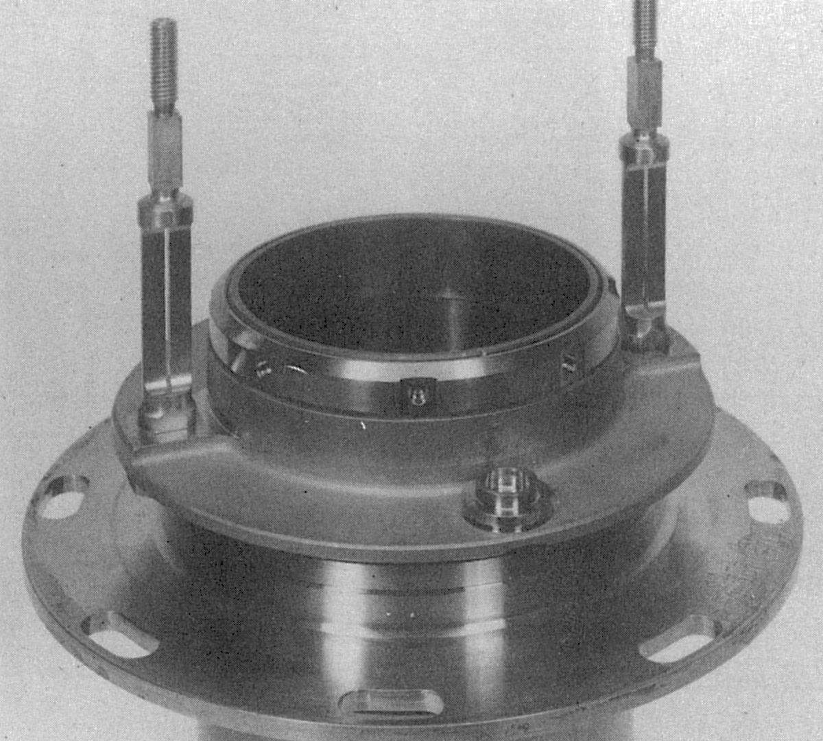
Bellows Assemblies
 |
| Two-Ply Bellows |
Both flow control valves contained moving elements that controlled propellant flow rates while containing the propellant under pressure. Bellows were used as dynamic seals, permitting direct external actuation of internal metering surfaces. A thin-wall (0.006" to 0.010") stainless steel welded bellows accomplished this. A similar bellows application was used in the injector drive. The original bellows configuration did not survive a 1963 test program to verify the bellows strength and life; fatigue cracks occurred in the single ply convolution at the weld joints. The final configuration using a two-ply design with 0.004" convolutions successfully passed all of the tests.
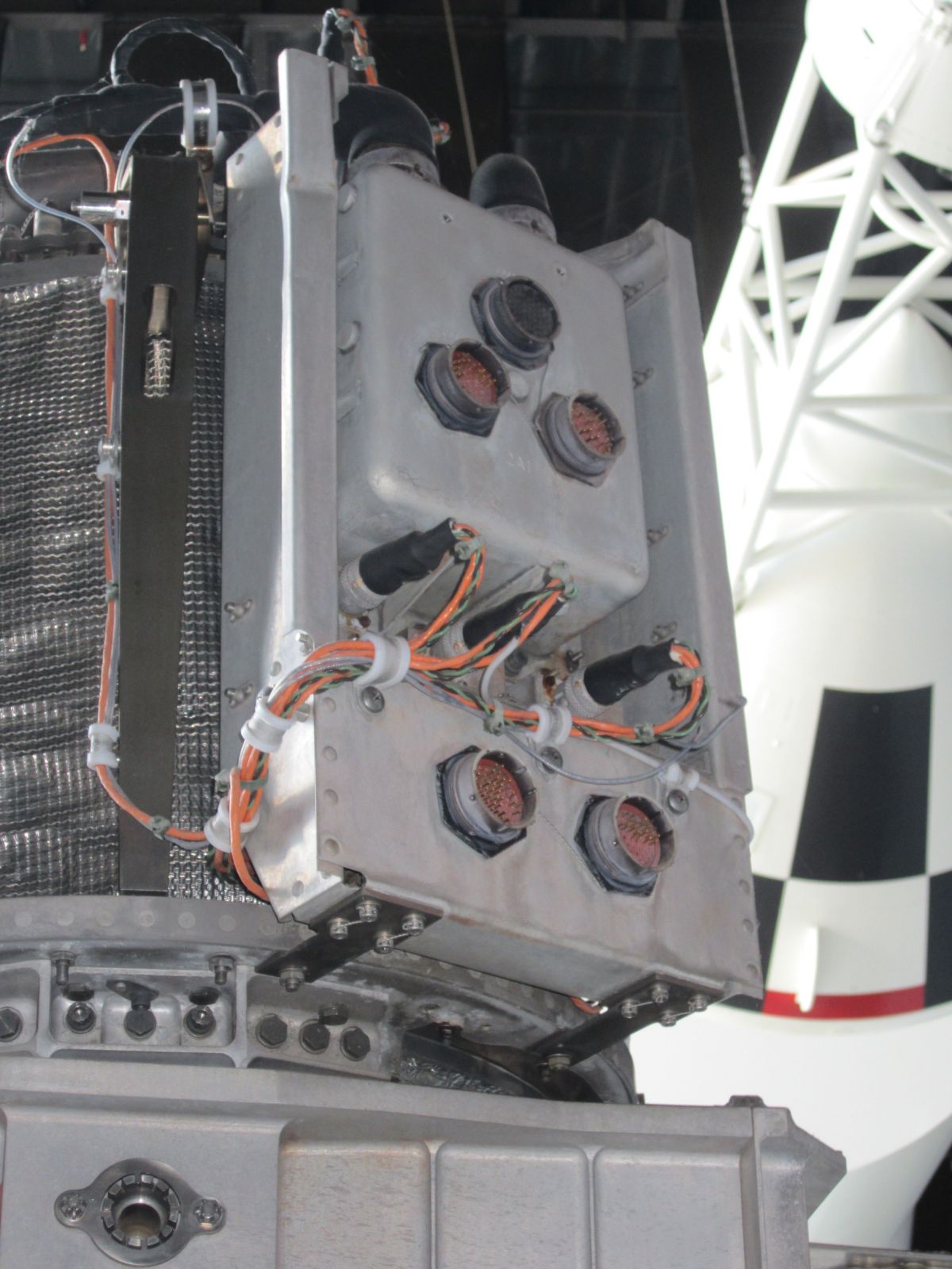
Propellant Shutoff Valve Assemblies
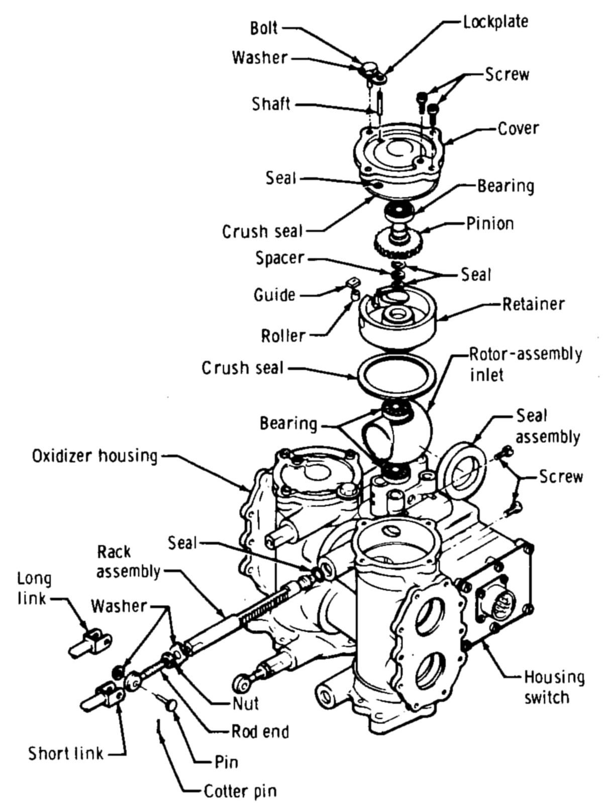 |
| Oxidizer SOV |
Each of the four propellant shutoff valve assemblies consisted of a fuel shutoff valve, an oxidizer shutoff valve, a pilot valve, and a shutoff valve actuator. The shutoff valve actuator and the fuel shutoff valve were in a common housing. The four solenoid-operated pilot valves controlled the fuel that was used as actuation fluid to open the fuel shutoff valves. The oxidizer shutoff valve was actuated by a mechanical linkage driven from the fuel shutoff valve. When the pilot valves were opened, the actuation fluid flow (at approximately 110 psia) acted against the spring-loaded actuator plunger, opening the shutoff valves. When the engine-firing signal was removed, the pilot valves closed and sealed off the actuation fluid. The propellant shutoff valves were closed by the return action of the actuator piston springs, which expelled the fuel entrapped in the cylinders and valve passages through the pilot valve vent port. The propellant shutoff valves were ball valves. The ball element operated against a spring-loaded soft seat to ensure positive sealing when the valve was closed. A piston in each shutoff valve actuator drove a rack that meshed with a pinion on the ball valve shaft.
The propellant shutoff valve actuation line branched off the main fuel line at the engine inlet and passed through the parallel-redundant actuator isolation valves to four solenoid-operated pilot valves. From the pilot valves, the fuel entered the hydraulically operated actuators, which open the propellant shutoff valves. The actuator pistons were connected to rack-and-pinion linkages that rotated the shutoff valve balls 90° to the open position. The actuator isolation valves opened when the astronauts armed the descent engine. When the engine was commanded on the four pilot valves opened simultaneously, causing actuation fuel to open the propellant ball valves, thus routing fuel and oxidizer to the combustion chamber.
Flow Control Valves
 |
| Flow Control Valve |
The oxidizer and fuel flow control valves were secured to the throttle valve actuator mounting bracket, located on the side of the engine, immediately downstream of the propellant inlet lines. The flow control valve pintle assemblies were mechanically linked to the throttle valve actuator by a crossbeam. The flow control valves were non-redundant cavitating venturis with movable pintle sleeves. Engine throttling was initiated by an electrical signal to the throttle valve actuator, commanding an increase or decrease in engine thrust. Throttle valve actuator operation changed the flow control valve pintle axial position, which decreased or increased the pintle flow areas, controlling propellant flow rate. Below an approximate 70% thrust setting, flow through the valves cavitated, and hydraulically uncoupled the propellant transfer system (and thereby, the flow rate) from variations in combustion chamber pressure. In the throttling range between 55% and 92.5% thrust, operation of the flow control valves' cavitating venturis became unpredictable and may have caused an improper fuel/oxidizer mixture ratio, which would have resulted in excessive engine throat erosion and early combustion chamber burn-through. Full Throttle Power (FTP) was about 94.2% of rated thrust (9,900 lbT), and the throttle range went from 12.2% of rated thrust to ~65% rated thrust (1,280 to 6,825 lbT). Due to severe throat erosion problems in the range between 65% and 92.5%, throttle commands above 65% were automatically commanded to FTP.
Variable-Area Injector
 |
 |
 |
| LMDE Injector | LMDE Duty Cycle | |
The variable-area injector consisted of a pintle assembly, drive assembly, and manifold assembly. The pintle assembly introduced the propellant uniformly into the combustion chamber. The drive assembly had a two-fold function: it served as an oxidizer passage into the pintle assembly, and it contained the bearing and sealing components that permitted accurate injector sleeve positioning. The injector sleeve varied the injection area so that near-optimum injector pressure drops and propellant velocities were maintained at each thrust level. The primary function of the manifold assembly was to distribute the fuel uniformly around the outer sleeve surface. Fuel entered the manifold assembly at two locations and passed through a series of distribution plates near the outer diameter.
At the manifold center, fuel passed through a series of holes before it was admitted into a narrow passage formed by the manifold body and a faceplate. The passage smoothed out gross fuel discontinuities and assisted in cooling the injector face. The fuel then passes onto the outer surface of the sleeve, past a fuel-metering lip. The fuel was injected in the form of a hollow cylinder so that it reached the impingement zone with a uniform non-atomizing circumferential velocity profile at all flow rates. The oxidizer was injected through a double-slotted sleeve so that it formed a large number of radial filaments. Each filament partially penetrated the fuel cylinder and was enfolded by fuel in such a way that little separation of oxidizer and fuel occurred. For given propellant density, overall mixture ratio, and injector geometry, there was a range of propellant injection velocity ratios that resulted in maximum mixture ratio uniformity throughout the resultant expanding propellant spray. When they occurred, the liquid-phase reactions generated gas and vapor that atomized and distributed the remaining liquid oxidizer and fuel uniformly in all directions, resulting in high combustion efficiency.
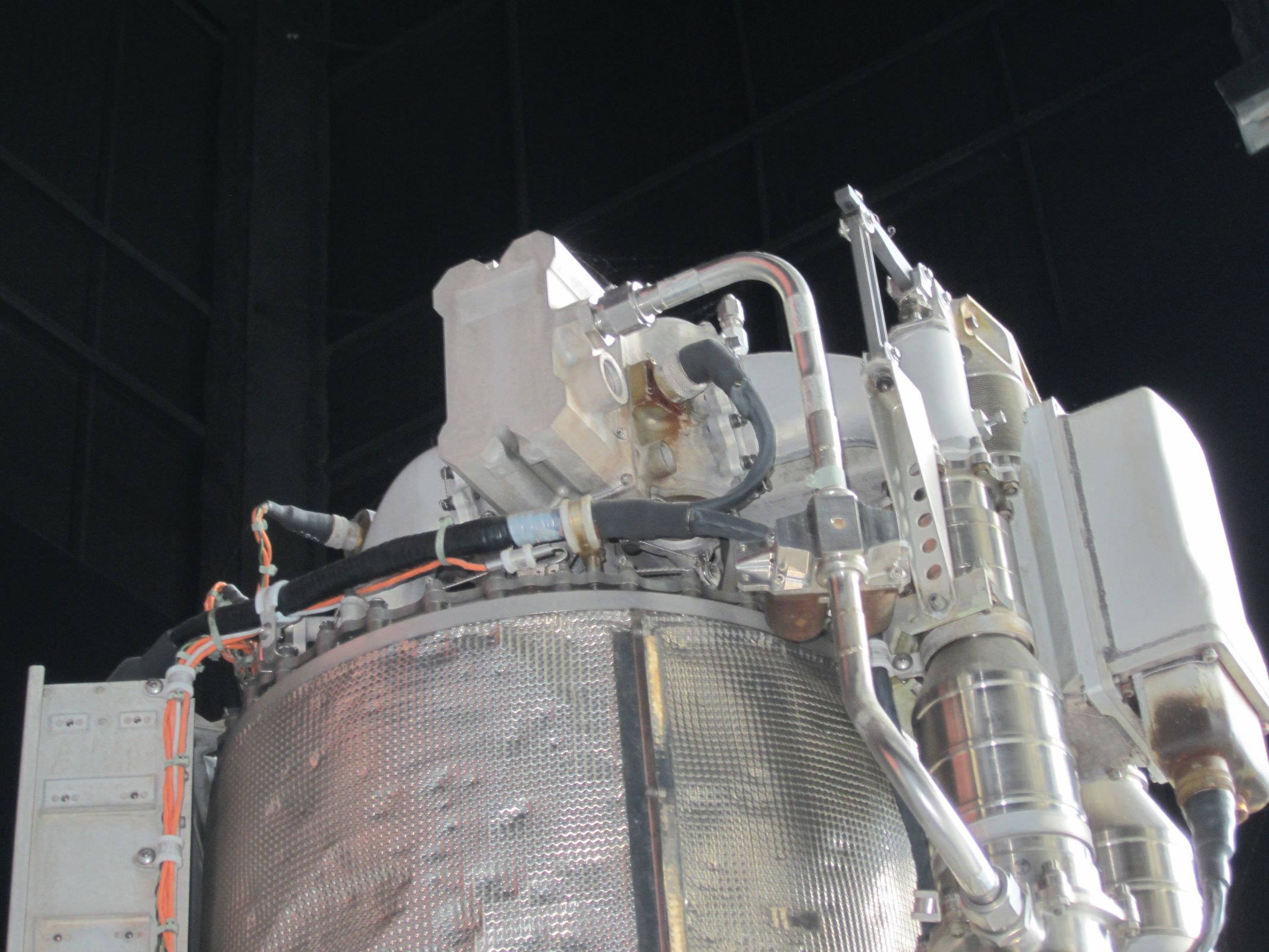
Engine Gimbal
The engine was gimbaled at the throat, not at the head end. The gimbal assembly was a rectangular frame composed of four beams with a modified I section machined from 7075-T73 aluminum alloy. The beam flanges were tapered in thickness and planform to minimize weight. A trunnion attached to the center of each beam through a spherical Fabroid bearing. One pair of trunnions mounted to the thrust chamber and the other pair mounted to the LM support truss. The gimbal drive actuators, under control of the descent engine control assembly, tilted the descent engine in the gimbal ring along the pitch and roll axes so that the engine thrust vector went through the LM center of gravity. One actuator controlled the pitch gimbal; the other, the roll gimbal. The gimbal drive actuators, built by Airesearch Mfg. Company of Los Angeles, California, consisted of a single-phase motor, a feedback potentiometer, and associated mechanical devices. They extended or retracted 2" from the center position to tilt the descent engine ± 6° along the Y-axis and Z-axis.
Engine Testing
TRW developed the LMDE on an extremely compressed schedule. Fortunately, there was plenty of hardware and a test-as-you-go philosophy that helped identify component problems early, before they could impact subassemblies and assemblies. Testing, of course, continued at the subassembly and assembly level.
One test program step involved the head end injector manifold, injector drive, ducting, shutoff valves, flow control valves, throttle actuator, and throttle linkage. This was subjected to the complete vibration environment qualification. To establish the strength margin built into the head end assembly, after qualification tests, it was tested at 125%, 150% and finally at 175% of qualification level before failure.
Combustion stability was assessed with 31 bomb tests using 5- to 50-grain charges that induced spikes up to 175% of rated chamber pressure. Elverum stated "The engine was bombed at 10%, 25%, 50% and 100% thrust. Recovery was always less than ten milliseconds. We would give it a spike, and it would damp out immediately Throughout development and flight, the LMDE never exhibited combustion instability."
Elverum believed the secret to the TRW LMDE success was that plenty of hardware was always available, which led to a philosophy of "let's just build one engine, and somehow, we'll solve all the problems as we go."
| New Builds | Starts | Firing Duration (sec) | |
|---|---|---|---|
| Injector Tests | 1,800 | 70,374 | |
| Throttling Head End Assemblies on Water-Cooled Combustion Chambers |
|||
| 28 | 941 | 61,666 | |
| Ablative Engines | |||
| Sea Level (ε = 2:1) | 21 | 67 | 5,368 |
| High Altitude (ε = 47.5:1) | 35 | 242 | 26,549 |
| Total Test Experience | 3,050 | 163,957 | |
Development
Throttling
Two different throttling concepts were explored during engine design definition and development. One used a fixed-area injector with helium injection at reduced thrust to maintain adequate combustion efficiency; propellant-flow variation was controlled by non-cavitating throttling valves that used system fuel pressures to actuate hydraulic servo-control valves. The other concept used a variable-area injector combined with cavitating-venturi propellant-flow-control valves. This injector used a coaxial center element design. A single movable sleeve modulated injector fuel and oxidizer flow areas. This injector sleeve was linked mechanically to the two cavitating flow control valves and the electrically-driven throttle-actuator assembly.
After 18 months of parallel engine development by two different contractors the variable-area-injector throttling concept was selected in January 1965. Investigators found that the fixed-area injector with helium injection experienced significant combustion instability and lower reduced-thrust performance than the variable-area injector. Maximum thrust occurred at a fixed throttle point (FTP) calibrated for optimum-mixture ratio and injector pressure difference. The FTP was optimized at 92.5% of the 10,500-lb maximum rated thrust. The design initially attempted to provide variable thrust near the maximum rated thrust but trouble with mixture-ratio control and throat erosion led to selection of an FTP maximum-thrust setting still compatible with mission requirements. Thrust between 65% and 92.5% was considered a non-operating region, although the engine could be physically throttled to any point in that region. The minimum-throttle point was 10% of rated thrust.
The helium-injection throttling studies using a fixed-area injector started in February 1963. For the first 6 months, the developmental test program was paced by the limited availability of injectors. Injector weld problems caused inter-propellant leaks that resulted in catastrophic injector failures and led to a major injector redesign to allow easier fabrication and better inspection. Combustion instability problems also plagued the early injector developmental tests. A self-induced instability, predominantly first-tangential high-frequency mode resonance was addressed by a Y-baffle on the injector face that damped the instabilities. Although this fixed the high-frequency self-induced and bomb-induced instabilities, a low-frequency buzz (200 - 590 Hz) and intermittent popping remained. Severe baffle erosion and ablative chamber undercutting near the baffles resulted during the buzz instabilities. The buzz instability was a mainly a problem at reduced throttle, and it was present with and without helium injection. Other problems included performance degradation as the engine was throttled and excessive ablative chamber-throat erosion at midrange thrust. These issues terminated the pursuit of throttling by helium injection.
Variable-area-injector throttling began in July 1963, followed by developmental hardware testing in January 1964. No major combustion-stability problems were encountered with this injector configuration. The lack of stability problems was attributed to the inherently stable design of the center-element injector, which minimized energy release near the chamber walls where most high-frequency instability modes were sustained. However, combustion roughness was experienced, which was a random pressure oscillation with no cyclic resonant frequency. The combustion roughness appeared to be caused by coarse injector design with relatively few oxidizer streams (36 primary and 36 secondary) giving rise to uneven combustion. Bomb tests were performed at various positions in the chamber, and no incidence of combustion instability occurred. The bomb tests were performed in a steel-wall combustion chamber to minimize the natural damping effect of the ablative chamber.
Ablative chamber throat erosion was significantly higher than that usually associated with fixed-thrust engines. The greatest rate of erosion occurred at full thrust. Some occurrences of excessive heating and case bulging at the throat section were observed during heat soakback following a long (approximately 400 seconds) full-thrust burn. This effect occurred after engine shutdown and was not indicative of a potential burn through.
In January 1965, NASA and TRW decided to continue the variable-area-injector engine development and to terminate the helium-injection engine. The variable-area-injector engine was selected because of better combustion stability and better combustion performance throughout the thrust range. Managers anticipated fewer development problems although the increased mechanical complexity gave the engine a lower reliability than the fixed-area-injector engine.
Since the engine qualification configuration had to be selected before all developmental problems were completely resolved, engine qualification was conducted in two phases. The phase-A qualification was conducted simultaneously with continued engine development to meet the early delivery requirements for the vehicle engine. The phase-B engine qualification was initiated in January 1967 and was completed in August 1967.
The original injector pintle tip was made of stainless steel, and incurred severe erosion during engine operation because of inadequate cooling. As a result of the erosion, copper slugs were incorporated in the pintle tip to improve heat transfer. This configuration was used in the first engine qualification design (phase A). The phase-B qualification engine used a columbium-alloy pintle tip was used because the copper-slug had not completely eliminated the erosion. No erosion occurred with the columbium tip. The phase-A injector exhibited very uneven throat-erosion patterns with severe gouging in some areas. This gouging was caused by poor injector-inlet hydraulics on the oxidizer side. A small step acting as a turbulator was added to the phase-B injector oxidizer inlet tube to provide an even velocity distribution in the oxidizer fans. As a result of this addition, uneven throat erosion was greatly reduced and gouging eliminated.
The phase-A engine ablative thrust chamber had a slotted turbulence ring approximately 5" downstream from the injector face. The turbulence ring was eliminated on the phase-B engine to allow the fuel-barrier coolant flow to extend farther down the chamber wall, reducing throat erosion. During phase-B qualification testing, gouging did occur on one engine and was traced to a fuel-barrier cooling orifice being plugged by room temperature vulcanized (RTV) rubber, which was used as a seal around the cooling orifice tubes at the ablative faceplate. A process change was made to prevent fuel-barrier cooling orifice plugging during assembly. Another phase-B qualification test engine incurred a failure of the electron-beam (EB) weld on the guide bar that positions the oxidizer sealing ring. This failure also occurred on several White Sands Test Facility (WSTF) engines, and in some cases, the guide bar came completely out from under the oxidizer sleeve. Subsequently, an EB tack weld in the guide bar center was changed to a structural EB weld around the guide bar periphery.
During WSTF systems tests, several engines exhibited 500-Hz pressure oscillations in the oxidizer-injector manifold at about 40% thrust. The worst oscillations were as high as 300 psi peak-to-peak. Initially, the oscillations could not be duplicated on TRW engine-test stands. An investigation comparing the WSTF and TRW facilities revealed that a flow-control valve oscillation was being amplified by a pressure transducer line peculiar to the WSTF test rig.
Several engines exhibited resonant 100-Hz, 10 psi peak-to-peak, chamber pressure oscillations at about 25% thrust. These oscillations were found to be damped by propellant helium saturation. Previous engine testing had been done without helium-saturated propellants. Helium saturation was representative of the propellant flight conditions.
Shutoff Valve
During the engine shutoff valve (SOV) development and qualification, several minor problems occurred. A chronic problem was SOV rotor-seal leakage. Generally, the seals met the 10-scc/hr gaseous nitrogen leakage requirement, but they were sensitive to contamination and scoring. The leakage was caused by rotor cycling in the dry condition and long-term propellant exposure, which generated residue contaminants. Dry cycles before launch was limited to 250 and precautions reduced the valve-actuation time during dry cycling to approximately 2 to 3 seconds, thereby preventing seal damage by very rapid actuation. Contamination leakage was corrected by replacing leaky seals before engine delivery.
Developmental and WSTF engines encountered several instances of rack jamming or sluggish valve actuation during test. This was caused by oxidizer leakage past the shaft seals into the gear cavities and subsequent oxidizer reaction with the gear lubricant. No valves completely jammed, but all shaft seal leakage cases resulted in sluggish valve actuation on the affected rack. The gear cavities on all flight engines were checked for leaks and acidity before delivery. Also, an actuation force check to detect sluggish valves was performed at the contractor's plant and at the NASA KSC to measure the cracking and full-open actuation force on the four actuators. Each actuator's valve position was indicated by reed switches. During development and qualification, the switches were unreliable and gave false indications, the cause of which was not fully understood. It was thought that the engine vibration environment interacted with the delicately-constructed reed switches. After the flight of LM-1, on which a false indication was noted, engineers reevaluated the need for valve-position indication. Because no mission decision required valve position indication, and because the reed switches were unreliable, they were eliminated, saving about 1.5 lb.
Flow Control Valve Elbows
The original flow control valve (FCV) elbow was made of stamped 6061 aluminum sheet and machined 6061 aluminum flanges, all welded together. Cracks occurred in a weld near the flange during qualification tests and were caused by the closeness of the weld to the flange, which resulted in a stress concentration. As designed, the weld was very difficult to inspect so the elbow was redesigned to relocate the weld farther from the flange to improve the strength and inspection access. The redesigned elbow passed qualification; however, during production of elbows for flight engines, several elbows cracked during the proof-pressure test (540 psig). These cracks occurred in a weld adjacent to the throttle-linkage boss. An X-ray of the weld in this area showed that some elbows had a void in the weld caused by inadequate penetration from the welds made on the inner and outer surfaces of the elbow. Subsequently, all elbows were inspected by X-ray for weld voids, a process that resulted in a high scrap rate. A new two-piece elbow was designed and qualified for use in later flight engines. The new elbow consisted of two pieces machined from solid 6061 aluminum and joined by a single, easily inspected weld. During phase-B engine production, an FCV retaining nut was found to have a fatigue crack in a thread root, caused during FCV water-flow calibration. At certain thrust levels (about 10%), the water flow produced excessive pressure oscillations in the cavitating venturi, resulting in retaining nut fatigue. This phenomenon appeared during flow tests both with water and flight propellants. Because the retaining nuts on all flight engines were susceptible to the problem, corrective action had to be taken. Therefore, all engines were modified by applying epoxy beneath the retaining nut, thus bonding it in place even if it cracked completely through.
Engine chamber and injector pressure transducer calibration shifted after exposure to propellant and atmospheric environment during development and qualification testing. Residual propellant and moisture reacted to form acid that etched transducer diaphragms. The problem was avoided by installing flight-engine pressure transducers after acceptance firing and after cleaning the engine for delivery.
References
Apollo Operations Handbook, Block II Spacecraft, Volume 1: Spacecraft Description 5M2A-03-BLOCK II (Houston, Texas: Manned Spacecraft Center, 15 Oct 1969).
Brooks, Courtney G., James M. Grimwood, Loyd S. Swenson, Jr. Chariots for Apollo: A History of Manned Lunar Spacecraft NASA SP-4205 (Washington, DC: NASA, 1979).
Cherne, Jack M. Mechanical Design of the Lunar Module Descent Engine (Redondo Beach, California: TRW Systems, 1967).
Dressler, Gordon A., J. Martin Bauer TRW Pintle Engine Heritage and Performance Characteristics (Redondo Beach, California: TRW Inc., 2000
Fisher, Steven C. and Shamin A. Rahman, eds. Remembering the Giants: Apollo Rocket Propulsion Development (Washington, DC: NASA, 2009).
Hoagland, Richard. Apollo News Reference (Bethpage, New York: Public Affairs, Space, Grumman Aerospace Corporation, 1971).
Humphries, Clarence E. and Reuben E. Taylor Apollo Experience Report — Ascent Propulsion System TN D-7082 (Houston, Texas: NASA Manned Spacecraft Center Mar 1973).
Hammock Jr., William R., Eldon C. Currie and and Arlie E. Fisher. Apollo Experience Report — Descent Propulsion System TN D-7143 (Houston, Texas: NASA Manned Spacecraft Center, Mar 1973).
Interbartolo, Michael Apollo Lunar Module Propulsion Systems Overview JSC-17237-14 (Houston, Texas: NASA Johnson Space Center, 1 Jan 2009).
Lunar Module LM-10 through LM-14 Vehicle Familiarization Manual LMA790-2 (Bethpage, New York: Grumman, 1 Nov 1969).
Vaughan, Chester A., Robert Villemarette, Witalij Karakulko, Donald R. Blevins Apollo Experience Report — Lunar Module Reaction Control System TN D-6740 (Houston, Texas: Manned Spacecraft Center, Mar 1972).
--- On to Part 9.43, The Apollo Lunar Module Ascent Propulsion System ---
Send mail to
![]() with questions or comments about this web site.
with questions or comments about this web site.
![]()