
The SM Reaction Control System (RCS)
|
|
| Quad Placement | Orientation |
The reaction control subsystem (RCS) provided thrust for normal and emergency Apollo spacecraft attitude maneuvers. Subsystem operation was in response to automatic control signals from the stabilization and control subsystem in conjunction with the guidance and navigation subsystem. The RCS could be controlled manually by the crew. The RCS consisted of CM and SM reaction control systems. The SM RCS is discussed here while the CM RCS is discussed in an earlier article.
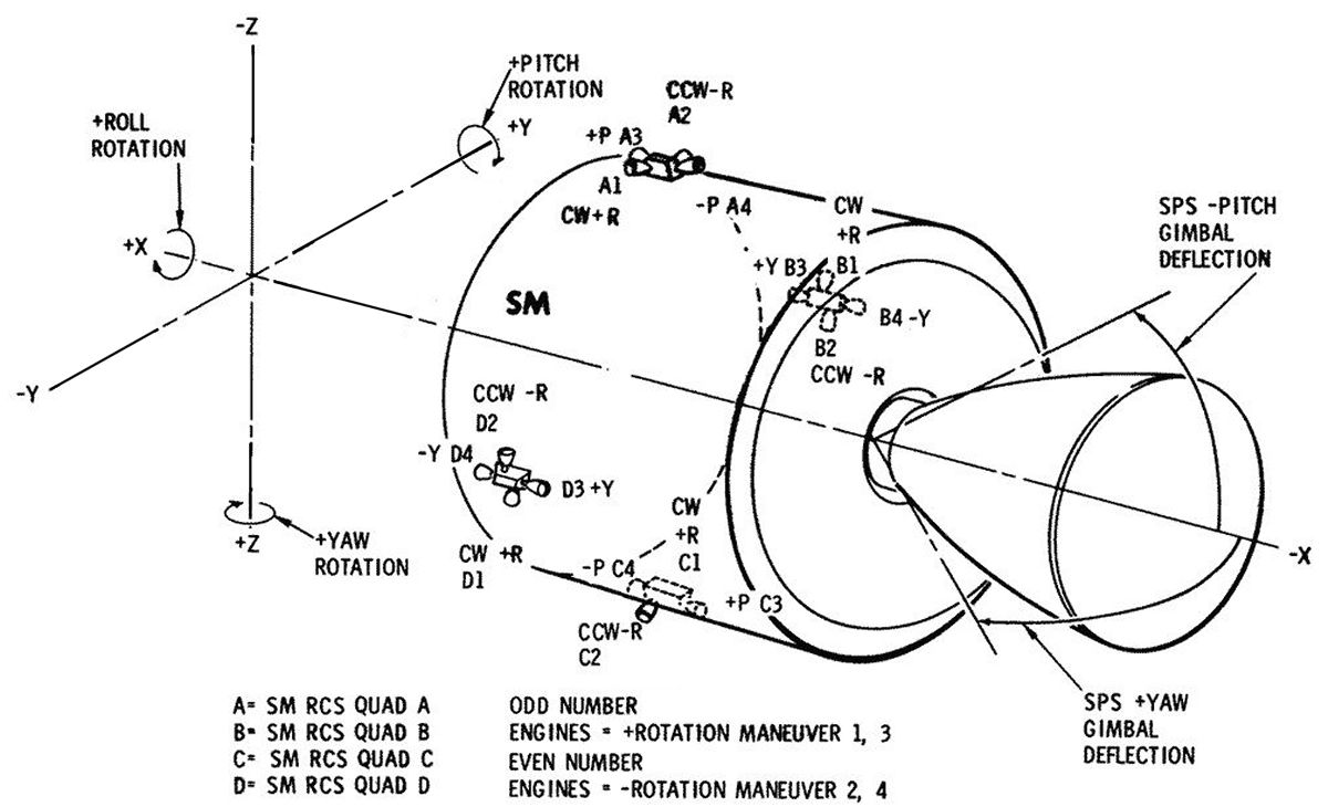
The SM RCS consisted of four similar, independent systems (quads) located 90° apart around the service module. Each quad had four rocket engines that provided thrust for three-axis spacecraft stabilization and control during earth orbit, translunar trajectory abort, transposition and docking, along with translunar, lunar orbital, and transearth flight. It also was used for minor course corrections both on the translunar and transearth flights.
The system provided small velocity changes required for service propulsion subsystem propellant settling (ullage) maneuvers. Only roll axis control was provided during service propulsion engine thrusting. In addition, the RCS provided velocity changes for spacecraft/third stage separation during high-altitude or translunar injection abort, for separation from the boost vehicle after spacecraft injection into translunar trajectory, LM rendezvous in lunar orbit, and for CM-SM separation.
The four quads could be operated simultaneously or in pairs during spacecraft maneuvers. Each quad was mounted on a honeycomb structural panel about 8 feet long and 3 feet wide. It became part of the integrated service module structure when hinged and bolted in place. Engine mount center lines were offset about 7° from the Y and Z axes. Each quad cluster was rigidly mounted in a housing on the honeycomb panel exterior. Laterally mounted (roll) engines were used for rotating the vehicle about the X axis. Longitudinally mounted engines were used for rotating the vehicle about the Y and Z axes and translational maneuvers along the X axis. Roll engines were offset to minimize engine housing frontal area, which reduced boost heating effects. All engines in quad were canted 10° outward to reduce the effects of exhaust plume impingement on the service module structure.
Each engine provided approximately 100 lbT and used hypergolic propellants. The fuel was monomethyl hydrazine (MMH) and the oxidizer was nitrogen tetroxide (N2O4). The engines were produced by The Marquardt Corporation of Van Nuys, California. Reaction control engines could be pulse-fired (in bursts) to produce short-thrust impulses or fired continuously to produce a steady thrust. The short pulse firing was used for attitude-hold and navigation alignment maneuvers. Attitude control was maintained with two adjacent quads operating. Each quad contained a pressure-fed, positive expulsion propellant feed system. The propellant tanks (two fuel and two oxidizer) were located on the structural panel interior; engine feed lines were routed through the panel. The propellant tanks were produced by Bell Aerosystems Company of Buffalo, New York, a division of Textron, Inc.
SM RCS Components
The following describes components comprising each quad.
A spherical titanium helium tank, manufactured by the Airite Division of Sargent Industries, El Segundo, California, weighed 11.5 lb, had a 12.37" outside diameter, a 0.135" wall thickness, a 910 in³ internal volume, was pressurized to 4,150 psig, and held 1.35 lb of helium.
The cylindrical titanium fuel and oxidizer tanks had domed ends and were manufactured by Bell Aerosystems Company of Buffalo, New York. The primary fuel tank had a 23.717" length, a 12.62" outside diameter, a 0.017" to 0.022" wall thickness and an ullage volume of 69.1 lb, resulting in tank pressure no greater than 215 psia at 85°F. The primary oxidizer tank had a 28.558" length, a 12.62" outside diameter, a 0.017" to 0.022"wall thickness, and a 137 lb ullage volume, resulting in tank pressure no greater than 215 psia at 85°F. The secondary fuel tank had a 17.329" length, a 12.65" outside diameter, a 0.022" to 0.027" wall thickness, and a 45.2 lb ullage volume that resulted in tank pressure no greater than 205 psia at 105°F. The secondary oxidizer tank had a 19.907" length, a 12.65" outside diameter, a 0.022" to 0.027" wall thickness, and a 89.2 lb ullage volume that resulted in tank pressure no greater than 205 psig at 105°F.
Four Marquardt R-4D reaction control rocket engines were clustered on the quad exterior. They were the only nonablative engines on the command and service module. The thrust chambers were pure molybdenum, and nozzle extensions were a cobalt-base alloy. Each engine had a 100 lbT nominal thrust, a 1,000 second service life, was capable of 10,000 operation cycle, was 13.4" long, weighed 5 lb, and had a 5.6". nozzle exit diameter.
 |
 |
 |
| RCS Quad Exterior | RCS Quad Interior | RCS Quad Components |
SM RCS Operation
 |
 |
| RCS Quad Functional FLow | RCS Electrical Control |
Each quad contained pressurization, propellant, rocket engine, and temperature control subsystems.
The pressurization system regulated and distributed helium to the propellant tanks. It consists of a helium storage tank, isolation valves, pressure regulators, check valves, relief valves, and lines necessary for filling, draining, and distribution of the helium. Isolation valves between the helium tank and pressure regulators contained two solenoids — one was energized momentarily to latch the valve open magnetically while the other was energized momentarily to unlatch the valve; spring pressure and helium pressure forced the valve closed. The isolation valves in each quad were individually controlled by switches on the CM main display console. The valves were normally open to pressurize the system. They were held open by a magnetic latch rather than by the application of power, which conserved power and prevented valve coil overheating. Helium pressure was regulated by two assemblies connected in parallel, with one assembly downstream of each isolation valve. Each assembly incorporated two (primary and secondary) regulators connected in series. The secondary regulator remained open if the primary regulator functioned properly. If the primary regulator failed open, the secondary regulator maintained slightly higher but acceptable pressure. Two check valve assemblies, one for oxidizer and one for fuel, permitted helium flow to the tanks and prevented propellant or propellant vapor flow into the pressurization system if seepage or failure occurred in the propellant tank bladders. Filters were incorporated in the inlet to each check valve assembly and each test port The helium relief valve contained a diaphragm, filter, a bleed device, and the relief valve. The diaphragm was installed to provide a more positive seal against helium than that of the actual relief valve. The diaphragm ruptured at 228 psia. The filter retained any fragments from the diaphragm and prevented particles from flowing onto the relief valve seat. The relief valve opened at 236 psia and dumped excessive pressure overboard. The relief valve reseated at 220 psia. A pressure bleed device vented the cavity between the diaphragm and relief valve if there was leakage across the diaphragm, or upon completion of relief valve checkout. The bleed device was normally open but closed fully when the pressure increased to 150 psia; it was be fully opened when the pressure decreased to 20 psia.
The propellant system consisted of two oxidizer tanks, two fuel tanks, two oxidizer and two fuel isolation valves, a fuel and oxidizer inline filter, and associated distribution plumbing. Oxidizer supply tanks were mounted to SM structural panels. Each tank contained a diffuser tube assembly and a Teflon bladder for positive oxidizer expulsion. The bladder was attached to the diffuser tube at each end of each tank. The diffuser tube acted as the propellant outlet. When the tanks were pressurized, helium surrounded the entire bladder, exerting a force that caused the bladder to collapse about the oxidizer, forcing it into the diffuser tube assembly, out the tank outlet and into the manifold, thus providing expulsion during zero gravity. Fuel supply tanks were also mounted to SM structural panels. They were similar in material, construction, operation, and diameter to oxidizer tanks.
Isolation valves in each quad's fuel and oxidizer tank lines were controlled by switches on the CM main display console. Each isolation valve contained solenoids and indicators that operated in the same manner as the helium isolation valves. The primary tank valves were normally open and the secondary valves normally closed. When a propellant quantity indicator displayed 43% propellant remaining, the secondary valves opened and the primary valves closed. The valves may be closed to prevent fluid flow in the event of a failure such as line rupture or a runaway thruster. Propellant distribution plumbing was identical in each quad. Filters in the fuel and oxidizer lines between the propellant isolation valves and engine manifold prevented particles from flowing into the engine injector valves and engine injector.
 |
 |
| Engine Exterior | Cross Section |
The SM reaction control engines were 100 lbT radiation cooled, pressure fed, bipropellant thrust generators that could be operated in either the pulse or steady-state mode. Each engine consisted of a fuel and oxidizer injector control valve that controlled propellant flow in response to automatic or manual electrical commands, and an injector head assembly that directed propellant flow from each control valve to the combustion chamber. Each fuel and oxidizer solenoid injector valve had an inlet filter. An orifice in the inlet of each fuel and oxidizer solenoid injector valve metered the propellant flow to obtain a nominal 2:1 oxidizer-fuel ratio.
The propellant solenoid injector valves used two coaxially wound coils, one for automatic and one for direct manual operation. The automatic coil was used when the thrust command originated from the controller reaction jet assembly, which was the electronic circuitry that selected the required automatic coils to be energized for a given maneuver. The direct manual coils were used when the thrust command originated at the rotation control, direct ullage pushbutton, service propulsion subsystem abort, or the SM jettison controller.
The main chamber injector caused eight fuel streams to impinge upon eight oxidizer streams for main chamber ignition. There were also eight fuel holes around the outer injector periphery to provide combustion chamber wall film cooling. The injector featured a precombustion chamber where single fuel and oxidizer streams impinged upon each other, providing a smoother start transient. The combustion chamber was constructed of unalloyed molybdenum coated with molybdenum disilicide to prevent oxidation of the base metal. The nozzle extension with integral stiffener rings was machined from a cobalt base alloy.
Each of the engine mounts contained two electrical strip heaters, each with two elements. One element in each heater was controlled by a secondary temperature therm-o-switch that was set to open at 118°F and close at 70°F. When a switch on the main display console for that quad was set for the secondary system, DC power was supplied to the therm-o-switch in each heater of that quad and automatically opened and closed according to the temperature. When the switch was set for the primary heater, power was supplied to the redundant element in each quad's heater. This therm-o-switch was a higher temperature switch that automatically opened at 134°F and closed at 115°F. The heaters provided propellant temperature control by conductance to the engine housing and engine injector valves. A gauge on the main display console was used to monitor the package temperature of any one of the four SM quads,
Each quad's helium tank pressure and temperature was monitored by a pressure/ temperature ratio transducer. This provides a signal to a switch on the CM main display console. When the switch was positioned to a given quad, the pressure/temperature ratio signal was transmitted to a propellant quantity gauge, and the propellant quantity remaining for that quad was indicated in percent.
--- On to Part 9.40, The Apollo Lunar Module ---
Send mail to
![]() with questions or comments about this web site.
with questions or comments about this web site.
![]()