U.S. Manned Rocket Propulsion Evolution
Part 9.46: Apollo Lunar Module Guidance, Navigation and Control
Compiled by Kimble D. McCutcheon
Published 9 Dec 2022; Revised 8 Jan 2023

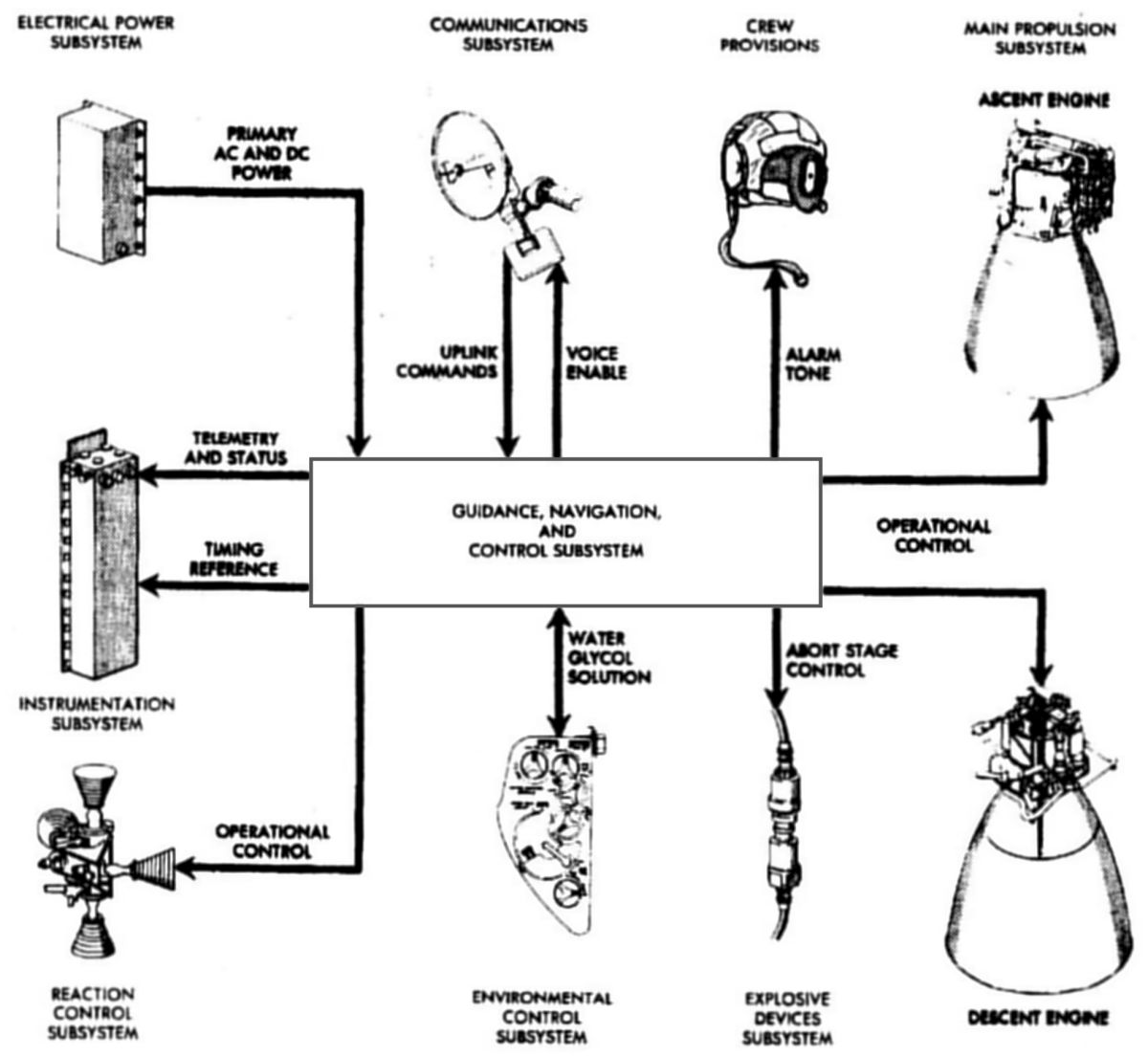
Lunar Module GNCS Subsystems |
Compared to lunar module guidance, navigation and control, command GN&C was a walk in the park. LM control involved numerous additional considerations, including:
- Shifting center of gravity
- Two (descent, ascent) configurations, each with a different moment of inertia
- A throttable descent engine
- A non-gimbaled ascent engine
- Landing and rendezvous ranging radar inputs
- Speed ranges from lunar orbital speed to zero and zero to lunar orbital speed
The LM took two astronauts from the orbiting CSM to the lunar surface and back again. LM guidance, navigation and control made this possible.
|
1.0 Overview
 |
 |
 |
 |
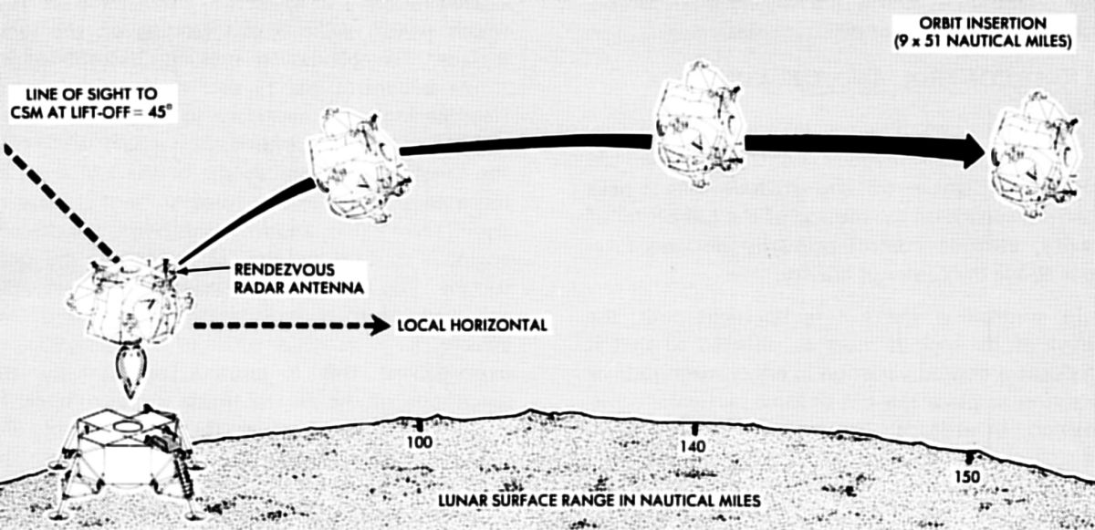
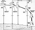
| Lunar Module Descent and Ascent Profiles |
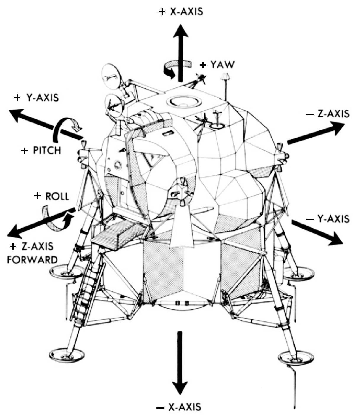
LM Axes |
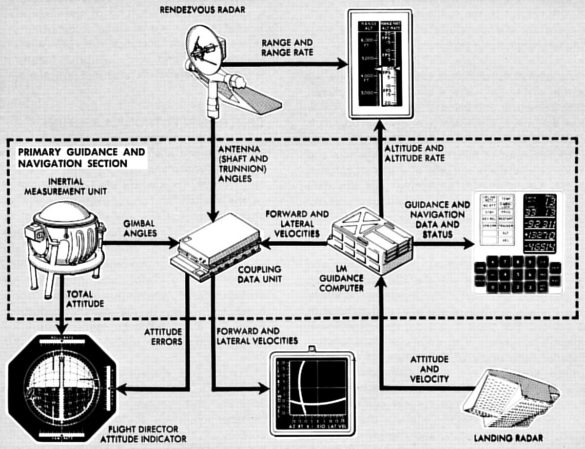
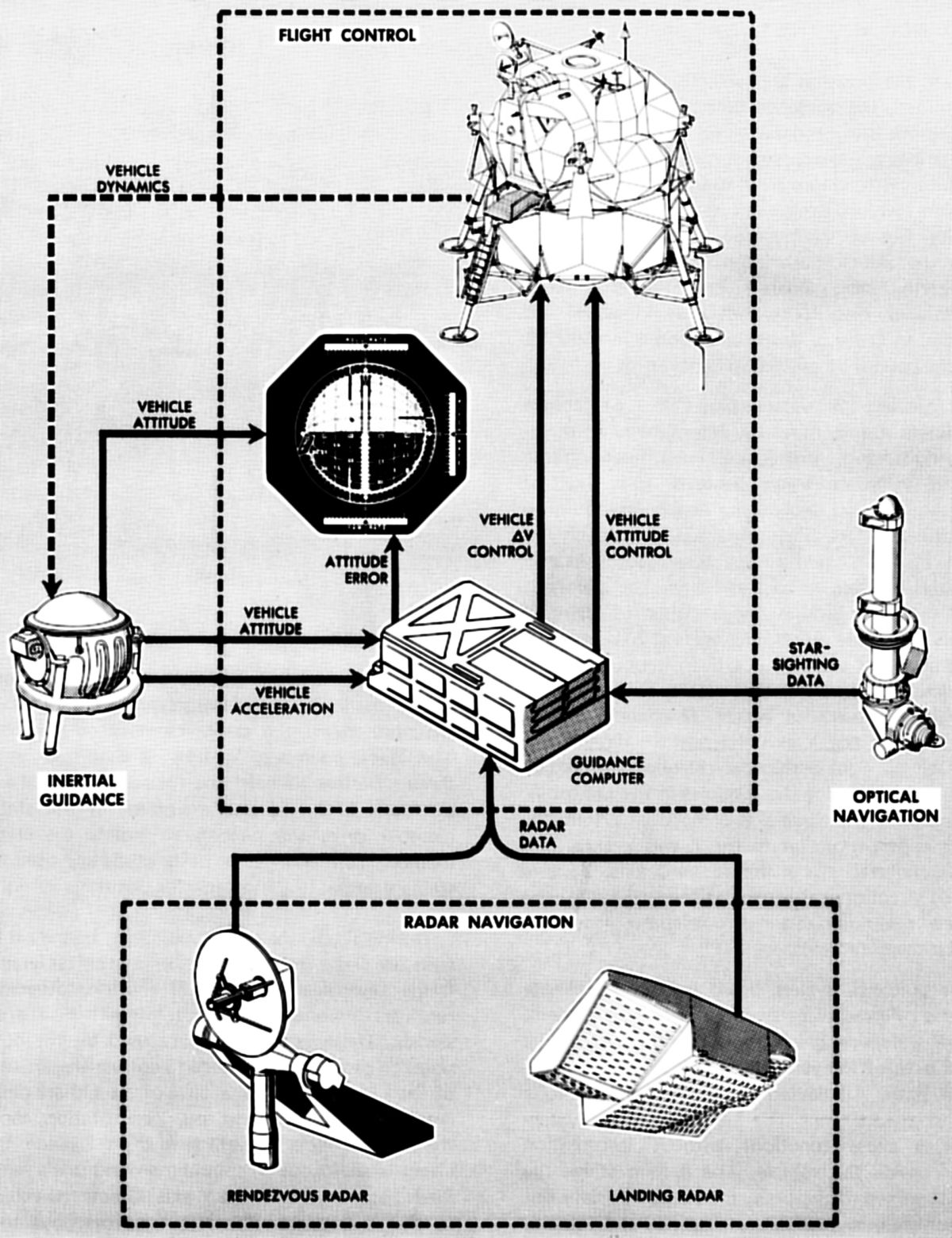
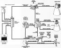
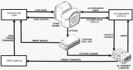
The LM Guidance, Navigation, and Control Subsystem (GNCS) accumulated, analyzed, and processed data to ensure that the LM followed a predetermined flight plan. The GNCS provided navigation, guidance, and flight control to accomplish mission objectives. Functionally, this equipment was contained in a primary guidance and navigation section (PGNS), an abort guidance section (AGS), and a control electronics section (CES). The PGNS used inertial guidance and optical navigation for the LM. When aided by either the rendezvous radar (RR) or the landing radar (LR), the PGNS provided radar navigation. When used in conjunction with the CES, the PGNS provided automatic flight control. The astronauts could supplement or override automatic control with manual inputs.
The PGNS acted as a digital autopilot, controlling the LM throughout the mission. Normal guidance requirements included transferring the LM from a lunar orbit to its descent profile, achieving a successful landing at a pre-selected or crew-selected site, and performing a powered ascent that resulted in CSM rendezvous. The PGNS provided the navigational data for LM guidance, which included line-of-sight (LOS) data from an alignment optical telescope (AOT), for inertial reference unit alignment, signals for initializing and aligning the AGS, and data to the astronauts for determining the computed landing site location.
The AGS was primarily used if the PGNS malfunctioned. When the PGNS was functioning properly and a mission was aborted, it was used to control the LM. If the PGNS failed, the lunar mission was aborted, thus the term "abort guidance section." Abort guidance only provided guidance to place the LM in a rendezvous trajectory with the CSM or in a parking orbit for CSM-active rendezvous. The PGNS performed the navigation function, but navigation information was also supplied to the AGS. In case of a PGNS malfunction, the AGS used the last navigation data provided. The astronaut could update the navigation data by manually inserting RR data into the AGS.
When the AGS was used as PGNS backup during a mission abort, it determined the LM trajectory or trajectories required for CSM rendezvous and could guide the LM from any point in the mission, from separation to rendezvous and docking, including ascent from the lunar surface. It could provide data for attitude displays, make explicit guidance computations, and issue commands for firing and shutting down the engines. Guidance could be accomplished automatically, or manually by the astronauts, based on data from the AGS. When the AGS was used in conjunction with the CES, it functioned as an analog autopilot. The AGS was an inertial system rigidly strapped to the LM rather than mounted on a gimbaled stabilized platform. It offered sufficient accuracy for lunar missions, with savings in size and weight. It could also be updated manually with radar and optical aids.
The CES processed Reaction Control Subsystem (RCS) and Main Propulsion Subsystem (MPS) control signals for LM stabilization and control. To stabilize the LM during all mission phases, the CES provided signals that fired any combination of 16 RCS thrusters. These signals controlled attitude and translation about or along all axes. The attitude and translation control data inputs originated from the PGNS during normal automatic operation, from hand controllers during manual operations, or from the AGS during certain abort situations. The CES also processed on/off commands for the ascent and descent engines and routed automatic and manual throttle commands to the descent engine. The descent engine gimbal had trim control to align its thrust vector with the LM center of gravity (CG). The integrated PGNS, AGS, and CES sections allowed astronauts to operate the LM in fully automatic, several semiautomatic, and manual control modes.
2.0 Primary Guidance and Navigation Section
 |
 |
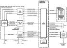
| LM PGNS |
LM PGNS Displays |
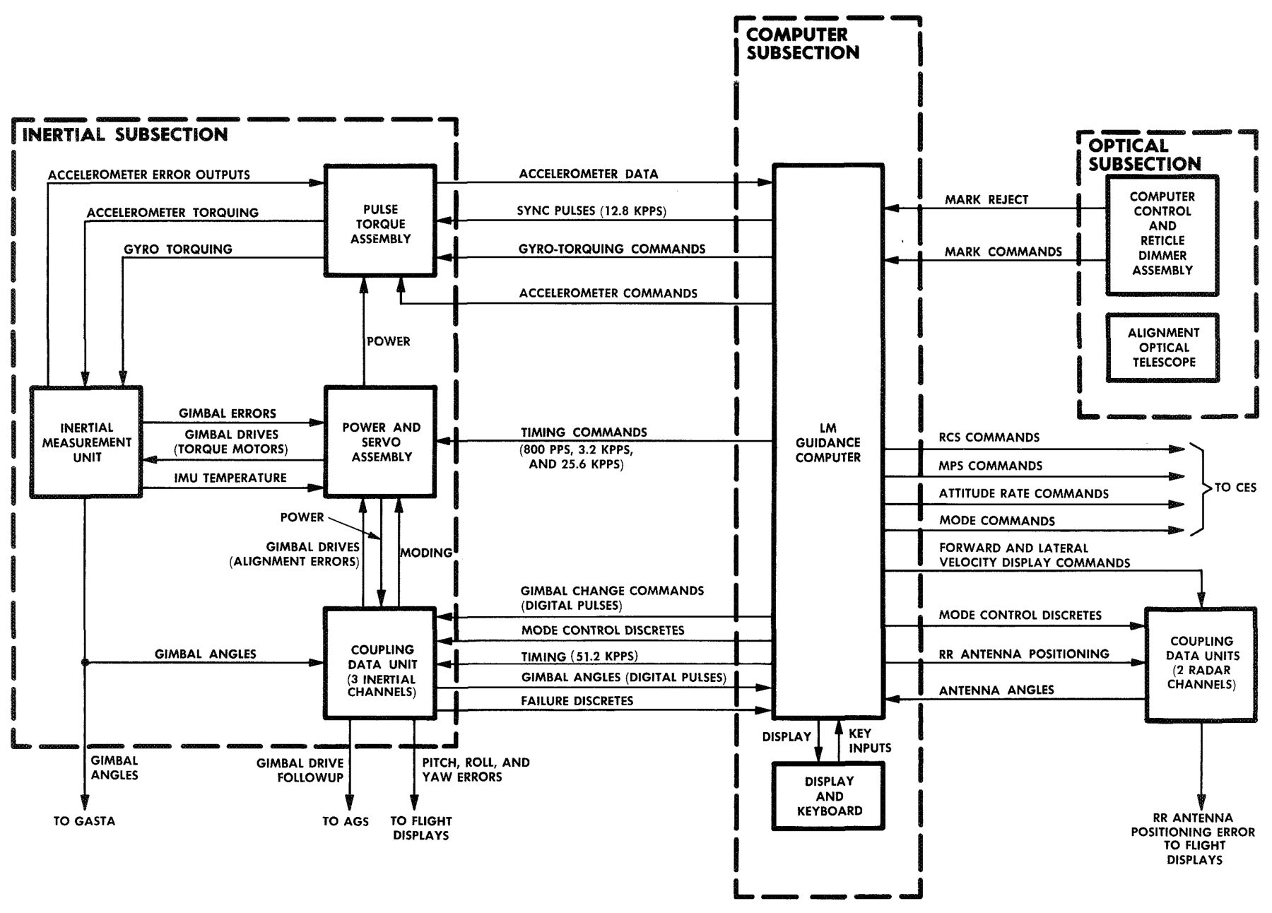
The PGNS included three major subsections: inertial, optical, and computer. Individually or in combination, they performed all the previously mentioned functions.
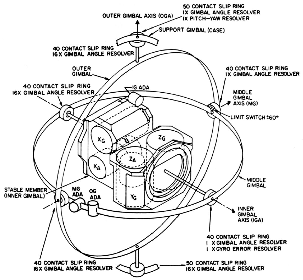
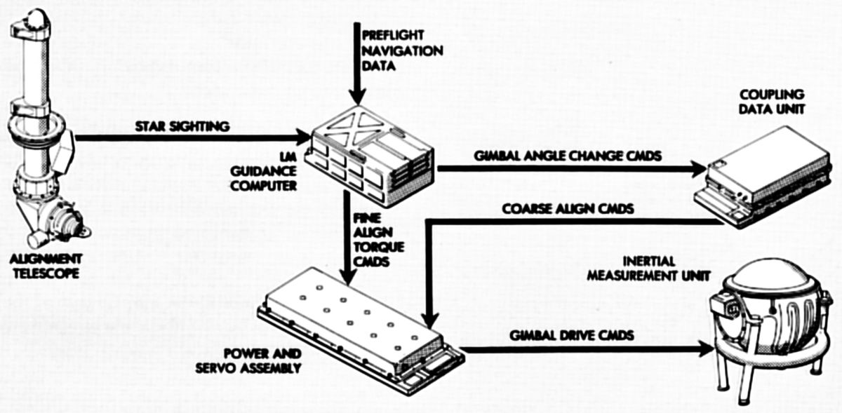
The inertial subsection (ISS) established the inertial reference frame that was used as the central coordinate system from which all measurements and computations were made. The ISS measured attitude and incremental velocity changes, and assisted in converting data for computer use, onboard display, or telemetry. Operation was started automatically by a guidance computer or by an astronaut using the computer keyboard. Once the ISS was energized and aligned to the inertial reference, any LM attitude change was sensed by the stable platform. All velocity and attitude inertial measurements were with respect to the stable platform. These data were used by the lunar module guidance computer (LGC) to determine guidance solutions. The ISS consisted of a navigation base, an inertial measurement unit (IMU), a coupling data unit, a pulse torque assembly, a power and servo assembly, and a signal conditioner assembly.
The optical subsection (OSS) was used to determine the LM's position using a star catalog stored in the LGC and celestial measurements made by an astronaut. The celestial objects in the star catalog were determined before earth launch. The astronaut used the AOT to take direct visual sightings and precise angular measurements of a celestial object pair. The computer subsection (CSS) used this data, along with pre-stored data, to compute position and velocity, and to align the inertial components. The AOT and a computer control and reticle dimmer (CCRD) assembly comprised the OSS.
The CSS, as the LM control and data-processing center, performed all the guidance and navigation functions necessary for automatic LM flight path and attitude control. The CSS used the LGC, a digital control computer with many general-purpose computer features, to accomplish these functions. The LGC aligned the stable platform and positioned both radar antennas. It also provided control commands to both radars, the ascent engine, the descent engine, the RCS thrusters, and the LM cabin displays. As a general-purpose computer, it solved mission guidance problems. The CSS consisted of a LGC and a display and keyboard (DSKY), which was a computer control panel.
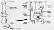
The navigation base was a lightweight (~ 3 lb) mount that supported, in accurate alignment, the IMU, AOT, and an abort sensor assembly (ASA). It had a center ring structure with four legs extending from its sides. The IMU was mounted to the legs at one end; the AOT and ASA the opposite side.
2.1 ISS Inertial Measurement Unit
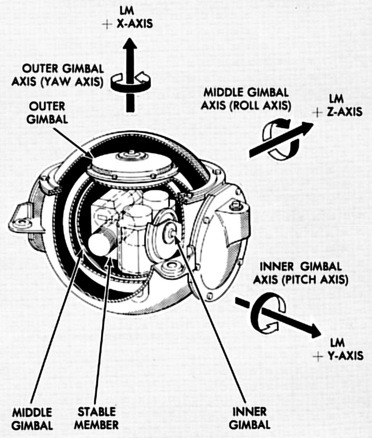
The IMU was the primary LM inertial sensing device. It comprised a three-degree-of-freedom gyroscope-stabilized platform that maintained an inertially-referenced coordinate system for LM attitude control and three accelerometers in the reference coordinate system for accurate velocity change measurements. The stable platform was supported by outer, middle, and inner gimbal rings for complete freedom of motion. Three mutually-perpendicular inertial reference integrating gyroscopes (IRIG) mounted on the stable platform sensed attitude changes. The fluid- and magnetically-suspended, single-degree-of-freedom IRIGs sensed rotation about the stable platform and generated error signals proportional to the rotation. Three fluid- and magnetically-suspended pulse integrating pendulous accelerometers (PIPA) sensed velocity changes.
2.2 ISS Command and Data Couplers
The coupling and data unit (CDU) converted and transferred angular information between the GNCS hardware elements by performing analog-to-digital and digital-to-analog conversion. Using five almost identical channels, the CDU processed the three inertial reference attitude angles and the two rendezvous radar (RR) antenna shaft and trunnion angles. The three IMU channels interfaced with the LGC, LSC and AGS. Each IMU gimbal angle resolver provided analog gimbal-angle signals that represented LM attitude. The CDU converted these signals to digital form and applied them to the LGC. The LGC calculated attitude or translation commands and routed them through the CES to the proper thruster. The CDU converted attitude error signals to 800-Hz analog signals and applied them to the FDAIs. Coarse- and fine-alignment commands generated by the LGC were coupled to the IMU through the CDU. The two channels used with the RR-to-LGC interface allowed the LGC to calculate digital antenna position commands before CSM acquisition. These signals, converted to analog form by the CDU, aimed the antenna via its drive mechanism. Analog tracking-angle information, converted to digital form by the CDU, was fed to the LGC.
The pulse torque assembly (PTA) supplied inputs to, and processed outputs from, the ISS inertial components.
The power and servo assembly (PSA) contained the power supplies that generated internal PGNS power, along with servomechanisms and temperature control circuitry for the IMU.
The signal conditioner assembly (SCA) interfaced the PGNS and the instrumentation subsystem. The SCA preconditiond PGNS measurements to 0 – 5 VDC levels before the signals were routed to the instrumentation subsystem.
2.3 ISS Alignment Optical Telescope
 |
 |
 |
| AOT Constuction, FoV, Reticle |
The AOT, an L-shaped periscope about 36" long, was used by the astronaut to take angular measurements between celestial objects. These angular measurements were required to orient the IMU during certain LM flight periods and during prelaunch preparations while the LM was on the lunar surface. Sightings taken with the AOT were transferred to the LGC by the astronaut, using the CCRD assembly. This assembly also controlled the telescope reticle pattern brightness.
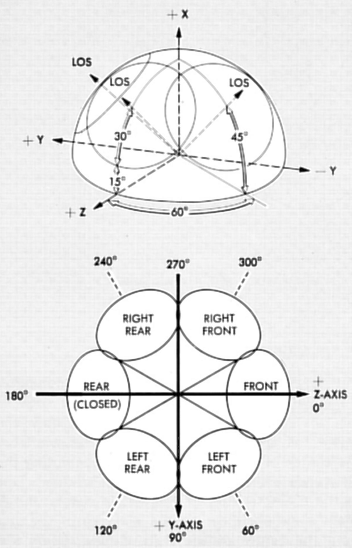
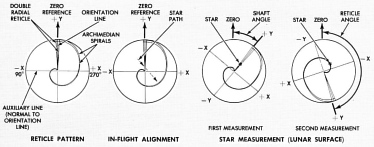
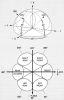
The AOT was a unity-power instrument with a 60° conical field of view. It had a movable shaft axis (parallel to the LM X-axis) and a LoS approximately 45° from the X-axis in the Y-Z plane. The LoS was fixed in elevation and movable in azimuth to six detent positions at 60° intervals. Detent positions were selected by turning a selector knob on the AOT. The reticle pattern within the eyepiece optics consisted of crosshairs and a pair of Archimedes spirals. The vertical crosshair, an orientation line designated the Y-line, was parallel to the X-axis when the reticle was at the 0° reference position. The horizontal crosshair, an auxiliary line designated the X-line, was perpendicular to the orientation line. The one-turn spirals were superimposed on the field-of-view center to the vertical crosshair top. Ten miniature red lamps mounted around the reticle prevented false star indications caused by reticle imperfections and illuminated the reticle pattern. Stars appeared white; reticle imperfections, red. Heaters prevented optics fogging due to moisture and low temperatures during the mission. A rotable eyeguard, fastened to the eyepiece end, was axially adjustable for head position. The eyeguard was used when the astronaut took sightings with his faceplate open, but was removed when the faceplate was closed and a fixed eyeguard, permanently cemented to the AOT, was used instead. The fixed eyeguard prevented the eyepiece from marring the helmet faceplate. An auxiliary high-density filter lens prevented eye damage if the sun was chosen as a reference.
The computer control and reticle dimmer assembly (CCRD) assembly was mounted on an AOT guard. Astronauts used the MARK X and MARK Y pushbuttons to send discrete signals to the LGC when star sightings were made. The REJECT pushbutton was used if an invalid mark has been sent to the LGC. A CCRD thumbwheel adjusted the telescope reticle lamp brightness.
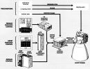
2.4 Lunar Guidance Computer
 |
| LGC, DSKY |
The LGC was the GNCS central data-processing device. The LGC, a control computer with many general-purpose computer features, processed data and issued discrete control signals for various subsystems. As a control computer, it aligned the IMU stable platform and provided LR and RR control commands and RR antenna drive commands. The LGC provided control commands to the ascent and descent engines, the RCS thrusters, and the cabin displays. As a general-purpose computer, it solved mission guidance problems and monitored PGNS operation.
The LGC stored data pertinent to the LM ascent and descent flight profiles. The LGC used these data (position, velocity, trajectory) to solve flight equations, which determined the required thrust magnitude and direction. The LGC activated the LM engines at the correct time and issued steering commands to orient the LM to a new trajectory, if required. The ISS sensed acceleration and supplied velocity changes to the LGC for calculating total velocity. The LGC supplied drive signals to the CDU and stabilization gyros in the ISS to align the gimbal angles in the IMU, which then supplied position signals indicating attitude changes to the LGC. The LGC provided antenna-positioning signals to the RR and received antenna angle information from the CDU RR channels. The LGC used this information for antenna-positioning calculations. During lunar-landing operations, star-sighting information was manually loaded into the LGC, using the DSKY. These data were used to calculate IMU alignment commands. The LGC and its programming helped meet the mission functional requirements. The functions performed during various mission phases included automatic and semiautomatic operations that were implemented mostly through programs stored in the LGC memory.
The DSKY allowed the astronaut to load information into the LGC, retrieve and display information contained in the LGC, and initiate any program stored in memory. The astronauts could also used the DSKY to control the ISS modes. The data exchange between the astronauts and the LGC was usually initiated by an astronaut; however, it could also be initiated by internal computer programs. The DSKY was located on panel 4, between the Commander and LM Pilot and above the forward hatch. The upper half was the display portion; the lower half the keyboard. The display portion contained five caution indicators, six status indicators, seven operation display indicators, and three data display indicators. These displays provide visual indications of data being loaded in the LGC, the LGC condition, and the program being used. The displays also provide the LGC with a means of displaying or requesting data.
The LGC and DSKY are discussed in greater detail in another section.
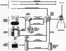
3.0 Abort Guidance Section
 |
| Abort Guidance Section |
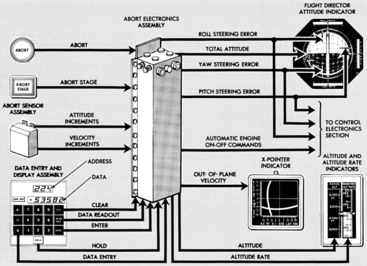
The AGS consisted of an abort sensor assembly (ASA), abort electronics assembly (AEA), and a data entry and display assembly (DEDA).
The ASA used gyros and accelerometers to provided incremental attitude and velocity change information around and along the LM X, Y, and Z axes. Data pulses were routed to the AEA, which used the attitude and velocity data to compute steering errors. The ASA consists of three strapped-down gyros, three strapped-down pendulous accelerometers, and associated electronic circuitry. The gyros and accelerometers (one each for each LM axis) sensed body-axis motion with respect to inertial space. The accelerometers sensed acceleration along the LM orthogonal axis. The gyros and accelerometers were securely fastened to the LM X, Y, and Z axes so that motion along or around one or more axis was sensed by one or more gyros and/or accelerometers. A strapped-down inertial guidance system had the advantage of substantial size and weight reduction over the more conventional gimbaled inertial guidance system, but had the disadvantage of error buildup over sustained operational periods. AGS calibration used PGNS reference data to determine the ASA gyro drift-compensation parameters. Calibration parameters stored in the AEA were used to correct calculations based on the gyro inputs.
Astronauts used the DEDA to select operational modes, insert targeting parameters, and monitor related data throughout the mission. The DEDA consisted of a control panel to which electroluminescent displays and data entry pushbuttons were mounted and an enclosure that housed logic and input/output circuits.
The AEA was a general-purpose, high-speed, 4,096 word digital computer that performed basic strapped-down guidance system calculations and the abort guidance and navigation steering calculations. The computer used a fractional two's complement, parallel arithmetic section, and parallel data transfer. The AEA had stabilization and alignment, navigation, and guidance computational sections. The stabilization and alignment computational section computed stabilization and alignment on generation of mode signals by the DEDA. These mode signals governed stabilization and alignment computational section operation in conjunction with the navigation and guidance computational sections. The navigation computational section used accelerometer inputs received from the ASA, via AEA input logic circuits, to calculate LM position and velocity in the inertial reference frame. The navigation computational section supplied total velocity, altitude, altitude-rate data, and lateral velocity data in the LM reference frame, to the output logic circuits. Velocity data were routed to the DEDA, altitude-rate data were routed to the ALT RATE indicator, and lateral velocity data were routed to the X-pointer indicators. Velocity and position data were routed to the guidance computational section for computing LM orbital parameters. The guidance computational section provided trajectory computation and selection, steering computation, and midcourse-correction computation. This computational section received CSM state vector and the LM state vector data from the LGC and other external source through the AGS input selector logic. Body-referenced steering errors for trajectory computation were received from the stabilization and alignment computational section. The abort guidance problem consisted of solving the equations for the selected guidance maneuver, including steering, attitude, and engine control computations. Guidance computational section output, through the output select logic circuits, included CES engine on/off signals and velocity to be gained (selectable by the DEDA). Functionally, the AEA consisted of a memory subassembly, central computer, an input/output subassembly, and a power subassembly.
4.0 Control Electronics Section
The CES comprised two attitude controller assemblies (ACAs), two translation/thrust controller assemblies (TTCAs), an attitude and translation control assembly (ATCA), a rate gyro assembly (RGA), descent engine control assembly (DECA) , and three stabilization and control (S&C) control assemblies.
 |
 |
Lunar Module Pilot's Station,
ACA Detail |
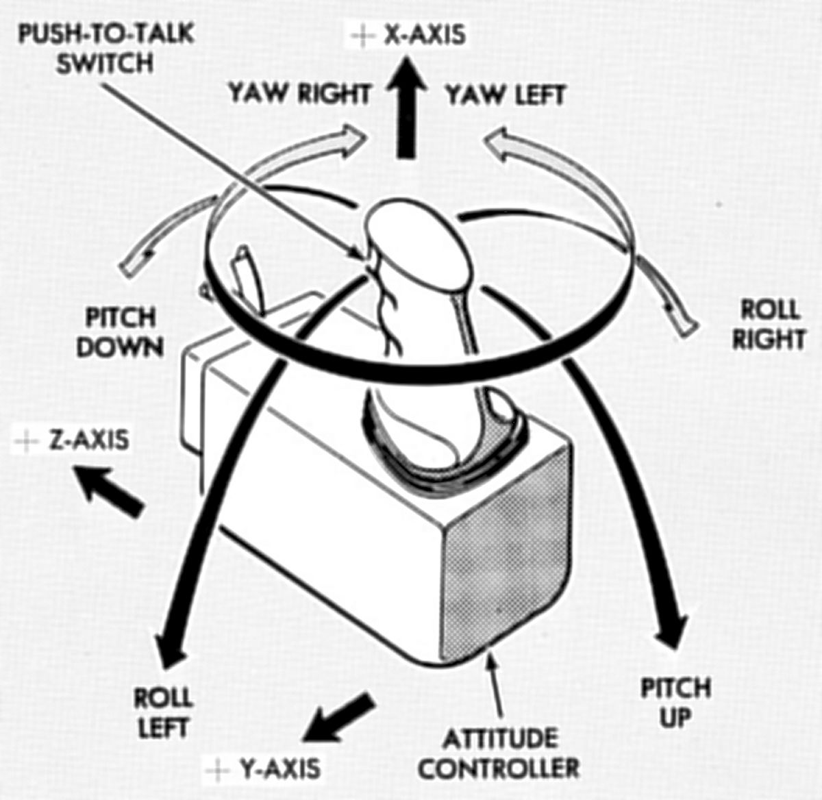
The ACAs were right-hand pistol grip controllers, which the astronauts used to command changes in LM attitude. Each ACA was installed with its longitudinal axis approximately parallel to the X-axis. It supplied the LGC and ATCA attitude-rate commands proportional to its handle displacement, along with an out-of-detent discrete each time the handle was out of its neutral position and a follow up discrete to the AGS each time the controller was out of detent. A push-to-talk trigger switch on the ACA pistol grip handle was used for CSM and ground facility communication. When the astronaut used his ACA, his hand movements were analogous to LM rotations. Clockwise or counterclockwise controller rotation commanded yaw right or yaw left. Forward or aft controller movement commanded LM pitch down or up. Left or right controller movement commanded roll left or right.
The ACAs were also used in an incremental landing point designator (LPD) mode, which was available to the astronauts during the final approach phase. In this mode, the angular error between the designated landing site and the desired landing site was nailed by repetitive manipulation of an ACA. LPD signals from the ACA were directed to the LGC, which issued commands to move the designated landing site incrementally along the Y-axis and Z-axis.
 |
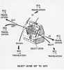 |
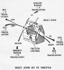 |
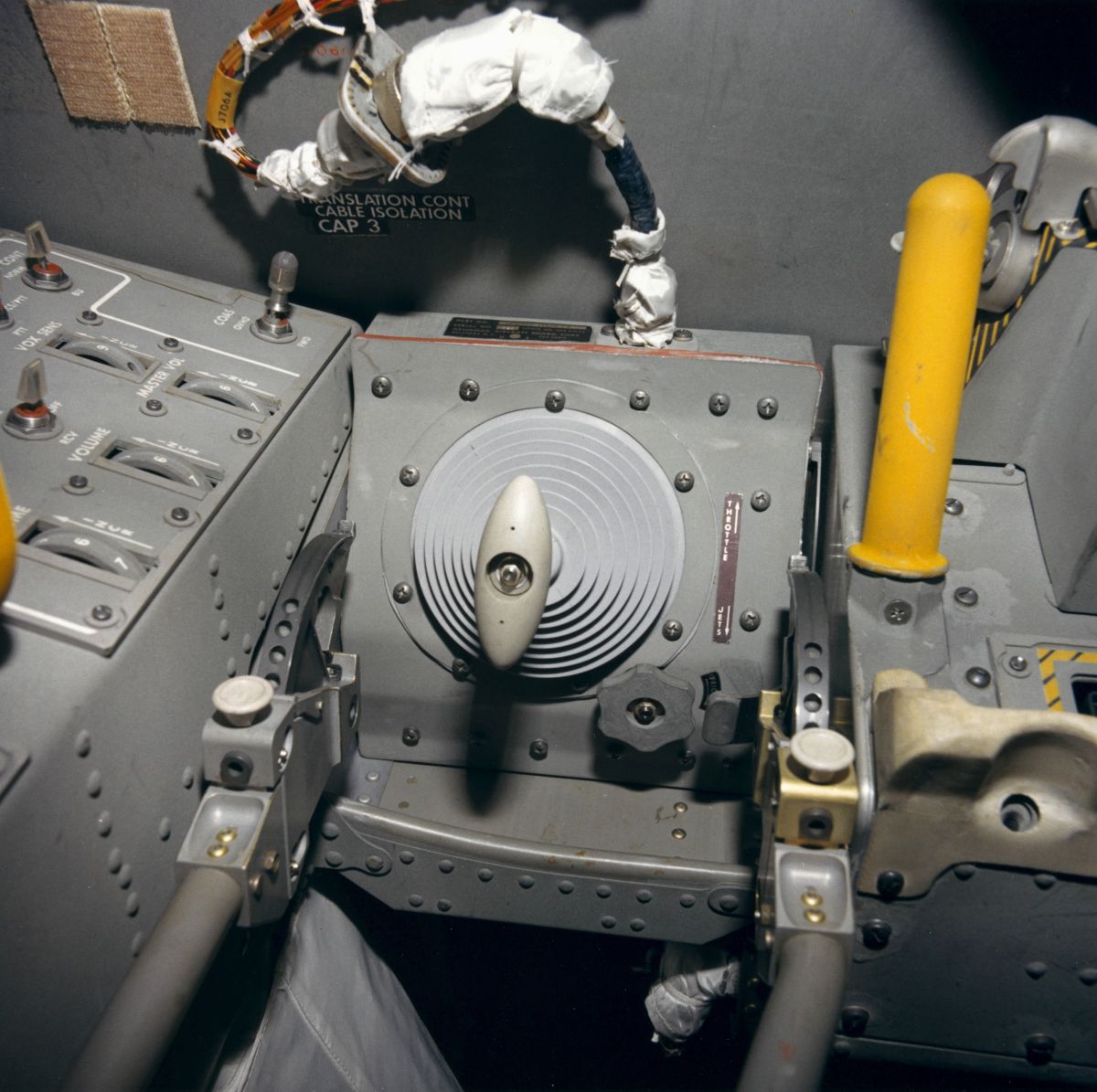
| Translation/Thrust Controller Assembly |
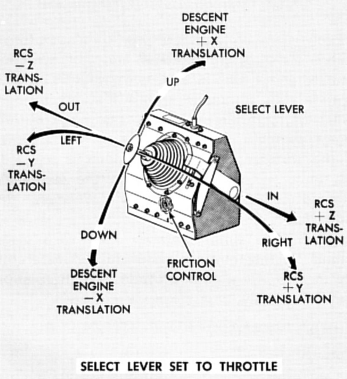
The TTCAs were functionally-integrated translation and thrust controllers that managed LM translation in any axis. The astronauts used the TTCAs to command LM translations by firing RCS thrusters and to throttle the descent engine thrust between 10% and 92.5%. The controllers were three-axis, T-handle, left-hand controllers, mounted with their longitudinal axis approximately 45° from a line parallel to the LM Z-axis (forward axis). A lever on the TTCA right side selected either (1) translation control in the Y-axis and Z-axis using the RCS thrusters and descent engine throttling to control X-axis translation and (2) translation control in all three axes using the RCS thrusters. Due to the TTCA mounting position, LM translations correspond to astronaut hand movements when operating the controller. Moving the T-handle to the left or right commanded translation along the Y-axis. Moving the T-handle inward or outward commands translation along the Z-axis. Moving the T-handle upward or downward commands translation along the x-axis, using the RCS thrusters when the select lever was in the down position. When the lever was in the up position, upward or downward TTCA movement increased or decreased the descent engine thrust. The TTCA was spring loaded to its neutral position in all axes when the lever was in the jets position. When the lever was in the throttle position, the Y- and Z-axis movements were spring loaded to the neutral position but the X-axis throttle commands will remain at the position set by the astronauts.
The ATCAs controlled LM attitude and translation. In the primary guidance path, attitude and translation commands were generated by the LGC and applied directly to drivers within the assembly. In the abort guidance path, the ATCA received translation commands from a TTCA, rate-damping signals from the RGA, and attitude rate commands and pulse commands from the ACA. The ATCA combined attitude and translation commands in its logic network to select the proper thruster to be fired for the desired translation and/or rotation. In the primary control mode the ATCA routed the RCS thruster on/off commands from the LGC to the thrusters. During abort guidance control, the ATCA computed which RCS thrusters were to be fired.
The RGA supplied the ATCA with damping signals to limit LM rotation rates and facilitated manual rate control during abort guidance control.
The DECA processed engine-throttling commands from the astronaut (manual control) and the LGC (automatic control), gimbal commands for thrust vector control, preignition (arming) commands, and on/off commands to control descent engine operation. The DECA accepted engine-on and engine-off commands from the S&C control assemblies, throttle commands from the LGC and the TTCA, and trim commands from the LGC or the ATCA. Demodulators, comparators, and relay logic circuits converted these inputs to the required descent engine commands. The DECA applied throttle and engine control commands to the descent engine and routed trim commands to the gimbal drive actuators.
The S&C Control Assemblies processed, switched, and/or distributed the various signals associated with the GNCS.
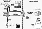
5.0 GNCS Functional Description
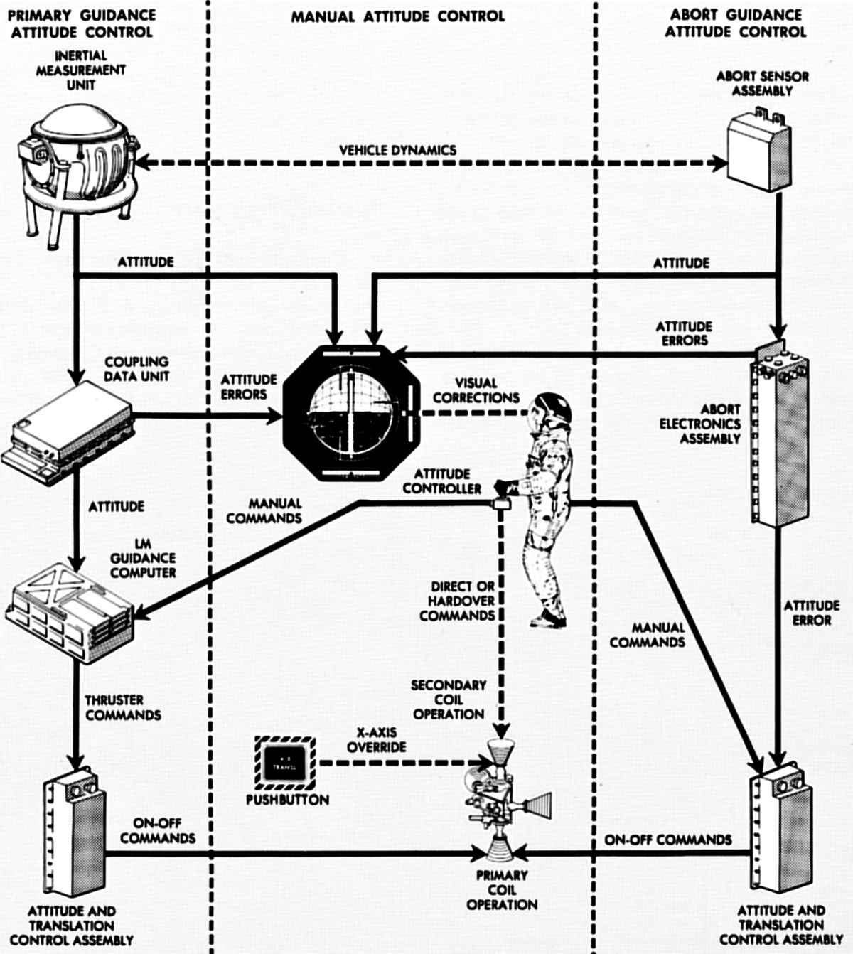
Two function loops composed the GNCS, each of which was an independent guidance and control path. The primary guidance path performed all functions to complete the lunar mission. If a failure occurred in the primary guidance path, the abort guidance path could be substituted.
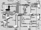 |
| Primary Guidance Path |
The primary guidance path comprised the PGNS, CES, LR, RR, and the selected propulsion section(s). The CES routed flight control commands from the PGNS and applied them to the descent or ascent engine, and/or the appropriate thrusters. The IMU, which continuously measured attitude and acceleration, was the primary LM inertial sensing device. The LR sensed slant range and velocity. The RR tracked the CSM to derive LoS range, range rate, and angle rate. The LGC used AOT star-sighting data to align the IMU. Using inputs from the IMU, LR, RR, TTCAs, and ACAs, the LGC solved guidance, navigation, steering, and stabilization equations necessary to initiate descent and ascent engine on/off commands, descent engine throttle and trim commands, and thruster on/off commands.
LM control using the primary guidance path ranged from fully automatic to manual. The primary guidance path operated in the automatic mode or the attitude hold mode. In the automatic mode, all navigation, guidance, stabilization, and control functions were controlled by the LGC. When the attitude hold mode was selected, the astronaut used his ACA to bring the LM to a desired attitude. When the ACA was moved from its detent position, proportional attitude-rate or minimum impulse commands were routed to the LGC. The LGC then calculated steering information and generated thruster commands that correspond to the operation mode selected via the DSKY. These commands were applied to the primary preamplifiers in the ATCA, which routed the commands to the proper thruster. When the astronaut released the ACA, the LGC generated commands to hold this attitude. If the astronaut command ACA four-jet direct operation by going to the hardover position, the ACA applied the command directly to the corresponding thruster's secondary solenoids.
In automatic mode, the LGC generated descent engine throttling commands, which were routed to the descent engine via the DECA. The astronaut could manually control descent engine throttling with his TTCA. The DECA summed the TTCA throttle commands with the LGC throttle commands and applied the resultant signal to the descent engine. The DECA also applied trim commands, generated by the LGC, to the gimbal drive actuators (GDAs), providing descent engine trim control. The LGC supplied on/off commands for the ascent and descent engines to the S&C control assemblies, which routed the ascent engine on/off commands directly to the ascent engine, and the descent engine on/off commands to the descent engine via the DECA. The LGC generated +X-axis translation commands to provide ullage maneuver acceleration. In the manual mode, manual translation commands were generated by the astronaut, using his TTCA. These commands were routed, through the LGC, to the ATCA and on to the proper thruster(s).
 |
 |
| Abort Guicance Path |
Abort Functions |
The abort guidance path comprised the AGS, CES, and the selected propulsion section(s). The AGS performed all inertial navigation and guidance functions necessary to affect a safe orbit or CSM rendezvous. The stabilization and control functions were performed in the CES by analog computation techniques.
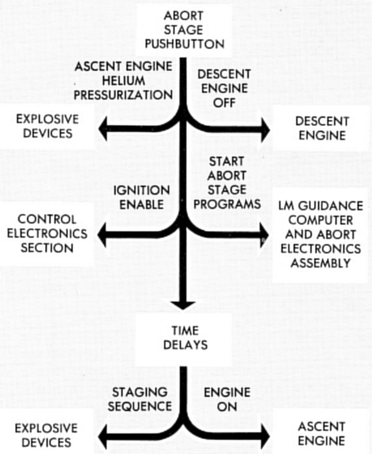
Attitude and acceleration from the ASA was processed by the AEA, which made steering control calculations. The CES functioned as an analog autopilot when the abort guidance path was selected. It used inputs from the astronauts and the AGS to provide:
- descent engine on/off and TTCA throttling commands
- gimbal commands for the GDAs to control descent engine trim
- ascent engine on/off commands
- sequence logic to ensure proper arming and staging before engine startup and shutdown
- thruster on/off commands for translation and stabilization
- logic to select the proper thrusters for the various maneuvers
- LM control modes ranging from fully automatic to manual.
Astronauts used the TTCA to control descent engine throttling and translation maneuvers. The throttle commands, engine on/off commands from the S&C control assemblies, and trim commands from the ATCA were applied to DECA. The DECA applied the throttle commands to the descent engine, the engine on/off commands to the descent engine latching device, and the trim commands to the GDAs. The S&C control assemblies received engine on/off commands for the descent and ascent engines from the AEA. As in the primary guidance path, the S&C control assemblies routed descent engine on/off commands to the DECA and applied ascent engine on/off commands directly to the ascent engine.
The abort guidance path operated in automatic or attitude hold modes. In the automatic mode, navigation and guidance functions were controlled by the AGS, stabilization and control functions by the CES. In the attitude hold mode the astronaut used his ACA to control LM attitude. The ACA generated attitude-rate, pulse, direct, and hardover commands. The attitude-rate and pulse commands, AEA error signals, RGA rate-damping signals, and TTCA translation commands were applied to the ATCA. The ATCA processed these inputs to generate thruster on/off commands
In the attitude hold mode, pulse and direct submodes were available for each axis. The pulse submode was an open-loop attitude control mode in which the ACA was used to make small attitude changes in the selected axis. The direct submode was an open-loop attitude control mode in which pairs of thrusters were directly controlled by the ACA. The astronaut could also control LM attitude in any axis by moving the ACA to the hardover position. In addition, the astronaut could override translation control in the +X-axis with a +X-axis translation pushbutton; pressing the pushbutton fired all four +X-axis thrusters.
GNCS Function Control Diagrams
 |
 |
 |
 |
 |
 |
 |
| Ascent Engine |
Attitude |
Descent Engine |
Flight |
Inertial Alignment |
Inertial Subsystem |
Translation |
6.0 Radar Subsystem
During the landing phase and subsequent rendezvous phase, the LM used radar navigational techniques to determine distance and velocity. Each flight phase used a radar designed for that phase. Both radars informed the astronaut and the computer concerning position and velocity relative to acquired target. During lunar landing, the target was the lunar surface; during rendezvous, the target was the CSM.
 |
| Landing Radar Antenna |
The landing radar (LR), located on the descent stage, provided altitude and velocity data during lunar descent. The primary guidance and navigation section calculated control signals for descent rate, hovering, and safe landing. For the LM, altitude data acquisition began at about 38,000 feet above the lunar surface; velocity data at about 25,000 feet. The landing radar used four microwave beams: three, to measure velocity by Doppler shift continuous wave; one, to measure altitude by continuous-wave frequency modulation. The LGC received these data as 15-bit binary words. DC analog voltages representing forward and lateral velocity data were provided to the displays, and range and range rate data was provided to the displays as pulse-repetition frequencies.
Antenna and electronics assemblies comprised the landing radar. The antenna assembly formed, directed, transmitted, and received the four microwave beams. Two interlaced phased arrays transmitted the velocity and altimeter-beam energy. Four broadside arrays received the reflected beam energy. The electronics assembly processed the Doppler and continuous-wave FM returns, which provided the velocity and slant range data for the LGC and displays. The antenna assembly transmitted 10.51 GHz velocity beams and a 9.58 GH altimeter beam to the lunar surface. When the electronics assembly was receiving and processing the returned microwave beams, data-good signals were sent to the LGC; when the electronics assembly was not operating properly, data-no-good signals were sent to the Instrumentation Subsystem pulse-code-modulation and timing electronics assembly for telemetry.
Using controls and indicators, the astronauts could:
- Monitor LM velocity, altitude, radar-transmitter power and equipment temperatures
- Apply power to energize the radar
- Initiate self-test
- Place the antenna in the descent or hover position.
Self-test permitted operational radar checks without radar returns from external sources. An antenna temperature control circuit, energized at earth launch, protected antenna components against the low temperatures of space while the radar was not operating. The radar was first turned on and self-tested during LM checkout before separation from the CSM. The self-test circuits applied simulated Doppler signals to radar velocity sensors, and simulated lunar range signals to an altimeter sensor. The radar was self-tested again immediately before powered descent, about 70,000 feet above the lunar surface. The radar operated from about 50,000 feet until lunar touchdown. Altitude (derived from slant range) and forward and lateral velocities were available to the LGC and cabin indicators. Slant range data were continuously updated to provide true altitude above the lunar surface. At about 200 feet above the lunar surface, the LM pitched to orient its X-axis perpendicular to the surface; all velocity vectors were near zero. Final visual landing site selection was followed by touchdown under automatic or manual control. During this phase, the astronauts monitored altitude and velocity data from the radar. The landing radar antenna had a descent position and a hover position. In the descent position, the antenna boresight angle was 24° from the LM X-axis, In the hover position, the antenna boresight was parallel to the X-axis and perpendicular to the Z-axis. The astronaut selected antenna position during manual operation and the LGC selected antenna position during automatic operation. During automatic operation, the LGC commanded the antenna to the hover position 5,000 to 9,000 feet above the lunar surface.
The landing radar antenna assembly comprised four microwave mixers, four dual audio-frequency preamplifiers, two microwave transmitters, a frequency modulator, and an antenna pedestal tilt mechanism. The antenna consists of six planar arrays, two for transmission and four for reception. They were mounted on the tilt mechanism beneath the descent stage, and could be placed in one of two fixed positions.
The electronics assembly comprised frequency trackers (one for each velocity beam), a range frequency tracker, velocity converter and computer, range computer, signal data converter, and data-good/no-good logic.
 |
Rendezvous
Radar Antenna |
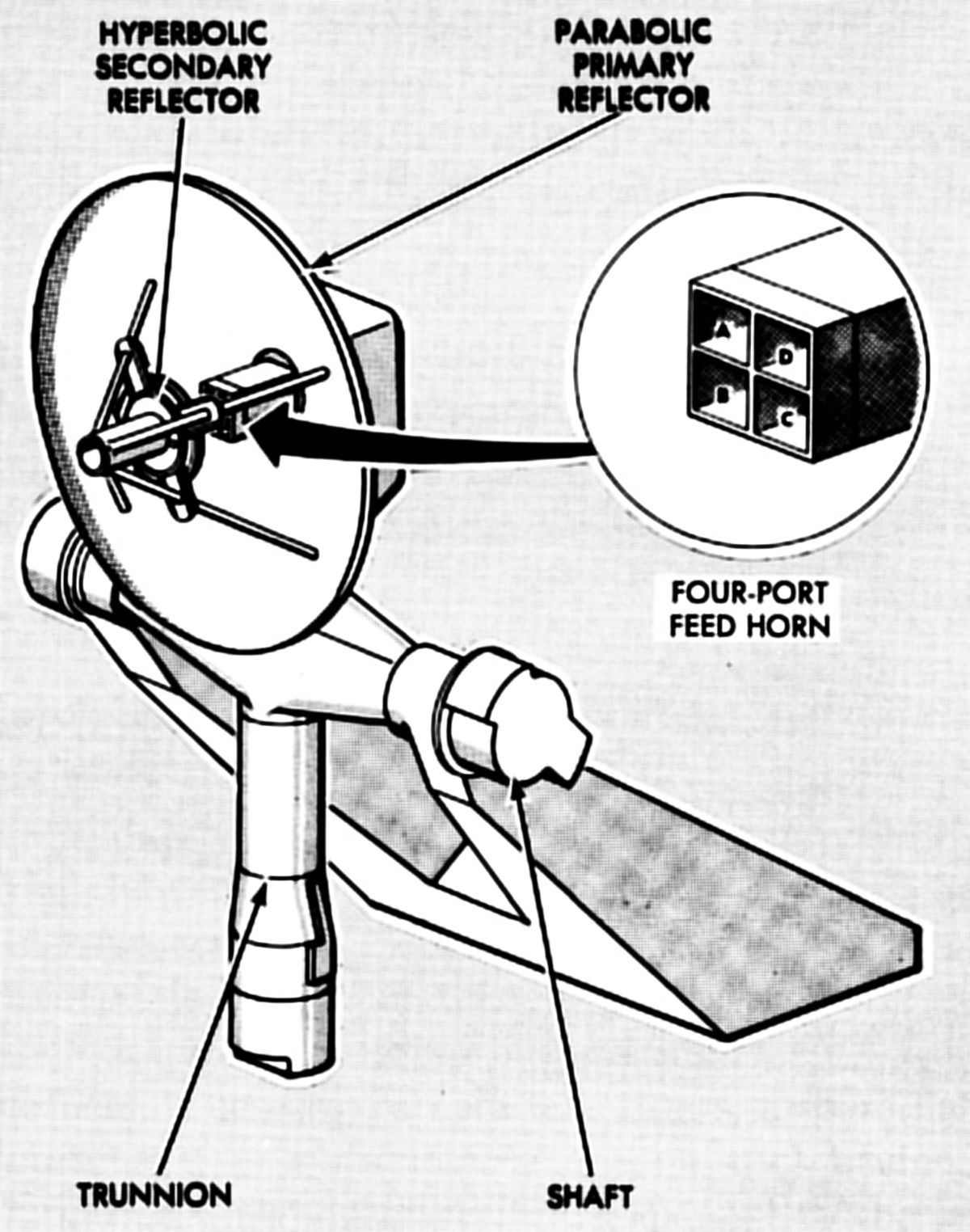
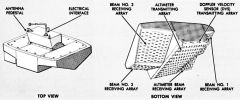
The rendezvous radar, which operated in conjunction with a CSM transponder, acquired and tracked the CSM before and during rendezvous and docking. The radar, located in the ascent stage, tracked the CSM during the mission descent phase to supply tracking data for any required abort maneuver and during the ascent phase to supply data for rendezvous and docking. When the radar tracked the CSM, continuous measurements of range, range rate, angle, and angle rate (with respect to the LM) were provided simultaneously to the PGNS and to LM cabin displays. This allowed rendezvous to be performed automatically under computer control, or manually by the astronauts. During the rendezvous phase, rendezvous radar performance was evaluated by comparing radar range and range rate tracking values with MSFN tracking values.
The CSM transponder received an X-band three-tone phase-modulated, continuous-wave signal from the rendezvous radar, offset the signal by a specified amount, and then transmitted a phase-coherent carrier frequency for acquisition by the radar. This return signal made the CSM appear as the only object in the radar field of view. The transponder provided the long range (400 nm) required for the mission.
The transponder and the radar used solid-state high-reliability varactor frequency-multiplier chains as transmitters. The radar antenna was space stabilized to negate the effect of LM motion on the line-of-sight angle. The rate-integrating gyros used for this also supply the astronauts accurate line-of-sight, angle-rate data in the manual mode. Range rate was determined by measuring the two-way Doppler frequency shift on the signal received from the transponder. Range was determined by measuring the time delay between the received and the transmitted three-tone phase-modulated waveform. Component groups, mounted opposite one another on the trunnion axis, revolved about the shaft axis. This balanced arrangement required less driving torque and reduced the overall antenna weight. The microwave, radiating, and gimbaling components, and other internally mounted components, had low-frequency flexible cables that connected the outboard antenna components to the inboard electronics assembly.
The electronics assembly comprised a receiver, frequency synthesizer, frequency tracker, range tracker, servo electronics, a signal data converter, self-test circuitry, and a power supply. The assembly furnished crystal-controlled signals, which drove the antenna assembly transmitter, provided a reference for receiving and processing the return signal, and supplied signals for antenna positioning.
References
Lunar Module LM 10 through LM 14 Vehicle Familiarization Manual LMA790-2 (Bethpage, New York: Grumman Aerospace Corporation, 1 Nov 1969).
Lunar Module News Reference (Bethpage, New York: Grumman Aircraft Engineering Corp., 1966).