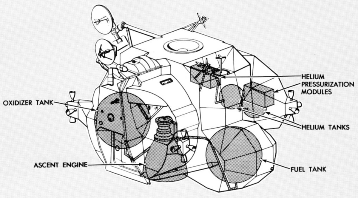
APS Component Location
U.S. Manned Rocket Propulsion Evolution
Part 9.43: The Lunar Module Ascent Propulsion System (APS)
Compiled by Kimble D. McCutcheon
Published 28 Dec 2021; Revised 4 Aug 2022
APS Component Location |
The LM ascent propulsion system (APS) boosted the LM ascent stage from the moon's surface into lunar orbit. The APS operated in concert with the LM reaction control subsystem (RCS), which enabled precise attitude and translation maneuvers. The APS propellant tanks were connected to the RCS to supplement its propellant supply during certain mission phases. If the descent was aborted, either the ascent or descent engine was available for return to a CSM rendezvous orbit. The choice of engines depended on the abort cause, descent stage propellant remaining, and length of time the descent engine had been firing. |
|
Description
The APS consisted of a hypergolic-liquid-propellant, fixed-thrust, 3,500 lbT, restartable, pressure-fed rocket engine, one fuel tank, one oxidizer tank, two helium tanks, and associated propellant feed and helium pressurization components. Redundant components in each subsystem enhanced reliability. Pressurized helium forced hypergolic propellants from storage tanks to the engine injector. Gases produced by combustion passed through a throat area into the engine nozzle, where they expanded to an extremely high velocity before being ejected. The exhaust gas momentum produced the reactive force that propelled the vehicle.
Pressurization Subsystem
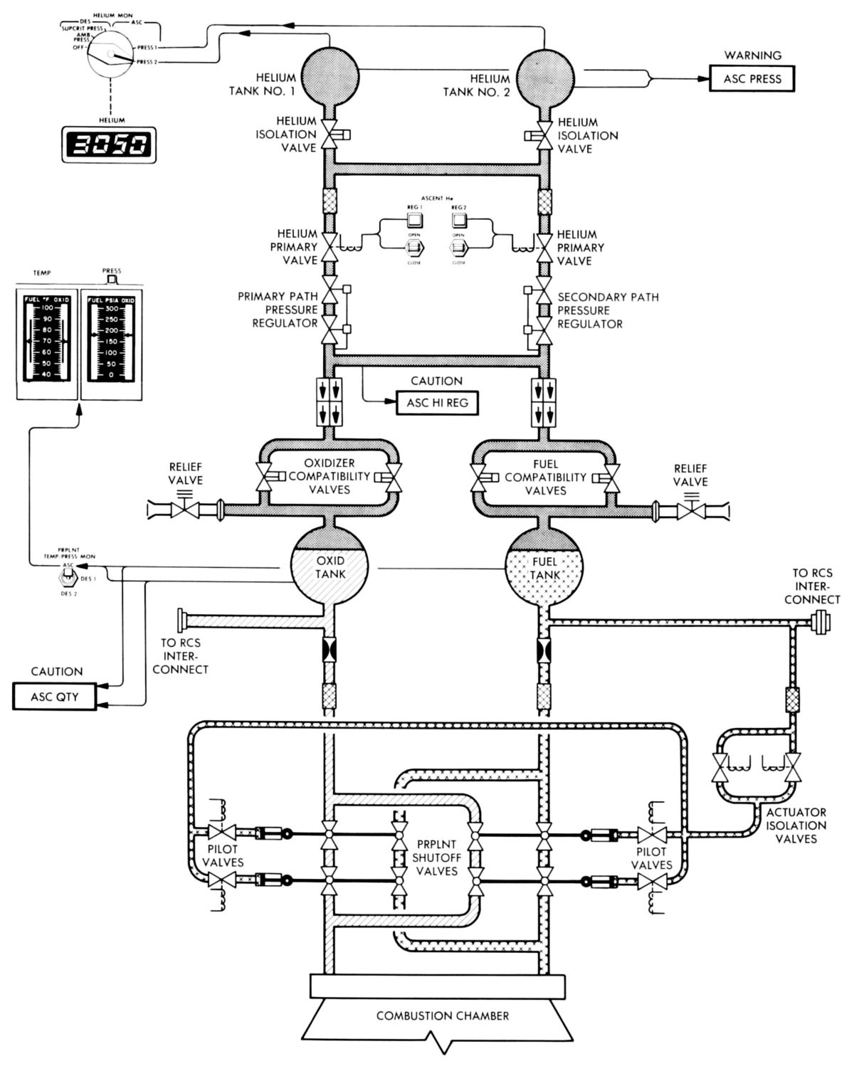
Before ascent engine start its propellant tanks had to be fully pressurized with gaseous helium, which was stored in two identical tanks that were made by Sargent Industries, Airite Division, El Segundo, California. An explosive valve at each helium tank's outlet prevented helium from leaving the tanks until shortly before APS use. Astronauts normally fired two helium isolation valves and four propellant compatibility valves simultaneously to open helium paths to the propellant tanks. Before firing the explosive valves, astronauts checked the pressure in each helium tank. If one tank showed an unusually low reading (indicating leakage), they excluded the appropriate helium isolation explosive valve from the fire command. This isolated the faulty tank from the pressurization system and prevented helium loss through the leaking tank via the helium interconnect line.
The primary and secondary helium flow paths merged downstream of the regulators, forming a common helium manifold that fed both oxidizer and fuel tanks. A quadruple check-valve assembly isolated upstream components from the corrosive propellant vapors and prevented potential hypergolic action in the common manifold that could have resulted from propellants or propellant vapor mixing from tank backflow.
Two parallel explosive valves downstream of each quadruple check-valve assembly provide a positive seal upstream from the propellant tanks, thereby isolating the fuel and oxidizer (liquid and vapor) before the initial ascent-engine start. This configuration reduced compatibility problems involving helium components and prolonged pressurization-system component life. Just upstream from the fuel and oxidizer tanks, each helium flow path contained a burst-disk relief-valve assembly capable of passing the entire helium flow from a failed-open regulator pair without damaging the propellant tanks.
Each propellant flowed through a trim orifice to a propellant filter in the engine assembly, then to the isolation and bipropellant valve assemblies (propellant-shutoff valves). The trim orifice provided an engine-interface pressure of 170 psia for proper engine propellant utilization. A secondary distribution line was interconnected to the reaction control system (RCS). A series-parallel RCS/APS interconnect solenoid valves (part of the RCS) permitted the RCS to burn APS propellants, providing the APS was pressurized and the propellant was settled during the time the interconnect valves were opened.
Propellant Feed Subsystem
The APS oxidizer and fuel tanks, built by the Aerojet General Corporation Downey Plant in Downey, California, had provisions for astronauts to monitor propellant temperature and ullage pressure. Helium flowed into the propellant tank tops where diffusers uniformly distribute it throughout the ullage space. The outflow from each propellant tank divided into two paths. The primary path routed each propellant through a trim orifice and a filter to the engine assembly propellant shutoff valves. The trim orifice provided an engine inlet pressure of 170 psia for proper propellant use. The secondary path connected the ascent propellant supply to the RCS. This interconnection permitted the RCS to burn ascent propellants, providing the ascent tanks were pressurized and the ascent or descent engine was operating when the RCS thrusters were fired. A line branching off the RCS interconnect fuel path led to two parallel actuator isolation solenoid valves. This line routed fuel to the engine pilot valves that actuated the propellant shutoff valves.
 |
 |
| Flow Diagram | Control Diagram |
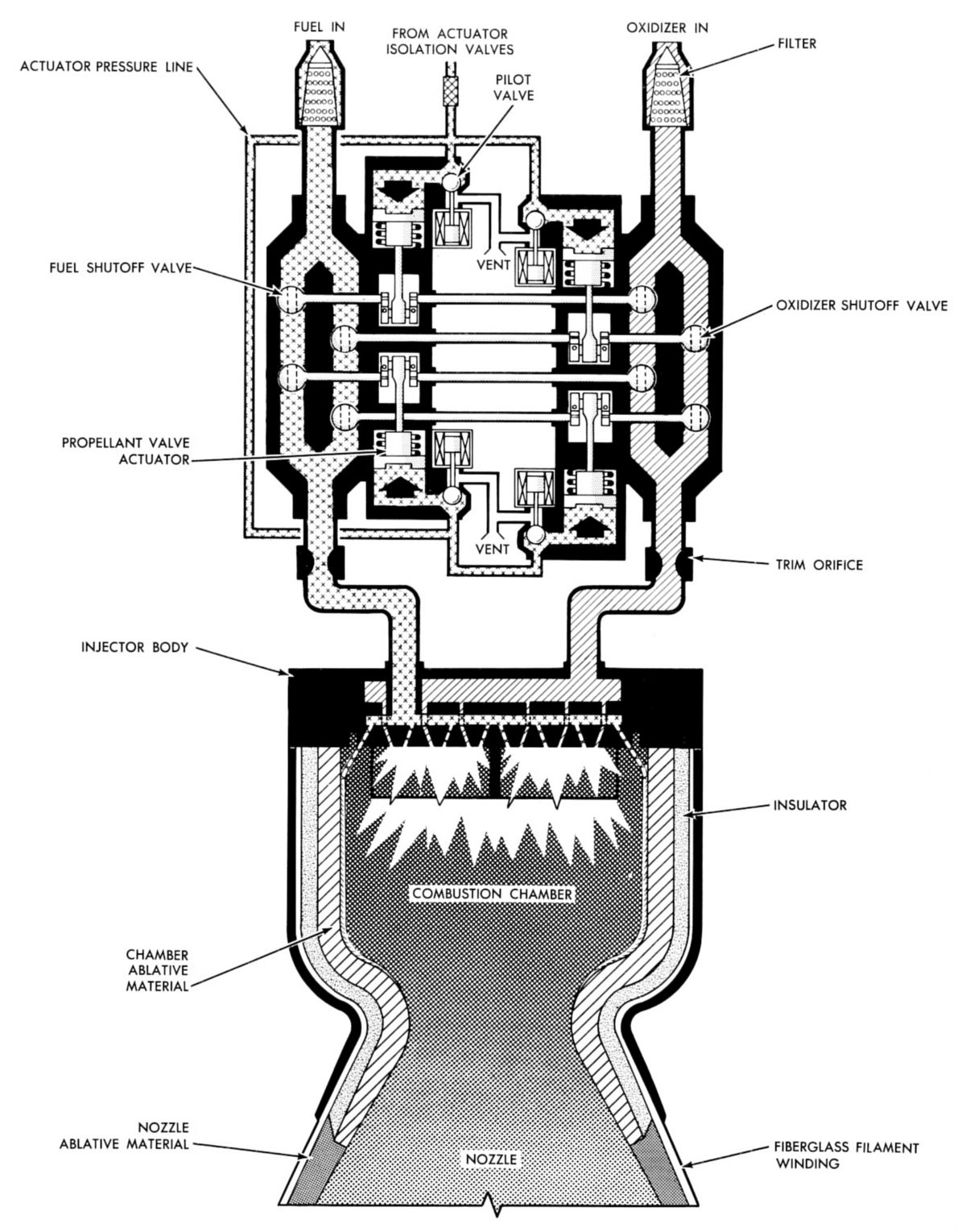
Lunar Module Ascent Engine (LMAE)
 |
 |
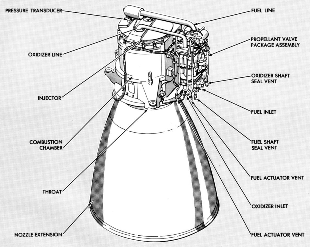
| Components | Flow Diagram |
The LMAE was built by North American Rockwell, Rocketdyne Division, Canoga Park, California, using nozzle and valve designs and components from Bell Aerosystems Company of Buffalo, New York. The LMAE was installed in the ascent stage midsection so that its centerline was 1.5° from the X-axis, in the +Z-direction, thus compensating for structural flex when the engine fired. Fuel and oxidizer entering the engine assembly were routed through filters, propellant shutoff valves, and trim orifices, to the injector where hypergolic ignition occurred in the combustion chamber. A separate fuel path led from the actuator isolation values to the pilot valves where it opened the propellant shutoff valves.
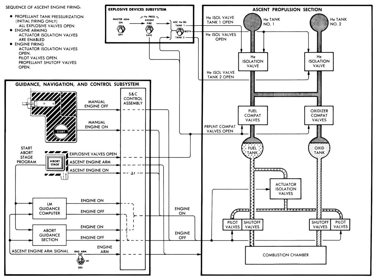
Propellant flow into the combustion chamber was controlled by a valve package assembly, trim orifices, and the injector. The valve package assembly consisted of eight propellant shutoff valves arranged in series-parallel redundant fuel-oxidizer pairs. Each pair was operated from a single crankshaft by its actuator. When an engine-start command was received, the two actuator isolation valves and the four pilot valves opened simultaneously. Fuel then flowed through the actuator pressure line and the four pilot valves into the actuator chambers. Hydraulic pressure extended the actuator pistons, cranking the propellant shutoff valves 90° to the fully open position. The propellants then flowed through the shutoff valves and a final set of trim orifices to the injector. The orifices trimmed the fuel and oxidizer pressure differentials to establish the propellant mixture ratio. The injector's physical characteristics created an oxidizer lead of approximately 50 milliseconds, precluding a rough engine start possibility with a fuel lead.
At engine shutdown, the actuator isolation valves closed, preventing additional fuel from reaching the pilot valves. Simultaneously, the pilot valve solenoids were de-energized, opening the actuator ports to overboard vents that conveyed residual actuator fuel into space. With the actuation fuel pressure removed, the actuator pistons were forced back by spring pressure, cranking the propellant shutoff valves to the closed position.
APS Operation and Control
Shortly before ascent engine use, the astronauts fired explosive valves to pressurize the APS. The ascent engine, like the descent engine, required manual arming before it could be fired. When the ascent engine was armed, a shutoff command was sent to the descent engine, followed by enabling signals to the ascent engine control circuitry, permitting manual- or computer-initiated ascent engine start. Astronauts used the same start and stop pushbuttons as for the descent engine. For automatic start, the GN&C stabilization and control generated sequential control of LM staging and ascent engine commands. The initial ascent engine firing — whether for normal lunar surface lift-off or in-flight abort — occurred while the ascent and descent stages were still mated, although no longer mechanically secured to each other. If, during the descent trajectory, an abort situation necessitated using the ascent engine to return to the CSM, the sequence resulted in an immediate descent engine shutdown followed by a time delay to ensure that the engine has stopped thrusting before staging occurred. The next command automatically pressurized the ascent propellant tanks, followed by staging. This resulted in severing the hardware securing the ascent stage to the descent stage and the interconnecting cables. The ascent engine fire command completed the abort stage sequence.
APS Equipment
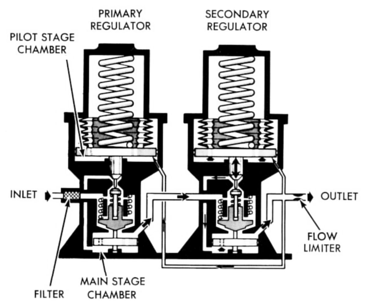
Helium Pressure Regulator Assemblies
 |
| Helium Pressure Regulator |
Each helium pressure regulator assembly consisted of two individual pressure regulators connected in series. The downstream regulator was set to produce a higher outlet pressure so that it was only active if the upstream regulator (primary unit) failed open. Each pressure regulator consisted of a direct-sensing main stage and a pilot stage. The main stage valve was controlled by the pilot stage valve, which sensed small changes in the regulator outlet pressure and converted these changes to proportionally large changes in control pressure. A rise in outlet pressure decreased the pilot valve output, thereby reducing flow into the main stage chamber. An increase in the downstream demand causes a reduction in outlet pressure that tended to open the pilot valve. The resultant increase in control pressure caused the main stage valve poppet to open, thus meeting the increased downstream demand. A flow limiter at the secondary regulator main stage valve outlet restricted maximum flow through the regulator assembly to 5.5 pounds of helium per minute, so that the propellant tanks were protected if the regulator failed open. A filter at the primary regulator inlet prevents particles from reaching the regulator assembly.
Propellant Storage Tanks
The propellant supply was contained in two spherical titanium tanks. The tanks were of identical size and construction but one tank contained fuel while the other contained oxidizer. A helium diffuser at the each tank's inlet port distributed pressurizing helium uniformly into the tank. A cruciform anti-vortex device at each tank outlet prevented the propellant from swirling into the outlet port and ingesting helium into the engine. Each tank outlet also had a propellant-retention device that permitted unrestricted propellant flow from the tank under normal pressurization, but blocked reverse propellant flow back into the tank under zero-g or negative-g conditions. This arrangement ensured that helium did not enter the propellant outlet line while the engine was not firing and eliminated the possibility of engine malfunction due to helium ingestion. A low-level sensor in each tank approximately 4.4" above the tank bottom supplied a discrete signal that illuminated a LM cabin caution light when the propellant remaining in either tank was within 10 seconds of being exhausted.
Development
In order to unconditionally return Apollo astronauts safely from the lunar surface, the APS had to be as simple as possible to increase its reliability. Hence, the primary APS design and development considerations were simplicity and reliability, whereas the secondary considerations were performance and weight. Propellants were selected based on experience with other programs, storage requirements, hypergolicity, performance, and density. Pressure-fed engines decreased complexity by eliminating pumps, associated moving parts, and controls. High-pressure gaseous helium stored at ambient temperature was the pressurizing medium. Ablatively cooled, as compared with regeneratively cooled thrust chambers decreased the possibility of propellants freezing. Wider mixture ratio, propellant temperature, and chamber pressure operational limits also were possible with ablatively cooled chambers. A highly-reliable single-engine design concept simplified vehicle control system requirements and thereby increased total system reliability. Early studies showed that the majority of propulsion-system failures were caused by control, valve, and solenoid failures and not injector or thrust-chamber failures. Therefore, redundancy of the failure-prone components was used, where practical, to increase reliability.
Requirements
To meet guidance requirements, the APS was had to produce 3,500 lbT, fire for a 550-second total duration, develop 90% rated thrust within 0.450 second after the start signal, and to decay to 10 % rated thrust within 0.500 second after the cutoff signal. The maximum allowable combustion chamber pressure during start transients was 177 % of nominal pressure, a vehicle structural limitation. To minimize heat transfer to the chamber, the magnitude of any periodic or uniformly cyclic chamber pressure fluctuation or oscillation that occurred at a frequency of 400 Hz or less could not exceed ± 3 psi, and those variations that occurred at a frequency greater than 400 hertz could not exceed ±6 psi. In addition, the engine was required to be dynamically stable in the presence of all self-induced or artificially-induced disturbances up to 175% of nominal chamber pressure during the combustion process. Recovery time to a stable steady-state operation could not exceed 0.030 second.
The required oxidizer-to-fuel mixture ratio was 1.6:1, with a 170 psia required pressure at the propellant-feed/engine interface. The required propellant bulk temperature was 70° F ±20° F, and the fuel and oxidizer temperatures were to be within 10° F of each other.
The APS used nitrogen tetroxide (N2O4) as the oxidizer and Aerozine 50 as the fuel. Total propellant required was 5,228 lb, of which 196 lb(3.7%) was residual.
Development Testing and Qualification
An extensive APS development flight-test program was not economically feasible, so the designers used proven design concepts and manufacturing techniques, along with ground-based testing. The program was to achieve a fully qualified system in time for the first manned LM flight. Engineers hoped to test and evaluate materials, components, and assemblies in progressively integrated configurations (components, modules, full system), using various test rigs and simulators. Tests were planned to determine the effects of a vacuum on actuator fuel venting during engine-valve shutdown, the effects of a vacuum on the engine-valve fuel actuator when a large leak occurred, and the restart limitations on the ascent engine in space.
Component Challenges
The helium tank contract was postponed due to a delay in APS concept definition. As spacecraft weight ballooned, trade studies on the use of a supercritical-helium-storage system ensued. To avoid the supercritical-helium-storage system's complexity, the ambient-helium-storage system was retained even though there was a potential weight penalty.
Ten flawed helium tanks were fabricated that were about 0.1" undersize across the mounting base; the designers failed to consider weld shrinkage when assembly drawings were made. The affected tanks were used in the design-feasibility test program, the design-verification test program, and some ground tests. Qualification of the ascent helium tank was completed successfully without any significant problems.
The original helium solenoid latching valve subcontractor was unable to meet the specified differential-pressure and internal-leakage requirements. The subcontractor requested and was granted a release from the contract, leading to a second source for flight solenoid valve development and qualification. The solenoid valves were originally designed without consideration of fuel and oxidizer compatibility; nylon seats and Butyl O-rings were used to seal high-pressure cavities within the valve. It was then determined that propellant vapor would migrate to the valves, which meant the valve components that had to be propellant-compatible. Testing revealed that backup rings and lubricants were necessary to prevent severe Butyl O-ring chafing during solenoid valve cycling and that nylon disintegrated when exposed to oxidizer vapor. The seat material was changed to Teflon and a Teflon cap seal with compatible lubricant (PR 240AC) extended the valve's cold-temperature operating range. When the solenoid valves were de-energized, back electromotive force in the solenoid coils caused voltage spikes that damaged other electrical equipment. Zener diodes were added between coil leads to redirect this energy until it dissipated.
The solenoid latch valve failed to remain in the open-latch position after rapid open-close commands because of residual magnetism in the latch plunger, causing it to exceed the spring-return force when the valve was cycled rapidly. The design was changed to incorporate a stronger latch spring and shims added as needed to each assembly attained the required latch-spring force.
After the Lunar Module Serial Number 3 (LM-3) solenoid valve leaked externally at the valve body/inlet tube brazed joint, valves were redesigned with proper joint clearances and using a gold-nickel braze material. The redesigned valves were used in LM-4 and subsequent.
The original helium pressure regulator subcontractor had problems meeting external-leakage control and control bandwidth requirements, which were determined to be unnecessarily stringent and consequently modified. However, problems with lockup and cold-helium performance precipitated a search for a backup subcontractor. Both the prime and backup subcontractors discovered regulator pressure oscillations caused by coupling between the check valve and the regulator. Tests determined that the oscillations did not affect engine operation and the specification was changed to allow oscillations of less than 15 psi peak-to-peak, which were representative of those observed during PA-1 testing. Ultimately, a muffler was added to the pressurization system to damp oscillations.
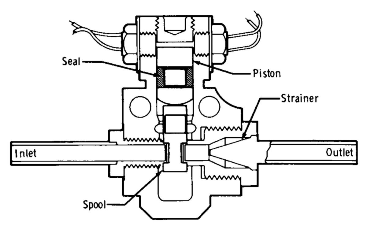 |
| Squib Valve |
The squib valve, whose piston occasionally failed to travel to the fully open position due to a piston seal design deficiency that allowed pyrotechnic blowby, was successfully redesigned. The inlet tube braze joint was also redesigned so that an external braze joint replaced the original internal one that could be more thoroughly inspected. All LM squib valves were eventually replaced with the new design.
Some quadruple check valves did not meet the 10 standard cubic centimeters/hr leakage specification. However, these leakage rates were determined to be acceptable for the LM missions because squib valves were reserved for helium-system isolation and only operated just before ascent-engine operation.
A production LM ascent-stage propellant tank that was tested for 47 hrs in a 105° F temperature-controlled environmental chamber while filled with oxidizer to 98% capacity and pressurized to 245 psi started losing pressure at the rate of 2.5 psi/min due to a 0.5" crack in the lower hemisphere membrane area. A metallurgical evaluation revealed stress corrosion that had resulted from an undesirable nitric acid content reduction in the N2O4 oxidizer. The problem was resolved by adding 0.45% to 0.95% nitric oxide to the oxidizer.
All-welded tank constructions were developed in which the heavy bolted flanged manhole closures at the tank bottoms and diffuser at the tank tops were eliminated, saving about 8 lb per tank. The zero-gravity cans and antivortex baffles were redesigned to use titanium rather than aluminum.
Original propellant feedlines incorporated flex hoses to absorb line movement; these hoses failed during design-verification testing. The flex hoses were replaced with a bellows assemblies and restraining bars, but ultimately ball joints replaced the bellows.
As LM design progressed it became overweight and a weight-saving program resulted in reducing the propellant-feedline wall thickness, which were installed on LM-6 and subsequent. Grumman started a qualification program on the thin-wall line and ball-joint assembly, but during vibration testing a leak developed at the bracket holding the line to a torus ring at the tank bottom. Grumman determined that stress concentrations in the bracket welds were at fault. Brackets on existing lines with wall thickness less than 0.049" were ground off, and if there were no cracks, a clamshell bracket and saddle were installed with epoxy. A new feedline without the weld was used for LM-10 and subsequent.
Test Articles and Test Rigs
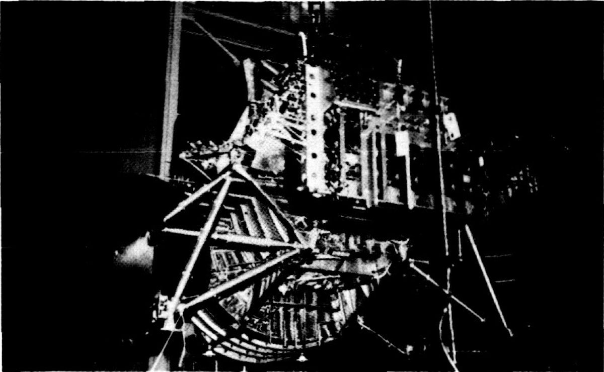 |
| Test Rig PA-1 |
Several test articles and test rigs were developed and tested to accomplish the required APS testing program. These included breadboard testing for early system design verification. Four heavyweight test rigs were built; these rigs were essentially open structures upon which the various propellant-feed-section components and the pressurization modules could be mounted in the same arrangement and relative locations as on the LM. The rigs were used for cold-flow testing at the Grumman facility, for early engine development at Bell, for helium-pressure-blowdown tests at the Grumman cold-flow facility, and for preproduction engine system testing.
System Checkout
During LM-1 and LM-3 functional checks relief-valve burst disks ruptured prematurely. Investigation revealed that the burst-disk design would not allow any backpressure on the disks without premature rupture. As a result of these failures, the checkout procedures were corrected in an attempt to preclude backpressure on other vehicles. In spite of the precautions taken, premature relief-valve burst disk rupture remained a checkout problem throughout the program.
Quadruple check-valve leakage was a common checkout problem, which required purging, valve replacement or wavers in most vehicles. Since valve replacement involved many debrazing and brazing operations that could introduce contamination, complete helium-module replacement was the preferred solution. Early vehicle checkout was plagued by failure and replacement of helium regulators, solenoid valves, relief valves, and the engine.
Flight Performance
The LM flight program consisted of one unmanned flight, LM-1. An unmanned flight was planned for LM-2 but was canceled and LM-2 was used as a ground-based test article. The first manned vehicle was LM-3, which demonstrated successful earth orbit operation. LM-4 was used in lunar-orbit operation tests, and LM-5 achieved the first lunar-landing.
LM-1 (Apollo 5)
LM-1 was the first flight-configuration lunar module mission, with objectives of verifying the APS and abort-staging in preparation for manned flight. A Bell engine with a Bell injector was installed. After the descent engine shutdown prematurely, the mission plan was altered to include two ascent-engine firings. The first was of 60 seconds duration. Approximately 1.5 hrs later, the engine was again fired to propellant depletion. The total ascent-engine firing time was about 40 seconds less than predicted. About 20 seconds was blamed on higher-than-expected RCS propellant usage through the propellant interconnect as a result of the control configuration after staging. Another 10 seconds was caused by propellant slosh. High vehicle-attitude rates caused the propellant-tank outlet ports to be uncovered prematurely. An oxidizer-depletion shutdown had been expected, but when propellant in the feedlines, sufficient for about 1 second of nominal operation, was depleted helium ingested into the oxidizer and the fuel lines caused thrust decay. Engineers reckoned that an additional 10 seconds of normally usable propellant was in the tanks at thrust decay, but was unavailable because of sloshing and high vehicle roll rates.
The start transient and early steady-state operation showed high-amplitude chamber-pressure oscillations on both the first and the second engine starts. The 400-Hz oscillations, which occurred immediately after the start-transient overshoot, were characteristic of the Bell engine during ground-based testing and were expected on this flight. The oscillations appeared to be a form of low-frequency instability, caused by the coupling of the combustion process with the propellant-feed system resonant frequency, which was exacerbated by gaseous helium, dissolved or entrained in the fuel, also inducing coupled instability. The high-magnitude 400-Hz oscillations resumed approximately 4.5 seconds before thrust decay, an indication of propellant gas entrainment caused by the vortexing or sloshing resulting from high vehicle-attitude rates. The thrust decay appeared smooth; no spikes or other detrimental effects were apparent after the 400-Hz oscillations damped out.
The engine propellant valves should have closed immediately after fuel depletion because the valves were fuel-actuated. However, the valve-position indicators showed that the valves did not start to close until 85 seconds after the thrust decay onset and were not closed completely when the telemetry signal was lost by the ground station 58 seconds later. System pressures and temperatures suggested that some fluid flow blockage occurred between the propellant tanks and the engine after the initial thrust decay, likely caused by small amounts of propellant frozen by cold helium ingested into the feedlines. Although not a normal depletion shutdown, no hazardous or detrimental effects were apparent.
Ascent engine performance was not directly verified within the expected accuracy because flow-rate measurement was lost and because of the high vehicle roll rates during propellant depletion; however, the engine-pressure measurements and the vehicle velocities that were obtained indicated that the ascent-engine performance was within the nominal predicted tolerances.
LM-3 (Apollo 9)
The LM-3 mission included the first manned LM flight test. The mission was also the second manned Saturn V launch vehicle flight test and the third manned Block II CSM flight. The overall mission objective was to qualify the combined CSM/LM for lunar flight by evaluating crew operation of the separated LM and demonstrating docked-vehicle functions in earth orbit. LM operations included an ascent engine firing to propellant depletion after final separation from the CSM.
The APS was fired twice, once for three seconds firing while the ascent stage was manned and once to propellant depletion after the crew departed. The LM was out of ground-tracking-station range during the first ascent-engine firing, so no data were immediately available. However, when data were first acquired after the firing, system pressures and temperatures were nominal. The second ascent-engine firing lasted for 362.3 seconds. During the second firing, system pressures were lower than expected for the first 290 seconds, indicating a primary regulator malfunction. The lower pressures produced no undesirable effects. The second ascent-engine firing was terminated by the planned oxidizer depletion. The engine was commanded off approximately 10 seconds later. The depletion shutdown appeared nominal in all respects. The transient characteristics that the engine demonstrated during the oxidizer-depletion shutdown mode were investigated and were found to compare favorably with ground-based test data. All applicable transient-specification requirements were met.
A detailed assessment was made of the lower-than-expected system pressures to determine the cause and magnitude of the malfunction. After extensive testing in the thermo-chemical test area at the Manned Spacecraft Center and on test rig PA-4 at the WSTF, it was concluded that the most probable cause was regulator contamination during a solenoid-valve replacement. A review of regulator backflow and system repair procedures during LM checkout indicated the possibility of minor backflow on vehicles through LM-7. Cautions were added to the change out procedures, and special instructions were given to personnel. Increased surveillance of regulator checkout data was maintained by the subsystem office for all subsequent vehicles.
LM-4 (Apollo 10)
The LM-4 mission was the first LM flight test in a lunar environment and the second manned LM flight. Because the mission objective was to show a fire-to-depletion firing and not a ΔV, the amount of propellant loaded was approximately 50% of the nominal lunar mission. The mission objective was to duplicate a lunar landing mission, with the exception of lunar landing and lift-off. Inherent in this objective was the performance of the APS during the lunar-orbit-insertion maneuver. Also included as mission objectives were verifications of LM operation in a lunar environment and of mission support of all spacecraft at lunar distances.
Docking of the CSM with the LM and separation of the docked vehicles from the Saturn IV-B occurred 4 hours after launch. Undocking of the LM from the CSM in lunar orbit occurred 98.5 hours after launch. Approximately 2 hours after completion of the descent propulsion system firing, the descent stage was separated and the APS engine was fired for 15.6 seconds. Upon completion of this insertion maneuver, the ascent stage was docked with the CSM, equipment and crew were transferred from the ascent stage. Approximately 6 hours later, the ascent stage was separated, and the engine was ignited for the 248.9- second burn to propellant depletion.
Shortly after the first APS burn ignition signal, the ascent-engine-quantity caution light came on, triggering a master caution and warning alarm. The ascent-engine-quantity caution light was controlled by the oxidizer and fuel low-level sensors in the propellant tanks. Approximately 1 second after the ascent engine ON signal for the manned LM-4 APS burn, the oxidizer low-level sensor activated for about 1 second while the master alarm was on for 2 seconds before being manually reset. Low-level sensors in both oxidizer and fuel tanks operated as expected during the remainder of the first burn and the entire second burn. Based on this performance, it was concluded that the signal received during the first burn was valid.
Engineers believed the anomaly was caused by insufficient settling of APS propellants before the burn. The LM-4 propellant tanks were filled to 50%, the least on any flown vehicle. Based on information contained in the Spacecraft Operation Data Book, an RCS ullage-propellant settling maneuver of 3 - 4 seconds would be adequate for a LM-4's propellant load. The actual RCS ullage-propellant-settling maneuver before APS first-burn ignition lasted for 4.1 seconds. The propellant-settling maneuver was reexamined, and the settling maneuver duration extended for increased ullage (decreased propellant) volume.
LM-5 (Apollo 11)
The LM-5 mission was the third manned LM flight, the fifth manned Block II CSM flight, and the fourth manned Saturn V flight. The mission objective was to perform the first manned lunar landing and return. Burn time for the APS lunar lift-off maneuver was 434.9 seconds. Upon completion of the insertion maneuver, the ascent stage docked with the CSM, and the crew and equipment transferred. Approximately 3.5 hours later, the ascent stage was jettisoned. APS performance was nominal.
Conclusion
References
Apollo Operations Handbook, Block II Spacecraft, Volume 1: Spacecraft Description 5M2A-03-BLOCK II (Houston, Texas: Manned Spacecraft Center, 15 Oct 1969).
Brooks, Courtney G., James M. Grimwood, Loyd S. Swenson, Jr. Chariots for Apollo: A History of Manned Lunar Spacecraft NASA SP-4205 (Washington, DC: NASA, 1979).
Cherne, Jack M. Mechanical Design of the Lunar Module Descent Engine (Redondo Beach, California: TRW Systems, 1967).
Dressler, Gordon A., J. Martin Bauer TRW Pintle Engine Heritage and Performance Characteristics (Redondo Beach, California: TRW Inc., 2000
Fisher, Steven C. and Shamin A. Rahman, eds. Remembering the Giants: Apollo Rocket Propulsion Development (Washington, DC: NASA, 2009).
Hoagland, Richard. Apollo News Reference (Bethpage, New York: Public Affairs, Space, Grumman Aerospace Corporation, 1971).
Humphries, Clarence E. and Reuben E. Taylor Apollo Experience Report — Ascent Propulsion System TN D-7082 (Houston, Texas: NASA Manned Spacecraft Center Mar 1973).
Hammock Jr., William R., Eldon C. Currie and and Arlie E. Fisher. Apollo Experience Report — Descent Propulsion System TN D-7143 (Houston, Texas: NASA Manned Spacecraft Center, Mar 1973).
Interbartolo, Michael Apollo Lunar Module Propulsion Systems Overview JSC-17237-14 (Houston, Texas: NASA Johnson Space Center, 1 Jan 2009).
Lunar Module LM-10 through LM-14 Vehicle Familiarization Manual LMA790-2 (Bethpage, New York: Grumman, 1 Nov 1969).
Vaughan, Chester A., Robert Villemarette, Witalij Karakulko, Donald R. Blevins Apollo Experience Report — Lunar Module Reaction Control System TN D-6740 (Houston, Texas: Manned Spacecraft Center, Mar 1972).
--- On to Part 9.44, The Apollo Lunar Module Ascent Engine ---
Send mail to
![]() with questions or comments about this web site.
with questions or comments about this web site.
![]()