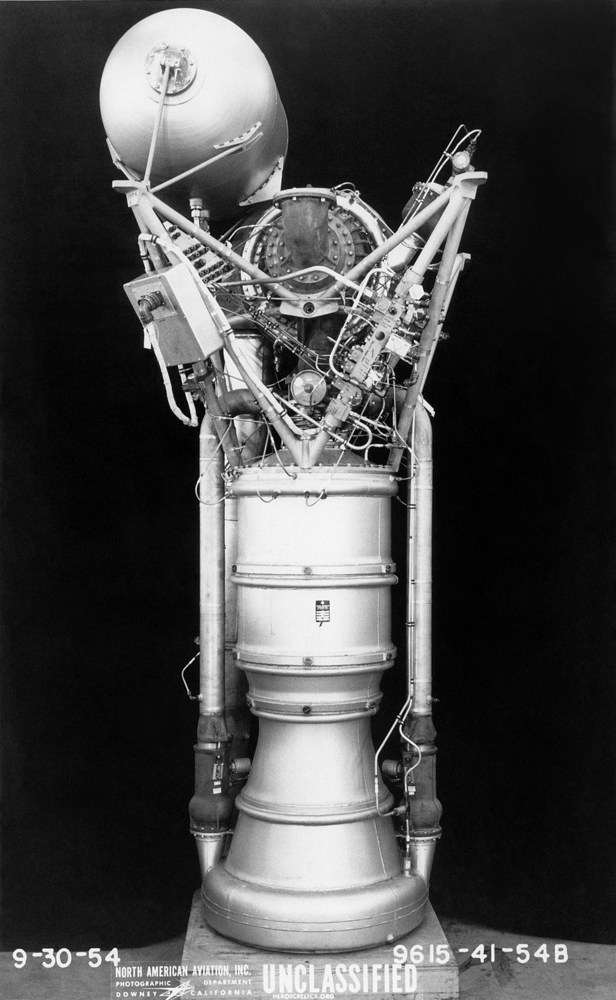
NAA 75-110-A-7,
a Redstone Engine
U.S. Manned Rocket Propulsion Evolution
Part 4.2: The Redstone Engine
Compiled by Kimble D. McCutcheon
Published 7 Dec 2020; Revised 13 Mar 2026
NAA 75-110-A-7, a Redstone Engine |
After a period of examining and experimenting with captured V-2 rockets, U.S. engineers, sometimes in conjunction with the German engineers and scientists who had immigrated to the U.S., began working on designs of their own. North American Aviation (NAA) developed the XLR-43-NA-1, a LOX/alcohol engine based on V-2 technology for its Navaho cruise missile project. This engine had half the mass and a third more thrust than the V-2 engine; at the end of development its thrust would be nearly double that of the V-2. The complex and costly V-2 combustion chamber, with its 18 burner cups, spherical shape, and LOX plumbing maze, was replaced by a flat plate injector and cylindrical combustion chamber. A straight-sided 15° divergent nozzle section was retained. Similar to earlier V-2s, the XLR-43-NA-1 had a turbopump driven by high-pressure steam generated by catalyzing hydrogen peroxide with potassium permanganate in a steam generator. When the Ordnance Guided Missile Center (OGMC) at Redstone Arsenal, Alabama began designing the Redstone missile, it turned to NAA to enhance its XLR-43-NA-1, producing the NAA (Rocketdyne) 75-110 engine series. The designation indicates the engine could produce 75,000 lbT for 110 seconds. |
 |
 |
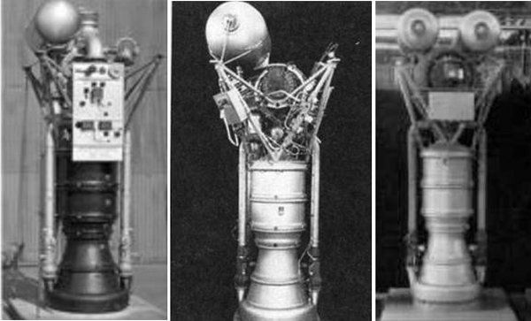
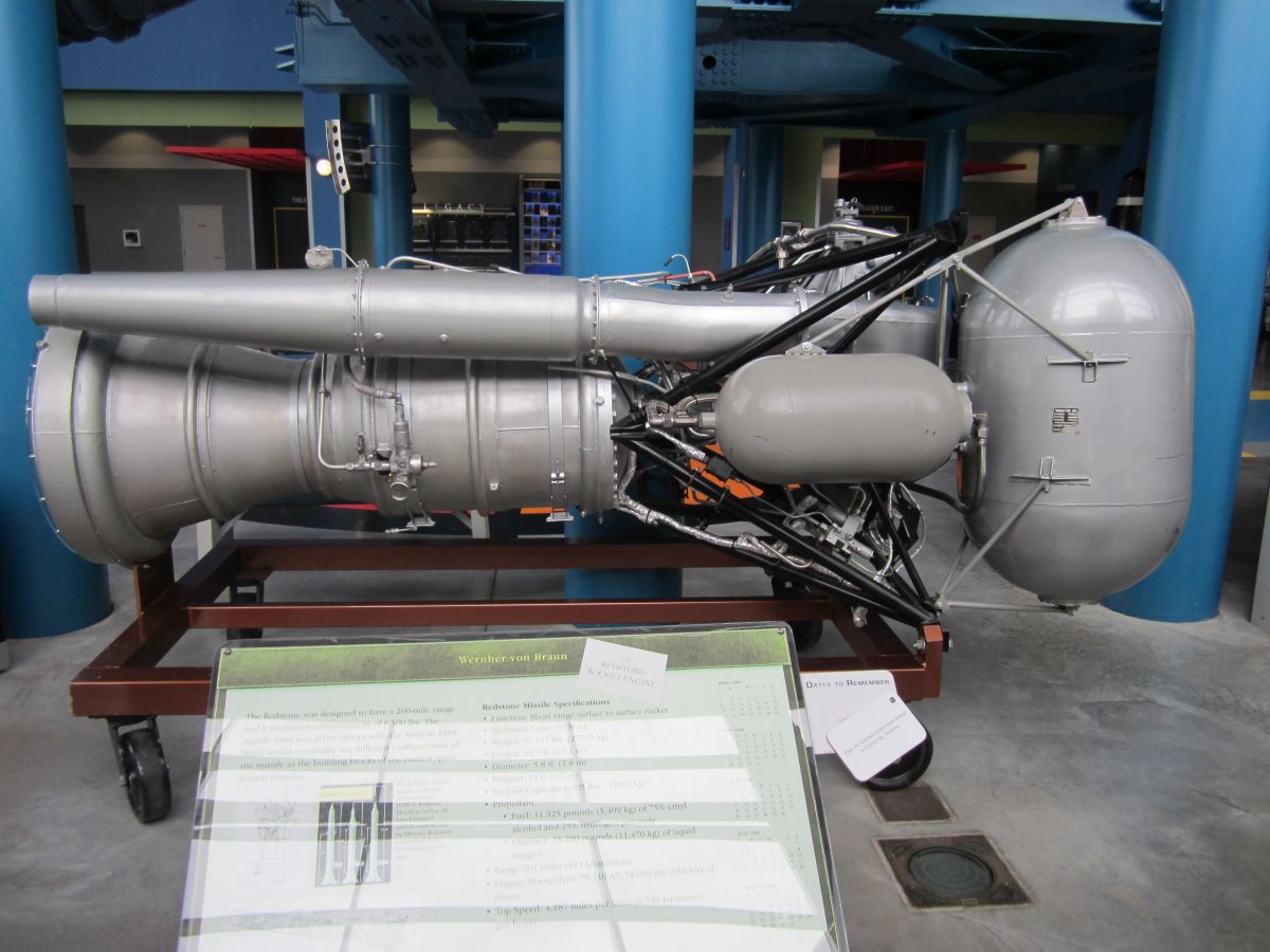
| The North American Aviation XLR-43-NA-1 (NASA) | The Rocketdyne 75-110-A-7 |
When the Redstone development team, led by V-2 rocket scientist Wernher von Braun, needed an engine capable of 75,000 lbT, Rocketdyne was asked to modify the XLR-43-NA-1 to meet the new requirements. The new engine was designated NAA 75-110, and the first one was ready for shipment to Redstone Arsenal by the end of July 1953.
| Component | A-1 Engine | A-7 Engine |
|---|---|---|
| Regulators | 4 | 1 |
| Relief Valves | 2 | 1 |
| Solenoid Valves | 12 | 4 |
| Pressure Switches | 6 | 2 |
| Check Valves | 3 | 0 |
| Test Connections | 4 | 1 |
| Pneumatic Filter | 0 | 1 |
| Total | 31 | 10 |
The A-6 and A-7 variants became Redstone missile production engines.
 |
 |
 |
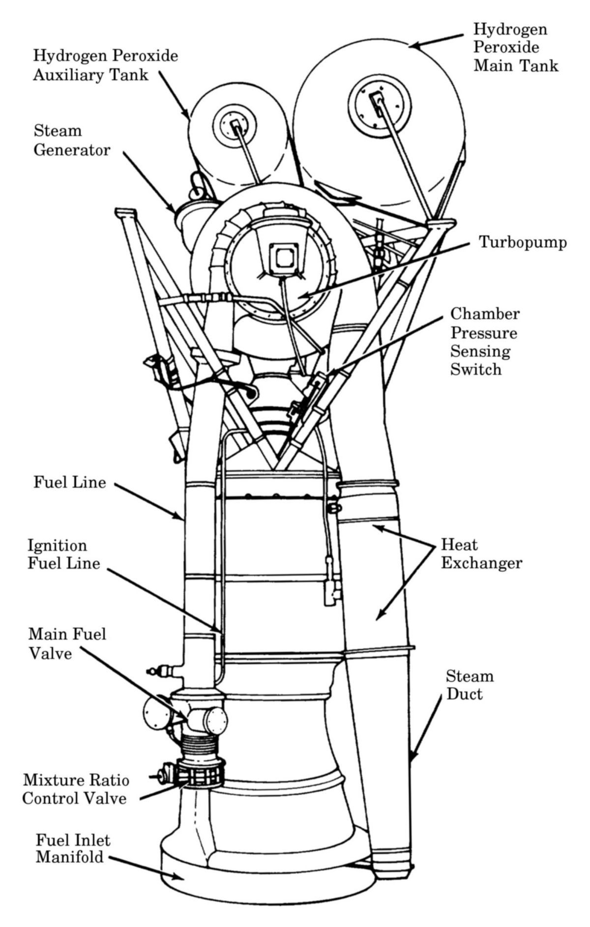
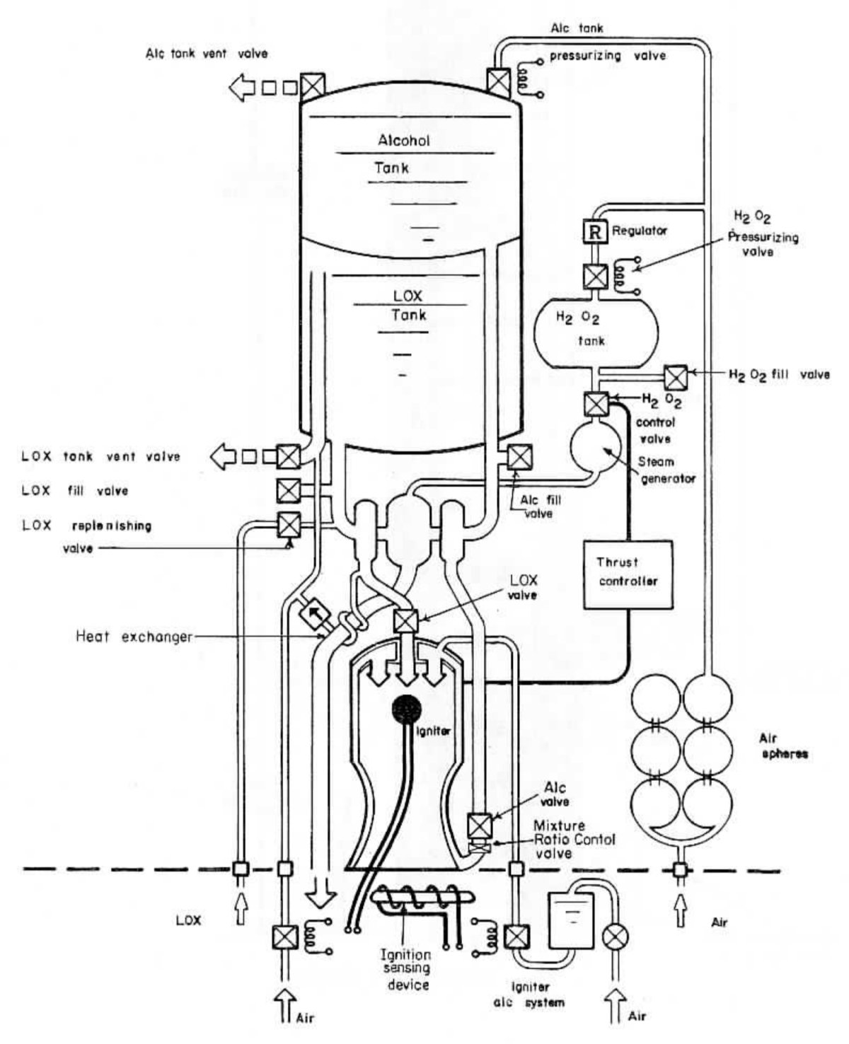
| Redstone Thrust Unit (US Army) | Redstone Propulsion System Functional Schematic (US Army) Note that ignition fuel is supplied by ground support equipment. |
Redstone Propellent and Hydrogen Peroxide Flow (US Army) |
 |
 |
 |
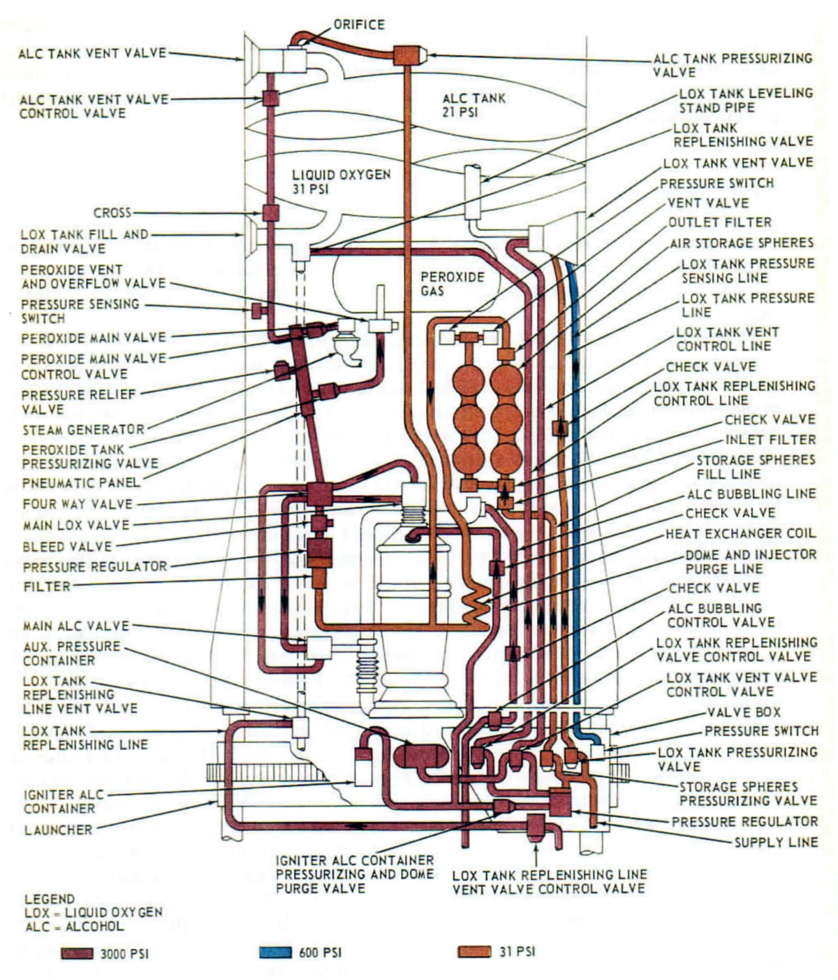
| Redstone Pneumatic System (US Army) Note all the ground support systems. |
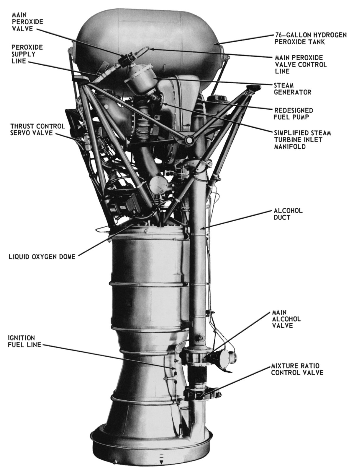
The NAA (Rocketdyne) 75-110-A-6 had two fuel supply lines. (heriocrelics.org) |
The NAA (Rocketdyne) 75-110-A-7 had one fuel supply line. (heriocrelics.org) |
 |
 |
 |
.jpg) |
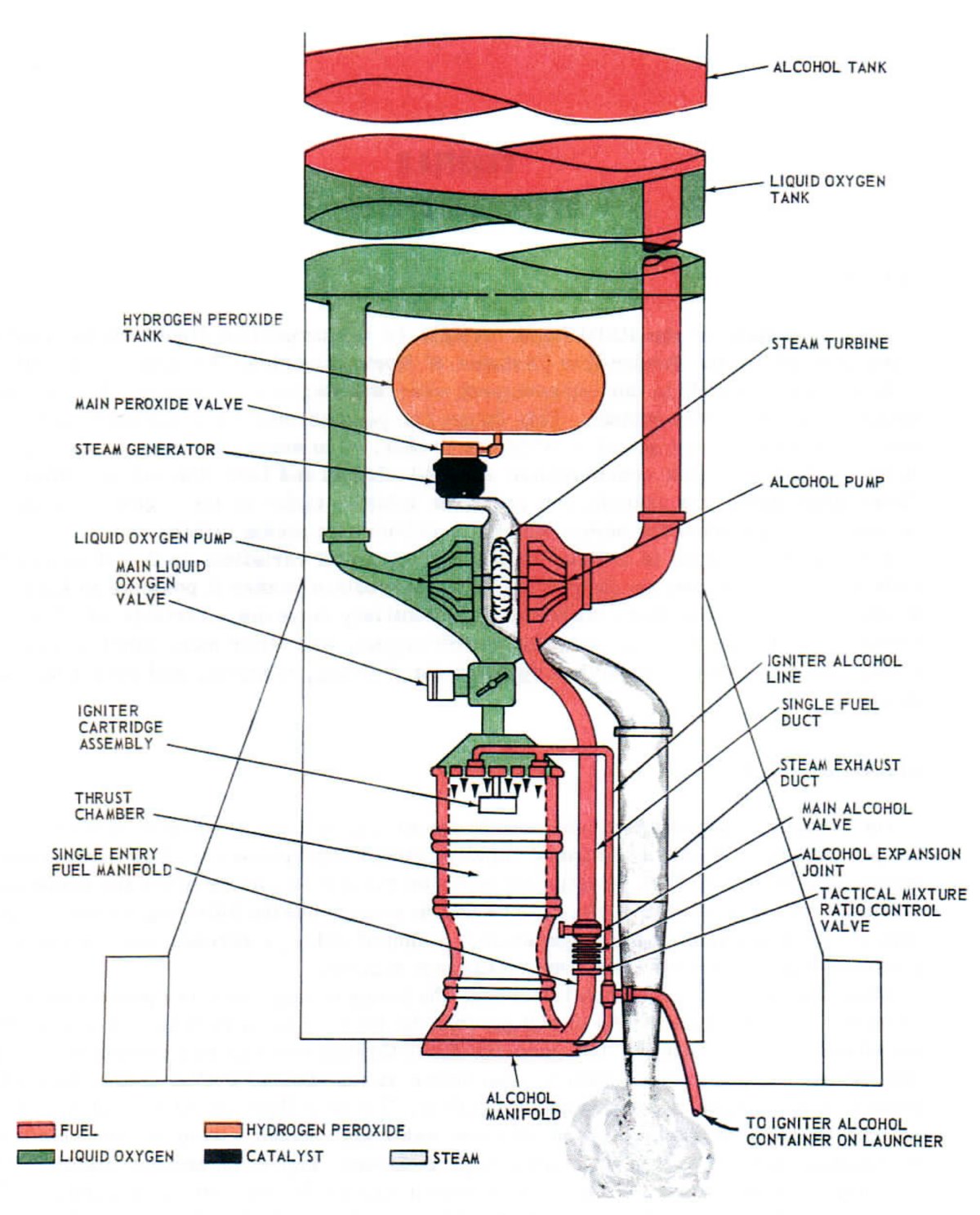
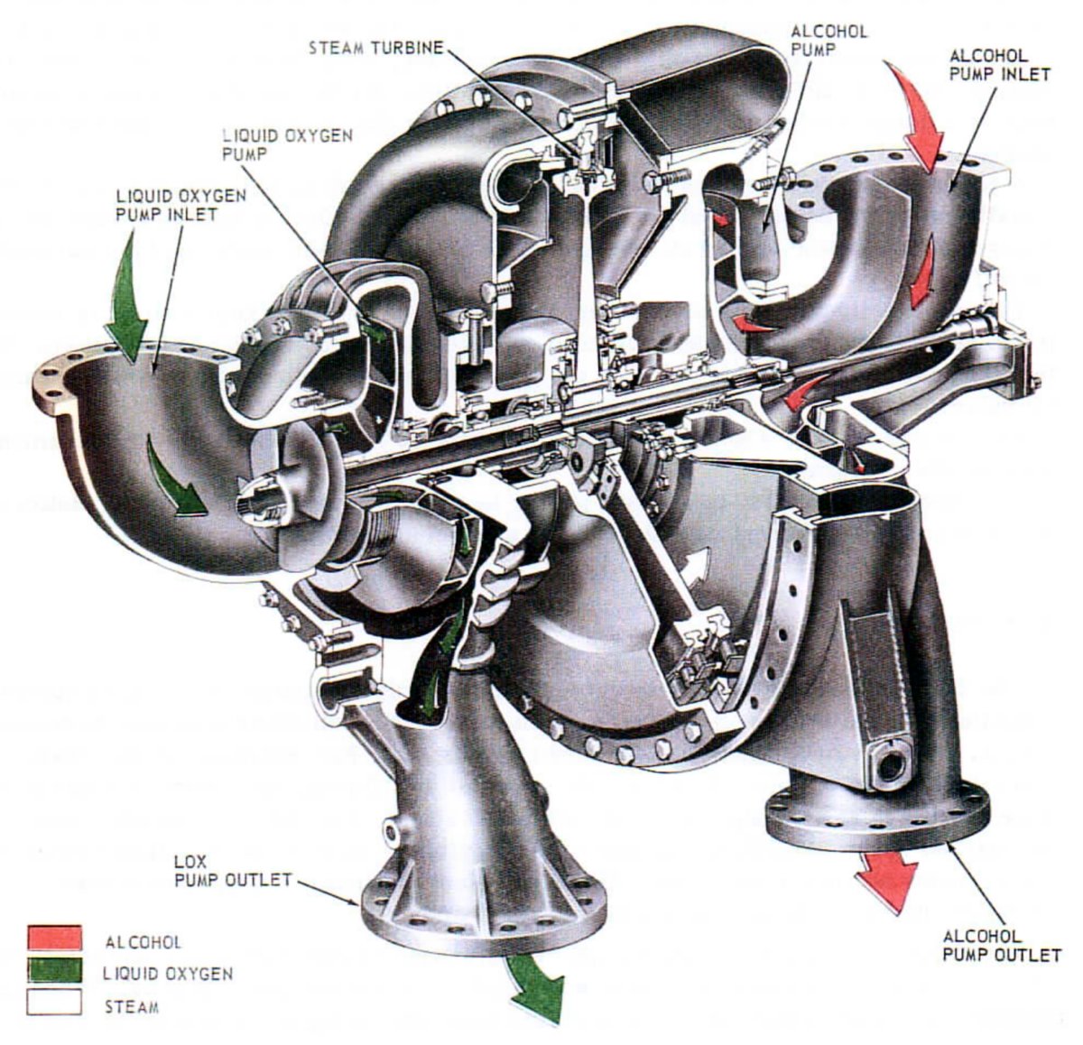
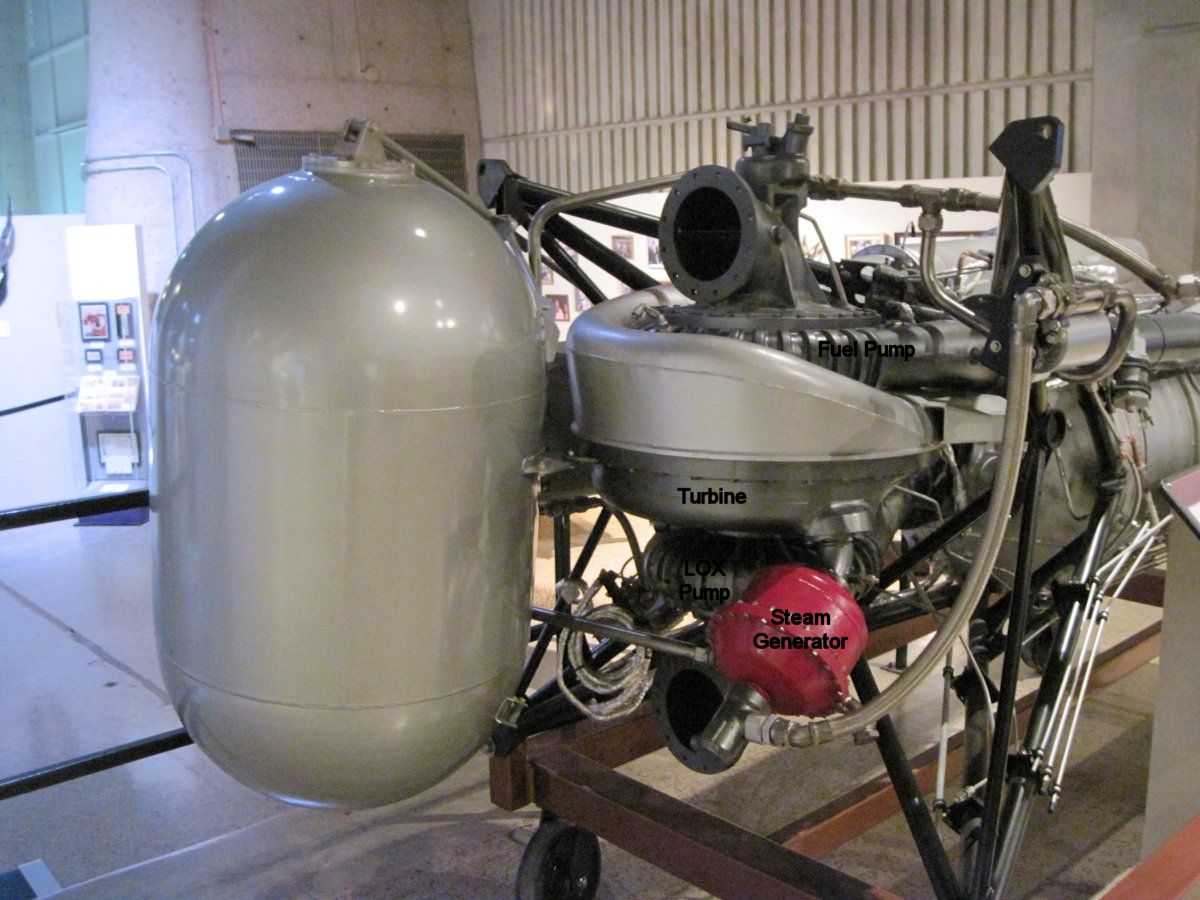
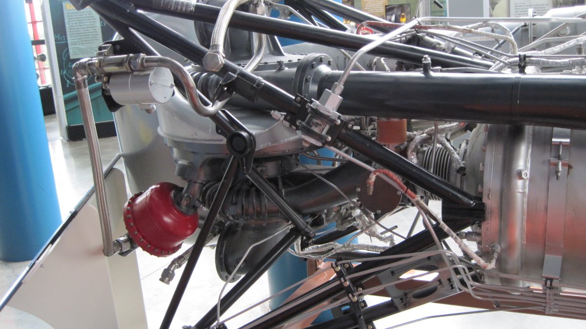
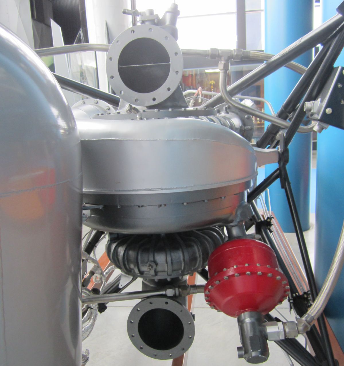
| NAA (Rocketdyne) 75-110-A-7 Turbopump (US Army) |
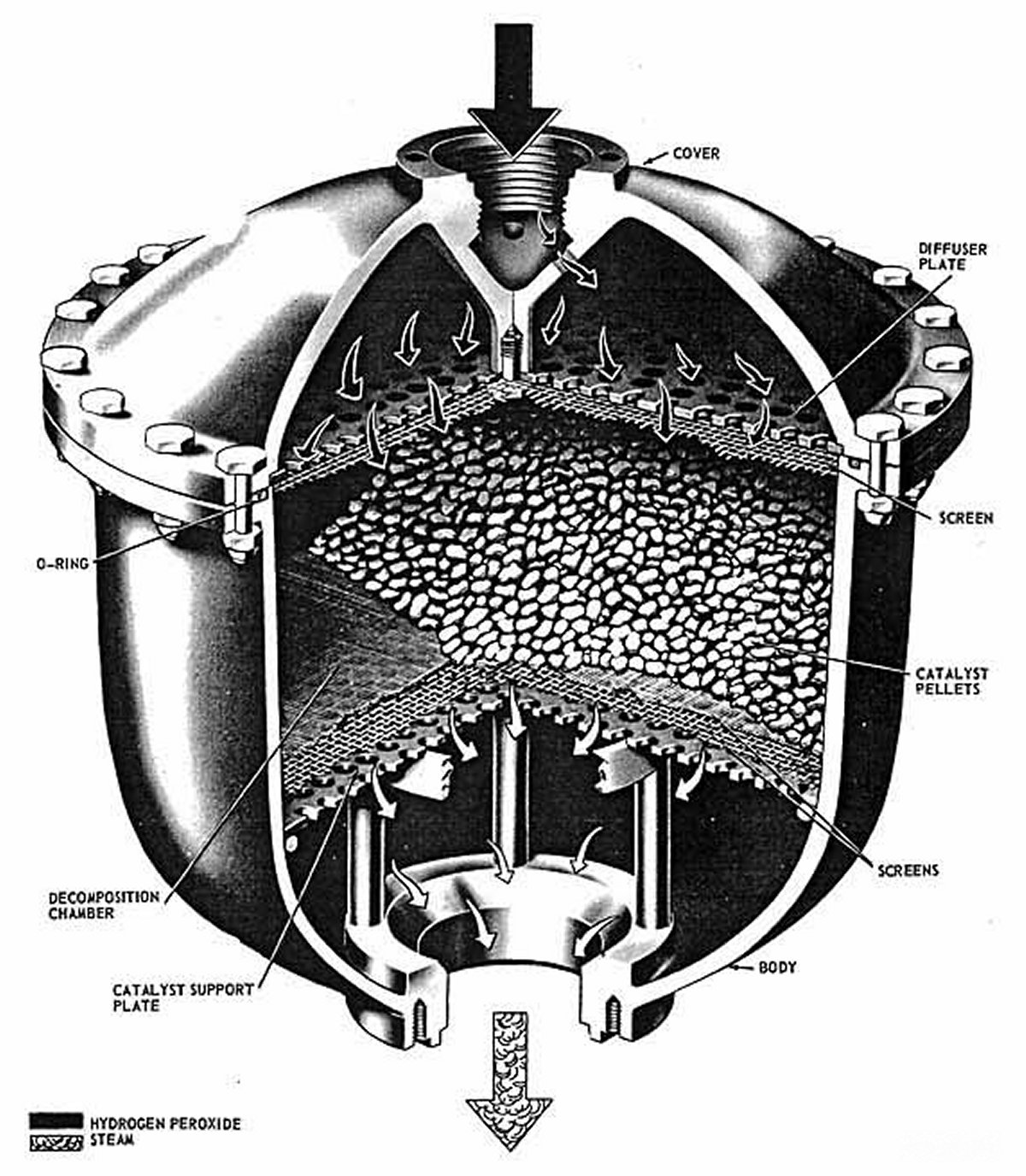
NAA (Rocketdyne) 75-110-A-7 Steam Generator (US Army) |
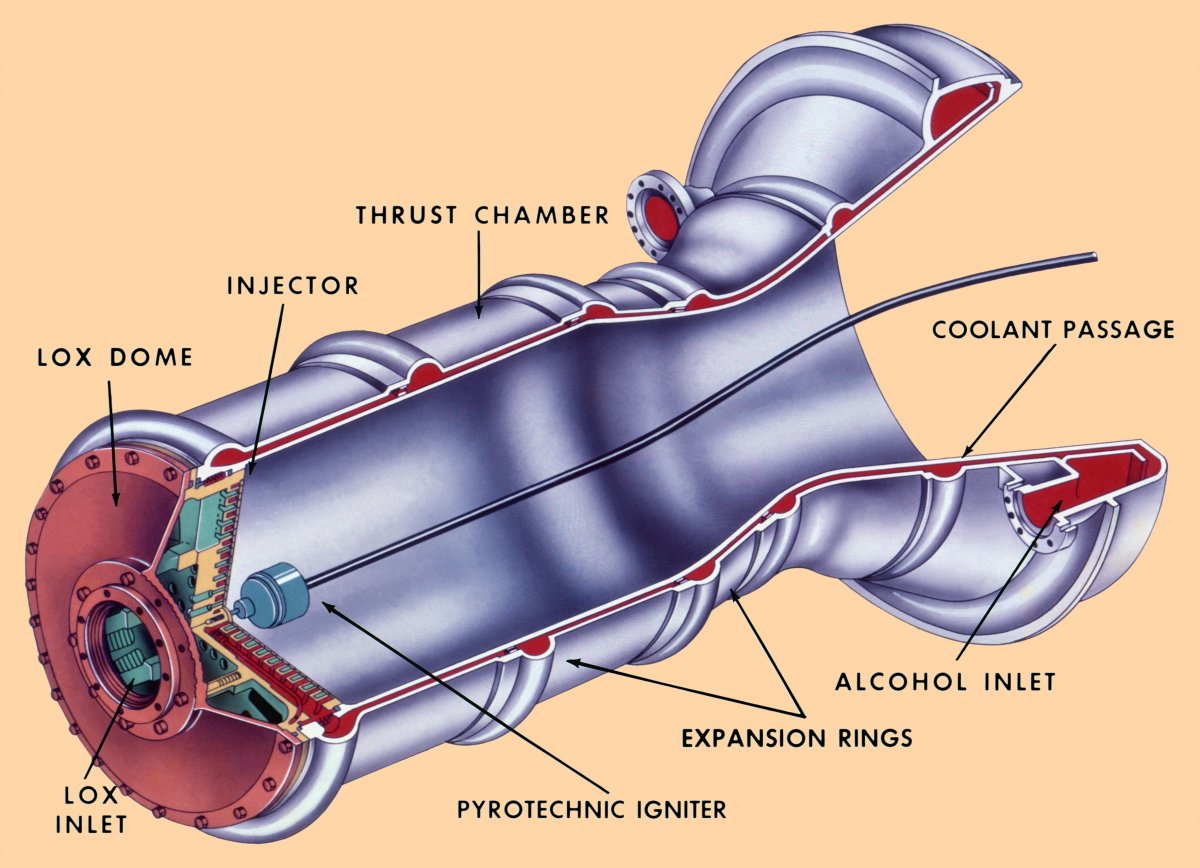
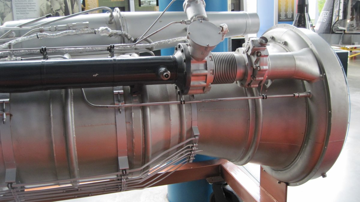
NAA (Rocketdyne) 75-110-A-6 Thrust Chamber (heriocrelics.org) |
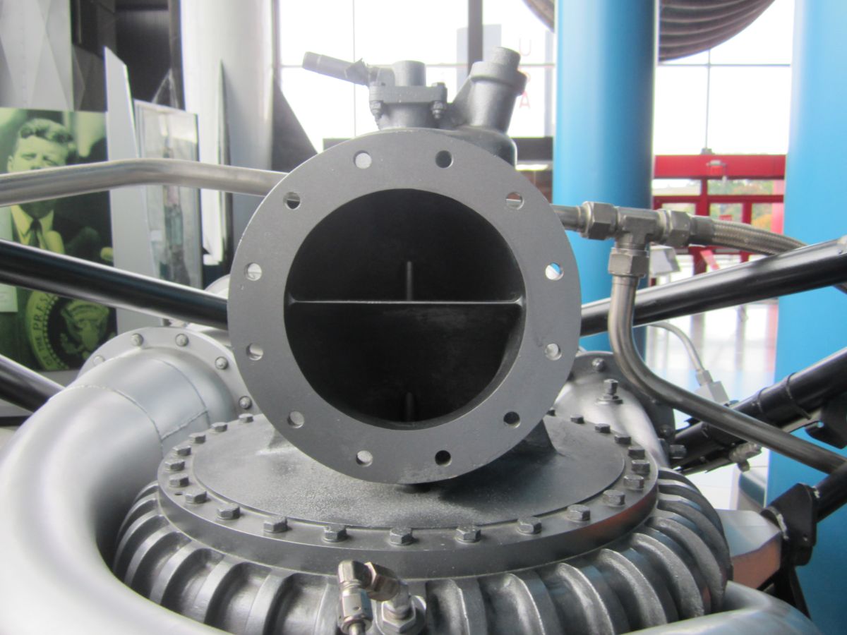
NAA (Rocketdyne) 75-110 Flat Plate Injector The inner ring carries starting alcohol from ground support equipment. Tiny holes in the outermost ring bleed alcohol to shield the combustion chamber and nozzle inner liner from the heat of combustion. (heriocrelics.org) |
Component Details
 |
 |
 |
 |
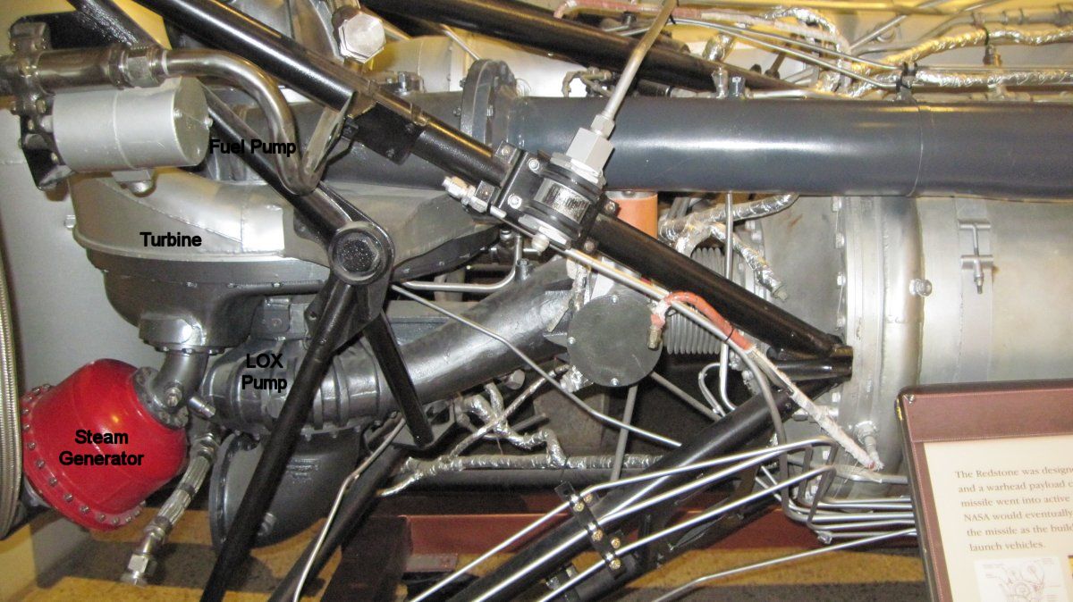 |
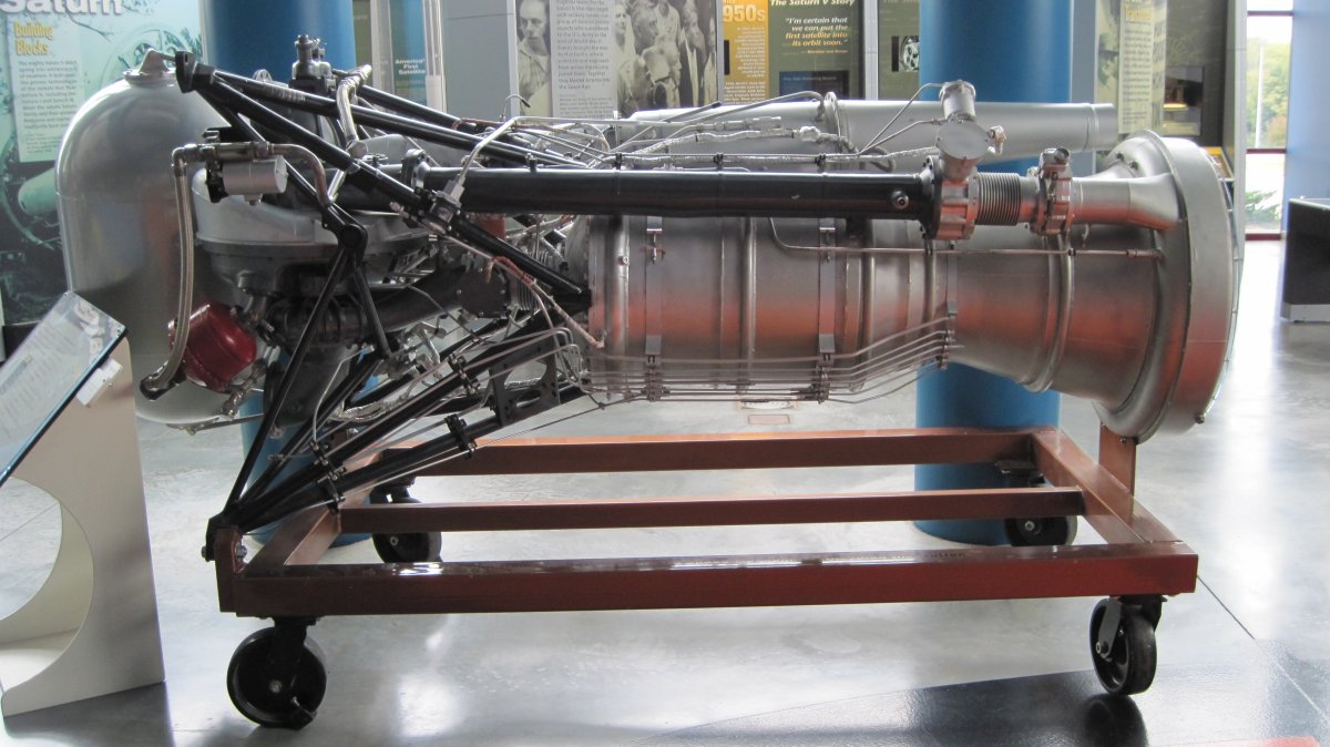
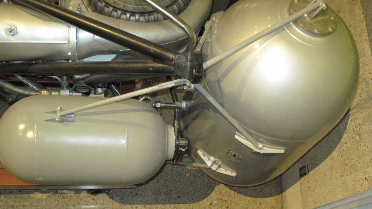
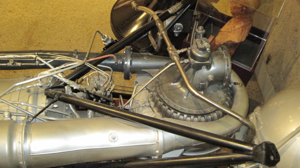
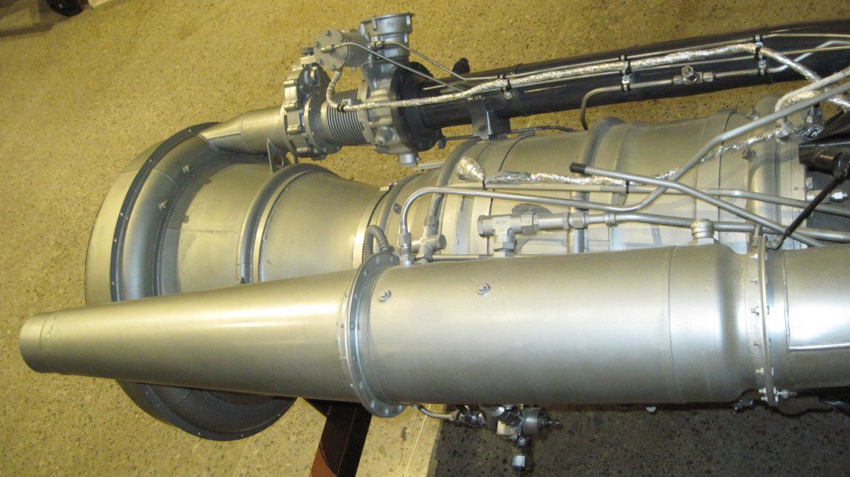
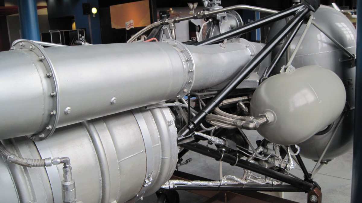
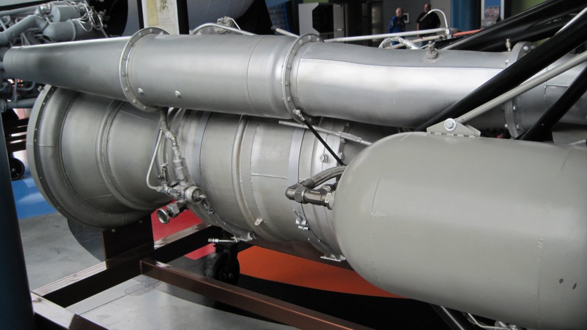
| Main Peroxide Tank, Turbopump and Steam Generator (Red) | Main and Auxiliary Peroxide Tanks | Alcohol Pump and Heat Exchanger | Steam Exhaust Duct | Fuel Pump (Top), Turbine (Center), and LOX Pump (Bottom) |
 |
 |
 |
 |
 |
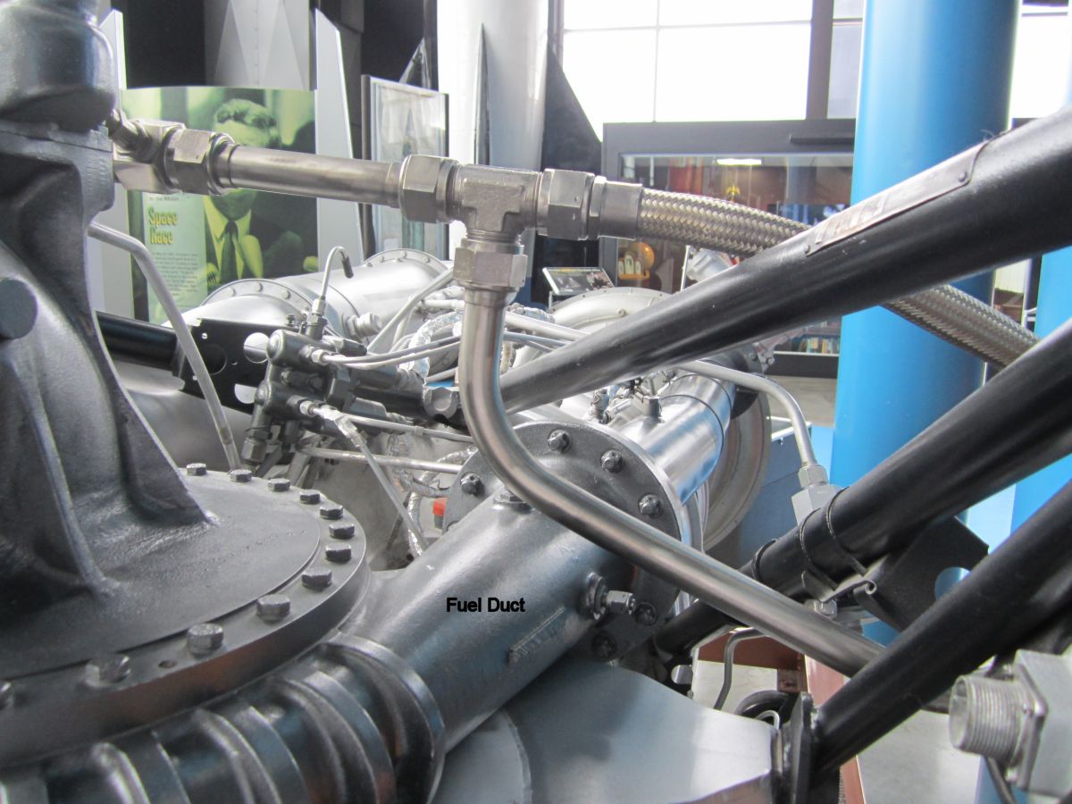
| Side View of Engine Steam Side | View of Engine Steam Side Looking Toward the Top | View of Engine Steam Side Looking Toward the Bottom | View of Engine Fuel Duct Side Looking Toward the Bottom | View of Engine Fuel Duct Side Looking Toward the Bottom |
 |
 |
 |
 |
 |
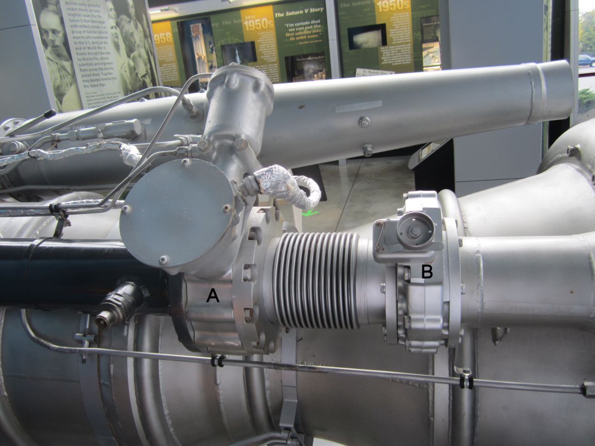
| Turbopump Assembly | Fuel Pump Inlet | Fuel Pump Outlet | Main Fuel Valve (A) and Mixture Ratio Control Valve (B) |
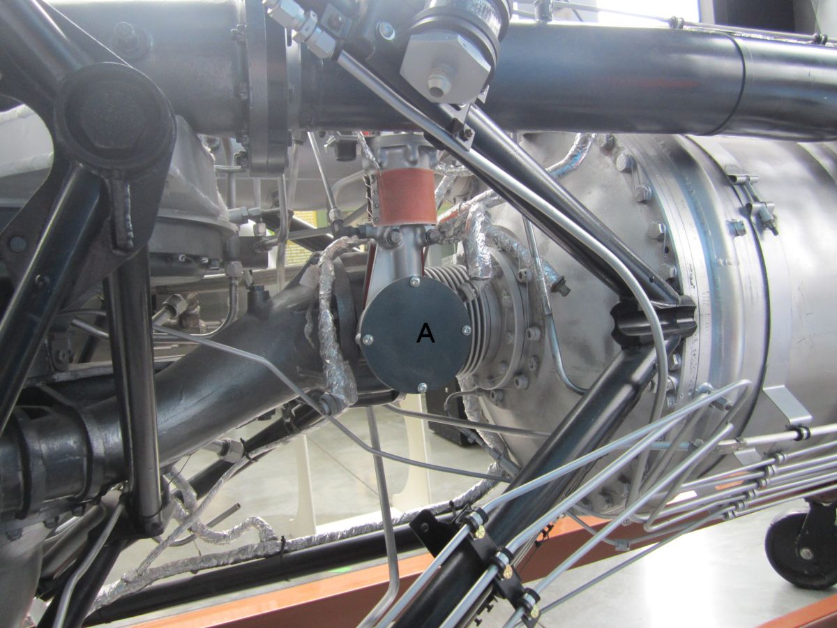
Main LOX Valve (A) |
Redstone Firing Procedure
After the missile was tested, erected, and optically aligned to the True Line of Fire (TLOF, that line over the ground that connects the missile launcher to the target), the final firing preparations were begun. Some of the fueling preparations can be started as soon as the missile was erected. This activity included the connection of various alcohol and LOX lines and valves and the positioning of the fueling ladder. The fire-fighting equipment was in the area during propellant loading operations. The engine cooling jacket was filled with water if the ambient temperature was above 35°F, or lithium chloride if colder, from a container on the alcohol trailer; this permitted a smooth transitional flow of alcohol during engine start. The mixture ratio control valve was also adjusted to compensate for changes in fuel density based on its temperature.
The alcohol trailer was positioned approximately 20 feet from the fueling ladder. The 3.5 quart igniter alcohol container, located in the launcher, was filed by gravity flow from the alcohol trailer emergency valve. The alcohol trailer was connected, through the fueling ladder, to the missile alcohol tank, and the alcohol was pumped into the tank. When the missile alcohol tank was full, the alcohol trailer was disconnected and driven out of the immediate launch area.
LOX Filling was accomplished from two LOX trailers that were simultaneously connected, through a "Y" connection, to the fueling ladder and then to the missile LOX tank. LOX pumping was started from one of the LOX trailers. After a delay of three or four minutes, the pumping of the second LOX trailer (replenishing trailer) was started. This delay was to assure that the depletion of LOX in the second trailer will be less than that of the first, after LOX filling was completed. When the missile LOX tank was full, the LOX pumping operation was stopped and the first LOX trailer was disconnected and driven out of the immediate launching area. The second LOX trailer (the replenishing trailer) was disconnected and moved away from the launcher to a distance of approximately 150 feet. A LOX replenishing line was then connected from the replenishing trailer to the replenishing arm, mounted on the launcher and connected to the missile LOX tank. Periodically, throughout the rest of the operation until missile firing, the normal LOX boiloff from the missile LOX tank will be replaced by the operator of the remote firing box via a replenishing switch.
A hydrogen peroxide truck was positioned near the missile, and the container was connected to the missile hydrogen peroxide tank. The hydrogen peroxide was then pumped into the missile's tank. Upon completion of the hydrogen peroxide filling, the hydrogen peroxide truck was disconnected and driven from the immediate area.
A final vertical range computer check was performed, along with operational status checks of the range guidance computer and the cutoff computer. Upon verification of the in-tolerance operation of the range computer, the presetting information listed on the firing mission data sheet was installed into the cutoff computer. This presetting information included constant values of velocity and displacement, which were compensation for inherent errors peculiar to the individual trajectory of the missile.
A final check of the vertical lateral computer was performed, followed by a warhead prelaunch check, which verified network circuits related to the warhead. The type of warhead burst (air or surface) was also selected at this time.
The guided missile test station was disconnected from the missile system and driven out of the firing area. The powerplant ignition system was readied and the blind plugs, which serve as deactivating or safety devices, were installed. A final check of the missile TLOF was conducted. The immediate firing area was cleared of extraneous equipment and personnel.
The remote firing box operator activated the LOX replenishing switch until LOX tank overflow was visible. At the predetermined time and on order from the Firing Battery Commander, the remote firing box operator closed the firing switch.
| Engine | Model 39 | Rocketdyne 75-110-A-7 |
|---|---|---|
| Used In | German V-2 | Redstone |
| Era | 1943 | 1953 |
| Thrust, SL (lb) | 55,000 | 82,977 |
| Thrust, Vac (lb) | ? | 93,565 |
| Burn Time (sec) | 60 | 155 |
| Chamber Pressure (psi) | 218 – 239 | 318 |
| Specific Impulse (sec) | 203 – 239 | 235 – 265 |
| Propellant Flow (gps) | 33.5 | 41.3 |
| Propellant Flow (lb/sec) | 286 | 355 |
| Nozzle Expansion Ratio | 2.83 | 3.61 |
| Engine Weight (lb) | 2,484 | 1.479 |
| Thrust / Weight, SL | 22 | 56 |
| Fuel | 75% Ethanol | >75% Ethanol |
| Oxidizer | LOX | LOX |
| Mixture Ratio (Ox/Fuel) | 1.13 | 1.324 |
| Turbopump Output (hp) | 580 | 758 |
| Turbine RPM | 3,800 | 4,718 |
--- On To Part 5 ---
Send mail to
![]() with questions or comments about this web site.
with questions or comments about this web site.
![]()