Apollo Guidance and Navigation System
U.S. Manned Rocket Propulsion Evolution
Part 9.21: Apollo Command Module Guidance, Navigation and Control
Compiled by Kimble D. McCutcheon
Published 1 Dec 2022; Revised 8 Jan 2023
Apollo Guidance and Navigation System |
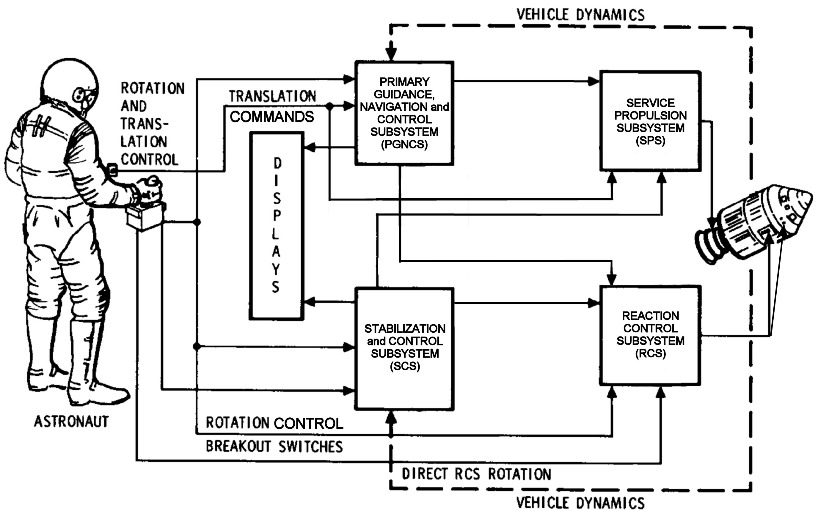
The Apollo spacecraft was guided and controlled by a primary guidance and navigation subsystem (PGNCS) working in conjunction with a stabilization control subsystem (SCS). The PGNCS was based on a gyro-stabilized platform that included accelerometers and could provide attitude and delta-velocity (ΔV) information, while the SCS, which had frame-mounted gyros, could only provide attitude rate-of-change information. Collectively, these subsystems provided rotational, line-off-flight, and rate-of-speed information that was interpreted and integrated by the Command Module Computer (CMC), which generated spacecraft propulsion subsystem commands. |
1.0 Overview
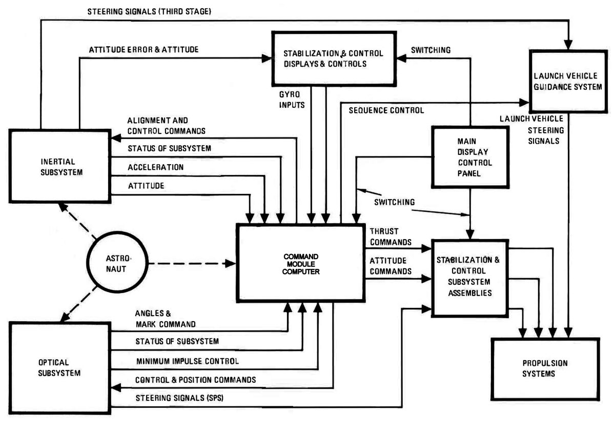
Three major subsystems – inertial, optical, and CMC – comprised the PGNCS. The inertial subsystem sensed velocity and spacecraft angle changes, and relayed this information to the CMC, which processed the information and transmitted any necessary signals to the spacecraft thrusters and engines. Astronauts used the optical subsystem to sight celestial bodies and earth/moon landmarks. The optical subsystem passed this information to the CMC for guidance and control purposes. The CMC used information from multiple sources to determine the spacecraft's position and speed. In automatic operation it originated guidance and control commands.
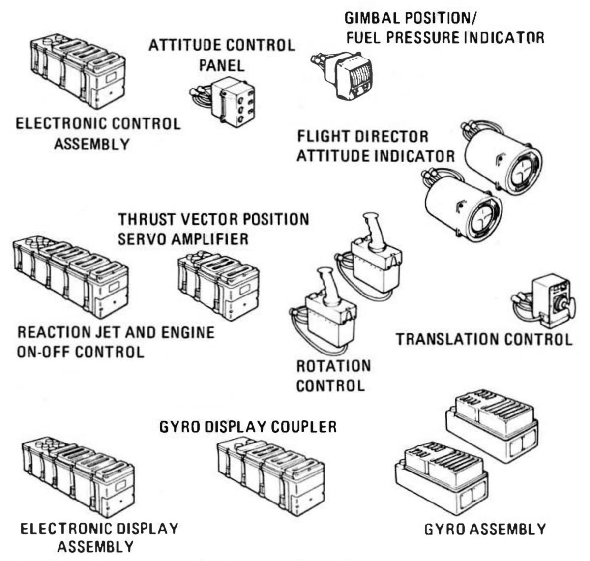 |
| SCS Components |
2.0 Stabilization and Control Subsystem
The SCS, produced by Honeywell, Inc., Minneapolis, Minnesota, determined (and optionally maintained) the spacecraft's attitude by controlling the service module RCS thrusters and SPE thrust vector, and during atmospheric entry, by the command module RCS thrusters. These subsystems were used to automatically and electronically control the spacecraft. The SCS was operated either automatically or manually, and all subsystem control functions were PGNCS backups.
Service propulsion engine (SPE) firings established the Apollo spacecraft trajectory. The speed, altitude, and flight path angle at the instant the last booster engine cut off determined the spacecraft's orbit characteristics – its apogee (maximum altitude), perigee (minimum altitude), velocity and position at any point, and the time to complete an orbit. Spacecraft engine firings were used to modify the trajectory established by the launch vehicle. An SPE firing duration, in conjunction with spacecraft's attitude, caused a change in the orbit's shape about the earth, tilted the orbital plane, or slowed it to permit atmospheric entry and return to earth. Even a flight to the moon is in actuality a very extended earth orbit.
2.1 SCS Equipment
 |
| Attitude Reference Equipment |
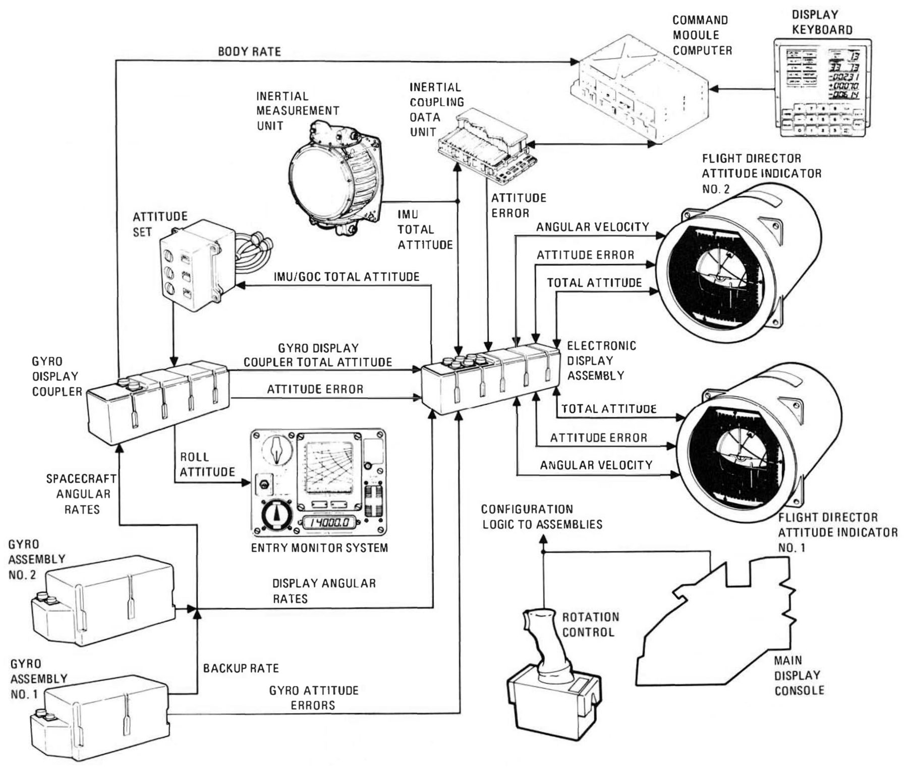
Gyro Assemblies (Honeywell) – Two gyroscope assemblies, each 6.00" x 7.00" by 14.25" and weighing 22.44 lb, were mounted on the navigation station lower equipment bay left side. Each gyro assembly contained three attitude gyros mounted so that each had an input axis parallel to a spacecraft body axis. Each assembly comprised a welded aluminum alloy enclosure that provided vacuum sealing and electrical continuity, and contained the gyroscopes, associated power, sense and control electronics.
Gyro assembly No. 1 provided signals to display attitude change rates on the FDAIs, for rate damping, and for inertial attitude change computation. Gyro assembly No. 2 provided signals for body rate displays the FDAIs, rate damping for stabilization and control subsystem control configurations (excluding acceleration command and minimum impulse), and inertial attitude change computations. The gyros provided signals equivalent to body attitude errors. These signals were used for attitude control and/or attitude indicator display. These gyros could also provided backup rate signals for gyro assembly No. 2 functions. Two control schemes were selectable from the main display console – CMC (primary) or SCS (backup). Attitude control was obtained from the RCS engines and SPE thrust vector control.
The gyro display coupler provided attitude reference signals to the FDAIs for spacecraft total attitude and attitude error display. Displayed angular velocity was always supplied from either of the two gyro assemblies. The spacecraft total attitude display required a connection between either gyro assembly and the attitude ball. This combination provided a backup attitude reference system for accurate display of spacecraft position relative to a given set of reference axes. Spacecraft attitude errors were developed using the attitude set control panel connection between the gyro display coupler and the attitude indicator error needles. This combination provided a means of aligning the attitude reference system to a fixed reference while monitoring the alignment process on the error needles; it can also be used in conjunction with manual maneuvering of the spacecraft.
Spacecraft and system functions were monitored via the total attitude, attitude error, and rate indications. Since a single source could supply more than one information type, the mission function required at a particular time would normally dictate what type of information was required from the source. The FDAI was modified by an electrically-inserted earth/moon orbital rate display to provided a local pitch axis vertical display with respect to the body (earth or moon) the spacecraft was orbiting. Controls on the unit permitted selection of earth or lunar orbits and orbital attitude adjustment.
2.2 SCS Controls and Displays
The SCS/crew interface comprised two rotation controls, a translation control, an attitude set control panel, a gimbal position and fuel pressure indicator, two FDAIs, and two gyro assemblies.
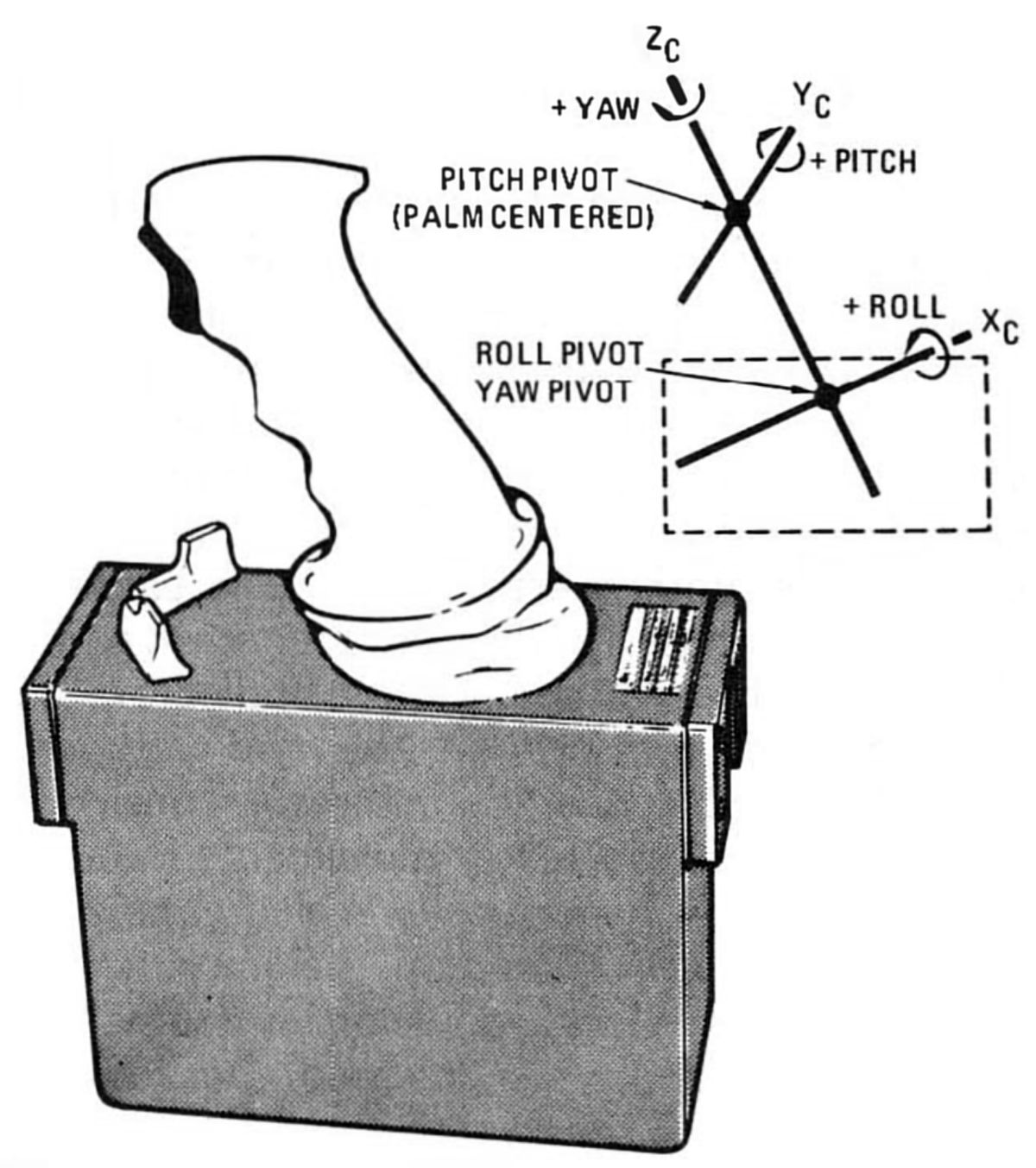 |
| Rotation Control |
Rotation Controls (Honeywell) – Two identical three-axes rotation controls provided proportional rate command signals for attitude or manual thrust vector maneuvers. Control motion was analogous to spacecraft rotation about its axes. Direct angular acceleration command signals were provided when the direct RCS switches were actuated and the control stick was displaced to full-stop position. The rotation controls could be mounted on left and right couches and at the lower equipment bay navigation position. Each control, including cable and connector, weighed 7 lb and comprised a 3.00" x 5.50" x 7.26" metal box with a 5.25" aluminum stick, which included a trigger-type push-to-talk switch. Redundant locking devices on each control prevented inadvertent actuation. The rotation control unit included six breakout switches to provided on-off command signals to the CMC, along with proportional rate commands that drove the SPE gimbal position in pitch and yaw during manual thrust vector control and RCS thrusters during coasting flight and SPS thrusting.
The rotation controls, connected in parallel, operated in a redundant fashion without switching and allowed the crew to rotate the spacecraft about all three axes. Each rotation control axis comprised three functions:
1. A breakout switch closure occurred when the control was moved 1.5° from its rest position. Each axis had separate switches for each rotation direction. These six switches provided command signals to the CMC, stabilization and control minimum impulses, acceleration commands, attitude gyro caging, and proportional rate commands.
2. Transducers produced alternating current signals proportional to the rotation control displacement; these signals commanded spacecraft rotation rates. Redundant switches closed for each control displacement direction; these switches commanded the CMC and the reaction jet and engine control.
3. Separate direct switches for each attitude axis and each rotation direction closed when the control was moved a nominal 11° from its null position (hardstops limited control movement to ±11.5° from null in all axes). These switches were enabled by placing the DIRECT RCS switch to ON. Direct switch closures produced acceleration commands through the RCS engine direct solenoids, bypassing all SCS electronics.
The rotation control has a tapered female dovetail on each end of the housing which mated with mounting brackets on the couch armrests and at the navigation station in the lower equipment bay. When attached to the armrests, the input axes were approximately parallel with spacecraft body axes. The control was spring-loaded to null in all axes. A trigger-type push-to-talk switch also were located in the control grip. Redundant locking devices were provided on each control.
| Translation Control |
Translation Control (Honeywell) – A T-handle stick control provided a means of accelerating along one or more spacecraft axes. Translation control motion produced spacecraft translation motion. The thrust control metal box weighed 5 lb 11 oz, and measured 3.8" x 6.3" by 3.8". A 3" rubber boot sealed the box/T-handle junction. This control was mounted with its axes approximately parallel to those of the spacecraft. Redundant switches closed for each control displacement direction. The translation control T-handle could be rotated in either direction about its shaft centerline. Hardstops for these rotations were ±17° from null with detent positions encountered at a nominal ±12°. In the detent position the T-handle could be released and would not return to null. Clockwise switches transfer spacecraft control from the PNGCS to the SCS; counterclockwise switches initiated abort sequences during launch.
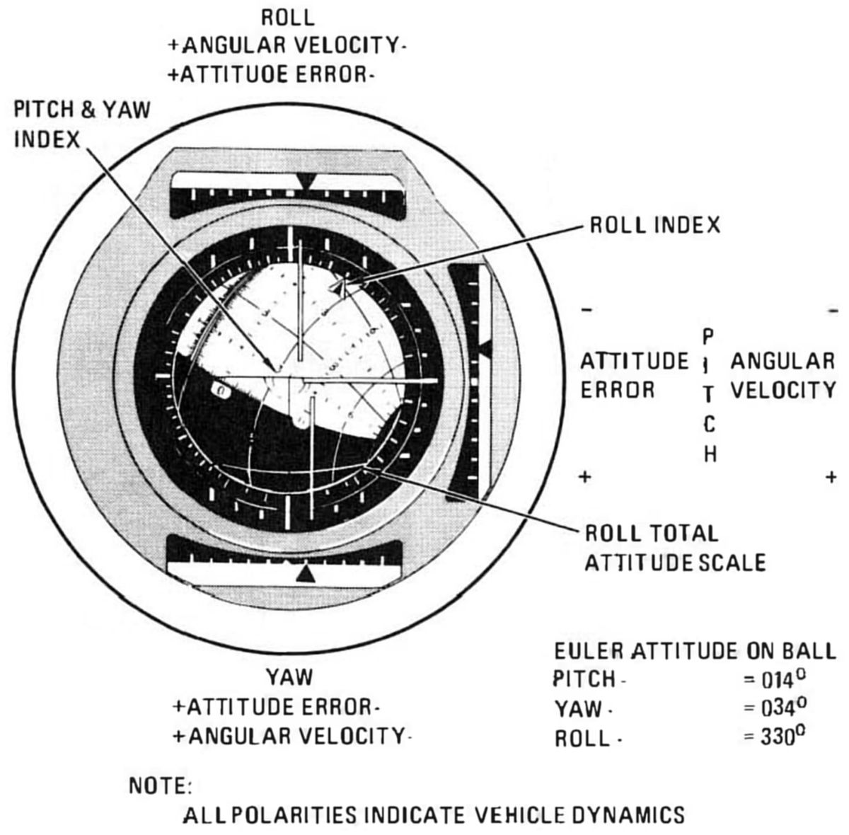
Flight Director Attitude Indicator (FDAI) (Honeywell) – Two indicators were each in a 9-lb metal box 6.9" in diameter and 9.3" long. One was located on Panel 1 in front of the commander and the other on a panel to the right, above the DSKY. The FDAI included a ball with circles showing pitch attitude, yaw attitude, and roll attitude, and three scales, one above, one below and the third to the right of the ball, showed pitch, yaw, and roll rates with needles showing pitch, yaw, and roll error. the The SCS or PGNCS supplied attitude and attitude error signals to the FDAIs. Rate signals to the displays were supplied by the SCS only.
 |
 |
| FDAI | |
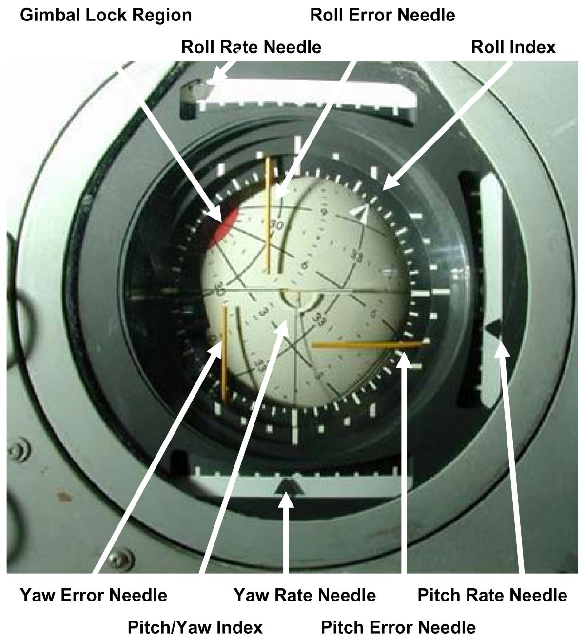
The FDAIs displayed body rate (roll, yaw, or pitch), which were derived from the body-mounted attitude gyros. Positive angular rates were indicated by a downward displacement of the pitch rate needle and by leftward displacement of the yaw and roll rate needles. The angular rate displacements were related to the direction of motion required by the rotation control to reduce the indicated rates to zero. The angular rate scales were marked with graduations at null and full range, and at 1/5, 2/5, 3/5, and 4/5 of full range. Full-scale deflection ranges were obtained with the FDA/ SCALE switch and were 1°, 5°, and 10° per second in pitch and yaw, and 1°, 5°, and 50° per second in roll. Servometric meter movements were used for the three rate indicator needles. The indicator's attitude error needles showed the difference between the actual and desired spacecraft attitude. Positive attitude error were indicated by a downward displacement of the pitch error needle, and by a leftward displacement of the yaw and roll error needles. The attitude error needle displacements also were related to the motion direction required by the rotation control to reduce the error to zero. The needle error ranges were 5° or 50° for full-scale roll error, and 5° or 15° for pitch and yaw error. The error scale factors were selected by a switch that also established the rate scales. The pitch and yaw attitude error scales contain graduation marks at null and full scale, and at 1 /3 and 2/3 of full scale. The roll attitude scale contains marks at null, 1/2, and full scale. The attitude error indicators also use servometric meter movements.
Spacecraft orientation with respect to a selected inertial reference frame was also displayed on the attitude indicator ball. This display contained three servo control loops that were used to rotate the ball about three independent axes. These axes correspond to inertial pitch, yaw, and roll. The control loops could accept inputs from either the inertial measurement unit gimbal resolvers or gyro display coupler resolvers.
Pitch attitude was represented on the ball by great semicircles. The semicircle displayed under the inverted wing symbol were the inertial pitch at the time of readout. The two semicircles that make up a great circle correspond to pitch attitudes of θ and θ + 180°.
Yaw attitude were represented by minor circles. The display readout were similar to the pitch readout. Yaw attitude circles were restricted to the intervals of 270° to 360°and 360° to 90°.
Roll attitude was the angle between the wing symbol and the pitch attitude circle. The roll attitude was more accurately displayed on a scale attached to the indicator mounting under a pointer attached to the roll (ball) axis. The last digits of the circle markings were omitted. Thus, for example, 3 corresponds to 30, and 33 corresponds to 330. The ball was symmetrically marked about the 0° yaw and 0/180° pitch circles. Marks at 1° increments were provided along the entire yaw 0° circle. The pitch 180° semicircles had the same marking increments as the 0° semicircle. Numerals along the 300° and 60° yaw circles were spaced 60 pitch degrees apart. Numerals along the 30° yaw circle were spaced 30 pitch degrees apart.
Red ball areas indicated IMU gimbal lock, a phenomenon that occurred when two or more IMU axes became aligned, causing loss of IMU attitude sensing capability. The 1963 decision to use just three stable platform isolation gimbals and accept the operational nuisance of gimbal lock was based upon the weight, power, reliability, and performance advantages of avoiding the fourth gimbal. As a result, Apollo attitude maneuvers had to avoid moving the spacecraft thrust axis closer than about 10° to the inertially-aligned inner member axis. By proper choice of IMU alignment, every phase of the Apollo mission could avoid gimbal lock attitudes. The forbidden zones were small and conceptually simple. If IMU attitude was lost due to gimbal lock or any other cause, the IMU was undamaged, a warning signal was given, and the procedures for realignment were straightforward.
Flight experience uncovered an unanticipated gimbal lock aspect. In some flight regimes the crews of earth orbital flights Apollo 7 and Apollo 9 noticed a tendency for aerodynamic torquing or gravity-gradient torquing to rotate the spacecraft towards gimbal lock when the IMU had particular alignments. On each earth orbit flight the spacecraft rotated into gimbal lock while not being watched. Neither crew expressed particular alarm over the event, but they complained about the constraint.
The gimbal lock problem disappears while the IMU is not operating and early mission planners expected this to be the case because of spacecraft electrical power constraints. However, the IMU was left running and aligned during the entire Apollo 8 mission and this became the rule rather than the exception for all lunar missions. At least one crewman was awake at any time and could watch for possible random spacecraft tumble into gimbal lock. The near earth torquing effect absent, IMU alignment loss due to gimbal lock did not occur.
However, the attitude constraint imposed by gimbal lock was an awkward nuisance, requiring consideration by mission designers and crew during attitude maneuvers. It also reared its ugly head during the Apollo 13 emergency, adding additional stress for the already overworked crew.
During the Apollo 9 flight and experimental program was loaded into erasable memory and caused the computer to take over automatic attitude control in a wide deadband. This resulted in extremely efficient reaction control fuel usage. The crew felt that they would be willing to operate in this mode while all three slept; the control system would keep attitudes well away from gimbal lock. In hindsight, designers would have chosen an all-attitude IMU with the necessary redundant gimbal or implemented a computer algorithm to remove the gimbal lock nuisance.
 |
| Attitude Set Control Panel |
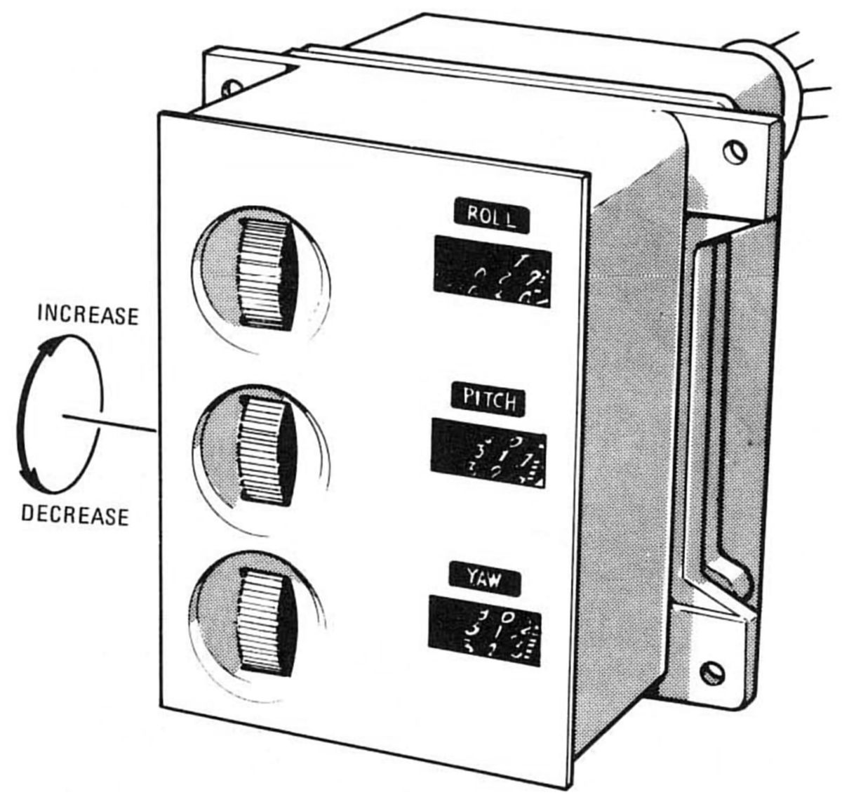
Attitude Set Control Panel (Honeywell) - This 3.5" x 4.8" by 4.4" panel weighed 3 lb 6 oz and was mounted in the lower left-hand corner of the main display panel facing the commander. Its three windows displayed roll, pitch, and yaw in degrees and three thumbwheels to the left of the windows were used to manually set desired SCS attitude information in the form of roll, pitch and yaw angles. It received signals that represented the actual spacecraft attitude relative to an arbitrary inertial (fixed) reference frame. Output signals represented the attitude error or the difference between the actual and desired total spacecraft attitude. These signals drove the FDAI attitude error needles, thereby providing the astronauts with a visual spacecraft attitude error indication and allowing gyro display coupler alignment to a fixed reference frame.
The attitude set control panel provided a thumbwheel to position resolvers for each of the three axes. The resolvers were mechanically linked with indicators providing a readout of the dialed angles. The signals to these attitude set resolvers were from the inertial measurement unit or the gyro display coupler. The panel counters indicated resolver angles in degrees, and allowed continuous rotation from 000° through 359° to 000° without reversing direction. There were graduation marks every 0.2°. Pitch and roll were marked continuously between 0° and 359.8°. Yaw were marked continuously from 0° to 90° and from 270° to 359.8°; it were also marked with 0.2° graduation marks from 270° to 0° to 90° and were numbered at 180°. Readings increased for an upward thumbwheel rotation. One thumbwheel revolution produced a 20° change in the resolver angle and a corresponding 20° change in the counter reading.
 |
| Gimble Position, Fuel Pressure |
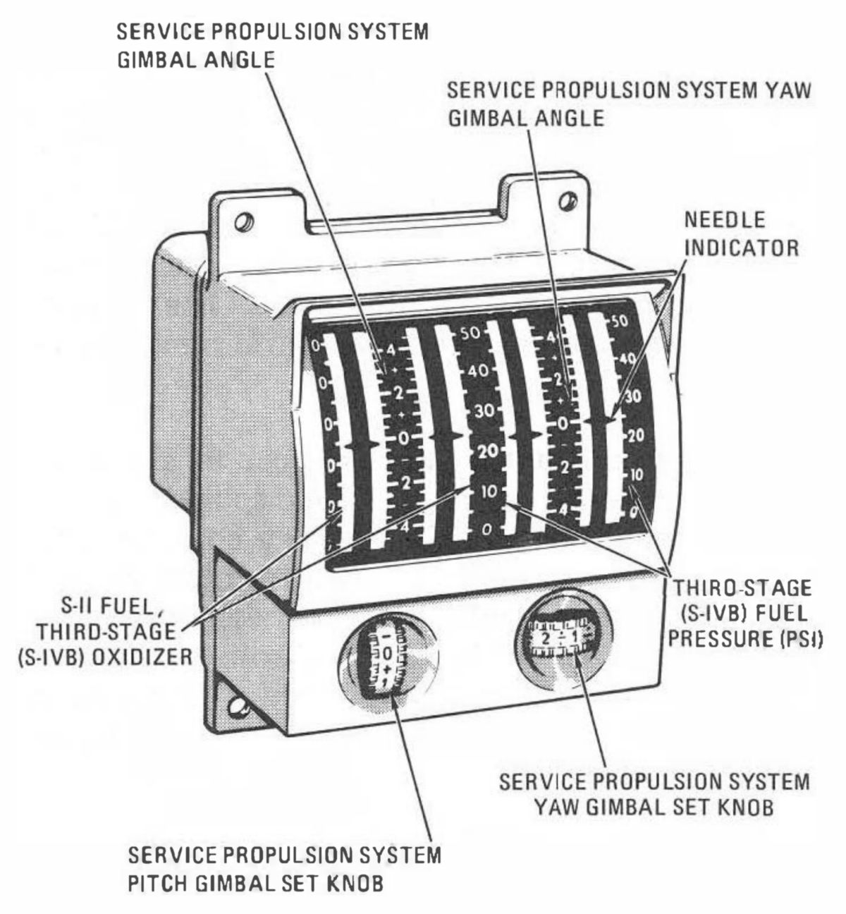
The gimbal position and fuel pressure indicator (Honeywell) was a 4.25" x 4.50" x 4.82" metal box with a single window showing four meter movements. The unit weighed 2 lb 14 oz and was directly below the commander's FDAI. It contained redundant indicators for both the pitch and yaw channels. During the boost phases the indicators display fuel and oxidizer pressures for the Saturn second and third stages. Second stage fuel pressure (or third stage oxidizer pressure depending on the launch vehicle configuration) were on the redundant pitch indicators while third stage fuel pressure were on the two yaw indicators.
The gimbal position indicator consisted of two dual servometric meter movements mounted within a common hermetically sealed case. Thumbwheels enabled the crew to set SPE gimbal angles for SCS velocity change maneuvers. Desired gimbal trim angles were set in with the pitch and yaw trim thumbwheels. The indicator displayed SPE position relative to actuator null and not body axes. The range of the engine pitch and yaw gimbal displays were ±4,5°. This range was graduated with marks at each 0.5° and reference numerals at each 2° division. The range of the fuel pressure scale were 0 to 50 psi with graduations at each 5-psi division and reference numerals at each 10-psi division.
2.3 SCS Operation
 |
| Attitude Control Equipment |
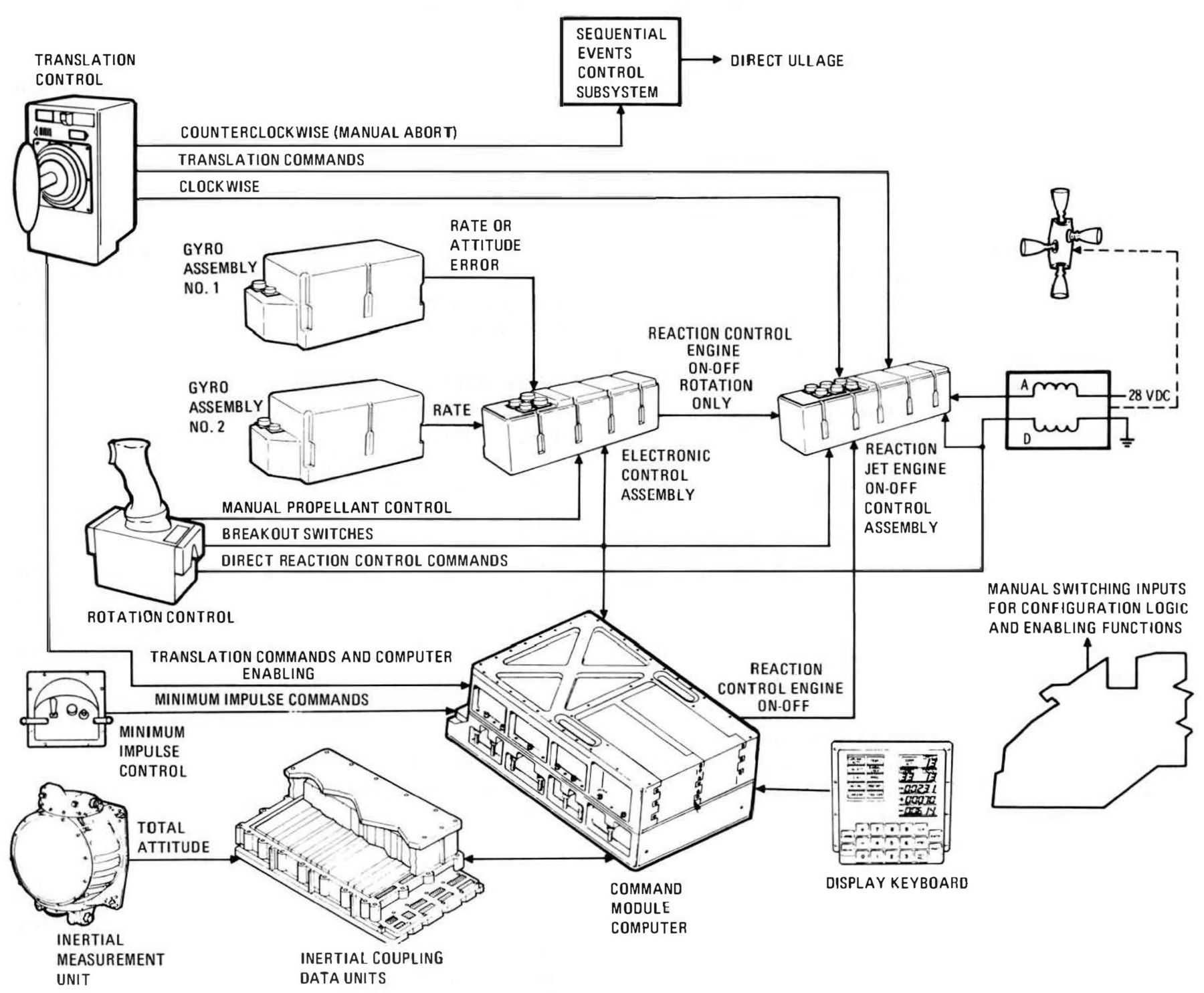
The RCS provided the rotation control torques and translational thrusts for all attitude and translation control functions. The RCS engines were operated by exciting a solenoid coil pair (fuel and oxidizer). Each engine had two solenoid coil pairs, one automatic and the other direct. Commands to the RCS engines were initiated by switching a ground through the solenoid driver to the automatic coil low sides. The solenoid drivers received commands from the automatic RCS logic circuitry contained in the reaction jet engine control. The automatic RCS logic activated the command source selected and commanded the necessary solenoid drivers to perform the desired attitude control function. The logic received reaction control commands from the CMC (for rotation and translation), the electronics control assembly (rotation for either automatic, proportional rate, or minimum impulse control), the rotation controls (for continuous rotational acceleration), and the translation control (for translational acceleration).
Commands to the direct coils had priority over commands to automatic coils. The direct coils received commands from the rotation control when the DIRECT RCS switch was actuated and the control was deflected 11° about one or more axes. The direct coils were used to command an ullage maneuver before a SPE firing if normal ullage methods were not available; this was controlled through a pushbutton on the main display console. The master events sequence controller also could command an ullage maneuver to enable CSM separation from the third stage. Direct coils on the SM reaction control engines were activated by the SM jettison controller for SM-CM separation. CM direct coils were activated by a switch on the main display console for reaction control propellant dumping during the final descent on the main parachutes.
Ullage maneuvers were required to settle the propellants in their tanks prior to starting the SPE. The propellants, because of surface tension, would tend to cling to the tank walls, leaving a void in the tank center that could introduce the helium pressurant into the rocket engine. Hence, a brief ullage burn preceeded each SPE burn.
The crew could set control panel switches that placed the SCS in various attitude control configurations. The desired configurations for both automatic and manual control could be independently selected for each axis. Automatic control included rate damping and attitude hold. In rate damping, large spacecraft rates were reduced to a small range (rate deadband) and held within that range. In attitude hold, angular deviations about the body axes were kept within certain limits (attitude deadband). If attitude hold were selected in pitch, yaw, and roll, the control could be defined as maintaining a fixed inertial reference. Rate damping was used in the mechanization of the attitude hold configuration. Attitude hold used summing electronics and a switching amplifier to process the body-mounted attitude gyro control signals and drive two RCS command terminals. One terminal provided positive rotation commands and the other negative commands. If the signal input magnitude was smaller than a specific value, neither output was obtained. The input level required to obtain an output was referred to as the switching amplifier deadband. This was interpreted as a rate deadband or an attitude (minimum) deadband. The deadband limits were a function of the control loop gains, which depend on the RATE switch position: low was ±0.2° per second and high was ± 2° per second. An additional deadband selectable for attitude control was ± 0.2° to 4.2° in low and ±4° to 8° in high. When the rate and attitude signal summation exceeded the switching amplifier deadband, a rotation command was sent to the RCS and the engines were automatically fired for the duration needed to correct the deviation.
Manual attitude control comprised proportional rate, minimum-impulse, acceleration command, and direct control. These commands were initiated by operation of either rotation control. With the exception of direct, the rotation control commands went through the RCS automatic coils. Proportional rate provided the ability to command a spacecraft rate that was directly related to the control stick deflection rotation amount . This capability was obtained by summing the control's transducer output with the body-mounted attitude gyro signal in the electronics control assembly; when the stick was deflected, an error were developed at the switching amplifier input that results in an acceleration command. The command was present until the gyro signal were large enough to reduce the error to less than the deadband. The spacecraft would then coast at a constant rate until the rotation control input was removed. Minimum impulse provided the ability to make small spacecraft rate changes When minimum impulse was enabled for an axis, the switching amplifier output for that axis was inhibited. Thus, the spacecraft attitude was in free drift in that axis if direct control was not being used. Minimum impulse was commanded by the rotation control breakout switch. When minimum impulse was selected in the roll axis, one-half of the roll solenoid drivers were inhibited for minimum impulse commands. A roll minimum impulse command was executed by two reaction control engines unless one of the "Channel Roll" switches was turned off, which reduced the command to a single engine. When acceleration commands were activated and a breakout switch was closed, continuous commands were sent to the appropriate RCS automatic coils. The selection of acceleration command in an axis inhibited all other inputs to the automatic RCS logic for that axis. This differed from minimum impulse selection in that translation control commands were available during minimum impulse control. Direct rotation control was available as backup to any other control, including CMC, when the DIRECT RCS switch was on. When the rotation control stick was deflected to hard stop, a direct switch was closed and voltage was routed to the direct coils on the appropriate reaction control engines. The control's direct switch also routed a signal to the automatic RCS logic that inhibited all automatic coil commands in the axis under direct control.
Commands from the translation control could be initiated simultaneously in the three axes and appeared as logic inputs to the automatic RCS logic. The logic signals were obtained from switch closures in the control. Translation control was not available after CM/SM separation.
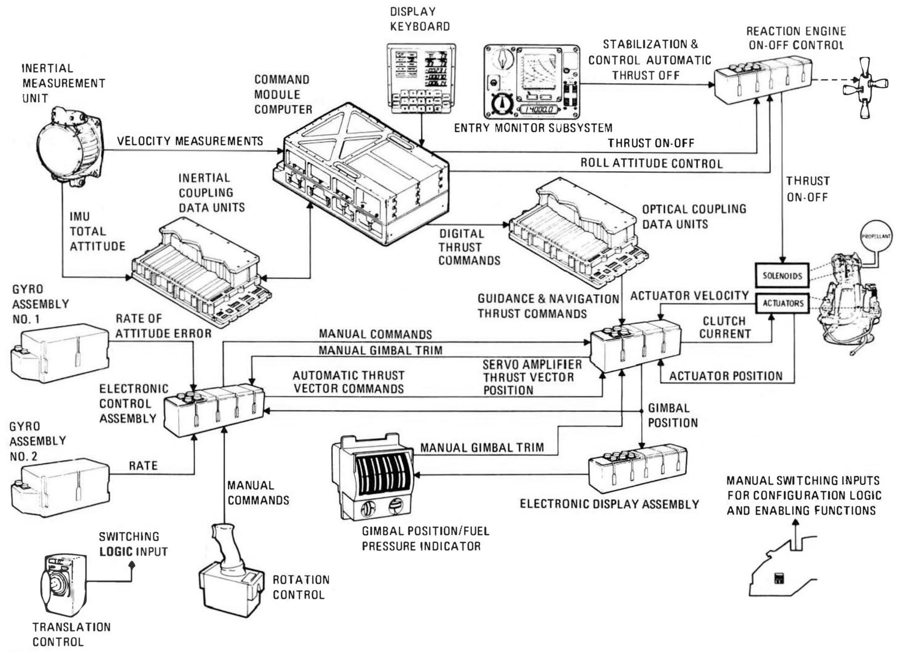
2.4 Thrust Vector Control
 |
 |
| SPE Gimballing, Thrust Vector Control Equipment | |
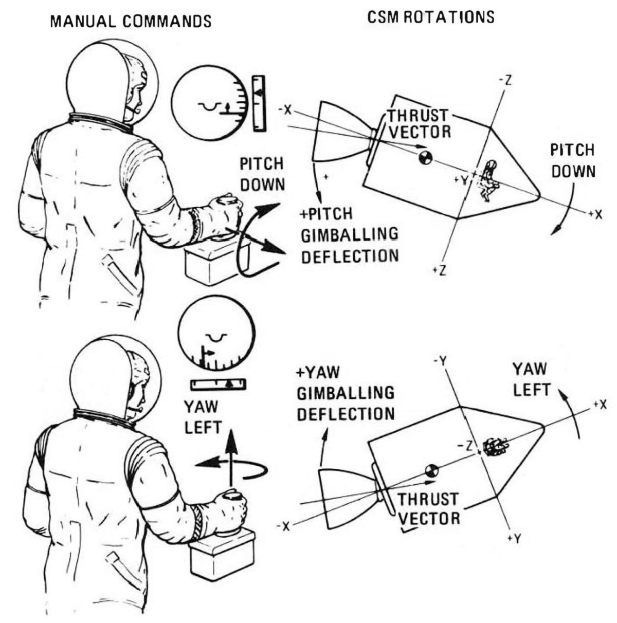
Spacecraft attitude was controlled during a velocity change by positioning the engine gimbals for pitch and yaw control while maintaining roll attitude with the attitude control subsystem. The stabilization and control electronics was configurable to accept attitude sensor signals for automatic control or rotation control signals for manual control. Manual thrust vector control could be selected to use vehicle rate feedback signals summed with the manual signals. A different configuration could be selected for each axis; for example, one axis can be controlled manually while the other were controlled automatically.
In automatic thrust vector control, spacecraft angular rates and attitude errors were sensed by the body-mounted attitude gyros. Attitude error, gimbal position, and gimbal trim signals were summed at the input to an integrator amplifier. The integrator output was then summed with rate, attitude error, gimbal position, and gimbal rate at the servo amplifier input. Steady-state operation was obtained when the gimbal was positioned so that the thrust vector was aligned through the vehicle center of gravity and the error at both summing points were a constant-zero. The integrator input error was zero when gimbal position minus gimbal trim was equal to the negative of the attitude excursion sensed by gyro assembly No. l. This was the spacecraft/gimbal orientation necessary to obtain and maintain the desired thrust direction. Transients due to center-of-gravity uncertainty errors or shifts during thrusting were forced by the integrator to have the necessary steady-state solution. However, final pointing vector errors will be incurred because of the quadrature accelerations induced during the transient phases. Errors also resulted from amplifier gain and component inaccuracies.
The gimbals were trimmed before thrusting by turning the trim wheels on the gimbal position indicator. The trim wheel in each axis was mechanically connected to two gimbal servomechanism potentiometers. It was desirable to trim before velocity change to minimize the transient duration time and the accompanying quadrature acceleration. The trim wheels also were set before a velocity change controlled by the CMC so that the SCS could adjust the desired thrust direction if a transfer were required after engine ignition. In manual thrust vector control, the rotation control signal was sent to a proportional plus integral amplifier. This circuit maintained a gimbal deflection after the rotation control was returned to rest and made corrections with the control about its rest position, thereby relieving the crewmember from holding a large rotation control displacement. Depending on how switches were set, it also could damp out spacecraft rate.
Rate command and acceleration command were the two manual thrust vector control configurations. Rate command was similar to the proportional rate control in the attitude control subsystem except there was no deadband. The thrust vector was under body-mounted attitude gyro control. If there was an initial gimbal center-of-gravity misalignment, an angular acceleration developed. The gyros, through the proportional gain, would drive the gimbals as necessary to cancel this acceleration. The rate feedback was inhibited in acceleration command, which meant the rotation control input had to be properly trimmed to position the thrust vector through the center of gravity. This drove the rotational acceleration to zero but additional adjustment was necessary to cancel residual rates and obtain the desired attitude and positioning vector.
3.0 Entry Monitor System
 |
 |
| EMS Block Diagram | EMS Display and Controls |
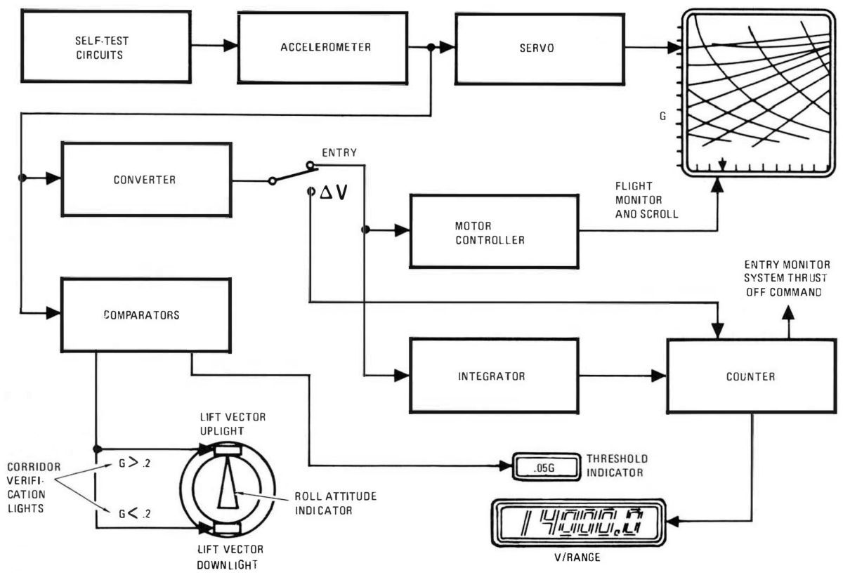
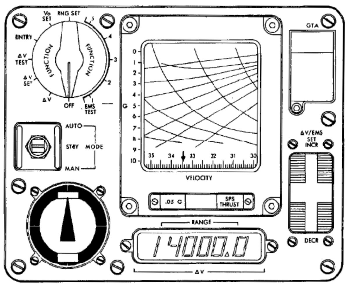
The entry monitor system (EMS) provided a visual display of automatic guidance navigation and control system entry and velocity change maneuvers. It also provided sufficient display data to permit manual entry in case of guidance and control malfunctions and automatic velocity cutoff commands for the stabilization and control subsystem when controlling the SPE. The velocity display also could be used to cut off thrust manually if the automatic commands malfunctioned.
The EMS provided five displays used to monitor an automatic entry or perform a manual entry: threshold indicator, roll attitude indicator, corridor verification indicators, range displays, and the flight monitor.
The threshold indicator, labeled .05G, displayed sensed deceleration. The altitude at which this indicator was illuminated depended on entry angle (velocity vector with respect to local horizontal), the magnitude of the velocity vector geographic location and heading, and atmospheric conditions. Bias comparator circuits and timers was used to activate this indicator. The signal used to illuminate the indicator was also used in the system to start the corridor evaluation timer, scroll velocity drive, and range-to-go circuits.
The roll attitude indicator displayed the lift vector position throughout entry. During entry, stability axis roll attitude was supplied to the indicator by the gyro display coupler. There were no degree markings on the display, but the equivalent readout was zero when the indicator pointed toward the control panel top and increases up to 360 in a counterclockwise direction.
The corridor verification indicators were located on the roll attitude indicator. They consisted of two lights that indicated the necessity for lift vector up or down for a controlled entry. (The indicators was valid only for spacecraft entering at velocities and angles that would be used during lunar return). The corridor comparison test was performed approximately 10 seconds after the .05G indicator was illuminated. The lift vector up light (top) indicated greater than approximately 0.2G. The lift vector down light (bottom) indicated less than approximately 0.2G. An entry angle was the angle displacement of the CM velocity vector with respect to local horizontal at 0.05G. The magnitude of the entry angles that determined the capture and undershoot boundaries depend on the CM lift-to-drag ratio. Entry angle less than the capture boundary resulted in noncapture regardless of lift orientation. Noncapture would result in an elliptical orbit that would reenter when perigee was again approached. The critical nature of this would depend on CM consumables — power, control propellant, life support, etc. The CM and crew would undergo excessive G force (greater than 10Gs) with an entry angle greater than the undershoot boundary, regardless of lift orientation.
The range display was an electronic readout of inertial flight path distance in nautical miles to predicted splashdown after 0.05G. The predicted range will be obtained from the guidance and control subsystems or ground stations and inserted into the range display before entry. The range display also showed velocity in feet per second during SPE thrusting.
The flight monitor provided an entry trace of total G level versus inertial velocity. A Mylar scroll had printed guide lines that provided monitor (or control) information during aerodynamic entry. The entry trace was generated by driving a scribe in a vertical direction as a function of G level, while the Mylar scroll was driven from right to left proportional to the CM inertial velocity change. Monitor and control information for safe entry and range potential was observed by comparing the entry trace slope to the nearest guide line slope.
In addition to entry functions, the entry monitor system provided outputs related to ΔV maneuvers during either service propulsion or reaction control engine thrusting. Displays include a lamp that illuminated any time the SPE fired and a counter that showed the velocity remaining to be gained or lost. The latter display range was 14,000 to -1000 fps in 0.1 fps. The desired velocity change for all SPE thrusting maneuvers was set in the panel and the display will count up or down. During thrust controlled by the stabilization and control subsystem, the entry monitor system automatically turns off the SPE when the display reads minus values.
The entry monitor systems flight monitor Mylar scroll had ground and flight test patterns together with four entry patterns. Each entry pattern was preceded by two identical flight test patterns and entry instructions that were used to verify the system's entry circuit operation and set initial conditions. Each entry pattern contained velocity increments from 37,000 to 4,000 feet per second as well as entry guidelines. The entry guidelines was called G on-set or G off-set and range potential lines. During entry the scribe trace should not become parallel to either the nearest G on-set or G off-set lines. If the entry trace slope became more negative than the nearest G on-set line, the CM should be oriented to produce a positive lift vector orientation (lift vector up), which prevented excessive G buildup. If the entry trace slope became more positive than the nearest G off-set line, the CM should be oriented to produce a negative lift (lift vector down). The G on-set and off-set lines were designed to allow a 2-second crew response time and a 180° roll maneuver if the entry trace becomes parallel to the target of the nearest guideline.
The range potential lines, shown in hundreds of nautical miles, were used by the crew during entry. They indicated the ranging potential of the CM at its present G level. The crew compared the range displayed by the range-to-go counter with the range potential indicated at the position of the entry trace. The slope and position of the entry trace relative to a desired ranging line indicates the need for lift vector up or down.
The vertical scroll line corresponded to where the CM velocity became suborbital, i.e., the velocity had been reduced below that required to maintain orbit. The full positive lift profile line represented the steady-state minimum-G entry profile for an entry.
4.0 Guidance and Navigation
 |
 |
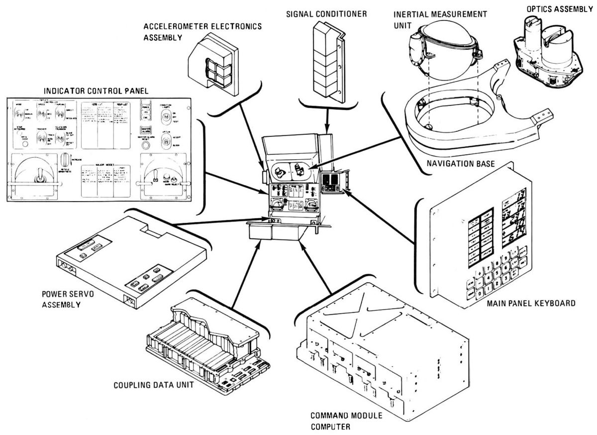 |
| GNS Block Diagram | GNS Equipment | |
The guidance and navigation subsystem (GNS) facilitated spacecraft navigation through space. The GNS provided primary thrust control. Astronauts oriented the spacecraft to the correct attitude and then used the DSKY to preset burn start time and duration. Accelerometers then sensed the resulting velocity change (ΔV). Thrust direction control was required because the spacecraft center of gravity shifted due to propellant depletion. Electromechanical actuators positioned the gimbaled SPE. Automatic control commands originated in either the GNS or the SCS. Astronauts could operate the GNS either semi-automatically or manually and perform the required guidance and navigation functions. It could be updated via ground telemetry. Sightings from the spacecraft of stars and pre-determined earth and lunar landmarks were used to establish the spacecrafts location and trajectory. The GNS was used in conjunction with the SCS, SPS, RCS, electrical power, environmental control, and telecommunications subsystems.
MIT was responsible for GNS design and development. AC Electronics Division of General Motors was responsible for its production, operation, and integration. The CMC was manufactured by the Raytheon Co. and the optics was produced by Kollsman Instrument Co.
The GNS components, including the primary controls and displays, occupied a command module lower equipment bay space 4 feet high x 2 feet deep x 3 feet across the top and 2.5 feet across the bottom. The main display console contained the switches and displays that allowed astronauts to control the spacecraft while in their couches.
4.1 Inertial Guidance Subsystem (IGS)
 |
 |
 |
 |
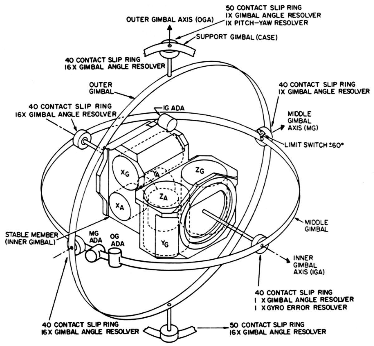
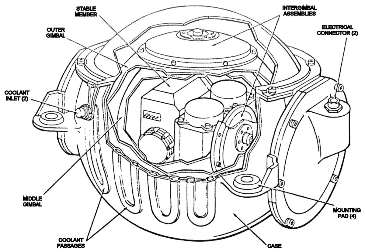
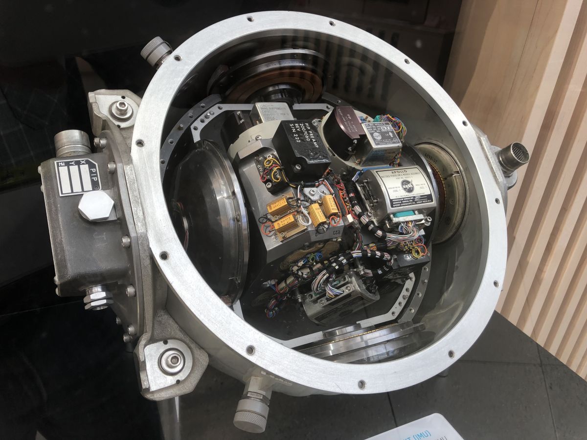
| IMU Schematic | IMU Cutaway | IMU Open (Arnold Reinhold) | Inertial System Schematic |
The IGS main component was an inertial measurement unit (IMU) mounted on a navigation base. The IMU, manfactured by AC Electronics Division of General Motors, had a 12.6" diameter and weighed 42.5 lb. It consisted of three gimbals of which the inner gimbal was a three degree-of-freedom stabilized platform assembly, containing three can-shaped inertial reference integrating gyros, and three can-shaped pulsed-integrating pendulous accelerometers. The stable member was machined from a solid block of beryllium with holes bored for mounting the gyros and accelerometers. The gimbals were connected to one other by drive motors and angle resolvers. The IMU was pressurized with dry air for good heat transfer. When in operation, the unit required 217 watts at 28 VDC. The IMU was aligned to star/earth/moon direction references and retained this alignment regardless of the spacecraft rotational movement, thus providing a reference against which spacecraft movements could be measured. Any change from the pre-determined flight path or attitude generated electronic signals that caused RCS engine firing(s) and/or SPE firings for flight path changes. Resolvers, mounted on the gimbal axes, measured how far the spacecraft rotated with respect to the stable platform. These measurements were transmitted to the CMC. While the gyros were used to maintain the spacecraft attitude, the resolvers were primarily to orient the spacecraft when firing the SPE. The IGS was controlled automatically by the CMC through crew selection of a computer program.
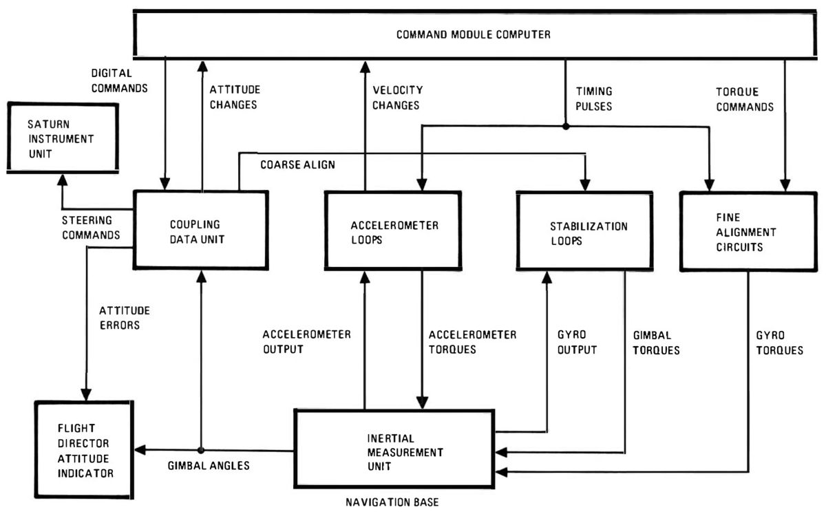
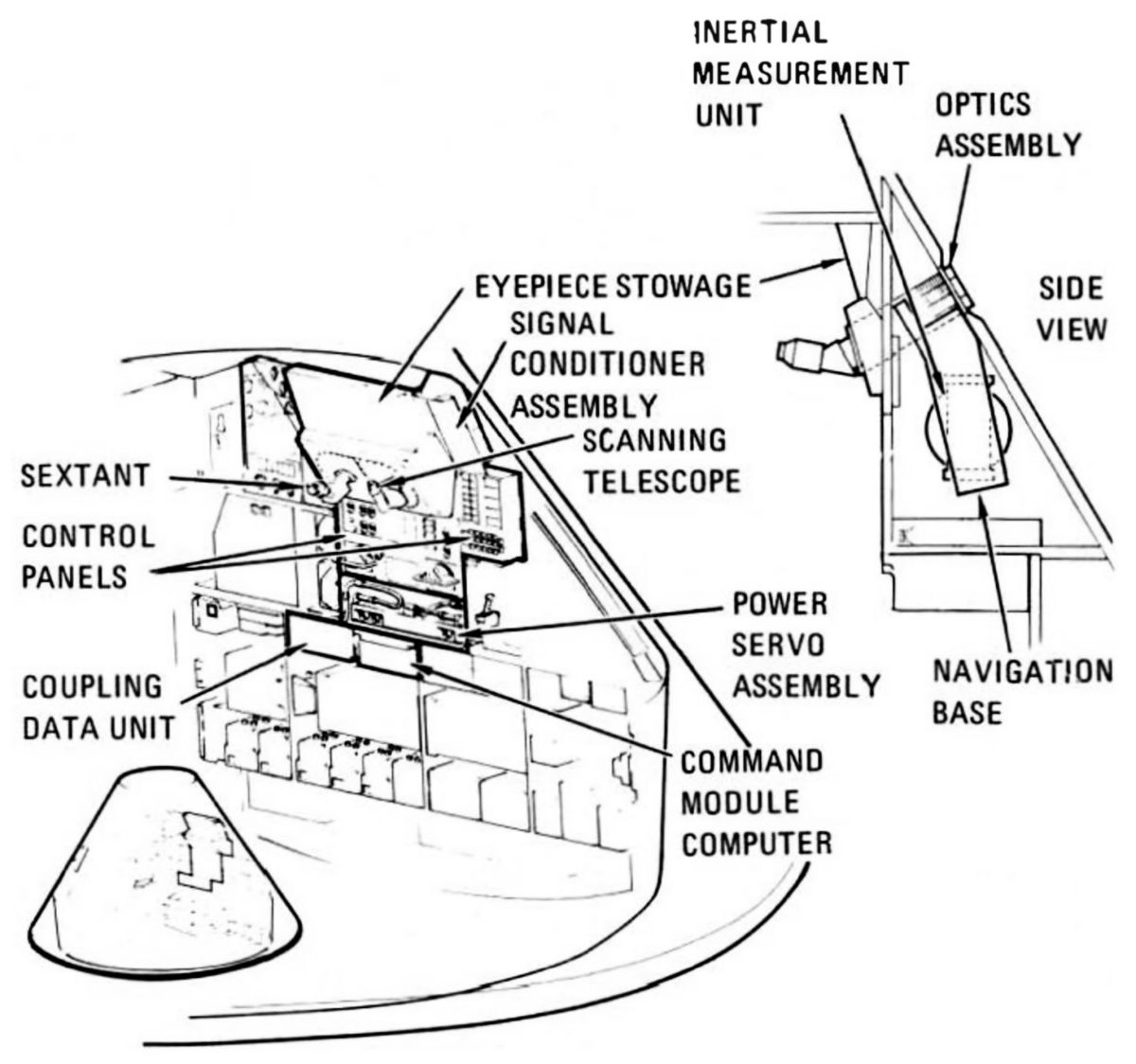
The inertial subsystem provided a space-stabilized inertial reference from which velocity and attitude changes were sensed. It was composed of the IMU, the navigation base, and depended on portions of the power and servo assembly, control and display panels, and the coupling data unit. The navigation base was a rigid supporting structure on which the IMU and optical instruments were mounted. It was manufactured and installed to close tolerances, providing accurate alignment and shock mounting for the IMU and optics.
The stable platform attitude was maintained by the gyros, stabilization loop electronics, and gimbal torque motors. Any stable platform angular displacement was sensed by the gyros, which generated error signals that were resolved and amplified at the IMU and applied to stabilization loop electronics. The resultant signal was conditioned and applied to the gimbal torque motors, restoring the desired attitude. The stable platform provided a space-referenced mount for the three orthogonally-mounted accelerometers, which sensed velocity changes along all three axes. Any translational force experienced by the spacecraft caused an acceleration or deceleration that was sensed by one or more accelerometers. Each generated an output signal proportional to the ΔV magnitude and direction. This signal, in the form of a pulse train, was sent to the CMC, which used it to update velocity information.
IMU temperature was controlled within required limits by a thermostatic system that applied heat via end-mounted heaters on the inertial components, stable member heaters, and a temperature control anticipatory heater. Heat was removed by convection, conduction, and radiation. The natural convection used during IMU standby modes was changed to blower-controlled, forced convection during operating modes. IMU internal pressure was normally 3.5 – 15 psia, enabling the required forced convection. To aid in removing heat, a water-glycol solution passes through coolant in the IMU outer case.
The Navigation Base (AC Electronics) was 27.0" x 22.0" x 4.5", weighed 17.4 lb, and was made of riveted and bonded preformed anodized aluminum alloy sheet. It was filled with polyurethane foam and formed a rigid supporting structure for the IMU and optical equipment.
The Power and Servo Assembly (AC Electronics) was 2.8" high, 23.1" wide, 22.6" deep and weighed 49.4 lb. It contains 37 electronic modules, most for the inertial and optical subsystem servo loops and power supplies.
The Coupling Data Unit (AC Electronics) - was 20.0" x 11.3" by 5.5" and weighed 36.5 lb. This sealed unit contained modular packaged solid-state electronics necessary to provided five separate coupling data unit channels for use with inner, middle, and outer IMU gimbal resolvers and the shaft and trunnion resolvers of the optical subsystem. It contained failure detection circuitry for the inertial and optical subsystems. It provided analog-to-digital conversion of the IMU gimbal angles and optical subsystem trunnion and shaft angles, and digital-to-analog conversion of computer-derived data to control inertial and optical subsystems operation modes using discretes issued by the CMC. It also controlled service propulsion system engine gimbaling, attitude error display, and, as a backup mode, the launch's vehicles third stage attitude.
The power and servo assembly was a central collection of GNS power supplies, amplifiers, and other electronic components. It was located in the lower equipment bay directly beneath the IMU and consisted of 42 modules mounted to a header assembly with integral connectors and harnesses. A thin cover plate established a hermetic seal for its interior. The assembly was pressurized to 15 psia during flight. Connectors were available for measuring signals at various system test points.
4.2 Optical Subsystem
 |
 |
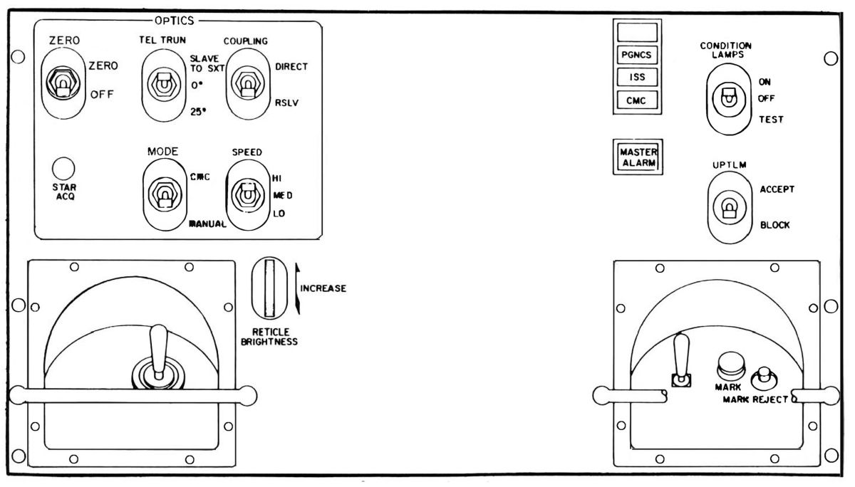 |
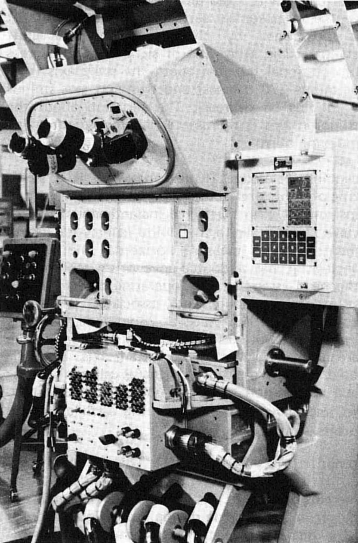
| Optical Installation | Optics | Optics Control Panel |
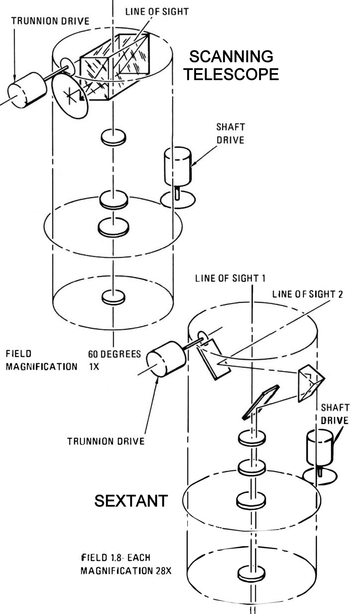
The optical subsystem, manufactured by the Kohsman Instrument Co. of Syosset, New York, was used by the astronauts to take navigational sightings of the stars and terrestrial or lunar landmarks. It consisted of a navigation base, a scanning telescope, a sextant, and equipment to permit operation with the CMC and IGS. The telescope and sextant could be operated independently but were generally used together to obtain precision navigational sightings. These two instruments were used to measure the angle between two targets such as stars and earth/moon landmarks. The telescope and then the sextant were manipulated by the astronaut to line up a sighting and enter the reading into the CMC.
The scanning telescope was a single line-of-sight, refracting 1x magnification instrument with 60° instantaneous field of view. It was similar to a theodolite (a surveyor's instrument used to measure horizontal and vertical angles). It had a double-dove prism mounted in the head assembly. The operating power for the telescope, sextant, and associated electronic equipment was 94.5 watts at 28 VDC. The telescope had two axes of rotational freedom, which was normally slaved to the sextant axis. The wide field of view was used for general celestial viewing and recognition of target bodies. It was also used to track landmark points during earth and lunar orbits.
The sextant was a highly accurate dual line-of-sight electro-optical, 28x magnification, 1.8° field of view instrument that could sight two celestial targets simultaneously and measure the angle between them with 10 arc seconds accuracy to determine spacecraft position. The sextant was mounted on the navigation base. One line of sight was fixed along the shaft axis normal to the spacecraft local conical surface. It was positioned by spacecraft attitude changes. The other line of sight had 2° of rotational freedom about the shaft axis (plus or minus 270°) and trunnion axis (minus 5° to plus 50°). The variation about the trunnion axis was represented by movement of an indexing mirror.
4.3 Command Module Computer (CMC)
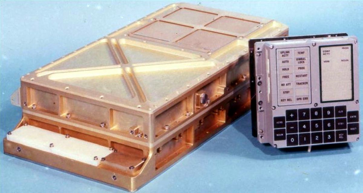 |
| Command Module Computer, Display/Keyboard (Grabert) |
The CMC, designed by the Massachusetts Institute of Technology (MIT) Instrumentation Laboratory and built by the Raytheon Co., was 24" x 12.5" x 6" (0.97 ft³) gold-alodined aluminum alloy box that weighed 70.1 lb. It power consumption was 55 watts at 28 VDC. It solved guidance and navigation problems, provided control information to spacecraft systems, provided pertinent information to astronauts and the ground controllers, provided means by which astronauts or ground control could directly communicate with the PNGCS, provided direct on-off control for reaction control jets and the SPE, and monitored its own and other PNGCS operations.
The information display that resulted from computations, and the control of the computer by the astronauts was accomplished with two display-keyboard (DSKY) panels. One was located in the lower equipment bay and the other (a duplicate) was on the main display console. Lights on the panels also indicated GNS malfunctions.
The display keyboard (DSKY) was an 8" x 8" x 7" panel that weighed 17.5 lb. It consisted of a keyboard, power supply, decoder relay matrix, status and caution circuits, and displays. It had a 21-digit character display and a 16-button keyboard through which crewmen could communicate in a coded numerical language. Crewman fed the CMC commands and data by punching numbers on the keyboard, which were then displayed by electroluminescent readouts. The CMC communicated with the crewman by displaying numbers in the same readouts. When the CMC requested the crewman to take some action, the numbers flash to attract attention.
The signal conditioner assembly was a 3.0" x 5.7" x 14.3" unit weighing 5.8 lbs. It contained encapsulated electronic circuitry to condition GNS signals so they were compatible with the spacecraft telemetry system.
The CMC is further covered in another article.
4.4 GNS Operation
Typical GNS operation during specific flight phases, control modes, and critical maneuvers is described below.
To conserve electrical power and fuel, the GNS was activated only about 20% of the time for specific sightings, alignments, and engine-firing maneuvers. Each time the GNS was activated the IMU stable platform required alignment. Before launch the platform was aligned with respect to the earth and during flight it was aligned to the stars.
Launch and Translunar Injection – The GNS monitored launch vehicle guidance through translunar injection, which set the spacecraft on a trajectory to the moon. At launch, the IMU was switched from an earth reference frame to a space reference frame. The crew then used the GNS to monitor the spacecraft flight profile.
Earth and Lunar Orbit – The crew checked the spacecraft position and orbital path with optical sightings during earth and lunar orbit. These sightings identified and tracked landmarks with the optical instruments. The CMC recorded optical sighting data, optical sighting time and spacecraft attitude.
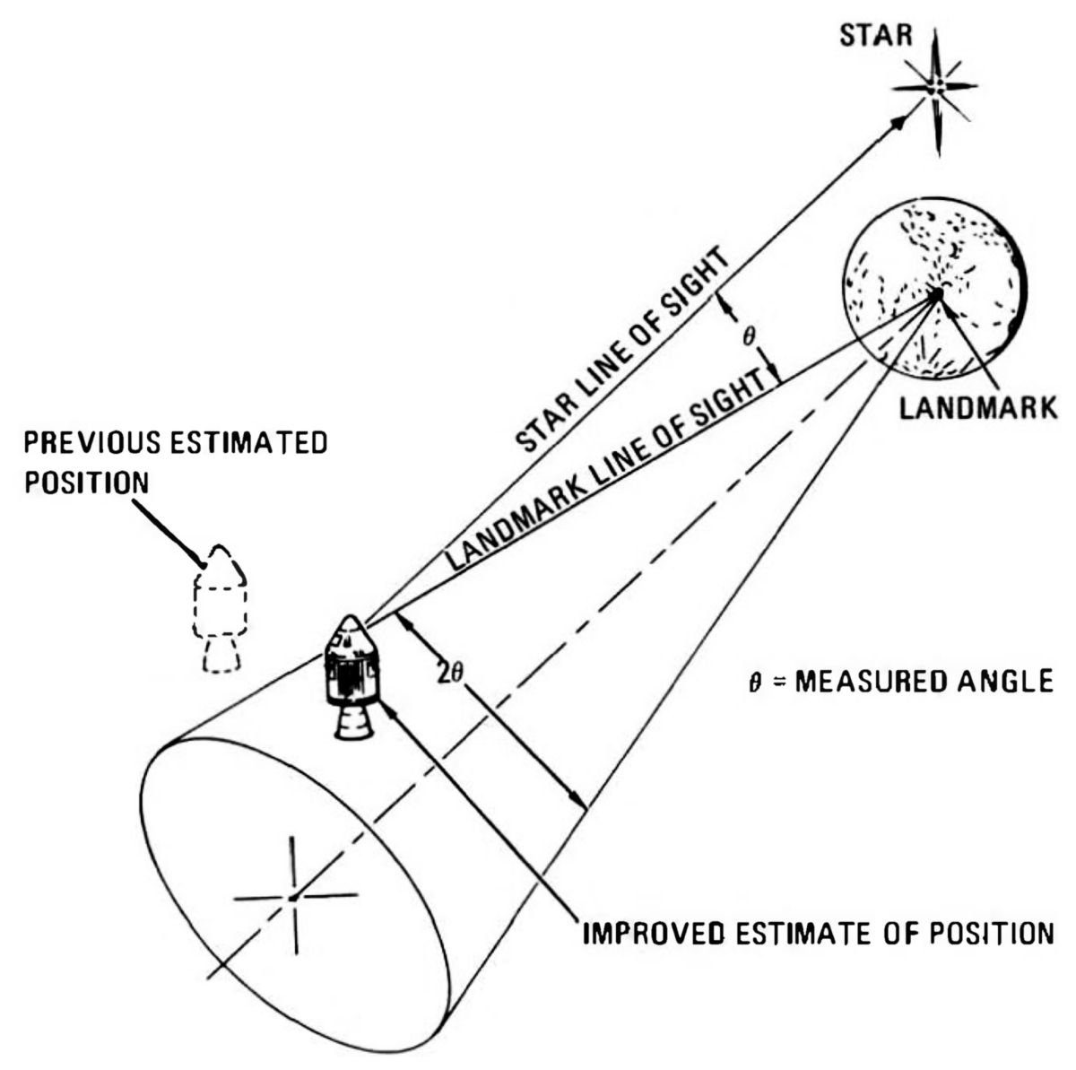 |
| Midcourse Navigation |
Midcourse Navigation – During the translunar and transearth mission phases, midcourse navigation might be performed several times. Star-landmark sightings were taken and the CMC recorded the sighting angles and times to determine spacecraft position and velocity.
Course Correction – If the spacecraft's course correction was required during either the translunar or transearth journeys, the CMC, after calculating spacecraft position and velocity from navigation sightings, compared the actual and required trajectories. If a course correction was necessary, the CMC calculated the firing time and velocity change needed, repositioned the spacecraft, and controlled SPS engine thrusting initiation and duration.
Lunar Injection and Earth Return – The GNS placed the spacecraft into the attitude required for firing the SPS engine and controlled the thrusting time.
Entry – The GNS controlled the command module flight path during earth atmospheric entry. The CMC determined the proper trajectory and steered the command module by rolling it. This changed the lifting force acting on the command module and thereby varied its trajectory.
References
Apollo Guidance and Navigation System (Block I, Series 100) Student Study Guide (El Segundo, California: General Motors Corp., AC Electronics Division, 1 Jun 1965).
Apollo Spacecraft News Reference (Downey, California: North American Rockwell Space Division, 1967?).
Interbartolo, Michael Apollo Guidance, Navigation and Control (GNC) Hardware Overview JSC-17237-1, NTRS 20090016290 (Houston, Texas: NASA Johnson Space Center, 1 Jan 2009).
Interbartolo, Michael Apollo Onboard Navigation Techniques, JSC-17237-3, NTRS 20090016292 (Houston, Texas: NASA Johnson Space Center, 1 Jan 2009).
Send mail to
![]() with questions or comments about this web site.
with questions or comments about this web site.
![]()