USSRC LMAE
U.S. Manned Rocket Propulsion Evolution
Part 9.44: The Lunar Module Ascent Engine (LMAE)
Compiled by Kimble D. McCutcheon
Published 28 Dec 2021; Revised 4 Aug 2022
USSRC LMAE |
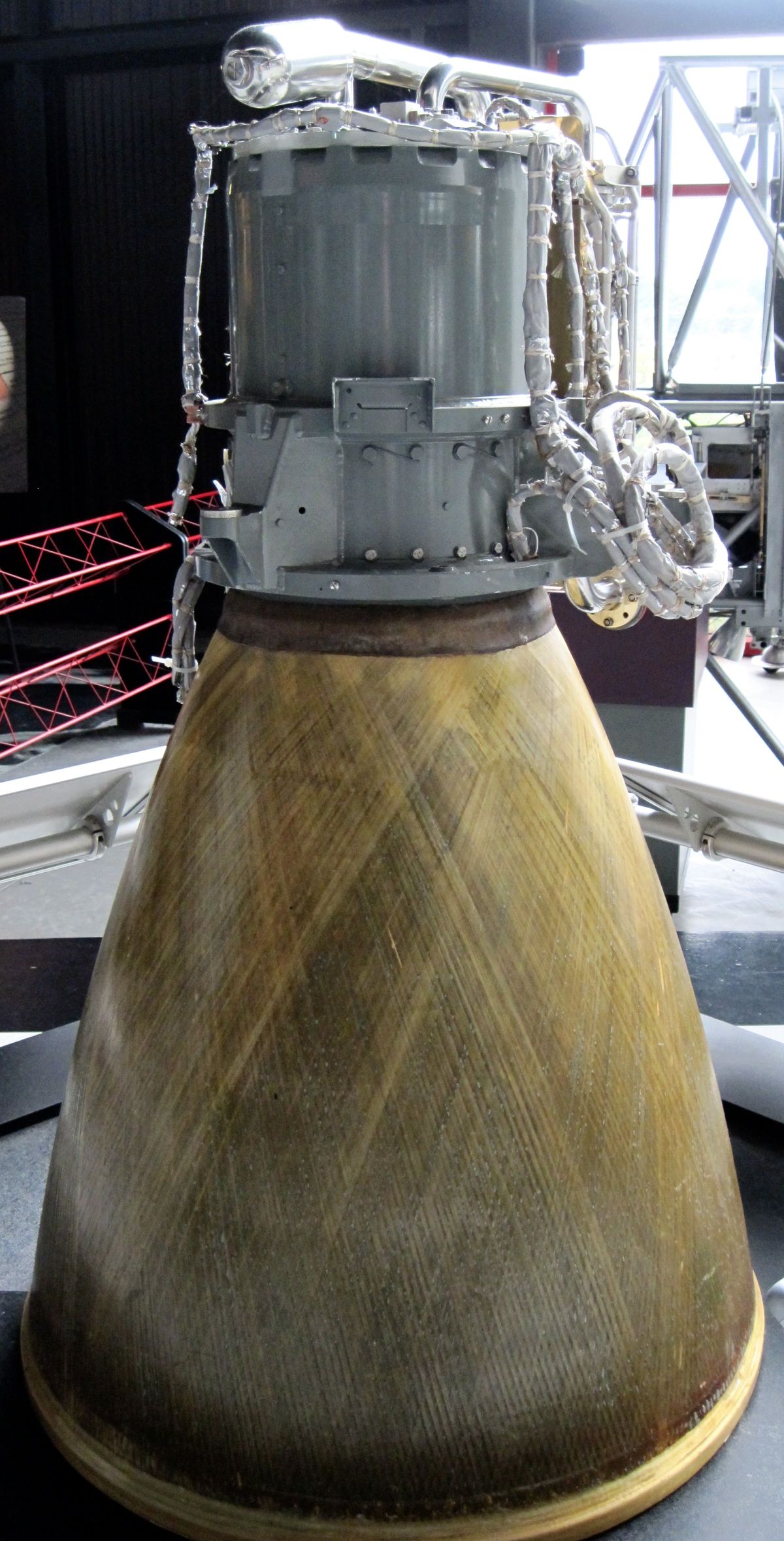
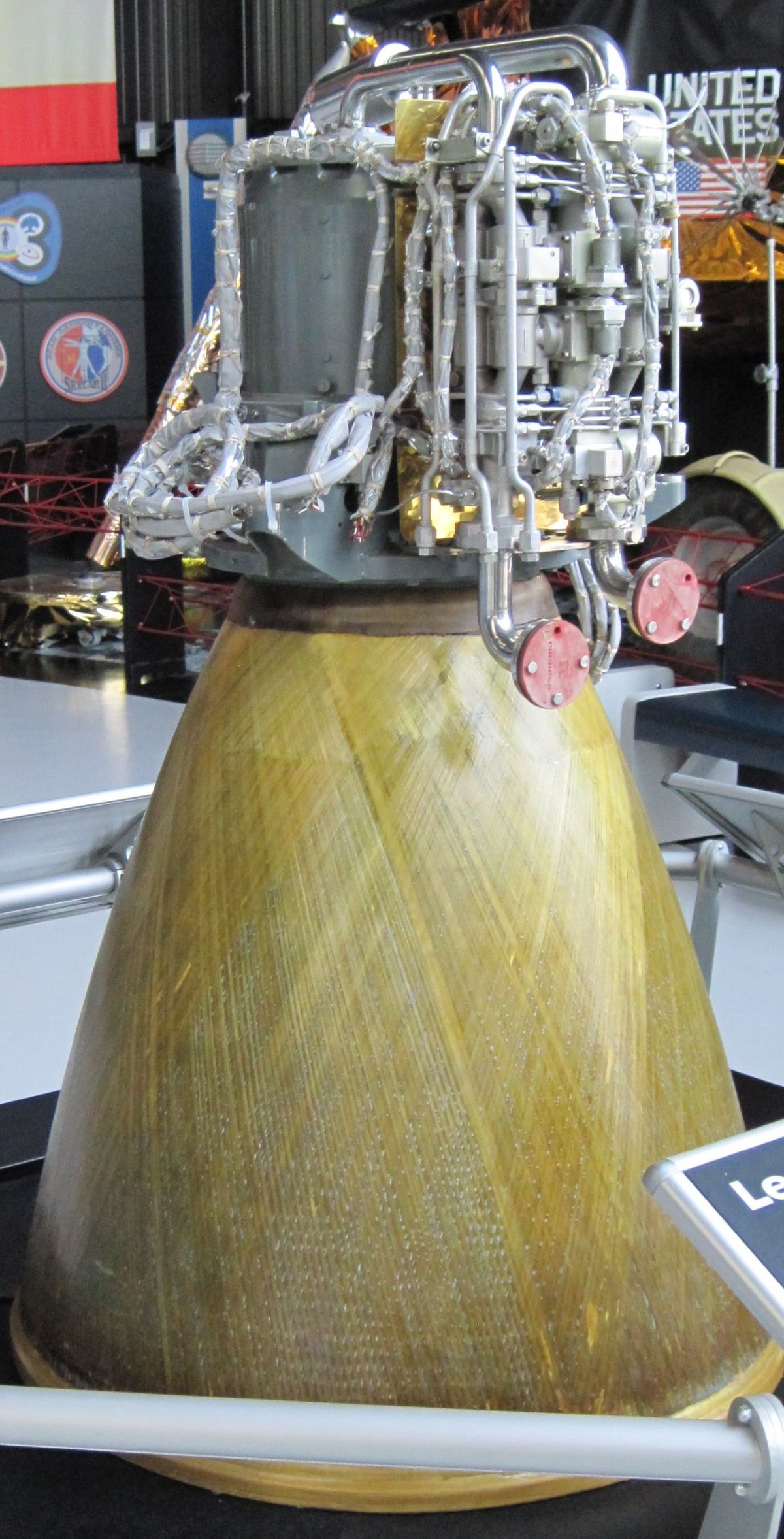
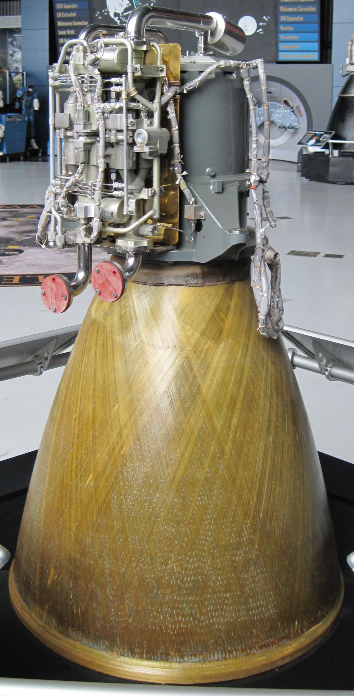
The Lunar Module Ascent Engine (LMAE, RS-1801) provided the astronauts' only escape from the lunar surface. Like so much Apollo/Saturn technology, the LMAE had to function nearly perfectly or people died. It was designed for simplicity and reliability, but even so, the development process was not easy. Both Bell Aerospace and Rocketdyne fought to eliminate LMAE combustion instability, conducting over 1,300 firing tests in the process. The tiny (3,500 lbT) engine lifted the > 10,500 lb (on earth) LM ascent stage from the earth's moon because lunar gravity was only 1/6 of earth. Like every other LM engine, the LMAE burned a hypergolic combination of nitrogen tetroxide oxidizer and Aerozine 50 fuel, a propellant combination selected for ultimate reliability. After all, American astronauts depended on one little engine to deliver them from the lunar surface to the CSM in lunar orbit. |
Introduction
|
The LMAE produced 3,500 lbT with a maximum allowable start-transient combustion chamber pressure of 177% over nominal (a LM structural limitation). To minimize heat transfer to the chamber, the magnitude of any periodic or uniformly cyclic chamber pressure fluctuation or oscillation that occurred at a frequency of 400 Hz or less could not exceed t 3 psi, and those variations that occurred at a frequency greater than 400 hertz could not exceed ±6 psi. In addition, the engine was required to be dynamically stable in the presence of all self-induced or artificially induced disturbances, thereby causing fluctuations of 175% of nominal chamber pressure in the combustion process. Recovery time to a stable steady-state operation could not exceed 0.030 second. Propellant bulk temperature was 70°F ±20°F, and the fuel and oxidizer temperatures had to be within 10°F of each other.
LMAE propellants were chosen based on experience with other programs, LM design commonality, storage requirements, hypergolicity, performance, and density. Pressure-fed engines decreased complexity by eliminating pumps, moving parts, and controls. Propellant tanks were pressurized by high-pressure gaseous helium stored at ambient temperature. Ablatively-cooled, as compared with regeneratively-cooled, thrust chambers decreased the possibility of propellants freezing. Wider mixture ratio, propellant temperature, and chamber pressure operational limits also were possible with ablatively cooled chambers. A highly-reliable, single-engine, non-gimbaled design concept simplified vehicle control system requirements and thereby increased total system reliability. Early studies showed that the majority of propulsion-system failures were caused by control, valve, and solenoid failures and not injector or thrust-chamber failures. Therefore, redundancy of the failure-prone components was used, where practical, to increase reliability.
LMAE Description
Combustion Chamber and Nozzle Extension
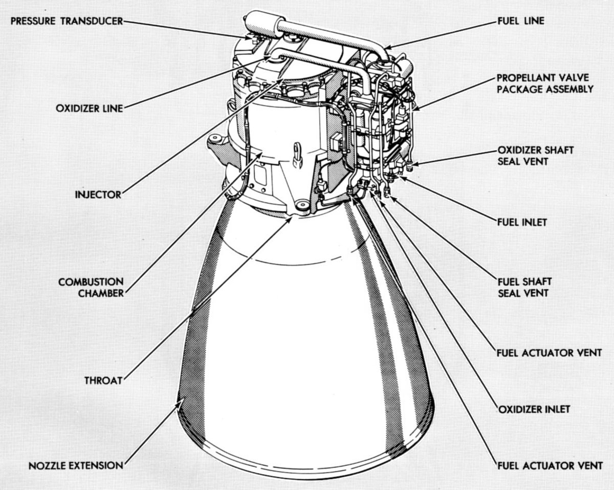
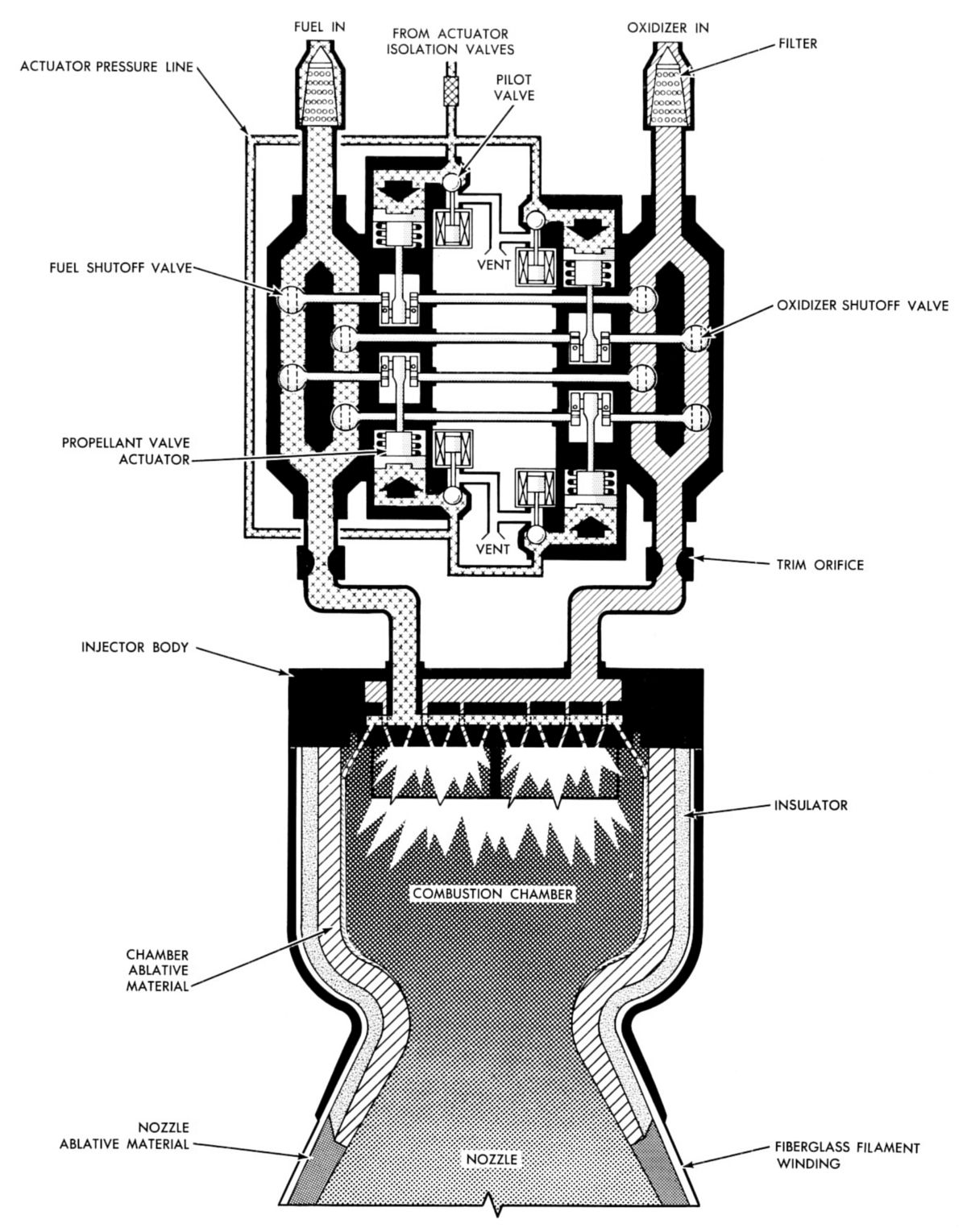
The combustion chamber assembly consisted of the engine case and mount assembly and an ablative material (plastic) assembly, which included the nozzle extension. The two assemblies were bonded and locked together to form an integral unit. The plastic assembly, which provided ablative cooling for the combustion chamber, consisted of the chamber ablative material, the chamber insulator, the nozzle extension ablative material, and a structural filament winding. The chamber ablative material extended from the injector down to the location of expansion ratio 4.6:1. The chamber insulator, between the ablative material and the case, maintained the chamber skin temperature within design limits. The nozzle extension ablative material extended from the expansion ratio of 4.5:1 to the 45.6:1 exit plane and provided ablative cooling in this region. The structural fiberglass filament winding provided structural support for the plastic assembly and tied the chamber and nozzle extension sections together.
Bipropellant Valve Package
Oxidizer and fuel lines entered the bipropellant valve package at the engine assembly interface. The four individual bipropellant valve assemblies that made up the bipropellant valve package were arranged in a series-parallel arrangement, which provided redundant propellant flow start and stop capability. Each valve assembly consisted of one fuel shutoff ball valve and one oxidizer shutoff ball valve, both rotating on a common shaft connected to its respective pilot valve and actuator. Shaft seals and vented cavities prevented propellants from contacting one other. Separate overboard vent manifold assemblies drained any propellants that leaked past the valve seals, and the actuating fuel in the actuators when the pilot valves closed overboard. The eight shutoff valves opened and closed simultaneously and were controlled by four non-latching, solenoid-operated pilot valves that admitted actuation fluid to the actuators.
 |
 |
|
 |
 |
| Components | Flow Diagram | Walk-Around | ||
Injector Assembly
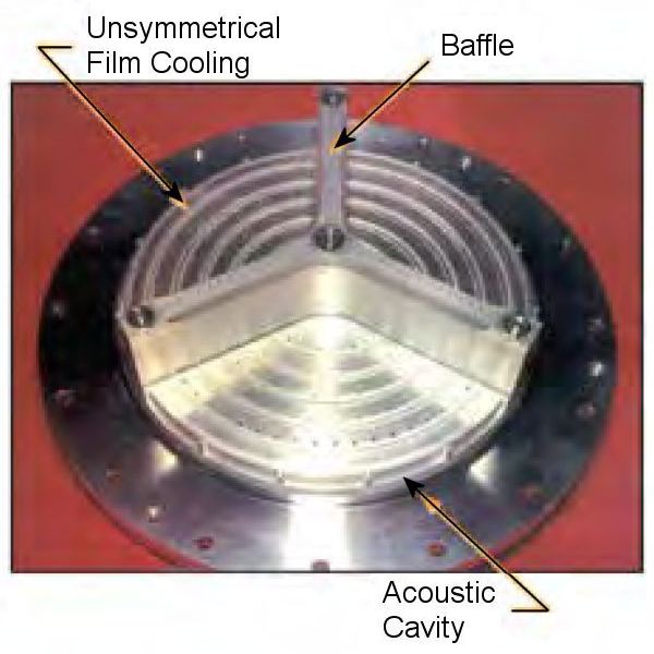
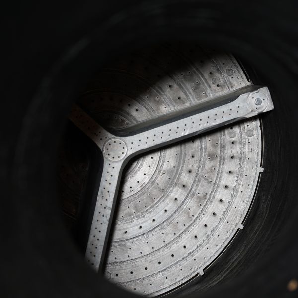
The injector assembly consisted of the propellant inlet lines, a fuel manifold, a fuel reservoir chamber, an oxidizer manifold, and an injector orifice plate assembly. Because it took longer to fill the fuel manifold and reservoir chamber assembly, oxidizer reached the combustion chamber about 50 milliseconds before the fuel, resulting in smooth engine starts (fuel-rich starts sometimes caused detonation). The fixed-orifice injector orifice plate assembly used a baffle and a series of perimeter slots (acoustic cavities) to damp combustion disturbances. The baffle was Y-shaped, with a 120° angle between blades, and was cooled by the propellants, which subsequently entered the combustion chamber through orifices on the baffle blades. The injector face was divided into primary and baffle combustion zones: The primary zone used impinging doublets (one fuel and one oxidizer), which were spaced in concentric radial rings on the injector face. The baffle zone (1.75" below the injector face) used impinging doublets placed at an angle to the injector face radius. The combustion chamber wall was cooled by spraying fuel against it through canted orifices, spaced around the injector perimeter.
Development
Grumman awarded the ascent engine development contract to Bell Aerosystems Company of Buffalo, New York in July 1963. NASA and Grumman thought Bell a good candidate because of its work on the XLR81 rocket engine that had powered the Lockheed RM-81 Agena as Atlas, Thor, Thorad and Titan booster upper stages. The development effort involved four tasks: the injector, the thrust chamber, the bipropellant valve, and the engine assembly.
Injector
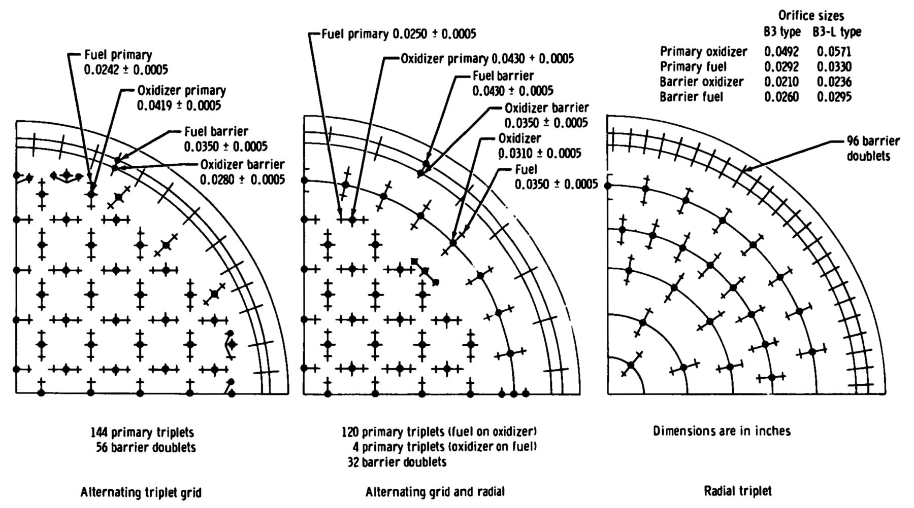 |
| Initial Prototype Injector Hole Patterns |
Bell released three prototype injector patterns for fabrication: an alternating-triplet grid pattern, an alternating-triplet grid and radial patterns, and a radial-triplet pattern. All three used a barrier doublet (oxidizer and fuel) for chamber cooling. In the summer of 1964, the radial-triplet pattern injector was selected for the further development because of its characteristic compatibility with the ablatively cooled thrust chamber. The injector pattern was soon modified to increase the film-barrier propellant-mixture ratio to achieve higher performance and still maintain thrust-chamber compatibility.
In Fall 1964, the NASA Manned Spacecraft Center (MSC) clarified combustion-stability criteria and increased the continuous burn time to 460 seconds because of increased LM weight. The combustion-stability criteria was a completely new requirement. Combustion-stability tests on the unbaffled injector were delayed because of an instrumentation shortage. In late January 1965, the unbaffled injector was determined to be unstable under the new criteria and a baffled configuration was proposed.
Bell investigated several baffle configurations. Using experience from the descent-engine program, a baffle with flow-through cooling was selected despite several combustion instability events during chamber bomb testing. Bell blamed the events on hardware failures, a test-bomb unrealistically located in the thrust chamber throat and a gap between the baffle and chamber. Bell hypothesized that an ablatively cooled chamber would help damp combustion oscillations. Two baffled injector versions were designed but fabrication problems introduced a 6-7 month delay. In order to meet schedules Bell released both injector designs for production before either was hot-fired.
The production injector eroded the ablative chamber material near the injector-chamber interface during its first firing. Bell modified the barrier orifices, which reduced but did not eliminate erosion. During engine qualification oxidizer- and fuel-calibration runs, combustion instability arose when the ablatively-cooled chamber was bomb-tested. The engine was inadvertently allowed to continue firing in this unstable mode until extensive injector damage occurred, making it impossible to determine whether the hardware was defective before instability or whether the instability caused the hardware damage. It was erroneously concluded that the instabilities resulted from hardware failure.
Bell hatched a plan to investigate the engine's ability to stably withstand combustion disturbances and to characterize the instabilities that did occur. However, a hardware shortage slowed the plan's progress. When combustion instability occurred in an ablatively-cooled chamber bomb test, NASA concluded that the injector was unsatisfactory. Later, a spontaneous instability occurred 290 seconds into an acceptance firing, further illustrating that the unsatisfactory injector design. Bell made numerous injector modifications in its attempt make it stable, but it took a second contractor to truly solve the problem.
NASA realized it had a problem with LMAE stability and in June 1967 put out a Request for Proposals for a contractor that could provide a stable backup injector system, engine qualification and engine final assembly. A proposal submitted by the Rocketdyne Division of North American Rockwell, Canoga Park, California, was highly focused on stability, as well as a superior baffle design. The Rocketdyne injector was to be compatible with other Bell-developed engine components. MSC and Grumman would manage the Rocketdyne contract, which involved the design, development, and qualification of a LM ascent engine. Rocketdyne offered the best manufacturing, with electron beam welding and electrical discharge machining (EDM) for injector orifice drilling.
Rocketdyne had developed an internally funded small rocket engine around 1965 that featured an annular gap between the injector and chamber wall. This was done to accommodate the different expansion ratios of the stainless steel injector and beryllium thrust chamber, but it serendipitously improved combustion stability. Rocketdyne used very short walls to break up the annular gap into segments, which were then dubbed acoustic cavities. Engineers didn't really know why the acoustic cavities improved stability, so Rocketdyne management insisted upon analysis, which revealed that the acoustic cavities formed a Helmholtz resonator that disrupted instability. Rocketdyne included this concept in its proposal, which helped sell the program to NASA. Rocketdyne submitted its proposal in June 1967 and, expecting to win, immediately started building hardware. The contract was awarded in July 1967, the go-ahead received in August, and the first injector test on 7 Sep 1967. System qualification testing was completed on 11 Jul 1968 and Rocketdyne got the overall LMAE contract on 28 Sep 1968, completing in just over a year what Bell had been unable to accomplish in four.
Rocketdyne's new injector design was a baffled, flat-faced, multi-ring unit with integral propellant-distribution manifolding and acoustic cavities. Three candidate injector orifice patterns included a triplet, consisting of two fuel streams impinging on each oxidizer stream; an unlike doublet, in which a stream of oxidizer impinged on each fuel stream; and a mixed doublet, in which the oxidizer/fuel mixing was a secondary result of fuel-fuel and oxidizer-oxidizer impingement. The unlike doublet was selected for production because of its performance, compatibility, and stability margins. Minor changes to the fuel-film cooling in the unlike-doublet injector design optimized performance and ablative compatibility while maintaining a wide combustion stability margin.
During bomb testing a combustion instability resulted in severe injector face damage; a "soft center" modification that closed off six of the nine impingement sets at the injector center reduced the central charge density and propellant availability for destructive radial combustion waves.
 |
 |
| Stand-Alone | Inside Engine (heriocrelics.org) |
The final injector design incorporated a woven-wire-cloth inlet filter screen that protected the injector orifices from contamination by stopping all particles. However, the filter's contaminant-capacity was not consistent with propellant tank's potential contaminant levels, which led to a more efficient caged inlet filter screen with a lower contaminated pressure drop for lunar-landing vehicles.
Tim Harmon had been with Rocketdyne only four years when the LMAE opportunity came along. He not only led the grueling LMAE test program, but went on to 10 other engine development campaigns, including CM attitude control engines, before his retirement after 41 years.
Rocketdyne realized that to rapidly fix the injector its program had to be an integrated effort based around a team consisting of engineering, development engineering, design, inspection, test engineering and quality personnel, along with NASA and Grumman. The team worked 24/7 to meet the schedule. Rocketdyne's Tim Harmon was in charge of stability testing and his group had two shifts of stability testers and a third shift to clean up the mess and prepare for the next day. In order to prove the design's feasibility, 12 injectors were built and subjected to 872 tests, which included 302 combustion stability tests and 23,078 seconds test time. The design verification program included 4 engine systems, environmental tests, 209 hot-fire tests and 5,706 seconds test time. Qualification testing included 6 engine systems, 308 hot-fire tests and 14,787 seconds test time.
Another program issue was combustion chamber erosion, which was typically solved by using some of the fuel for film cooling of the thrust chamber wall. However, this approach hurt performance. Rocketdyne discovered the ablative thrust chamber erosion was always in the same area and very cleverly reserved the film cooling for only that area.
Once the engine was working, NASA wanted to reduce its weight so that more moon rocks could be brought home. Tim Harmon's team reduced the 171-lb engine's weight by 30 lb, a very significant 15% reduction.
According to Harmon, Bell was a great help pushing the LMAE forward; Rocketdyne was responsible for the injector and final assembly but Bell had the valves and thrust chamber. The Bell development team suffered from the lack of instrumentation and test facilities, which had led to some blind alleys. Rocketdyne, a much larger organization, was able to commit significantly more resources to problem solving.
The Bell/Rocketdyne LMAE performed flawlessly during six lunar landings, as well as numerous other times during space flight testing.
Ablatively Cooled Thrust Chamber
The original ascent engine design called for an ablative thrust chamber and a radiation-cooled nozzle. The radiation-cooled nozzle had been demonstrated as technically feasible, but had never been applied to an engine buried in a vehicle or with fire-in-the-hole (FITH) starts from another stage (using the descent stage as a launch platform). Despite being heavier than the radiation-cooled ascent engine nozzle, an ablatively cooled nozzle eliminated the high design risk, high cost, lack of buried installation development experience, and test facility modifications.
Bipropellant Valve
The bipropellant-valve was a series-parallel hydraulically actuated ball valve arrangement with an electrical solenoid pilot valve. Although valve-level development testing was satisfactory, engine-level qualification testing to certify the valve for LM-1 revealed out-of-specification valve actuator leakage. The leakage was acceptable for unmanned flights, but design changes would be required for manned flight vehicles.
When the bipropellant valves were exposed to oxidizer vapors long-term, their needle bearings corroded, resulting in a change to stainless steel needle bearings. The fuel actuators leaked because of O-ring twisting during valve operation. Several valves on production engines at the backup-engine contractor plant were rejected. It was subsequently determined that the original leakage requirements were too stringent and that the valves were satisfactory under more realistic requirements.
Engine Assembly
Analyses of the heat-shield structural margins during fire-in-the-hole engine testing indicated a negative margin because of combustion-chamber-pressure peaks during the engine start transient. Bell investigated reducing the chamber-pressure overshoot without changing the valve design, but all solutions were unsuccessful. The LM's heat-shield structure was modified to accommodate the chamber overshoot. Rocketdyne experienced similar problems.
Due to Bell's injector combustion stability and ablative compatibility issues, its engine-development program was divided into two phases. First came a test program to certify that the early engines, equipped with early production injectors, were acceptable for flight on the unmanned LM-1 and LM-2; second was a test program demonstrating sufficient engine stability for the manned LM-3 and subsequent vehicles.
The first phase consisted of one sea-level test engine, five altitude-test engines, and three altitude qualification test engines. This test program revealed ablatively cooled thrust-chamber erosion and leakage in the valve actuator. However, it was concluded from these tests that the engine was satisfactory for the unmanned vehicles.
The second phase engines employed electrical-discharge machining (EDM) in the injector orifice fabrication processes. An additional qualification engine and a sea-level engine were added to the test program. Thrust-chamber erosion was still observed during these tests. The occurrence of preignition pressure spikes during engine startup required a change in propellant ducting that ensured oxidizer would reach the combustion chamber before the fuel. Six production flight rocket-engine assemblies endured environmental and hot-firing qualification tests. Some bipropellant valves were reused due to a hardware shortage. Acceptance testing precipitated a welding procedure change to prevent fatigue cracks in the weld attaching the baffle base to the injector face. This change improved the injector so that it was declared capable of manned flight.
References
Apollo Operations Handbook, Block II Spacecraft, Volume 1: Spacecraft Description 5M2A-03-BLOCK II (Houston, Texas: Manned Spacecraft Center, 15 Oct 1969).
Brooks, Courtney G., James M. Grimwood, Loyd S. Swenson, Jr. Chariots for Apollo: A History of Manned Lunar Spacecraft NASA SP-4205 (Washington, DC: NASA, 1979).
Cherne, Jack M. Mechanical Design of the Lunar Module Descent Engine (Redondo Beach, California: TRW Systems, 1967).
Dressler, Gordon A., J. Martin Bauer TRW Pintle Engine Heritage and Performance Characteristics (Redondo Beach, California: TRW Inc., 2000
Fisher, Steven C. and Shamin A. Rahman, eds. Remembering the Giants: Apollo Rocket Propulsion Development (Washington, DC: NASA, 2009).
Hoagland, Richard. Apollo News Reference (Bethpage, New York: Public Affairs, Space, Grumman Aerospace Corporation, 1971).
Humphries, Clarence E. and Reuben E. Taylor Apollo Experience Report — Ascent Propulsion System TN D-7082 (Houston, Texas: NASA Manned Spacecraft Center Mar 1973).
Hammock Jr., William R., Eldon C. Currie and and Arlie E. Fisher. Apollo Experience Report — Descent Propulsion System TN D-7143 (Houston, Texas: NASA Manned Spacecraft Center, Mar 1973).
Interbartolo, Michael Apollo Lunar Module Propulsion Systems Overview JSC-17237-14 (Houston, Texas: NASA Johnson Space Center, 1 Jan 2009).
Lunar Module LM-10 through LM-14 Vehicle Familiarization Manual LMA790-2 (Bethpage, New York: Grumman, 1 Nov 1969).
Vaughan, Chester A., Robert Villemarette, Witalij Karakulko, Donald R. Blevins Apollo Experience Report — Lunar Module Reaction Control System TN D-6740 (Houston, Texas: Manned Spacecraft Center, Mar 1972).
--- On to Part 9.45, The Apollo Lunar Module Reaction Control System ---
Send mail to
![]() with questions or comments about this web site.
with questions or comments about this web site.
![]()