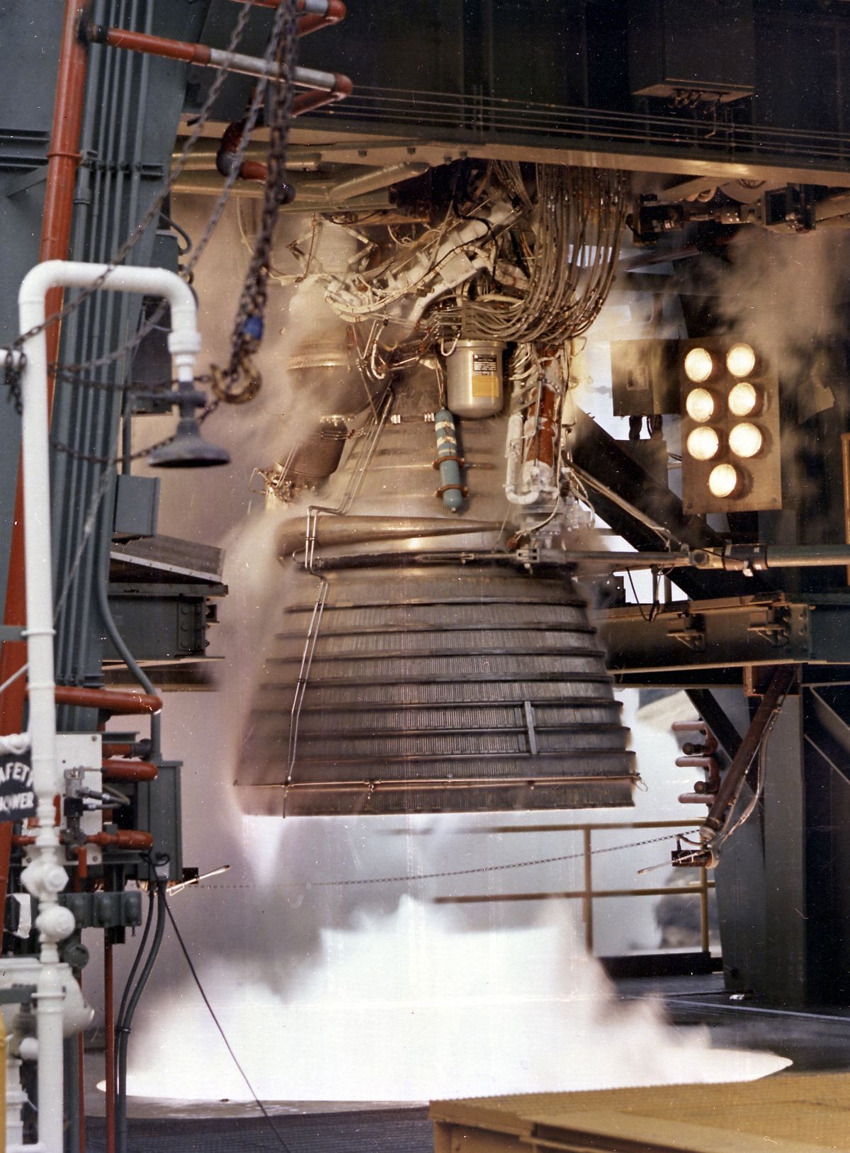
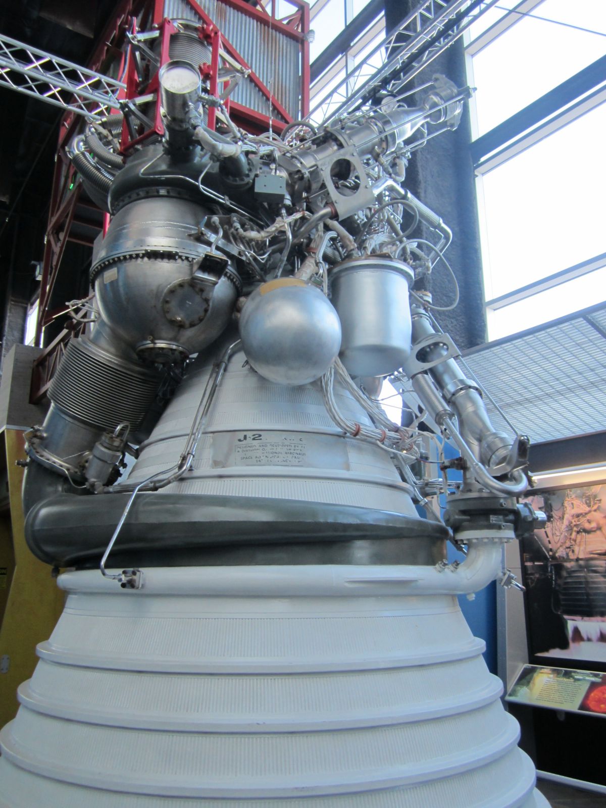
J-2 Under Test (Rocketdyne)
U.S. Manned Rocket Propulsion Evolution
Part 8.22: The Rocketdyne J-2 Engine
Compiled by Kimble D. McCutcheon
Published 1 Jul 2021; Revised 3 Aug 2022
J-2 Under Test (Rocketdyne) |
In a December 1959 Saturn Vehicle Team definition meeting chaired by Abe Silverstein and attended by ABMA, Air Force, NASA and the Office of Defense Research and Engineering representatives, Silverstein made a strong case for using the LH2/LOX combination for Saturn upper stages. Although Von Braun was initially resistant due to LH2’s finicky nature, he eventually warmed to the idea. LH2 in combination with LOX yields an extremely high specific impulse, but because LH2 is stored at -423°F its use requires considerable care. It must be stored in insulated containers and transported in insulated ducts; some metals when exposed to LH2's low temperature become brittle; LH2 liquefies air, which presents a whole new host of rocket design problems; LH2 is hard to contain, leaking through the smallest of seal and weld imperfections; hydrogen molecules soak into some metals and take up residence in the metal lattace, a phenomenon known as hydrogen embrittlement; hydrogen burns with a colorless flame, which inspired workers to carry brooms in front of them — if the broom caught fire there was a hydrogen fire. Rocketdyne addressed these problems and more to produce the very successful J-2. |
J-2 Background
Rocketdyne established its hydrogen bona fides starting in 1955 while working on the USAF's and U.S. Atomic Energy Commission's nuclear rocket propulsion program. A solid-core graphite-moderated reactor could reach a temperature of around 4,500°F; pumping LH2 over this hot core could theoretically produce specific impulse values that were more than twice as high as for burning LH2 with LOX. The USAF awarded Rocketdyne a contract to study pumping LH2. Starting with its Atlas MK3 turbopump Rocketdyne developed the MK9, a turbine-driven axial-flow LH2 pump that delivered 10,000 gpm at 1,500 psi. In addition, Rocketdyne developed a regeneratively-cooled nozzle using LH2 as the coolant. Although a prototype nuclear rocket was tested in the Nevada desert, the program was eventually abandoned. However, Rocketdyne had gained valuable insight into working with LH2.
In 1957, Rocketdyne's Advanced Design Group created a briefing extolling the virtues of LH2. Tom Dixon, Rocketdyne's Vice-President for Development, briefed anyone at the Pentagon that would stand still for 10 minutes, thus creating an interest in and customers for a LH2/LOX engine. Back at Canoga Park, Dixon started work on a 200,000 lbT engine. In October 1958, ARPA gave Pratt & Whitney a sole-source contract to develop the RL10 for the Centaur upper stage rocket; Rocketdyne was flabbergasted! P&W had never built any kind of rocket engine. It had, however, also built and tested LH2 pumps and nozzles for its Project Suntan work. Rocketdyne was so outraged at losing to P&W that it redoubled its LH2 engine efforts; this was to become the J-2, whose initial development proceeded with USAF funding. In 1960, MSFC took over J-2 development contract management from the Air Force and gave Rocketdyne a development contract on 1 Sep 1960.
To build the J-2, Rocketdyne upgraded the MK9 turbopump to the MK15, a 7-stage axial LH2 pump driven by a dedicated two-stage velocity-compounded turbine. The LOX turbopump was a more traditional centrifugal pump driven by a dedicated two-stage velocity-compounded turbine. A single gas generator directed its fuel-rich hot gas first to the fuel turbine; the fuel turbine's exhaust then drove the LOX turbine. The LOX turbine output exited into the exhaust nozzle at the 16:1 expansion point, thereby contributing slightly to the total thrust.
The J-2 was capable of being restarted in space. To achieve this, Rocketdyne introduced plumbing to refill the 4.2 ft³ start tank with high-pressure GH2 fresh from the thrust chamber cooling jacket. The start tank, which was initially filled from a ground supply, spun up the two pump turbines to a point the engine could be started and the rising pump output pressures became self-sustaining. A bypass valve connecting the LOX pump outlet to its inlet (propellant utilization valve) provided a degree of mixture and thrust control.
The J-2 first flew on 26 Feb 1966 as a Saturn 1B second stage, part of AS-201. This was the first full test of the unscrewed Apollo Command and Service Module, Saturn S-IVB stage and Saturn S-IB stage.
J-2 Development
J-2 development was relatively trouble free. Engineers learned that during start the valve actuation sequencing had to be carefully worked out to avoid LH2 pump cavitation. These kinds of start-up and cutoff sensitivities and transients are typical of most rocket engine development programs. The start and stop recipes must be developed by trial and error, but suitable schedules almost always evolve.
Rocketdyne engineers learned that problems with hydrogen embrittlement could be mitigated by plating parts with copper or gold, creating a dense coating that the hydrogen penetrated much more slowly than the native metal. They also developed special Teflon®-coated seals to keep hydrogen contained at duct flanges and pipe joints.
The original J-2 injector was a flat-faced copper affair similar to the concentric doublet and triplet injectors Rocketdyne had used in previous engines. Although there was no combustion instability with the LH2/LOX combination, heating patterns were significantly different. Injectors melted and the vaporized copper turned exhaust plumes green. MSFC suggested using the same injector scheme Pratt & Whitney had successfully applied to the RL10; naturally, Rocketdyne was reluctant to embrace a competitor's technology and green exhaust plumes persisted. Finally, in 1962 and at MSFC's insistence, Rocketdyne engineers traveled to NASA's Lewis Research Center in Cleveland, OH to see examples of the Lewis injector and RL10 Rigi-mesh injector. Rocketdyne designed a new injector based no these principles and the green flames disappeared.
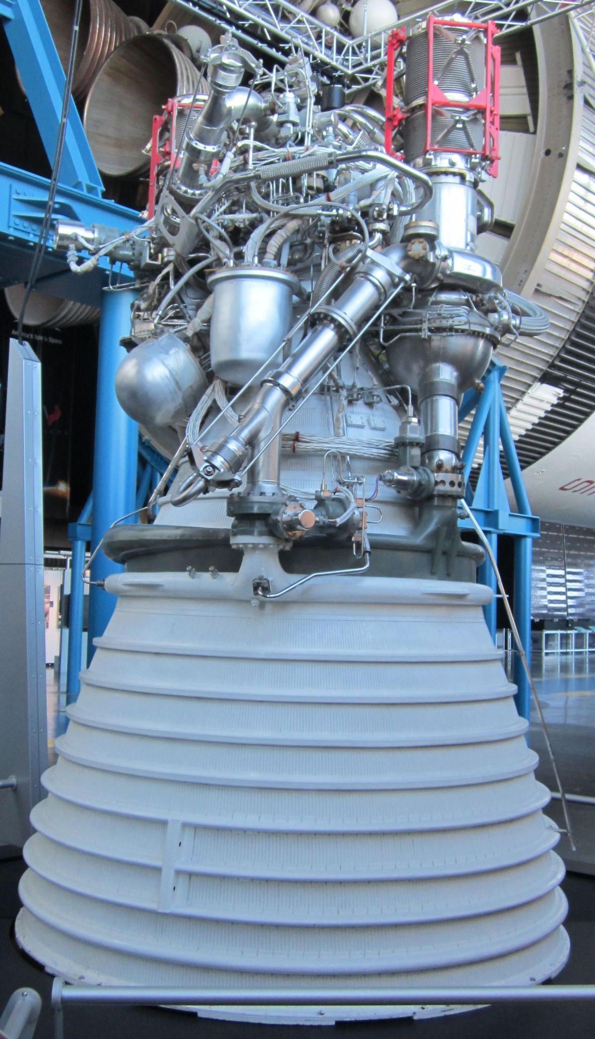
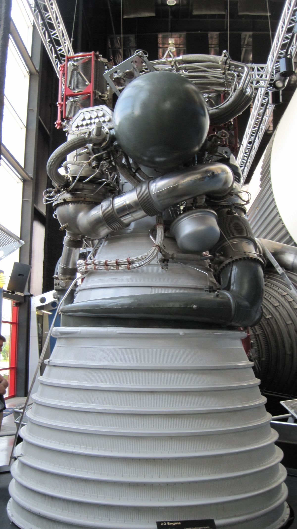
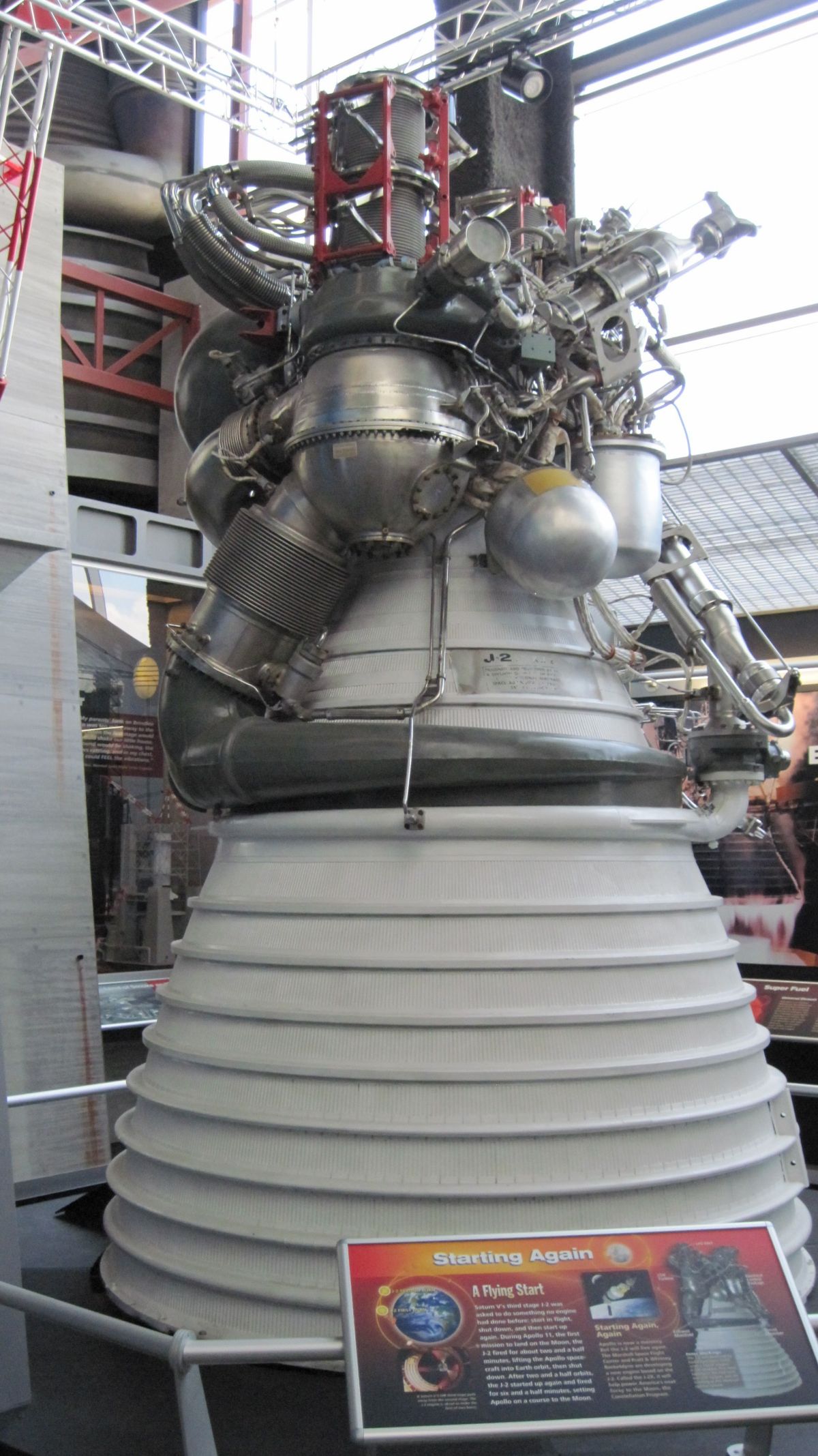
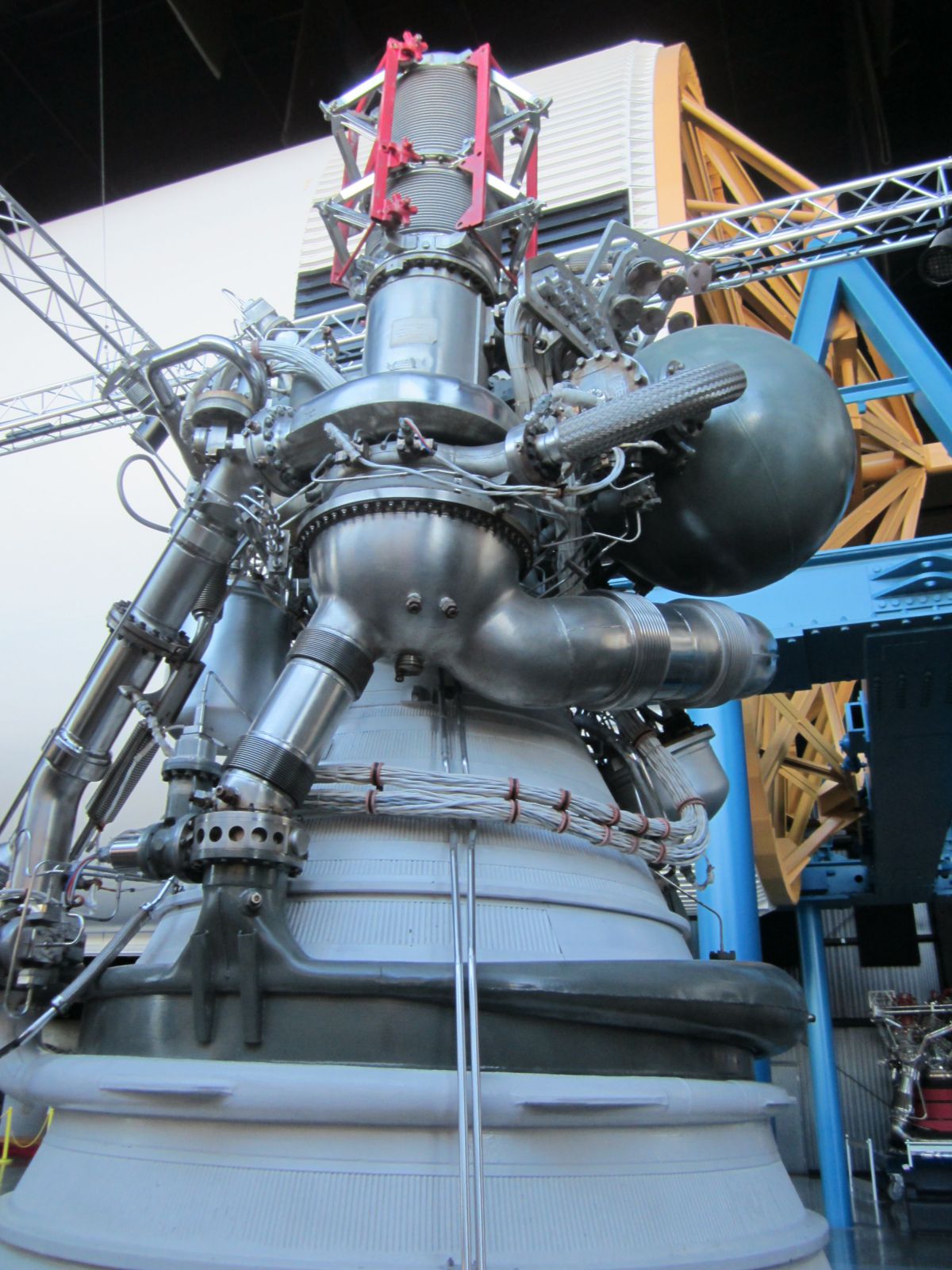
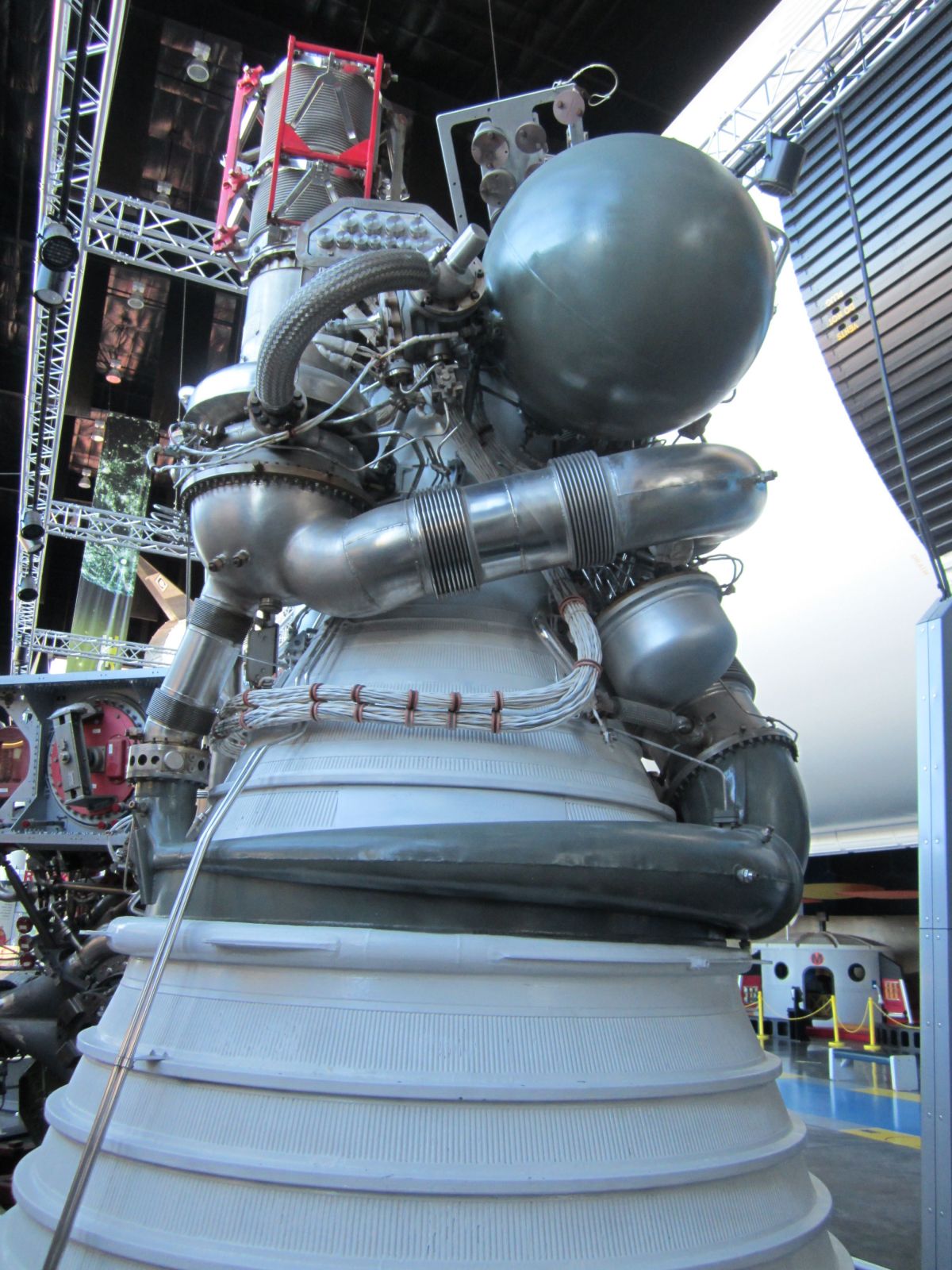
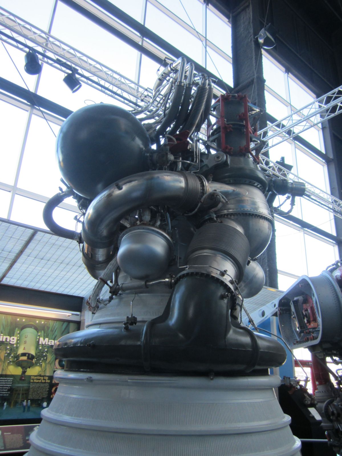
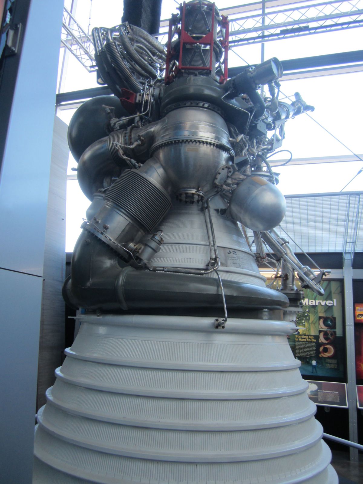
| Overall Views | |||
|---|---|---|---|
 |
 |
 |
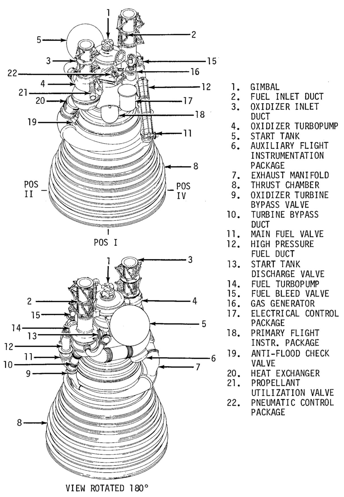 |
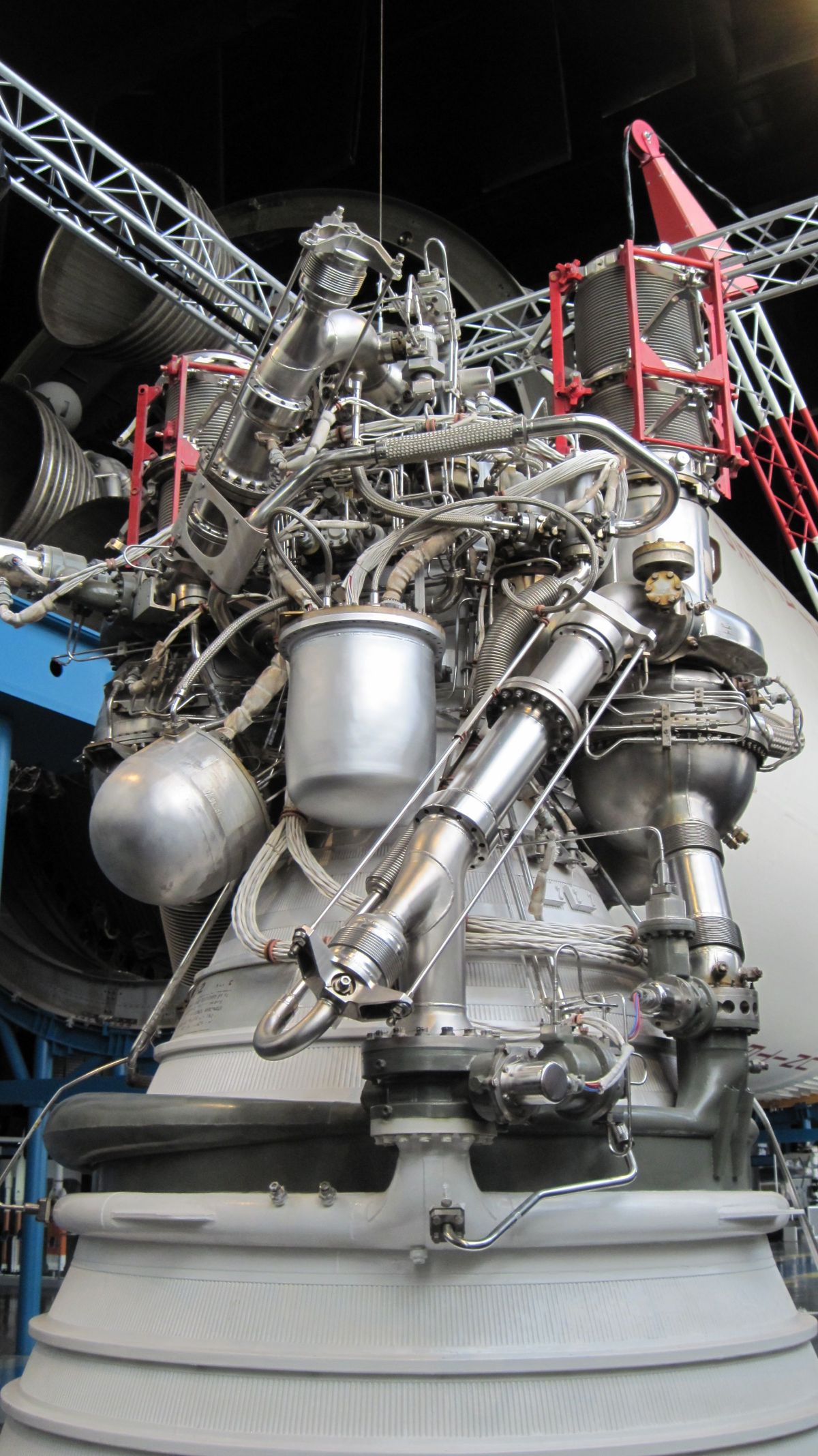
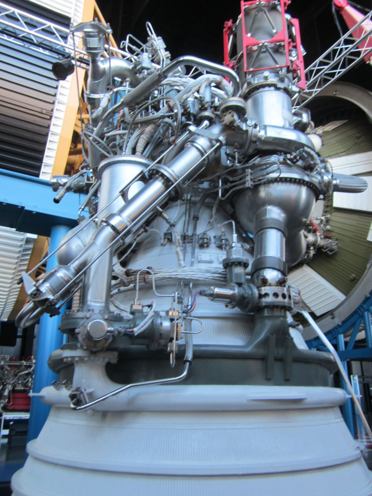
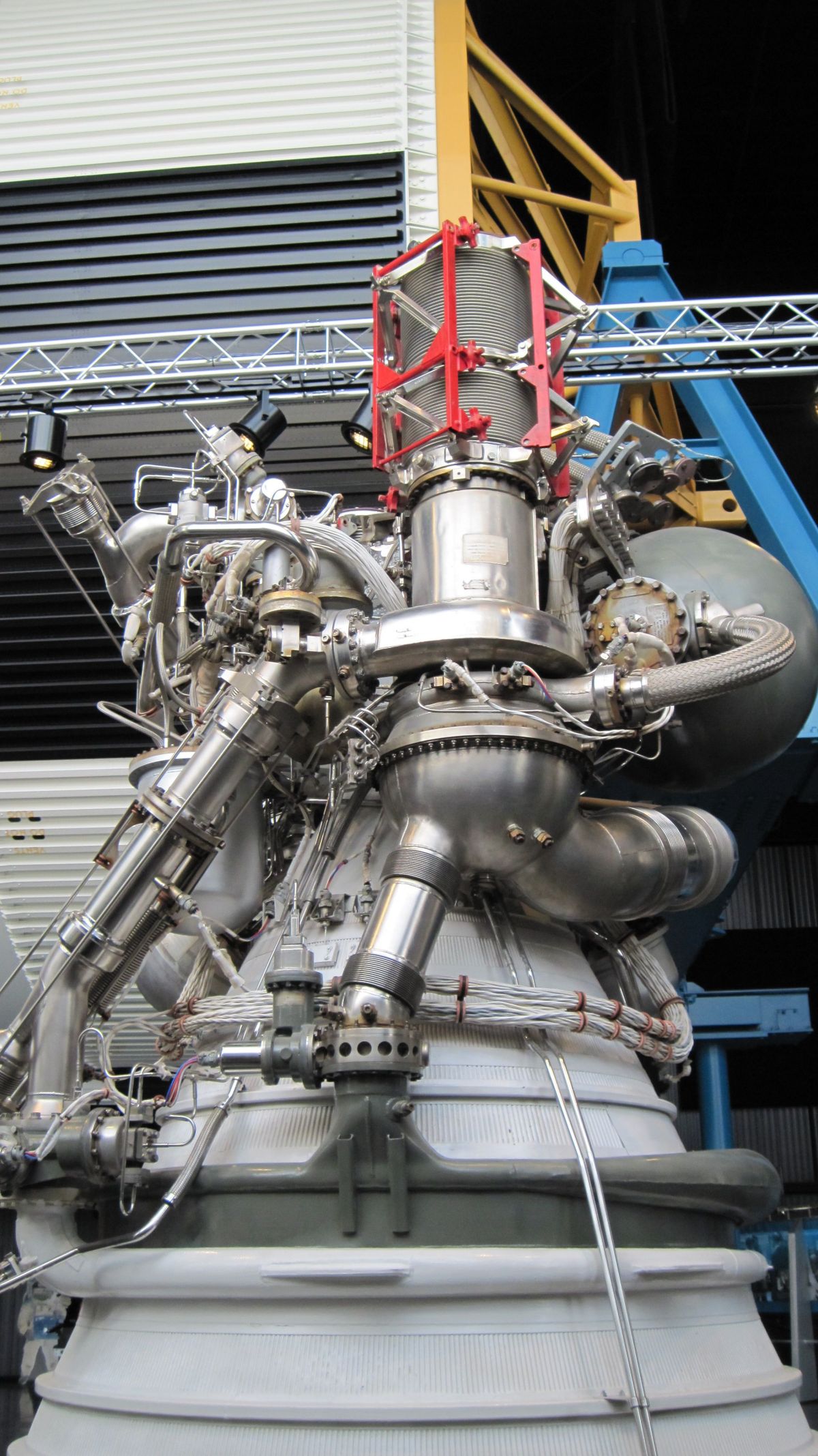
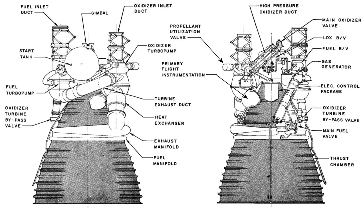
| Fuel Turbopump Side | Start Tank Side | Oxidizer Turbopump Side | Component Identification |
| Detailed Views | |||
 |
 |
 |
 |
 |
 |
 |
 |
Description
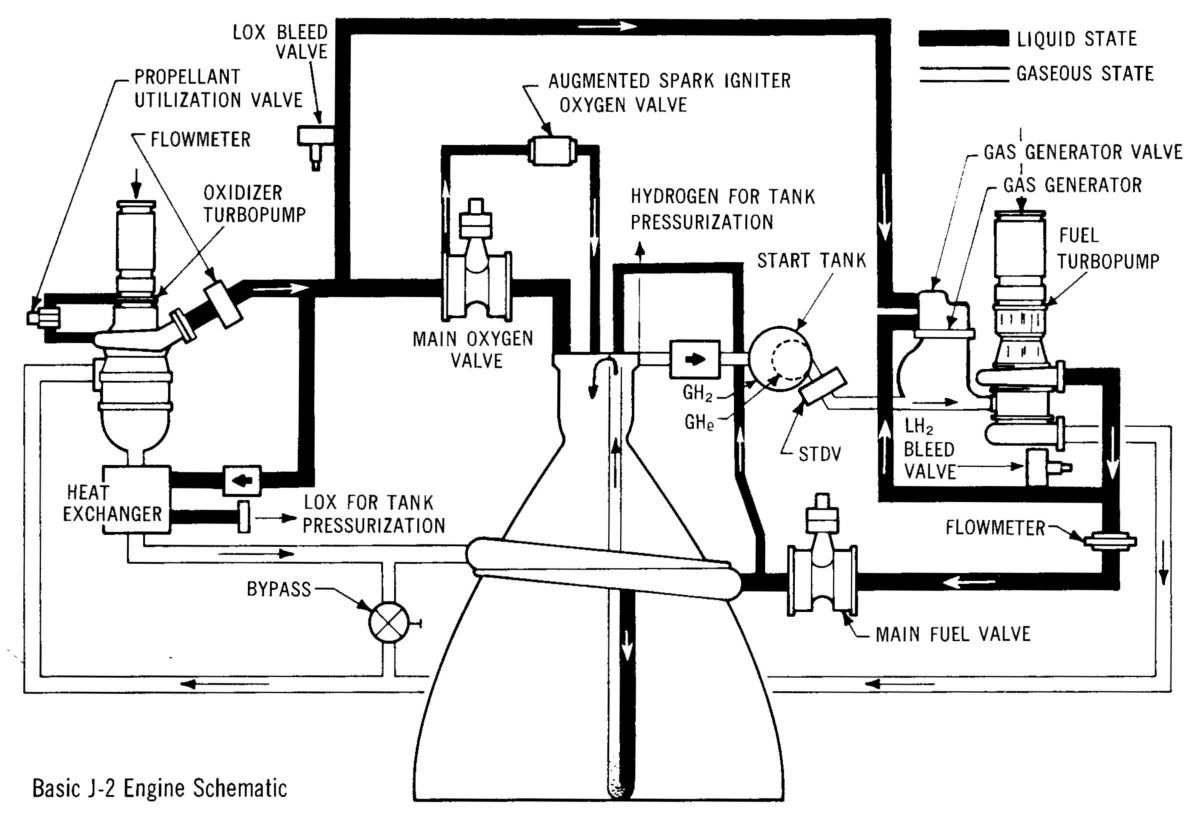
The J-2 rocket engine featured a bell-shaped thrust chamber, an injector, two direct-drive turbopumps, a gas generator, valves, engine-mounted electrical and pneumatic controls, and instrumentation. The initial fuel and oxidizer turbopump start impulse was delivered by an engine-mounted start tank pressurized with GH2. The nominal engine oxidizer/fuel ratio ranged from 4. 5 to 5. 5, depending on the propellant utilization valve position. A pneumatic control system used GHe supplied from a tank inside the start tank for engine valve operation. Engine-mounted electrical control packages provided the necessary logic for proper engine sequencing.
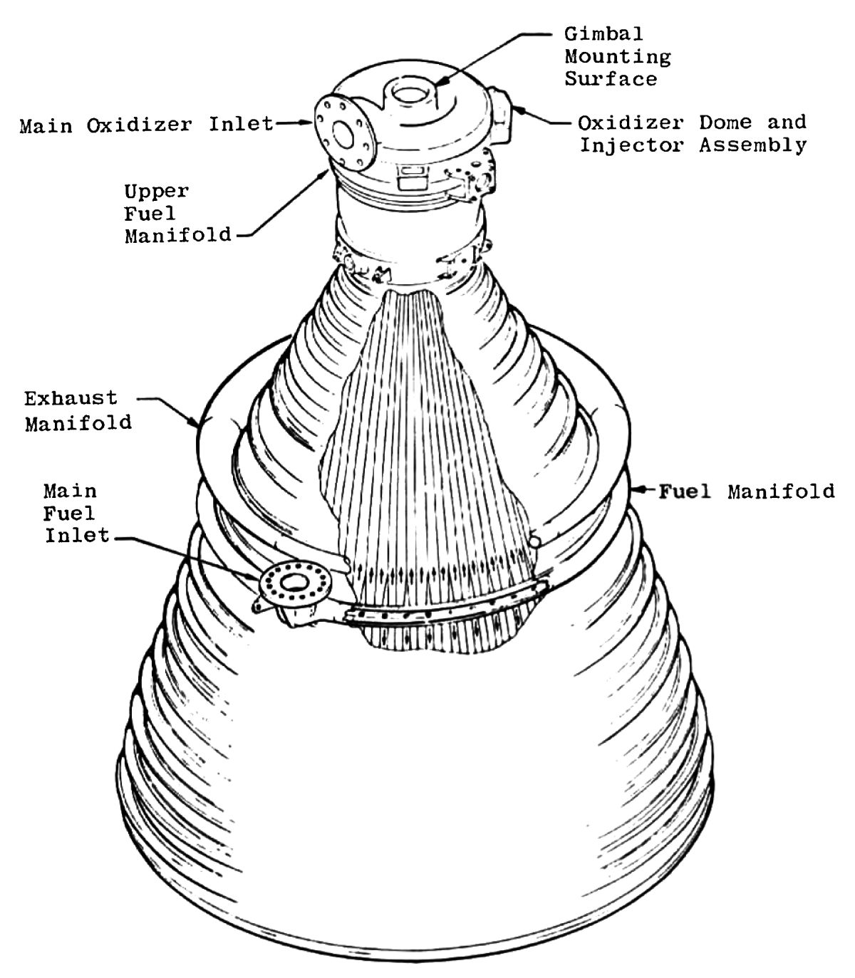
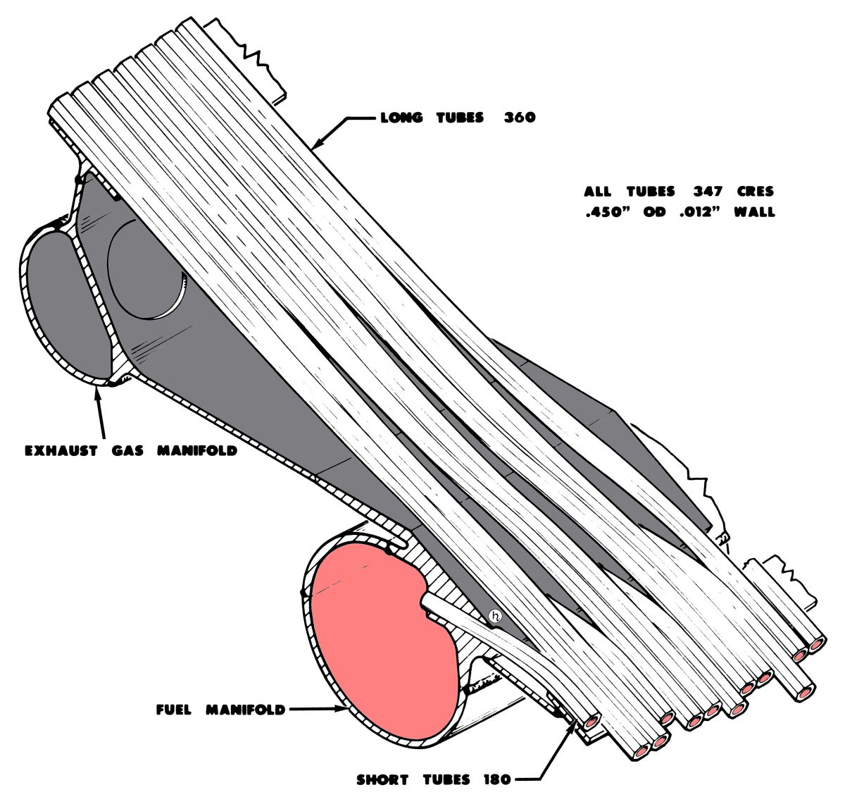
The tubular-walled, bell-shaped thrust chamber consisted of a cylindrical combustion chamber with a 170.4 in² throat area and a divergent nozzle with an expansion ratio of 27:1. The 18.6" diameter combustion chamber was 8.0" long from the injector mounting face to the throat inlet, and the characteristic length was 24.6". Overall thrust chamber length was 133" from the fuel pump low pressure duct inlet to the nozzle exit. The thrust chamber body was constructed of longitudinal stainless steel tubes that were brazed together and supported by external stiffening bands around the tubes. LH2 fuel from the fuel manifold circulated downward through 180 tubes, and back upward through 360 tubes to the thrust chamber injector, thereby cooling the thrust chamber.
 |
 |
 |
 |
| With Components Attached | Without Components | Exhaust and Fuel Manifolds (heriocrelics.org) |
Manifolds Interior Detail (heriocrelics.org) |
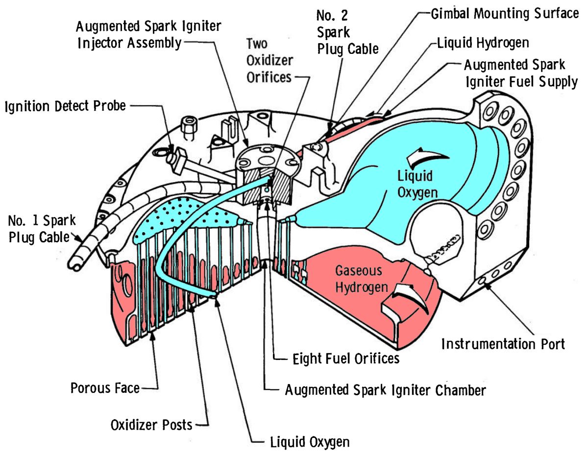
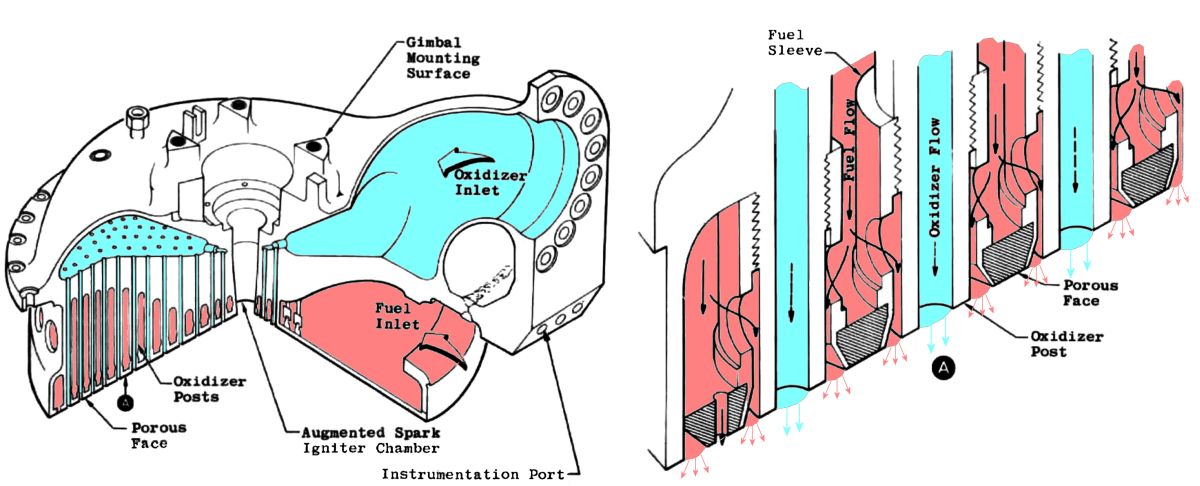 J-2 Injector |
The thrust chamber injector featured concentric fuel orifices around oxidizer post orifices embedded in a flattened conical porous-faced injector. Fuel and oxidizer injector orifice areas were 25.0 in² and 16.0 in², respectively. The porous sintered metal screen material (Rigi-Mesh®) that formed the injector face allowed 3 – 4% of the GH2 fuel to flow through and cool the injector face.
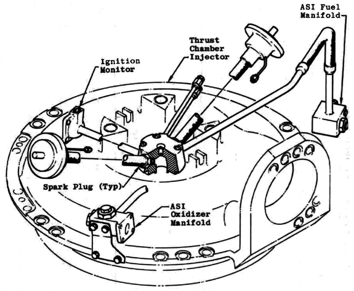 ASI Exterior |
 ASI Interior |
The augmented spark igniter (ASI) unit, mounted at the injector's center, ignited propellants in the main combustion chamber and remained operational for the engine's burn duration. The ASI chamber was an integral part of the injector. Fuel and oxidizer were routed to the ASI combustion area, where they were ignited by two energized spark plugs. A pneumatically operated poppet valve, mounted on the main oxidizer valve (MOV), controlled oxidizer flow to the ASI chamber.
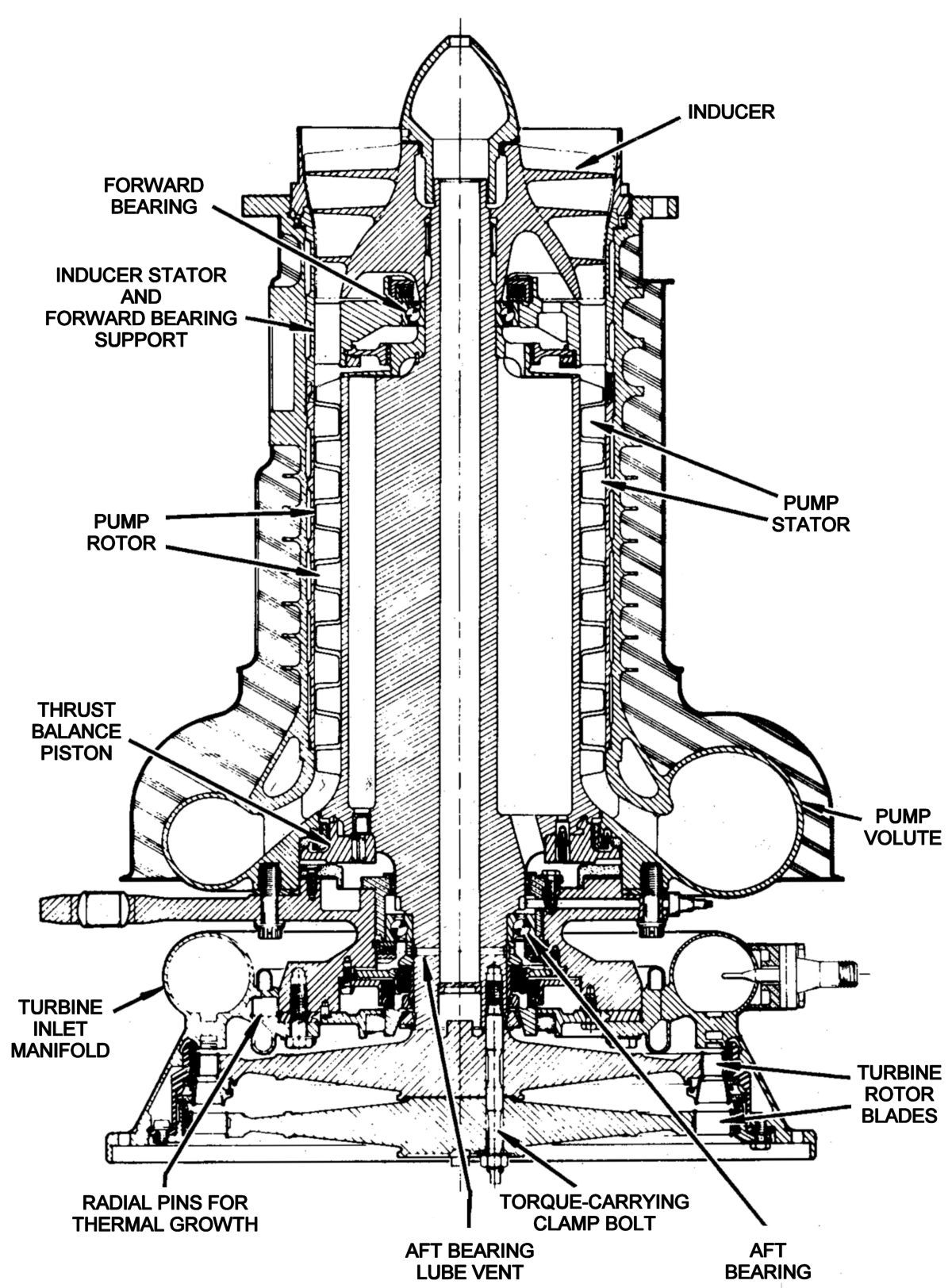
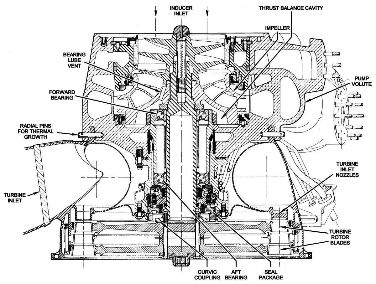
The self-lubricated high-speed axial-flow fuel turbopump, directly driven by a dedicated two-stage turbine, consisted of an inducer and a seven-stage rotor/stator assembly. A pressurized start tank supplied initial start energy to the turbine; a gas generator sustained the turbine during engine operation. The fuel and oxidizer turbines were gas coupled by an 8" diameter crossover duct that directed gases exiting the fuel turbine to the oxidizer turbine inlet. LH2 entered the turbopump through an 8.0" low pressure duct and exited through a 4.0" high pressure duct.
The oxidizer turbopump was a self-lubricated, high-speed, single-stage centrifugal pump with direct two-stage turbine drive. Gases discharged from the fuel turbopump turbine passed through the oxidizer turbine and exited through eyelets (total area of 115 in²) into the thrust chamber at area ratio stations 10.45 to 11.40. A percentage of fuel turbine exhaust gas volume was routed directly to the thrust chamber and bypassed the oxidizer turbine during the engine start transient to prevent turbine overspeed. When the MOV opened to its first stage, the bypass valve closed, and a greater volume of fuel turbine exhaust was directed to the oxidizer turbine. With the bypass valve closed, a nozzle in the valve bypassed a small percentage of gas and acted as a calibration device for turbopump performance balance and engine mixture ratio. LOX was supplied to the pump through an 8.0" low pressure duct and discharged through a 4.0" high pressure duct.
 |
 |
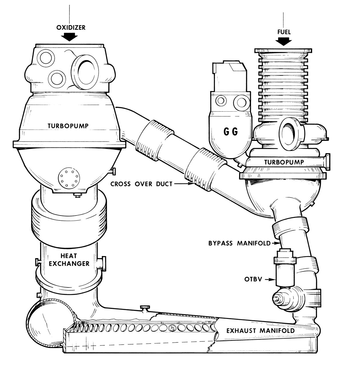 |
| J-2 Fuel Turbopump | J-2 Oxidizer Turbopump | J-2 Turbopump System (heriocrelics.org) |
The gas generator consisted of a combustion chamber containing two spark plugs, a pneumatically operated control valve housing oxidizer and fuel poppets, and an injector assembly. The oxidizer and fuel poppets were mechanically linked by an actuator and provided a fuel lead to the gas generator combustion chamber. Spark exciters in the electrical control package energized the spark plugs, which ignited propellants flowing into the gas generator. The gas generator outlet duct directed hot gases to the fuel and oxidizer turbines.
A spherical 7,258 in³ GH2 start tank with an internal spherical 1,000 in³ GHe tank was mounted on the engine. Pressurized GH2 in the fuel start tank provided spun the propellant turbines during engine start. GH2 for start tank repressurization during engine main-stage operation was obtained from the thrust chamber fuel manifold inlet and the fuel injection manifold. The GHe tank furnished high-pressure GHe to the engine control system. A pneumatic accumulator, filled from the GHe tank, provided GHe for an emergency shutdown if GHe tank pressure was lost during engine operation.
 Main Fuel Valve |
The main fuel valve (MFV) was a butterfly-type valve that was spring loaded to the closed position; it was pneumatically opened and its closing was pneumatically assisted. The MFV was mounted in the fuel high pressure duct between the fuel turbopump and the thrust chamber fuel manifold. A sequence valve mounted on the MFV controlled pneumatic pressure to the start tank discharge valve (STDV) solenoid control valve.
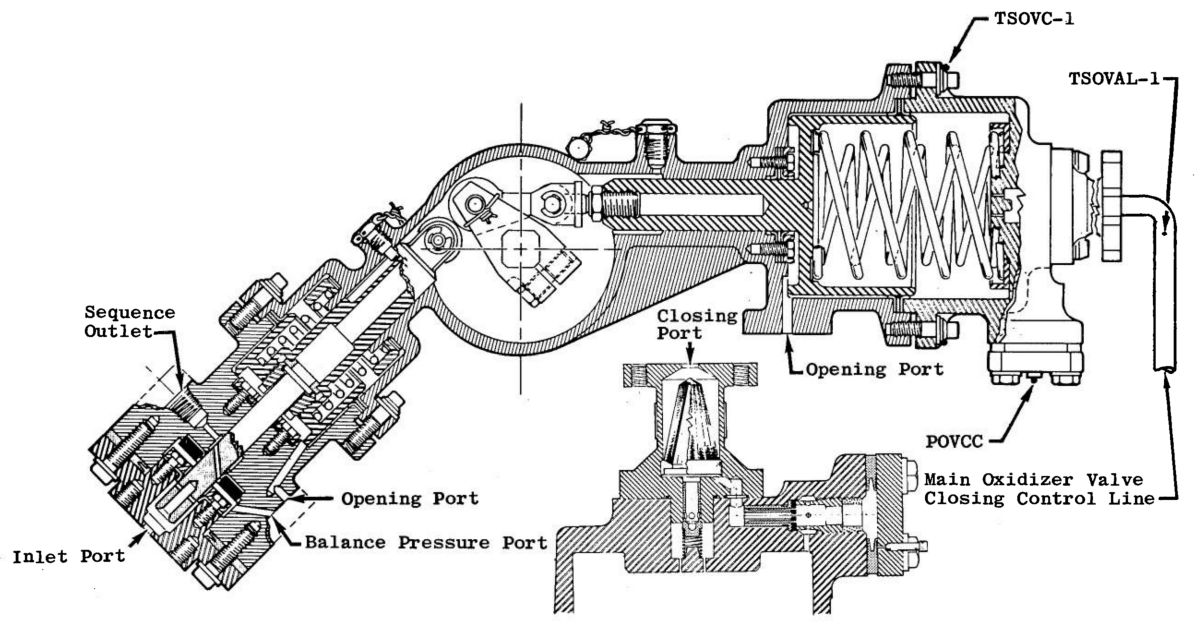 Main LOX Valve |
The MOV was a butterfly-type valve, spring loaded in the closed position, which opened in two stages. It was pneumatically opened and closed with pneumatic assistance. The MOV was mounted in the oxidizer high pressure duct between the oxidizer turbopump and the oxidizer injector manifold. A sequence valve on the MOV controlled pneumatic pressure to the gas generator control valve.
The electrically operated motor-driven propellant utilization valve bypassed a percentage of LOX from the oxidizer turbopump discharge to the pump inlet. Nominal mixture ratio range control with the PU valve was 4.5:1 (full open) to 5.5:1 (full closed) over an angle position change of 57°. The PU valve ensured simultaneous exhaustion of vehicle propellants. Propellant tank level sensors controlled the PU valve position for adjusting oxidizer flow.
An engine-mounted pneumatic control package managed all pneumatics required for pneumatically operated valves and engine-supplied purges. The pneumatic package controlled the MFV, first and second MOV stages, the oxidizer turbine bypass valve, the ASI oxidizer valve, purge control valve, and the fuel and oxidizer bleed valves. Purges of GHe to the main injector oxidizer dome and the gas generator oxidizer injector were also supplied from the pneumatic package.
An engine-mounted electrical control package sequenced engine components during operation. The electrical control package contained a sequence controller that properly sequenced engine start and shutdown, and a spark ignition system that energized the gas generator and ASI spark plugs.
Primary and auxiliary flight instrumentation packages contained sensors to monitor critical engine parameters and provided sensor environmental control.
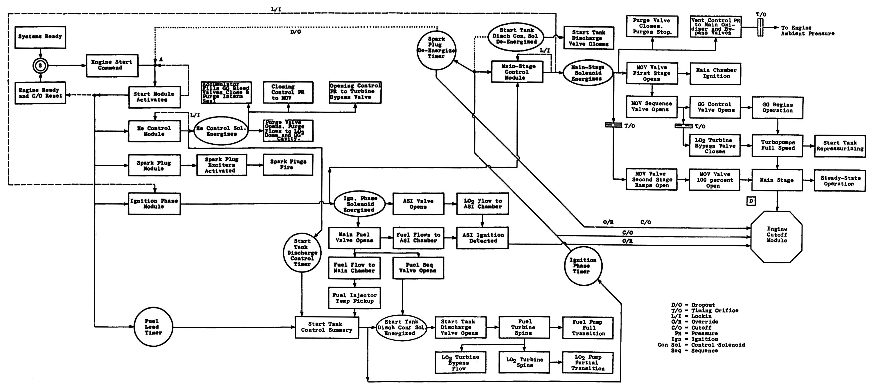 J-2 Start Logic |
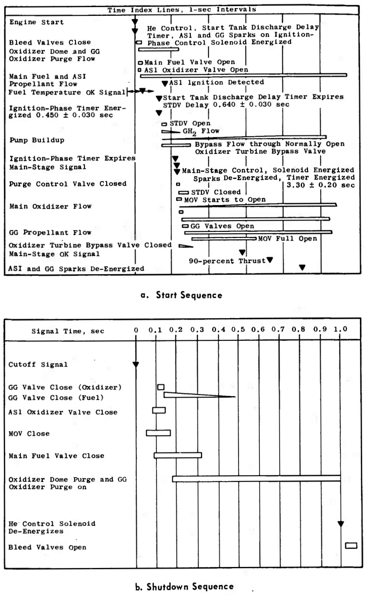 J-2 Start , Shutdown Sequence |
J-2 Operation
Start Preparations
The electrical control package controlled J-2 start and cutoff sequences. The IU issued an engine ready bypass signal just prior to an engine start attempt; this reset the electrical control package, arming it for a start command, which initiated the start sequence. Prior to engine start the IU would have checked the status of applicable engine components.
Start Sequence
The start command initiated operation of spark exciters in the electrical control package; these energized the gas generator and ASI spark plugs. The helium control and ignition phase control valves in the pneumatic control package were also energized, allowing helium to flow from the helium tank through the pneumatic regulator to the pneumatic control system. A check valve in the pneumatic control package ensured continued pressure to the engine valves if the helium supply failed. The regulated helium filled a pneumatic accumulator and closed the propellant bleed valves. The oxidizer turbopump intermediate seal cavity was continuously purged. The mainstage control valve held the main oxidizer valve closed and opened the purge control valve, which purged the oxidizer dome and GG oxidizer injector. The mainstage control valve also supplied opening control pressure to the oxidizer turbine bypass valve. The ignition phase control valve, when actuated, opened the MFV, the ASI oxidizer valve and supplied pressure to the sequence valve located in the MOV. LH2 was tapped downstream of the MFV for use in the ASI. Both LOX and LH2, under tank pressure, flowed through the stationary turbopumps.
The sequence valve in the MFV opened when the MFV reached approximately 90% open and routed helium to the start tank discharge valve (STDV) control valve. Simultaneous with engine start the STDV delay timer was energized. When it expired and the stage-supplied mainstage enable signal was received, the STDV control valve and ignition phase timer were energized. As the STDV control valve energized the discharge valve opened allowing pressurized GH2 to flow through the two turbopump turbines. Both turbopumps accelerated to proper operating levels, allowing subsequent ignition and GG power build up. An orifice in the oxidizer turbine bypass valve controlled the relationship of fuel to LOX turbopump speed buildup. During the start sequence the normally open oxidizer bypass valve bypassed a percentage of oxidizer turbine gas.
The ASI ignition monitor detected ASI combustion. If ignition was not detected or the start tank became depressurized, engine cutoff occurred when the ignition phase timer expired. If both signals were present at ignition phase timer expiration, the mainstage control valve energized. Simultaneously, the sparks de-energize timer was energized and the STDV control valve was de-energized, causing the STDV to close. Helium pressure was vented from the MOV and from the purge control valve through the mainstage control valve. The purge control valve closed terminating the oxidizer dome and GG oxidizer injector manifold purges. Pressure from the mainstage control valve was opened the MOV.
A sequence valve operated by the MOV routed GHe to open the GG control valve and to close the oxidizer turbine bypass valve. Flow to close the oxidizer turbine bypass valve was restricted as it passed through an orifice, which controlled the closing speed of this valve.
Propellants flowing into the GG were ignited by the energized sparkplugs. Propellant combustion yielded the hot gases that drove the turbopumps. The turbopump's rotation causes propellant pressure to build and the propellant flowing into the thrust chamber was ignited the ASI torch.
Transition into mainstage occurred as the turbopumps accelerated to steady-state speeds. Increasing oxidizer pump output pressure generated a thrust OK signal by either of the two thrust OK pressure switches, while cutoff occurred if no signal was received before the sparks de-energized timer expired. The ASI and GG sparks exciters were de-energized at expiration of the sparks de-energized timer. Cutoff occurred if both thrust OK pressure switch signals were lost during mainstage operation.
Steady-state engine operation was maintained until a stage-generated cutoff signal was received. During this period, GH2 from the fuel injection manifold pressurized the LH2 tank. LOX boiled by the turbine exhaust duct heat exchanger pressurized the LOX tank.
 |
 |
| J-2 Simplified Propellant Flow (heriocrelics.org) |
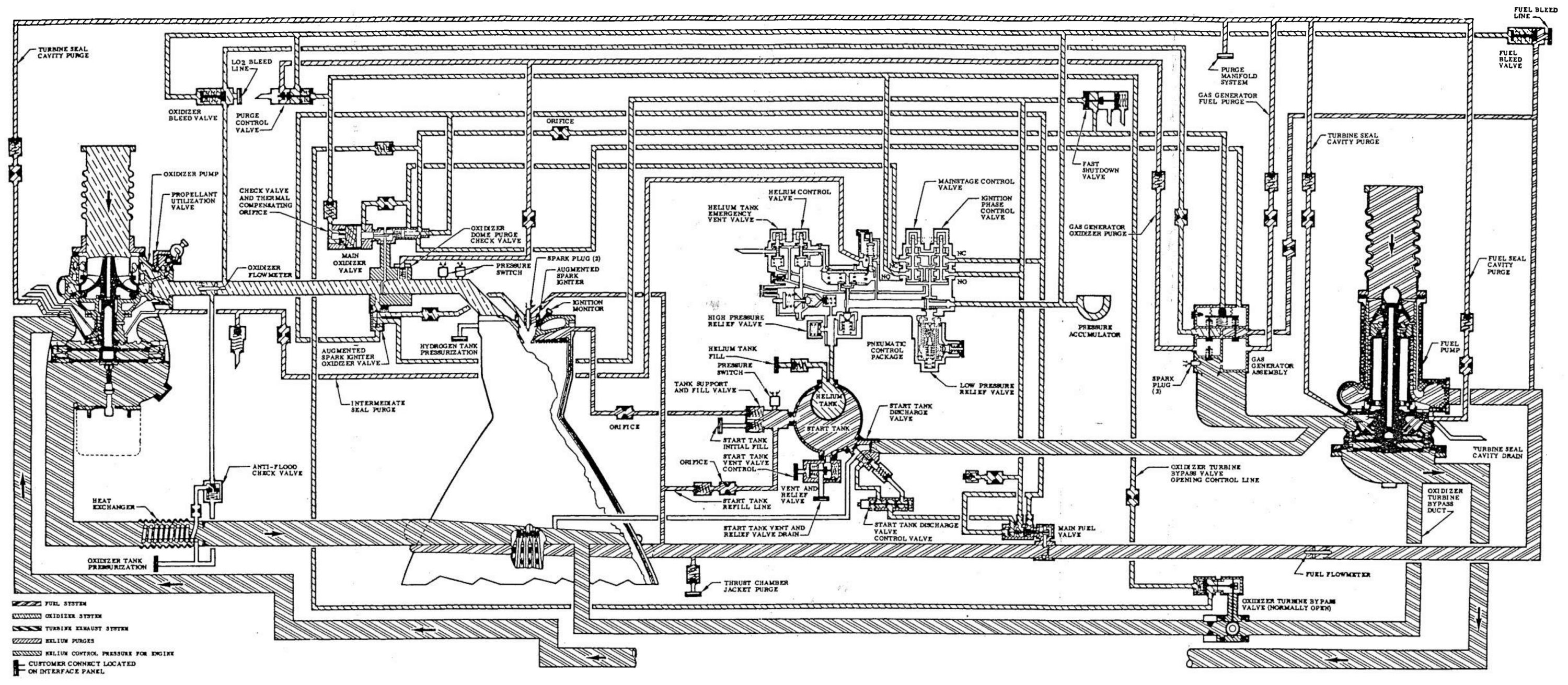
J-2 Expanded FLow Diagram |
Cutoff
A cutoff signal could originate from several different sources including engine interlock deviations, EDS automatic and manual aborts and propellant depletion. Each of these signals is processed the LVDC, which then sends the engine cutoff signal via the S-II stage switch selector to the electrical control package. The electrical control package controls the cutoff sequence.
Upon receipt of the cutoff signal the mainstage and ignition phase control valves in the pneumatic control package were de-energized, while the helium control de-energize timer was activated. The mainstage control valve closed the MOV and opened the purge control and oxidizer turbine bypass valves. The purge control valve routed a helium purge to the oxidizer dome and GG oxidizer injector. The ignition phase control valve closed the ASI oxidizer valve and MFV while opening the fast shutdown valve. The fast shutdown valve rapidly vented the GG control valve return flow. All valves except the ASI oxidizer valve and oxidizer turbine bypass valve were spring loaded closed. This caused the valves to start moving toward closed as soon as opening pressure was released. GG combustion also aided in closing of the GG control valve.
Expiration of the helium control de-energize timer caused the helium control valve close, stopping the oxidizer dome and GG oxidizer injector purges. An orifice in the locked up lines released pressure from the propellant bleed valves, allowing springs to open them and propellants to flow back to the propellant tanks.
Malfunction Detection
Each engine was capable of detecting malfunctions and to executing a safe shutdown. If neither mainstage OK pressure switch indicated sufficient thrust for mainstage operation before ignition phase timer expiration a shutdown was initiated. Once an engine transitioned to mainstage operation, it was shut down if both mainstage OK pressure switches deactuated due to a low thrust level.
The Troublesome SA-502 (Apollo 6)
By the time the uncrewed Saturn-Apollo 502 (SA-502, also called Apollo 6) was launched on 4 Apr 1968, four J-2 engines had powered S-IVB stages launched by Saturn 1B first-stage boosters (AS-201 through AS-204). Six additional J-2s had flown aboard the uncrewed SA-501 (Apollo 4) on 9 Nov 1967, which was the first all-up test of the Saturn V. All ten J-2 engines had performed nominally.
SA-502 was launched at 070001 EST. At about T+100 seconds, during the S-IC boost phase, a pogo oscillation developed that was about three times stronger than anything seen on SA-501; this oscillation persisted for about 40 seconds. S-IC cutoff at T+148.2 and S-II stage ignition at T+149.8 proceeded normally. At T+220 the No. 2 S-II engine instrumentation started to reflect a gradual temperature decrease, followed by a gradual performance decay. At T+319 No. 2 engine performance suddenly decreased and chamber pressure sensors recorded a 22.9 psia drop. This performance decay continued until T+413 when the launch vehicle's instrument unit (IU)commanded an engine No. 2 shutdown; engine No. 3 shutdown almost immediately – the shutdown signals between Nos. 2 and 3 had been switched! Sensing the No. 3 thrust reduction, the IU commanded No. 3 to shutdown, which finally killed No. 2. Now the rocket was running on three engines instead of five, a situation that had not been programmed into the IU's computer. The vehicle guidance computer nevertheless compensated for the two adjacent dead engines, commanded the remaining good engines to burn 58 seconds longer than planned and managed to achieve a lop-sided but acceptable orbit. S-II staging occurred at T+577, the spent S-II stage reentered the atmosphere and disintegrated. Some parts burned up, other heavier ones fell into the Atlantic Ocean west of the Canary Islands and sank.
The S-IVB third stage first burn established a more circular orbit, but also exhibited some problems. At T+645 the temperature of the single J-2 engine's external environment started to decrease, slowly at first and then much more rapidly at T+684; engine performance also started to degrade at that time. At T+696 the temperature trend reversed from cooling to heating. S-IVB engine cutoff occurred at T+747. After a two-orbit coast the IU issued a restart command for the second S-IVB burn at T+03:13:34.7; the engine did not restart.
The clever ground controllers separated the command and service modules (CSM) from the S-IVB and used the service module's (SM) service propulsion system engine (SPS) to achieve an orbit that resulted in high-speed command module (CM) reentry. Although the CM reentry was not as fast as planned, one of the key mission objectives of qualifying the CM heat shield for the highest-speed reentry yet attempted was met.
Two J-2 engines on two different stages had both failed and neither the Rocketdyne nor MSFC engineers had a clue why. Making matters worse, one stage was on the Atlantic ocean floor and the other was in low earth orbit, which meant the engineers had no way to examine the hardware for clues to the failures. There was, however, a lot of telemetry data for the engineers to pore through. Paul Castenholz, Rocketdyne's J-2 Program Manager, put everyone on a 24-hour schedule, and along with the MSFC team carefully examined this data for anomalies. When one was found they developed a set of hypotheses to explain it, and picked the hypothesis that was most closely supported by the data. In both the S-II and S-IVB the ASI was implicated.
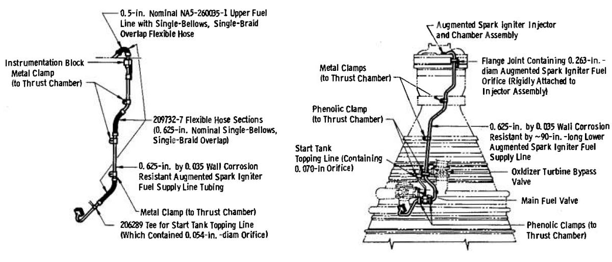
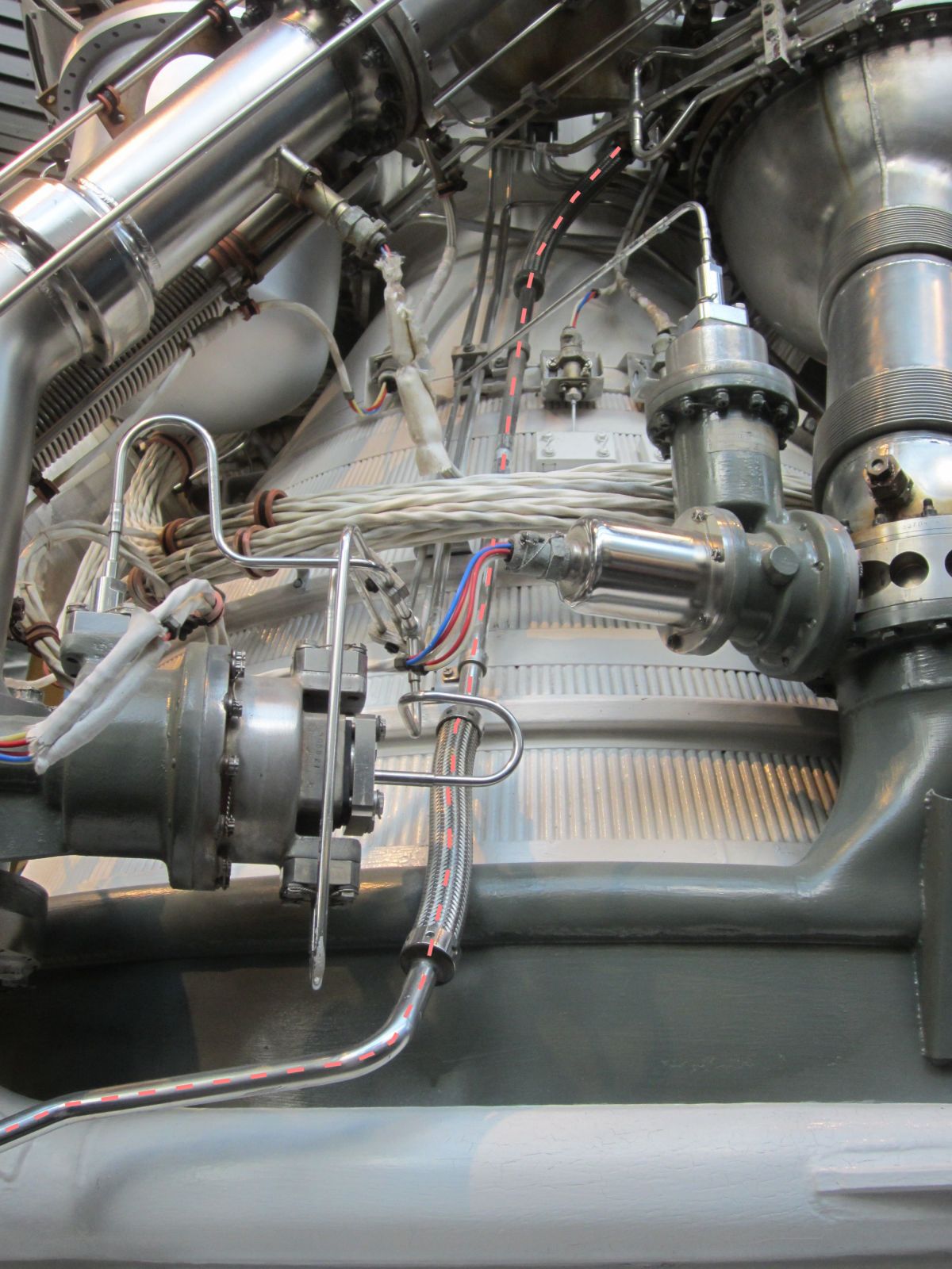
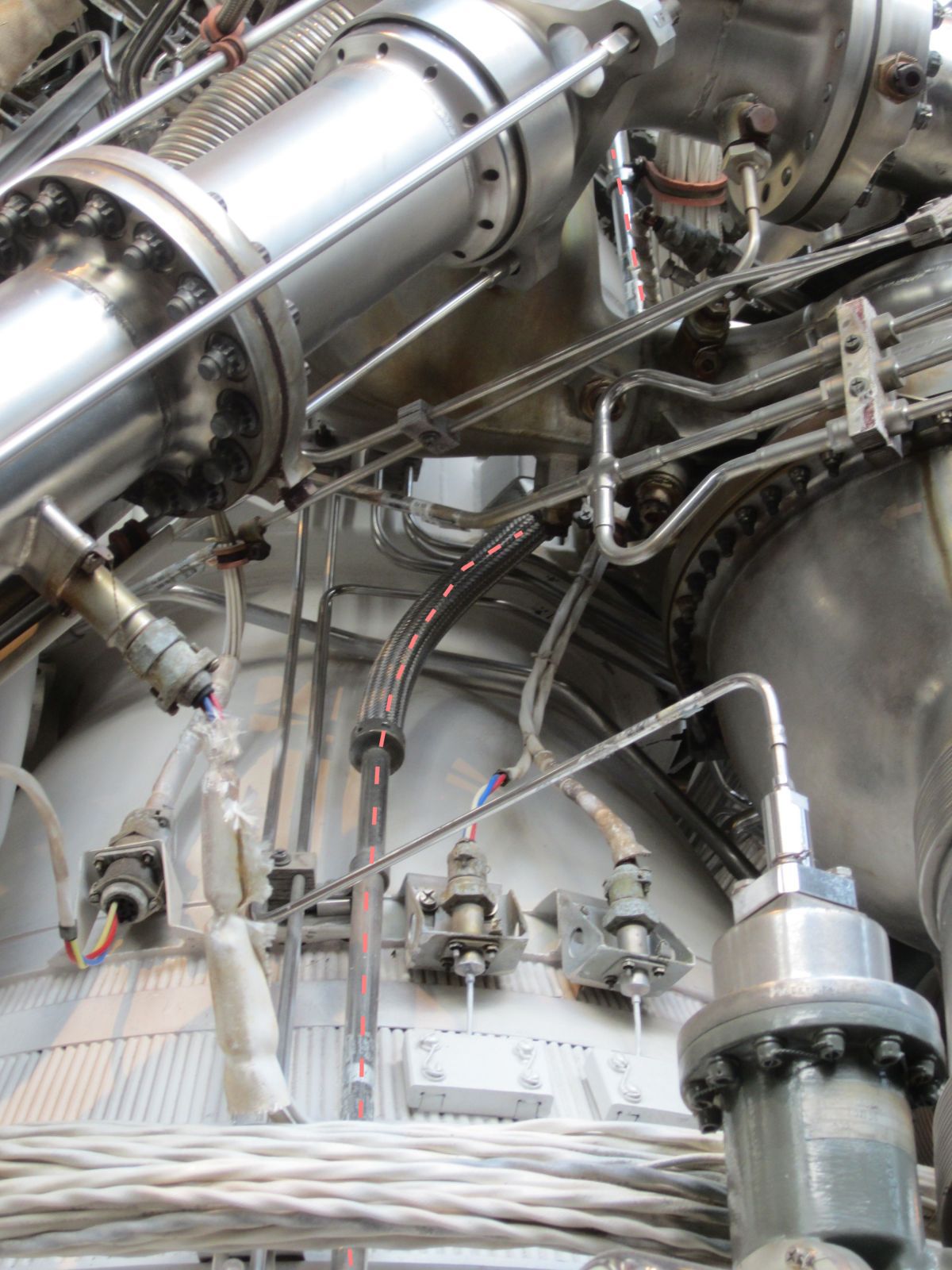
The ASI burned a small quantity of LH2 and LOX, producing a flame that ignited the propellants in the combustion chamber at engine start and continued to burn until engine cut-off. It was supplied by a LOX line and a LH2 fuel line. The stainless-steel ASI fuel line was attached to the fuel inlet manifold and snaked it way to the engine top where it connected to the ASI. Stainless-steel braid-covered flexible bellows in three places along the line's length were intended accommodate thermal expansion and isolate the engine's vibration from the components to which it was attached. Engineers suspected that the ASI fuel line was vibrating in resonance with engine vibration, causing it to break at the bellows. The broken line would then leak LH2, chilling the engine exterior. As the break progressed and the leak became worse combustion gasses would begin to flow backwards through the ASI and out the broken fuel line, accounting for the subsequent temperature rise, as well as the reduction in chamber pressure and engine performance. Meanwhile, the ASI's LOX supply continued to flow and without LH2 to burn started to burn the metal comprising the ASI and the injector components, eventually leading to chunks of the injector breaking off and puncturing the thrust chamber wall of S-II engine No. 2. The chamber pressure degradation eventually reached the point that the sensor tripped and shut down the engine, probably just seconds before the failure became a catastrophic explosion and fire.
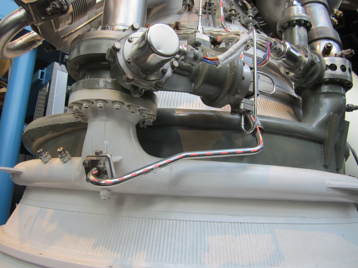
| The USSRC J-2 has the old-style ASI Fuel Line with flexible bellows instead of the later solid line. | ||
|---|---|---|
 |
 |
 |
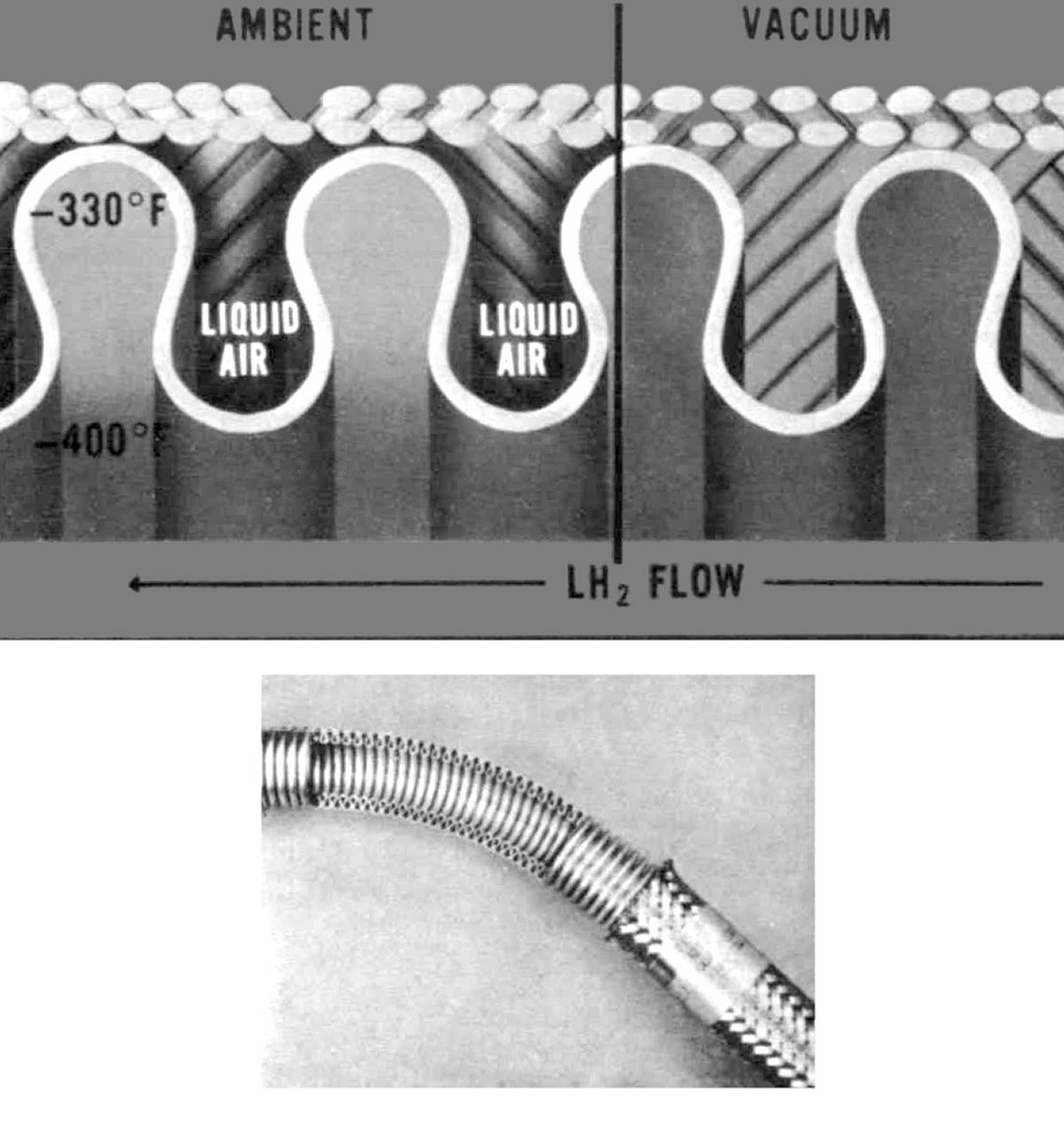
| ASI Fuel Line, Original (L) and Revised (R) | ASI Fuel Line Bellows (heriocrelics.org) |
ASI Fuel Line Origin in Fuel Manifold |
 |
 |
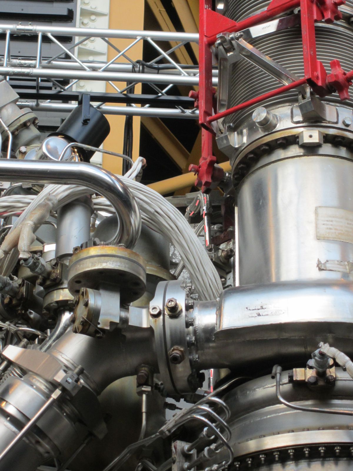 |
| ASI Fuel Line First Bellows | ASI Fuel Line Second Bellows | ASI Fuel Line Third Bellows |
The engineers now had an explanation for the telemetry data but couldn't understand why this phenomenon had not occurred during any of the 289 J-2 ground tests or the early flight tests. Then Rocketdyne engineer Marshall McClure wondered what it was about the space environment that made the engine behave differently. A special vacuum tank was built in just two weeks and eight ASI fuel lines were subjected to flight loads and vibration; all eight lines ruptured. As it turned out when the ASI fuel line flexible bellows were exposed to air the super-cold LH2 liquefied the air, which formed a viscous vibration damping medium around the bellows and inside the stainless steel braid. The liquid air that prevented resonant vibration from developing in air was absent in space! This explained why the ground and Saturn IB tests (where the S-IVB was the second stage and the liquid air didn't fully gasify) had been successful. It still did not explain the successful Saturn SA-501 (Apollo 4) tests, but perhaps in that case the absence of pogo vibration had not weakened the lines.
Rocketdyne modified the ASI fuel lines, replacing the flexible braided bellows with S-turns that served the same purpose, and attaching the line more securely to the J-2's exterior. Rocketdyne tested this new configuration in the J-4 liquid propellant rocket engine high-altitude test cell at the Arnold Engineering Development Center, an Air Force facility near Tullahoma, Tennessee. The new ASI fuel line performed flawlessly, and just in time for the first crewed Saturn V mission, AS-503 (Apollo 8). The five J-2s performed flawlessly.
The SA-502 J-2 difficulties clearly illustrate how the smallest oversight can result in excitement of the highest order, one of the things that makes rocket development most rewarding.
References
Bilstein, Roger E. Stages to Saturn NASA SP-4206 (Washington, DC: NASA History Office, 1996).
Dawson, Virginia P. and Mark D. Bowles Taming Liquid Hydrogen: The Centaur Upper Stage Rocket 1958 – 2002 NASA SP-2004-4230 (Washington, D.C.: NASA, 2004).
Dougherty, Jr., N.S. and C.A. Rafferty Altitude Developmental Testing of the J-2 Rocket Engine in Propulsion Engine Test Cell (J-4) (Tests J4-1801-39 through J4-1801-41) AEDC-TR-68-266 (Arnold Air Force Station, TN: Feb 1969).
Hunley, J.D. Technology for U.S. Space-Launch Vehicles, 1926 – 1991 (College Station, TX: Texas A&M University Press, 2007).
J-2 Engine AS-502 (Apollo 6) Flight Report, S-II and S-IVB Stages, Volume 2: S-II Stage Failure Analysis R-7450-2 (Conoga Park, CA: Rocketdyne Division, 17 Jun 1968).
J-2 Engine AS-502 (Apollo 6) Flight Report, S-II and S-IVB Stages, Volume 3: S-IVB Stage Failure Analysis R-7450-2 (Conoga Park, CA: Rocketdyne Division, 17 Jun 1968).
Kraemer, Robert S. Rocketdyne: Powering Humans into Space (Reston, VA: AIAA, 2006).
Mulready, Dick. Advanced Engine Develoment at Pratt & Whitney: The Inside Story of Eight Special Projects 1946 – 1971 (Warrendale, PA: Society of Automotive Engineers, 2001).
Muse, W.W. and D.E. Franklin Altitude Testing of the J-2 Rocket Engine in Propulsion Engine Test Cell (J-4) (Tests J4-1554-01 through J$-1554-11) AEDC-TR-67-86 (Arnold Air Force Station, TN: Jul 1967).
| Engine | Model 39 | Rocketdyne 75-110-A-7 | Rocketdyne LR89-5 | Rocketdyne LR105-5 | Aerojet LR87-AJ-7 | Aerojet LR91-AJ-7 | Rocketdyne H-1D | Rocketdyne F-1 | Pratt & Whitney RL10 | Rocketdyne J-2 |
|---|---|---|---|---|---|---|---|---|---|---|
| Used In | German V-2 | Redstone | Atlas E, F Booster | Atlas E, F Sustainer | Titan GLV Stage 1 | Titan GLV Stage 2 | Saturn I, IB | Saturn S-IC | Centaur Saturn I Stage 2 | Saturn S-II, S-IVB |
| Era | 1943 | 1953 | 1960 | 1960 | 1962 | 1962 | 1961 | 1964 | 1959 | 1966 |
| Thrust, SL (lb) | 55,000 | 82,977 | 163,211 | 60,473 | 212,827 | 50,627 | 204,300 | 1,522,000 | ||
| Thrust, Vac (lb) | ? | 93,565 | 184,905 | 86,866 | 244,165 | 100,000 | 213,051 | 1,748,200 | 15,000 | 230,000 |
| Burn Time (sec) | 60 | 155 | 135 | 430 | 139 | 180 | 150 | 165 | 470 | 500 |
| Chamber Pressure (psi) | 218 – 239 | 318 | 580 | 696 | 784 | 804 | 701 | 1,125 | 475 | 787 |
| Specific Impulse (sec) | 203 – 239 | 235 – 265 | 248 – 282 | 220 –316 | 258 – 296 | 160 – 316 | 255 – 289 | 265.4 – 304.1 | 444 | – 425 |
| Propellant Flow (gps) | 33.5 | 41.3 | 47.7 | 20 | 81.3 | 26.9 | 93.5 | 674 | 12.5 | 19.1 |
| Propellant Flow (lb/sec) | 286 | 355 | 458 | 193.2 | 824 | 322 | 760 | 5,785 | 34 | 544 |
| Nozzle Expansion Ratio | 2.83 | 3.61 | 8 | 25 | 8 | 45 | 8 | 16 | 57 | 27.5 |
| Engine Weight (lb) | 2,484 | 1,479 | 1,580 | 1,010 | 1,571 | 1,245 | 1,399 | 18,500 | 298 | 3,480 |
| Thrust / Weight, SL | 22 | 56 | 103 | 60 | 136 | 80 | 146 | 81 | 50 | 66.1 |
| Fuel | 75% Ethanol | 75% Ethanol | RP-1 | RP-1 | A-50 | A-50 | RP-1 | RP-1 | LH2 | LH2 |
| Oxidizer | LOX | LOX | LOX | LOX | N2O4 | N2O4 | LOX | LOX | LOX | LOX |
| Mixture Ratio (Ox/Fuel) | 1.13 | 1.324 | 2.21 | 2.25 | 1.9 | 1.79 | 2.34 | 2.27 | 5.0 | 4.5 – 5.5 |
| Turbopump Output (hp) | 580 | 758 | 3,140 | 1,663 | 5,180 | 2,122 | 4,021 | 55,000 | 687 | 2,358 (LOX) 7,977 (LH2) |
| Turbine RPM | 3,800 | 4,718 | 30,986 | 30,000 | 25,172 | 23,685 | 6,680 | 5,488 | 32,500 | 8,753 (LOX) 28,130 (LH2) |
--- On To Part 8.30 - The Saturn S-IVB Stage ---
Send mail to
![]() with questions or comments about this web site.
with questions or comments about this web site.
![]()