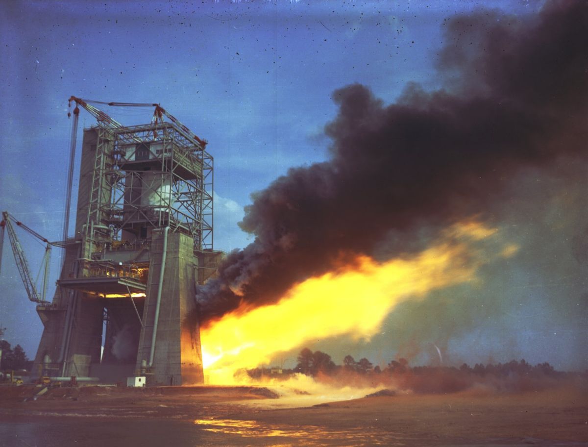
S-IC_T Under Test at MSFC (NASA)
U.S. Manned Rocket Propulsion Evolution
Part 8.10: The Saturn V S-IC Stage
Compiled by Kimble D. McCutcheon
Published 1 May 2021; Revised 24 Sep 2023
S-IC_T Under Test at MSFC (NASA) |
The S-IC had the unenviable task of getting the huge Saturn V rocket off the ground, lofting it to an altitude of about 40 miles and accelerating it to a velocity of about 6,000 mph. When the Saturn V left the ground, it weighed about 6.2M lbs; after just 150 seconds when the the S-IC completed its launch role and was jettisoned, what remained of the rocket weighed only 1.32M lb. The S-1C, which weighed 303,000 lb empty, had consumed 4,578,000 lb of propellant in just 150 seconds; nearly 5/6 of the Saturn V’s weight was in its first stage. |
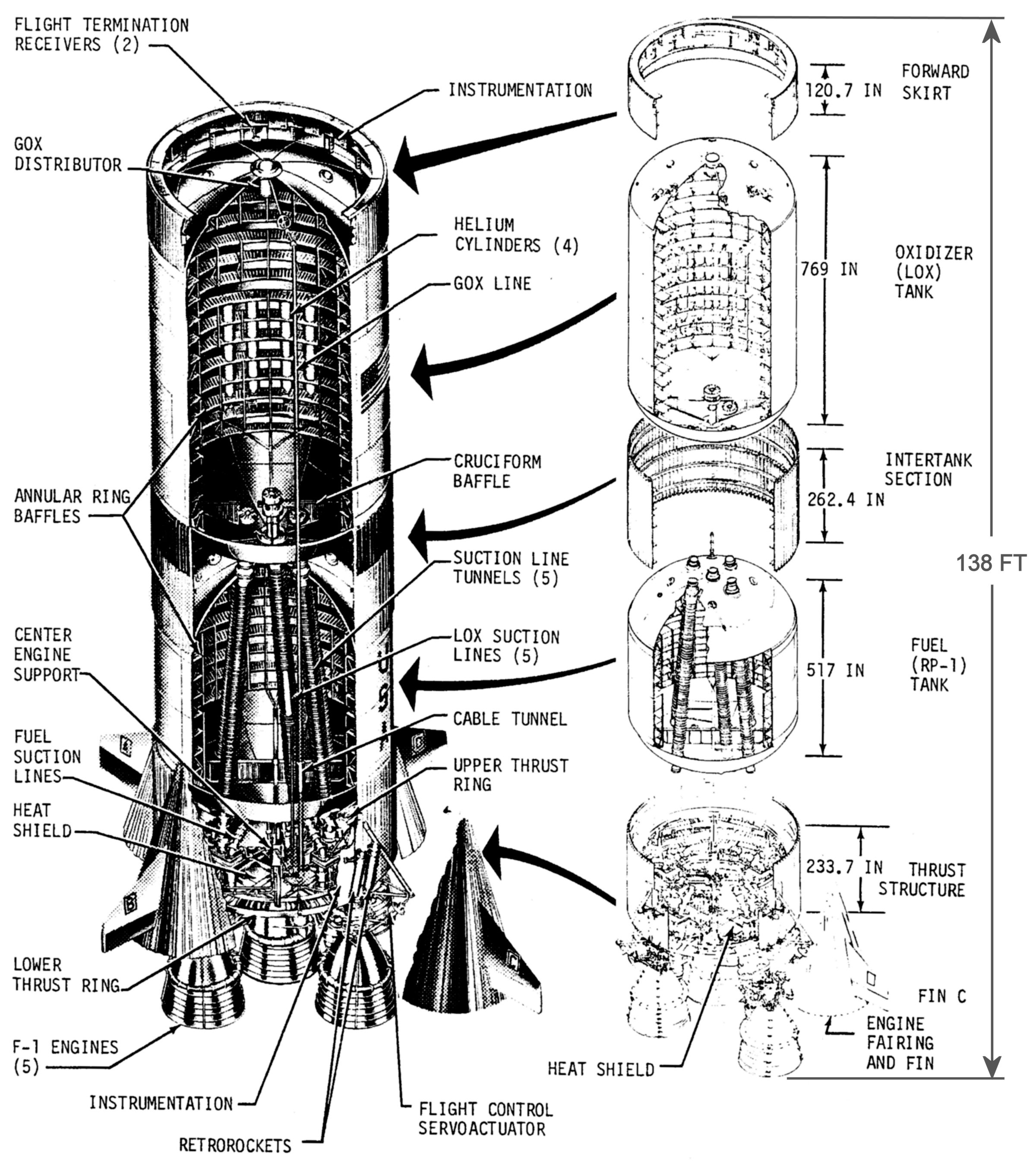 |
| S-IC Internals |
S-IC Overview
The S-IC was 33 ft in diameter and 138 ft high; two large propellant tanks comprised most of its volume. The fuel tank contained 209,000 gal (1,400,000 lb) of RP-1. Above the fuel tank, the LOX tank’s volume was 334,500 gal (3,178,000 lb).
At the S-IC’s base were five F-1 rocket engines that burned a combination of RP-1 and LOX. The four outer F-1s were gimbaled, allowing the Saturn V guidance and control system to control roll, pitch and yaw during the S-1C’s burn; the center engine was fixed.
The engines were attached to a 24-ton, mostly aluminum alloy, thrust structure, 33 ft in diameter and about 20 ft tall, which uniformly distributed thrust forces from the five engines to the fuel tank periphery. The thrust structure was composed of a lower thrust ring assembly, center engine support, four holddown posts, four engine thrust posts, propellant distribution plumbing and an upper thrust ring assembly. Corrugated 7075-T6 aluminum alloy skin panels stiffened with intermediate aluminum alloy rings covered the thrust structure’s internal components. A heat shield at the thrust structure’s base protected internal components from engine heat. The heat shield was constructed of 1.0” thick 16-7 PH stainless steel honeycomb brazed to 0.010” steel face sheets.
The 44-ft tall aluminum alloy fuel tank consisted of a short cylindrical barrel section closed at each end by ellipsoidal bulkheads. The barrel section 2219-T87 aluminum alloy skin ranged in thickness from 0.193” at its base to 0.170” at its top in 4 steps. The skin panels were stiffened with integrally-machined T-section stiffeners along with ring baffles to further stiffen the skin and inhibit fuel sloshing. At the cylinder-ellipsoid circumferential interface were extruded aluminum alloy Y-rings to which the cylinder and ellipsoids were welded; the Y-rings also provided a structural interface between the tank and the thrust structure and intertank structure (more about which later). At its base, 10 fuel suction lines fed the engines in groups of 2. Within the tank were five insulated LOX tunnels that housed LOX suction lines connecting the LOX tank to the engines.
The 64-ft tall LOX tank was constructed similarly to the fuel tank. Its skin was also of 2219-Y87 aluminum allow varying in thickness from 0.254” to 0.190” in 8 steps. Its five LOX outlets connected to 17” suction lines that ran inside the fuel tank LOX tunnels. At the suction line aft ends, within the thrust structure, were normally-open pneumatically-controlled prevalves that were emergency backups to the engine’s main LOX valves, followed by flexible bellows to accommodate vibration and temperature-related expansion and contraction. Within the LOX tank, attached to its ring baffles, were four 31 ft³ high-pressure helium bottles, the contents of which provided pressurization for the propellant tanks. At the tank bottom is a cruciform baffle assembly that helped prevent LOX swirling as the tank emptied.
Connecting the fuel and LOX tanks was an intertank structure composed of corrugated 7075-T6 aluminum alloy skin panels and five ring frames. The intertank was attached to the fuel and LOX tank Y-rings via 216 fasteners each. The intertank also provided LOX fill and drain provisions.
Above the LOX tank is a forward skirt that interfaces with Saturn V Stage 2. Like the intertank, it is constructed of corrugated 7075-T6 aluminum alloy skin panels stiffened by ring frames and stringers. The forward skirt also contains various electronic and electrical components used for monitoring, telemetry, staging and flight termination, as well as LOX tank venting apparatus.
Each outboard F-1 engine was protected from aerodynamic loads by conical fairings to which aerodynamic stabilization fins were attached. The fairing bottoms and fins were constructed of titanium; the fairing tops of aluminum alloy.
Designed by MSFC and Boeing engineers, the first three test articles and first two flight vehicles were built at MSFC using tooling produced by Boeing’s Wichita, Kansas facility. Once these were complete the tooling was moved to the Michoud Assembly Facility near New Orleans, Louisiana, where production S-ICs were manufactured. Completed S-IC stages were shipped by barge to the Mississippi Test Facility (now Stennis Space Center) where they were tested, and ultimately shipped by barge to the Kennedy Space Center, where they became part of the complete Saturn V stack.
S-IC Systems
Fuel
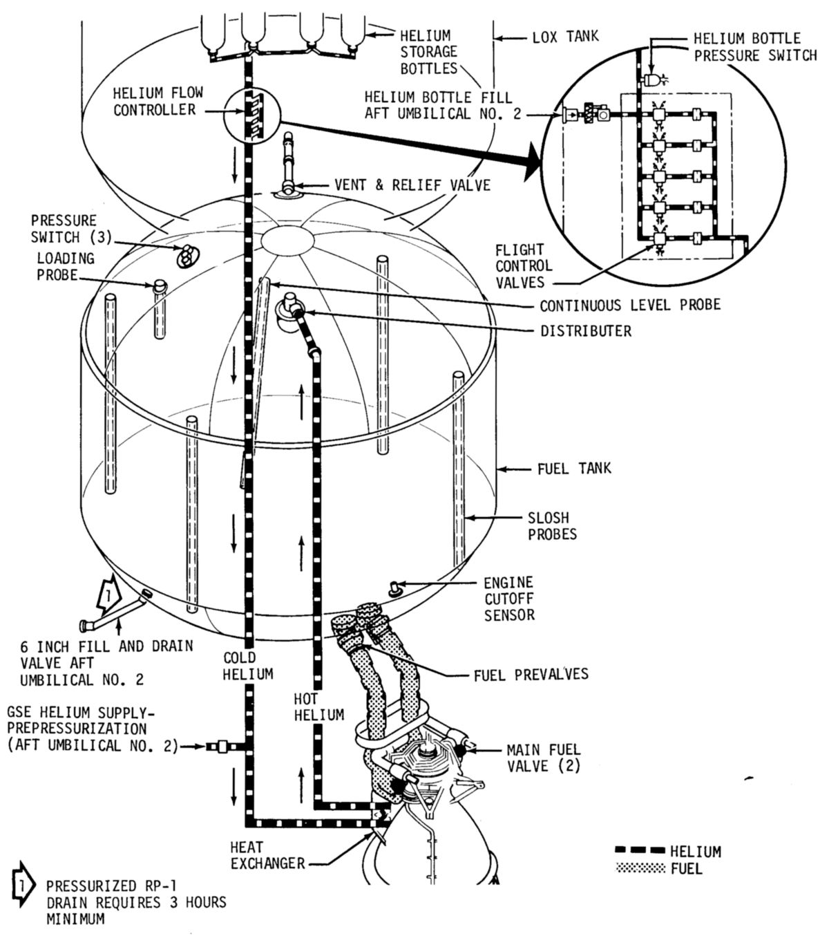
The fuel tank was filled via a 6" duct connecting an external intertank umbilical opening to the tank bottom through a ball fill-and-drain valve. Fuel flowed at 200 gpm until the tank was 10% full, 2,000 gpm thereafter. A fuel loading probe and nine temperature sensors facilitated fuel tank filling by signaling a full fuel load and allowing real-time density computation. Fuel could also be drained, if necessary, via the same fill-drain system. Two fuel feed lines connected the fuel tank to each engine via normally-open pneumatically-operated prevalves that were emergency backups to the engine’s main fuel valves. A fuel conditioning system bubbled gaseous nitrogen through the fuel feed lines to prevent temperature stratification prior to launch. A cutoff sensor mounted near the tank bottom signaled fuel exhaustion and initiated engine shutdown; this backed up to a similar LOX depletion detection scheme that normally controlled engine shutdown. Fuel level sensors, in conjunction with the S-IC telemetry system, allowed ground support to monitor fuel levels. The fuel tank was pressurized by gaseous helium that originated from high-pressure bottles within the LOX tank. These helium tanks were initially filled to 1,660 psig, but once LOX was loaded and the bottles were cold, helium pressure was raised to about 3,100 psig. Cold helium was heated by engine heat exchangers before entering the fuel tank via a pressure regulator. Tank pressurization ensured sufficient head pressure for engine start and operation.
LOX
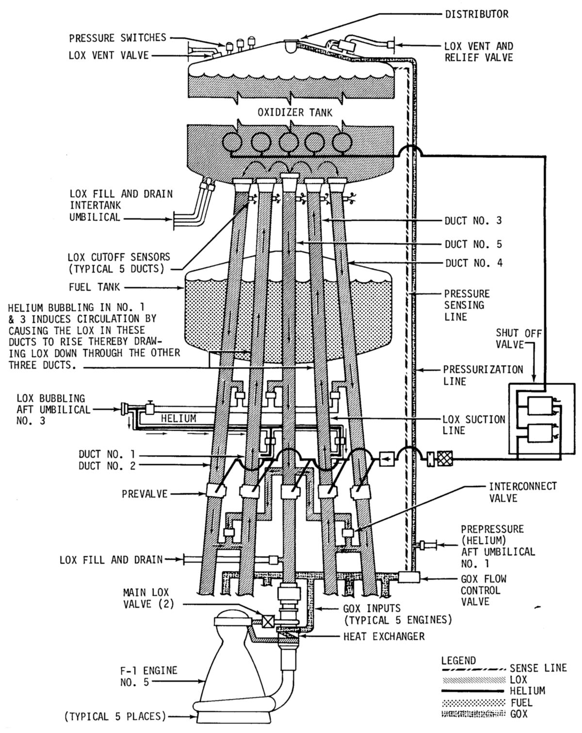
The LOX tank was filled under pressure via two 6” LOX fill-and-drain lines and valves; initial fill rate was 1,500 gpm to reduce LOX splashing until the tank was 6.5% full, then 10,000 gpm until the tank was 95% full, and 1,500 gpm for final filling. Four LOX liquid-level probes continuously monitored tank LOX levels. The LOX tank could be drained through the fill-and-drain path. The LOX, whose temperature was -297°F at sea level pressure, continuously boiled away; additional LOX was periodically added by GSE to make up for the loss. Although the LOX boiling phenomenon occurred anywhere it contacted the tank inner surface, it was most troublesome within the five LOX suction lines, which, although 17” in diameter, were too slim to maintain self-contained convective currents. To prevent LOX geysering and bubble formation that could cause LOX pump cavitation, gaseous helium was bubbled from the suction line bases of all five suction lines. This helium, supplied by GSE, was lost along with the GOX that was boiling away. This same helium was also used to provide 26 psia tank pressure prior to engine start. Once the engines were running, some of the LOX was evaporated in the engine heat exchanges and the heated GOX used for LOX tank pressurization at 18 – 23 psia. Dry nitrogen was used to slightly pressurize the LOX tank during S-IC storage to prevent moisture from entering its tanks. Cutoff sensors near the top of each LOX suction line assured safe engine shutdown while leaving a minimum amount of unused LOX.
Pogo Suppression
The term “pogo” was coined to describe a low-frequency (3 – 5 Hz) longitudinal vibration resulting from sympathetic coupling of vehicle structure, propellant delivery and engine thrust resonant frequencies. In the S-IC’s case, flexibility in the center engine support structure allowed the center engine’s LOX suction line’s length to vary, which caused LOX pressure at the LOX pump entrance to vary, which caused engine thrust to vary… This phenomenon was conveyed to the outer engines and pretty soon the entire rocket was shaking at more than the ±0.2g limit. On the unmanned Apollo 6 mission, this was strong enough to cause vehicle damage and may have been injurious to astronauts had they been aboard. Although the pogo problem was never completely solved, engineers continuously improved the situation.
One thing engineers did to help address the pogo issue was to pressurize cavities in the outboard LOX prevalves, causing them to serve as vibration absorbers. At T-11 minutes into the countdown GSE helium was used to pressurize the prevalve cavities while support personnel carefully monitored pressure and LOX liquid levels. This resulted in an accumulator of sorts that altered the LOX suction line’s resonant frequencies.
 |
 |
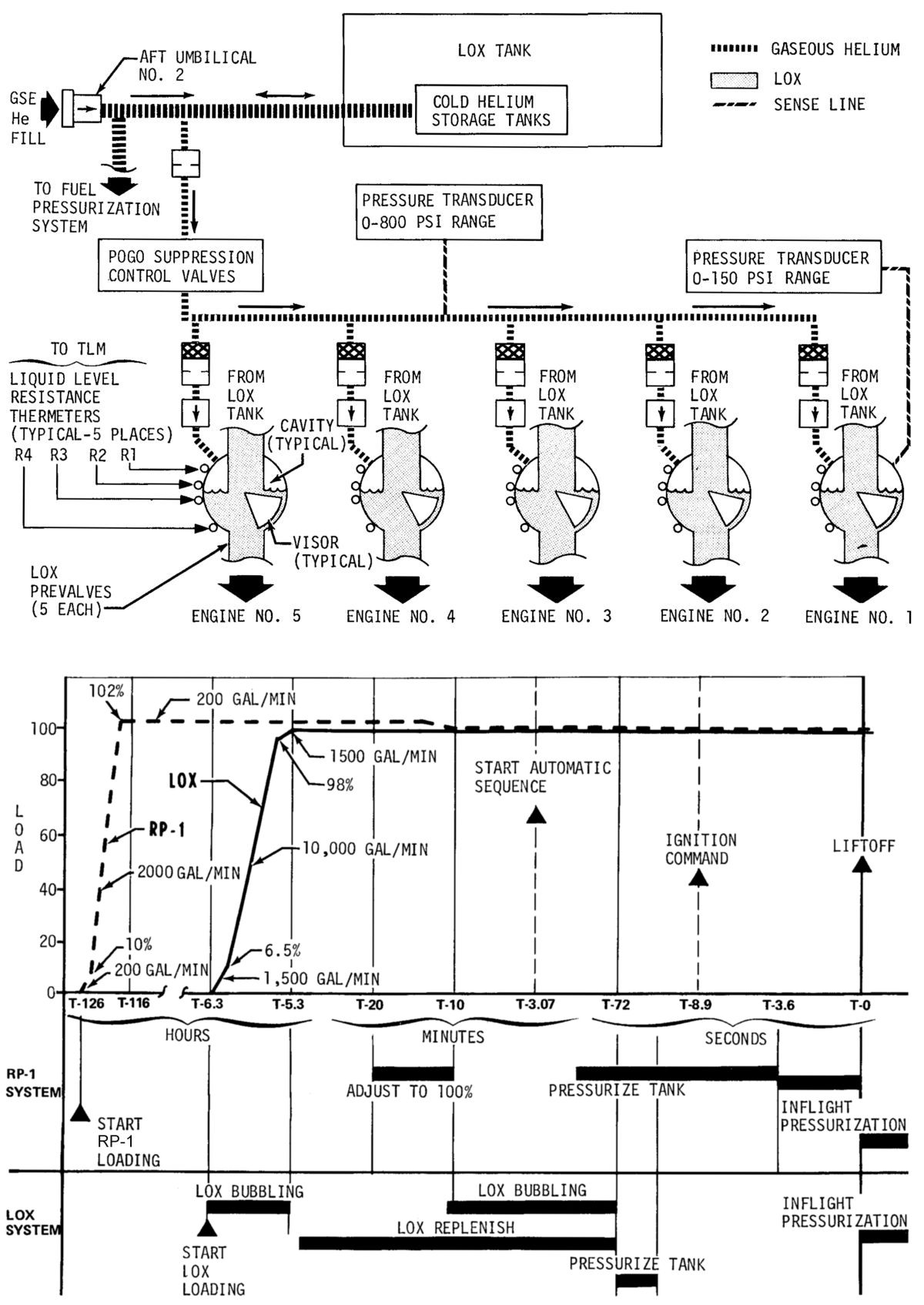 |
| Fuel System | LOX System | Top: Pogo Suppression Scheme; Bottom: Propellant Fill Schedule |
Fluid Power
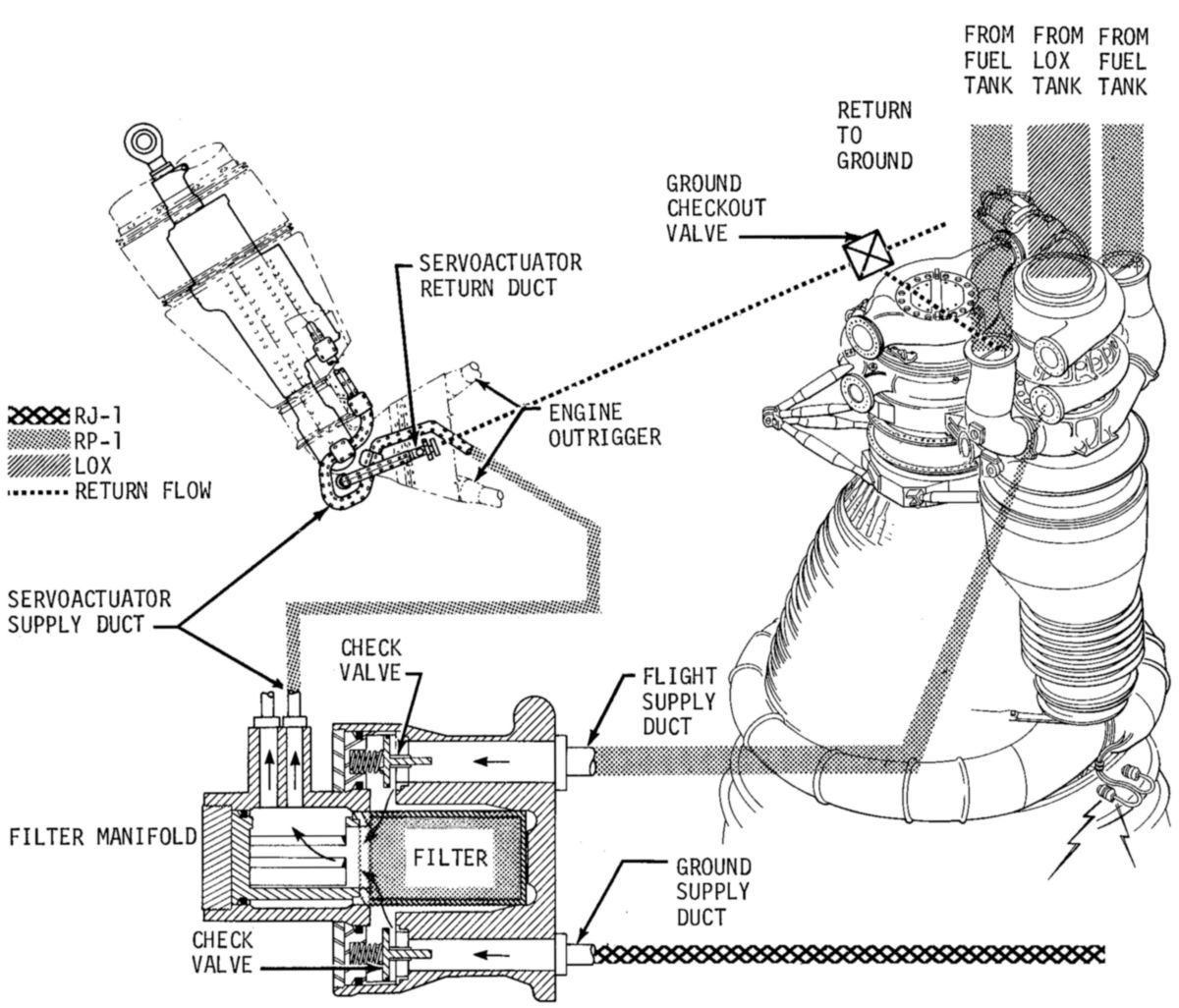
The S-IC stage used a clever fluid power arrangement for valve actuation and thrust vector control. High-pressure RP-1 tapped off the fuel pump outlet replaced rotary pumps and traditional hydraulic fluid for this application. However, during checkout and before engine start, GSE had to provide hydraulic pressure and RP-1 was hazardous due to its flammability. Instead of RP-1, GSE fluid power used RJ-1, a ramjet fuel, whose physical properties were very similar to RP-1 but whose flash point was high enough to avoid it being classified as flammable. Once the engines were running, GSE-supplied hydraulic pressure was replaced by engine fuel pressure. There were five fluid power systems, one for each engine. The fixed center engine directs its fluid pressure to close gas generator valves, main fuel valves and main LOX valves; outboard fluid pressure serves the thrust vectoring servoactuators.
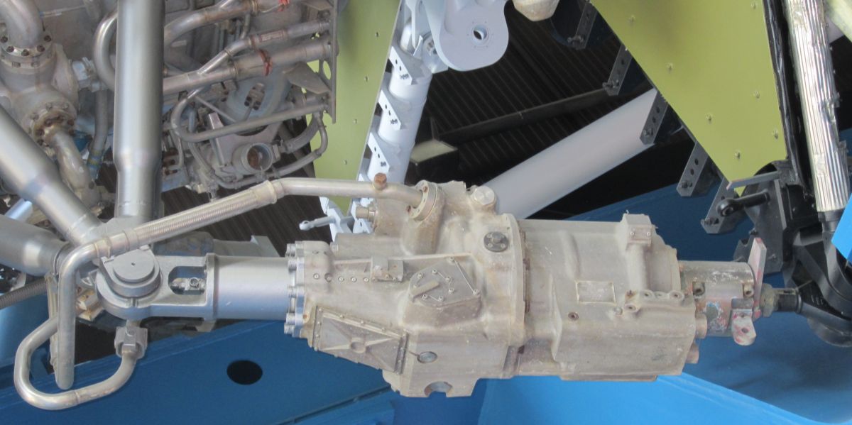
The servoactuators were things of beauty. Weighing 300 lb and 5 ft long, they had a stroke of 11" and could articulate the running F-1 engine through its full 5.25° of travel in just 1 second. MSFC engineers knew that quality servoactuators would be essential to mission success and released a very stringent request for proposals. Two companies, Hydraulic Research and Manufacturing Co., of Burbank, California and Moog, Inc. of East Aurora, New York, both submitted proposals that met the requirements equally. NASA decided to select both vendors and as a result some S-IC stages flew with Hydraulic Research servoactuators while others flew with ones from Moog.
 |
 |
 |
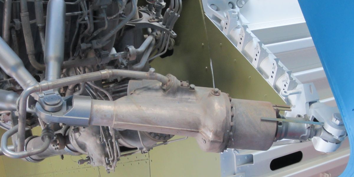 |
| Flight Control System | Servoactuator | Hydraulic Research Servoactuator | Moog Servoactuator |
Electrical
 |
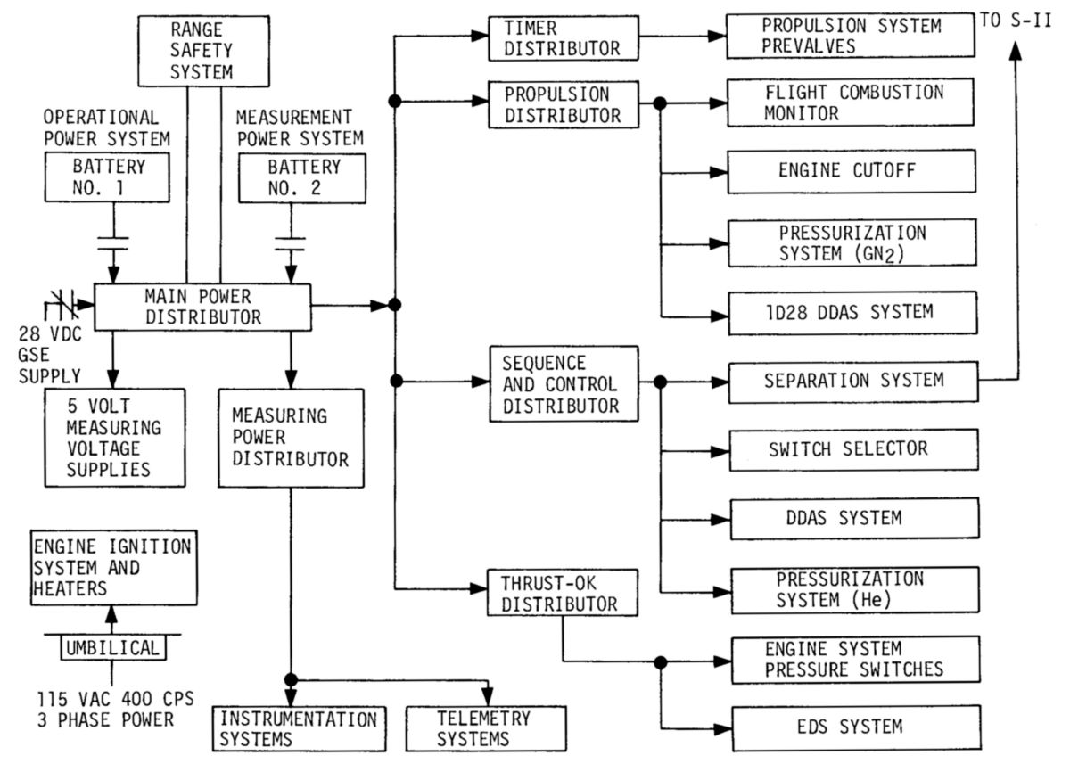 |
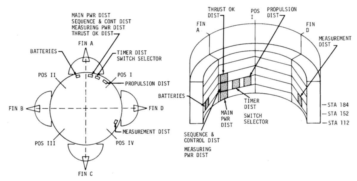
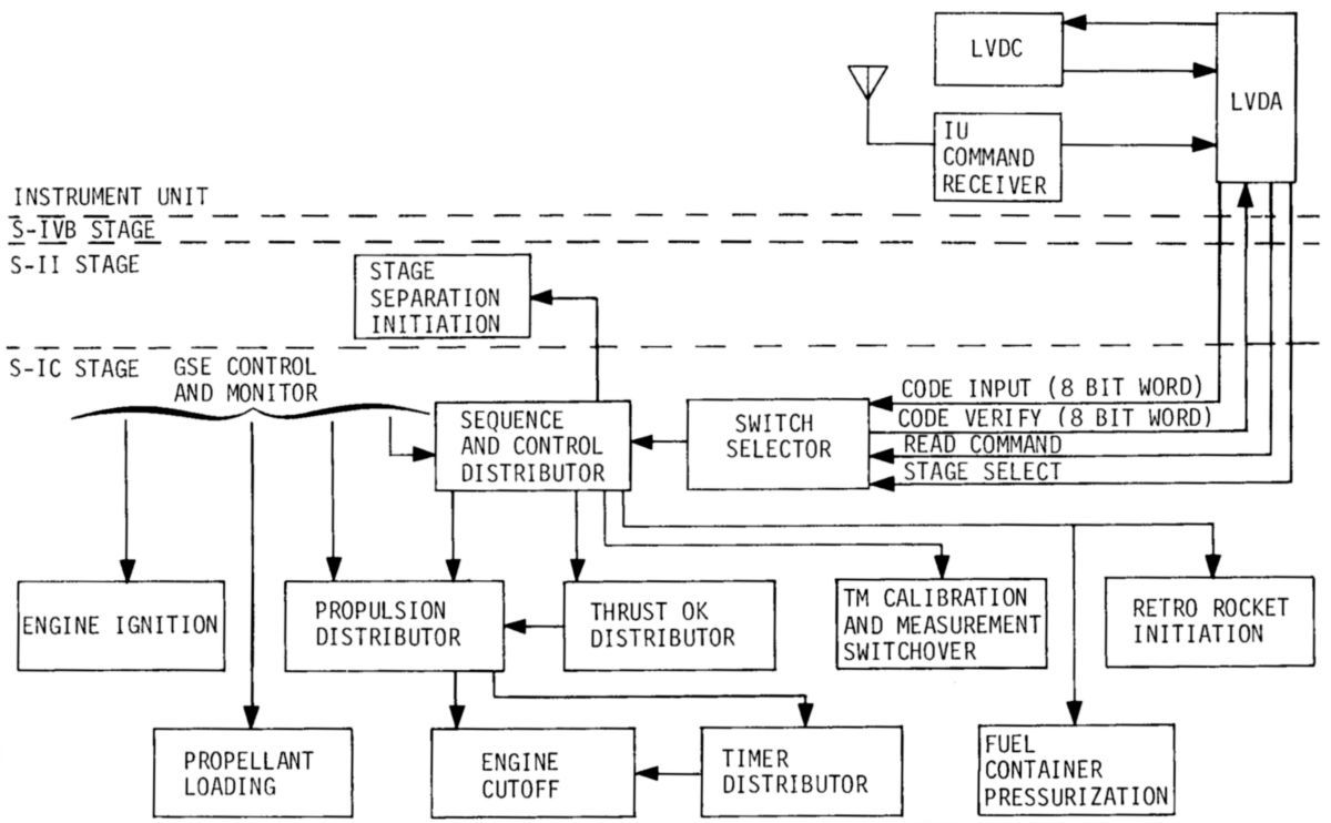 |
| Electrical Power Equipment Locations | Power Distribution | Sequence and Control |
Instrumentation
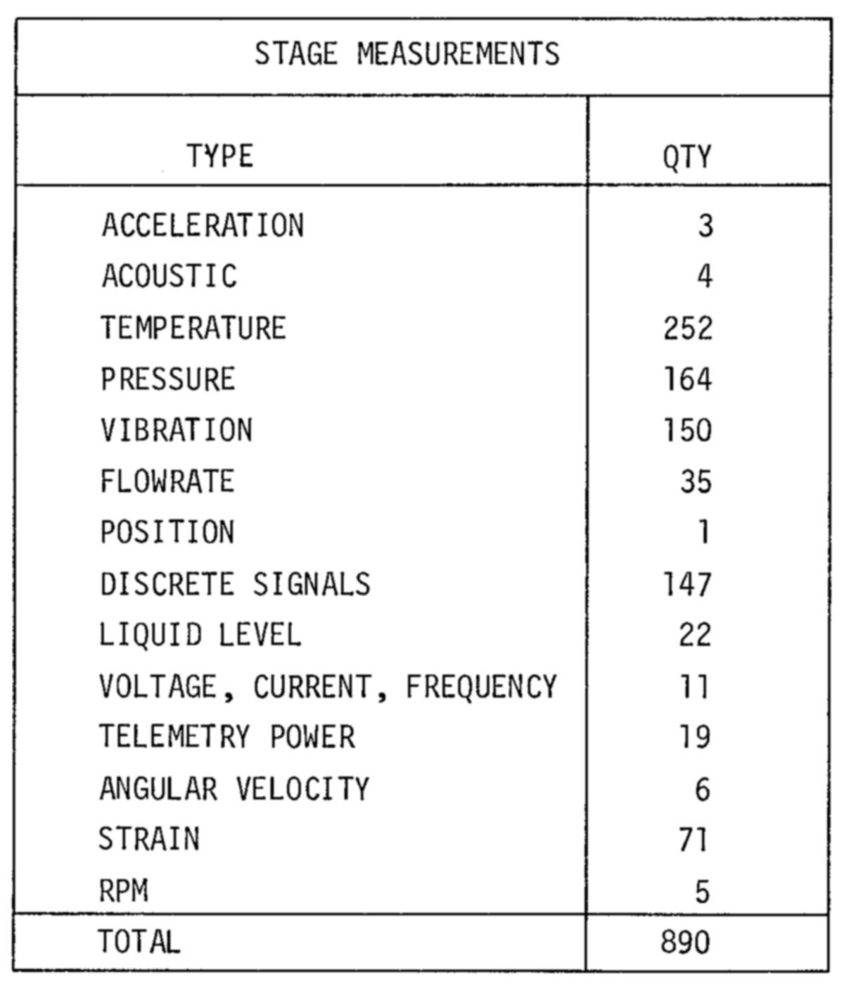
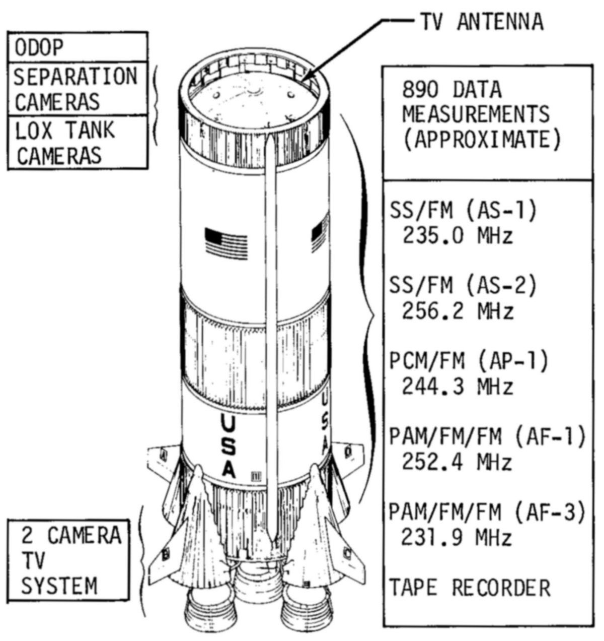
S-IC systems and components were monitored by the instrumentation system to produce about 900 data points, including valve positions, propellant levels, temperatures, voltages, currents, pressures, stress, vibration, acceleration, rpms, stage separation, etc. These data were then forwarded to GSE, flight telemetry and/or the instrument. This task involves sensors, transducers, signal conditioners, multiplexers, coding equipment and interconnects. Provisions existed to self-calibrate most of the instrumentation circuits.
Telemetry
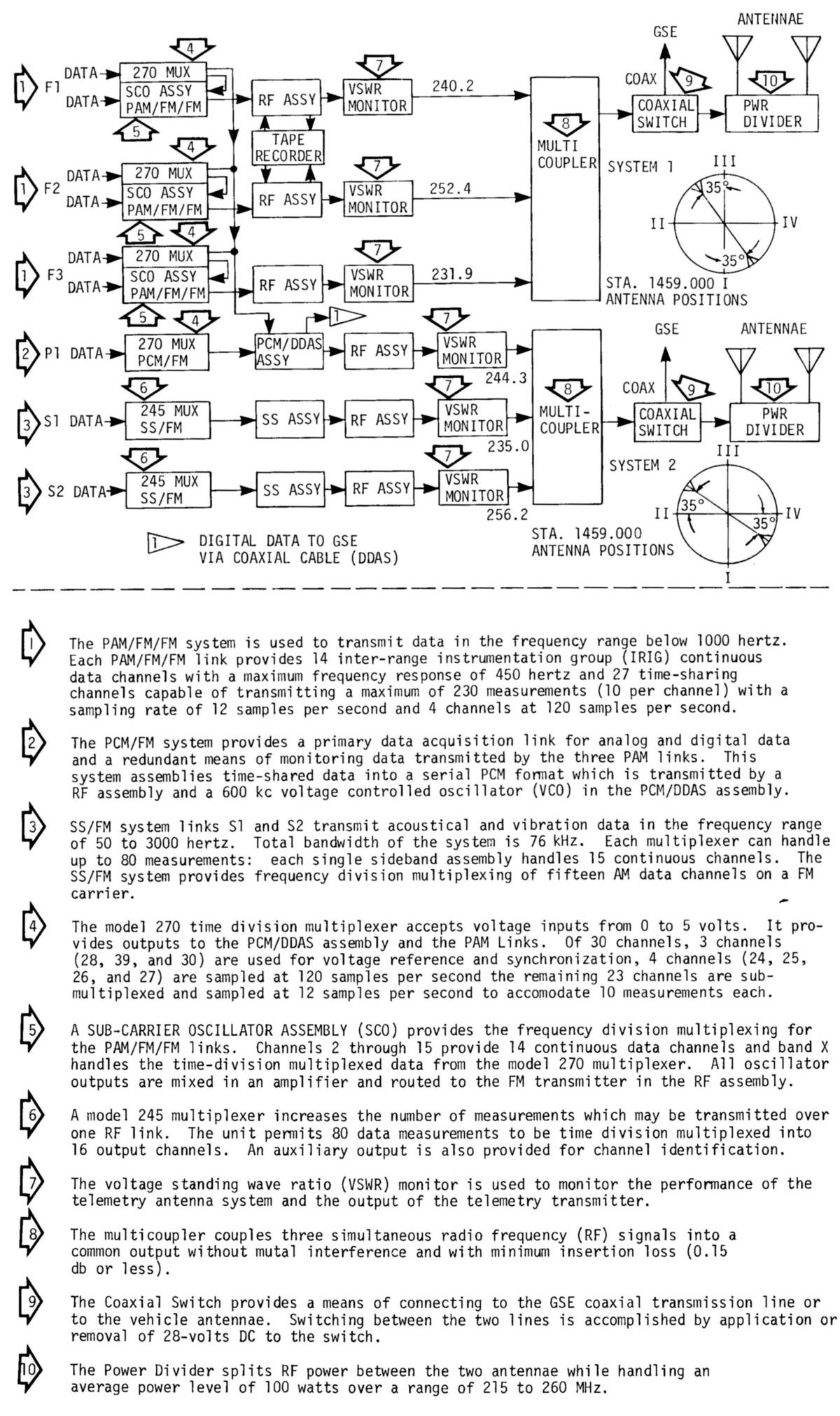
Telemetry is a method of flight information monitoring using radio links. Most S-IC telemetry components were housed in the thrust structure; radio-frequency components and a tape recorder were located in the forward skirt. Data were transmitted via two common antenna systems. Links F1, F2 and F3 were identical systems that transmitted narrow-band frequency-modulated data such as that generated by strain gages, temperature probes and pressure transducers. Each link could handle 14 continuously-transmitted data points and 234 time-shared measurements. Data was sampled either 12 or 120 times per second. Links S1 and S2 transmitted wide-band frequency-modulated vibration data. Each link could provide 15 continuous channels or up to 75 multiplexed channels. Link P1 transmitted either pulse-code-modulated (PCM) or digital data. Four analog and one digital data multiplexers supplied data to the P1 link. Since retro and ullage motor firing during stage separation could seriously degrade telemetry transmission, a tape recorder installed in the forward skirt held data values for delayed transmission.
Offset Doppler Tracking System (ODOP)
The ODOP was an elliptical tracking system that measured velocity toward or away from a tracking station. A continuous-wave UHF signal was transmitted from the ground, received by the S-IC, retransmitted and received simultaneously by three tracking stations. The Doppler shift was then analyzed to reveal vehicle position and velocity.
 |
 |
 |
| S-IC Stage Measurements | S-IC Instrumentation | S-IC Telemetry |
Separation
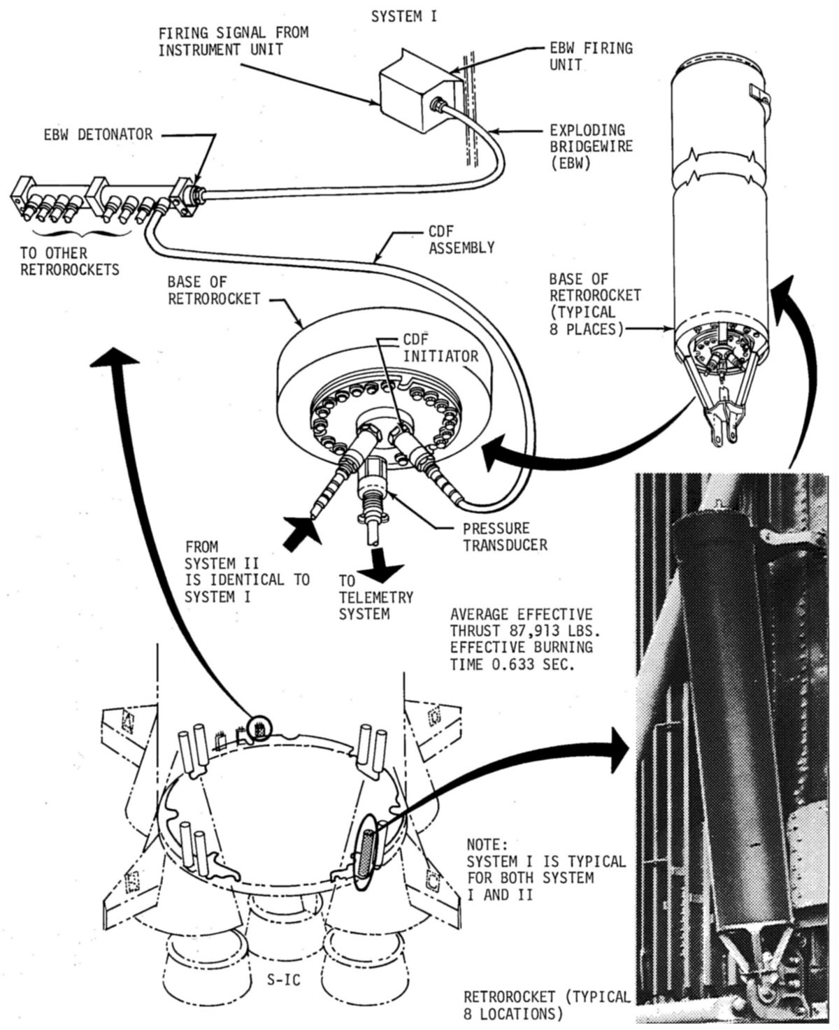
After LOX depletion, the instrument unit initiated separation of the first and second stages via the sequence and control distributor. The eight S-IC retro rockets were armed and then fired; a fraction of a second later the stage separation ordnance armed and fired, cutting electrical and mechanical connections between the stages.
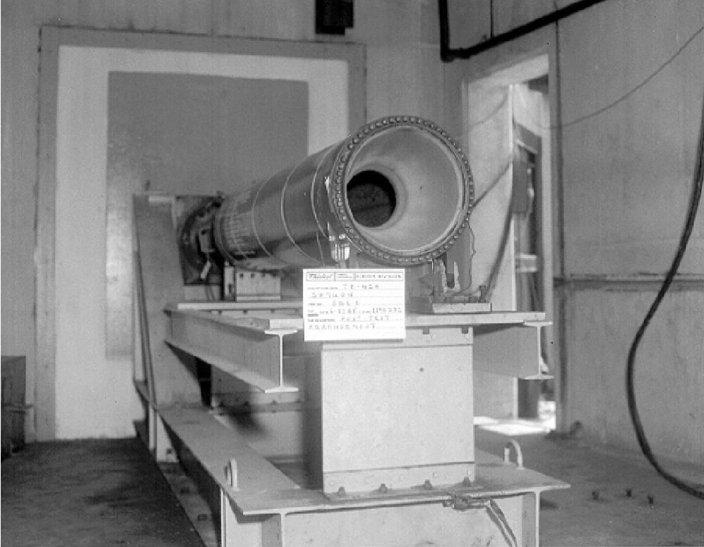
The forward-facing retro rocket motors were housed in the outboard F-1 aerodynamic fairings and fired through the aluminum fairing tops. The Thiokol TE-M-424-6 solid-propellant retro rocket motors each produced about 88,600 lbT for 0.667 sec and were fired just after staging in order to affect Stage 1 and Stage 2 separation before Stage 2 ignition. The retros had a diameter of 15.2", were 84.3" long and weighed 506 lb, which included a 208 lb propellant load consisting of 78% solids and 2% aluminum with the remaining 20% being a polysulfide binder. The propellant was cast with a 12-point star grain. While there were provisions for eight retro rockets, some flights omitted retro motors as a weight-saving measure.
 |
 |
| S-IC Stage Separation Scheme | S-IC Retro Rockets |
 |
 |
 |
 |
| Thiokol TE-M-424-6 Retro Rocket Motor | Thiokol TE-M-424-6 Details | Thiokol TE-M-424-6 Characteristics | Thiokol TE-M-424-6 Installation |
 |
| Control Pressure System |
 |
| Propellant Dispersion System |
Range Safety
The range safety system allowed ground controllers to terminate flight after a malfunction by shutting down the engines, blowing open the propellant tanks and dispersing the propellant. Two independent identical range safety systems were composed of electronic and ordnance components. The range safety officer would send a frequency-modulated radio signal that was received, conditioned, demodulated and decoded. Simultaneously, the engines were shut down and the stage ordnance armed. A second command from the ground ignited an explosive train where shaped charges blew open the propellant tanks.
Control Pressure
Pressurized gaseous nitrogen was used to actuate propellant system valves and purge F-1 engine subsystems. This involved both onboard and ground control pressure systems. A 2,200 in³ titanium alloy spherical storage bottle mounted within the thrust structure was pressurized in stages by GSE up to 3,250 psig just before launch. This high-pressure nitrogen was routed via manifolds, pressure regulator and tubing to the various control functions. The ground control pressure system was also capable of operating many onboard systems before launch thereby conserving the onboard nitrogen supply. Three high-pressure nitrogen storage bottles mounted within the thrust structure provided onboard purge to expel leaked propellant.
Environmental Control
Conditioned air, provided by GSE, was circulated through the thrust structure and forward skirt to control the temperature of electrical components and to prevent accumulation of a potentially flammable or explosive atmosphere. About six hrs prior to launch dry nitrogen replaced air as the circulating medium; this removes any moisture and continues until launch and umbilical disconnect.
 |
 |
| Hazardous Gas Detection, Forward Skirt | Hazardous Gas Detection, Thrust Structure |
Miscellaneous
Some S-ICs were fitted with still and movie cameras to record engine operation, tank interiors, staging, and other interesting flight events. These cameras were then jettisoned, returned to earth via parachute and recovered. Some S-ICs also included television cameras to monitor engine operation.
S-IC Operation
About 15 hrs before launch, ground support personnel filled the F-1 engine thrust chamber tubes with an inert ethylene glycol solution that served to smooth out the engine starting combustion sequence. The S-IC was loaded with RP-1 about 12 hrs before launch and LOX about 4 hrs before launch. When the designated launch time arrived, the center (No. 5) F-1 engine was started, followed by opposite pairs (1-3, 2-4) at 300 ms intervals. When full thrust was achieved on all five engines and if all systems were functioning properly, the launch umbilical tower’s nine swing arms disconnected umbilicals from the rocket and the four hold-down arms at the S-IC base were released, freeing the rocket to begin ascent. This ascent is initially controlled by a soft-release mechanism, which consists of 16 dies attached to the S-1C base and 16 greased tapered rods connected to the hold-down arm frames. The tapered rods were pulled through the dies as the rocket started its ascent, a process that lasted about half a second.
Once free of the soft-release mechanism, the rocket was free to rise vertically about 430 ft at which time it was clear of the launch umbilical tower. At that time it began its pre-programmed pitch and roll program that established the correct flight azimuth. At about T+69 seconds the vehicle experienced the point of maximum aerodynamic pressure. After about 135.5 seconds most of the propellant had been consumed and the center engine was shut down. The four outboard engines continued to burn until at least two LOX (or fuel) depletion indications was sensed, at which time the instrument unit shut down all remaining engines. About 600 ms later, the eight S-IC retro rockets were fired and the stage separation charges activated. The vehicle had then reached an altitude of about 205,000 ft. As the second stage fired and the remaining Saturn V components continued their journey, the S-IC stage’s momentum carried it to an altitude of about 366,000 ft, at which time it fell tail-first into the Atlantic ocean about 350 miles downrange from the Kennedy Space Center. Aerodynamic loading in conjunction with water impact destroyed the stage, which sank in the Atlantic.
 |
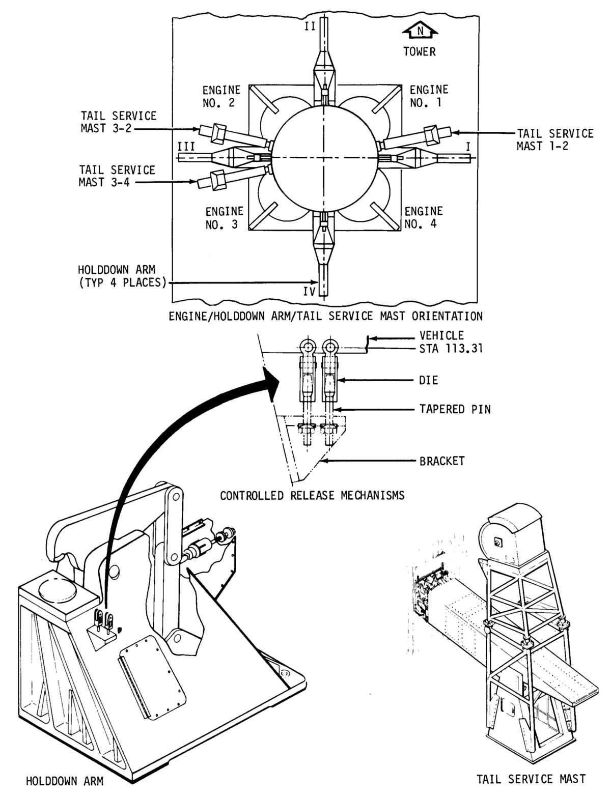 |
| Full-Duration S-1C Test at MSFC (Video) | Hold Down, Tail Service Mast, Controlled Release |
References
Saturn V News Reference (NASA, Boeing, Douglas, Rocketdyne, North American Rockwell, Dec 1968).
Saturn V Flight Manual, SA-503, MSFC-MAN-503 (MSFC, Alabama: MSFC, 1 Nov 1968).
Astrionics System Handbook: Saturn Launch Vehicles, MSFC no. IV-4-401-1 (MSFC, Alabama: MSFC, 1 Nov 1968).
--- On To Part 8.20 ---
Send mail to
![]() with questions or comments about this web site.
with questions or comments about this web site.
![]()