Apollo
Spacecraft
U.S. Manned Rocket Propulsion Evolution
Part 9.00: The Apollo Spacecraft
Compiled by Kimble D. McCutcheon
Published 20 Sep 2021; Revised 4 Aug 2022
Apollo Spacecraft |
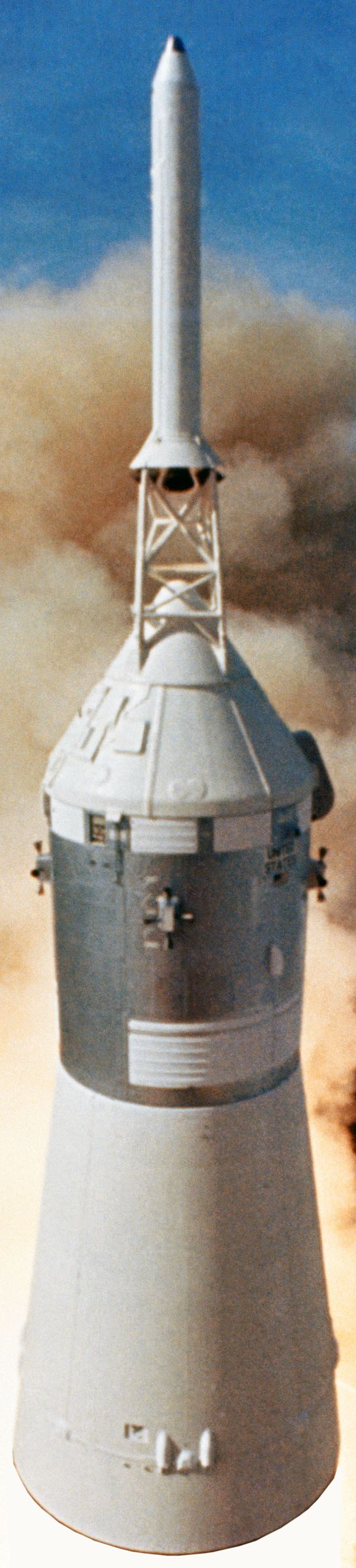
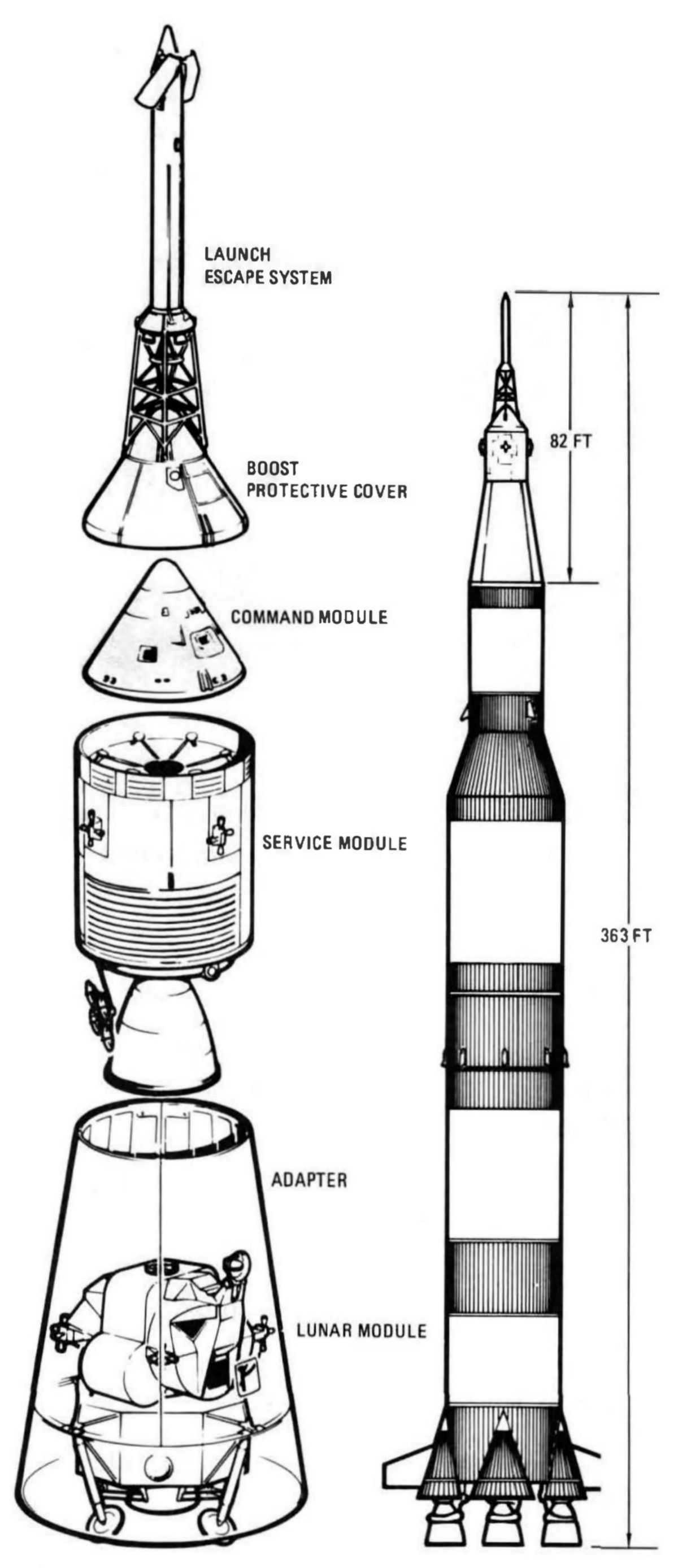
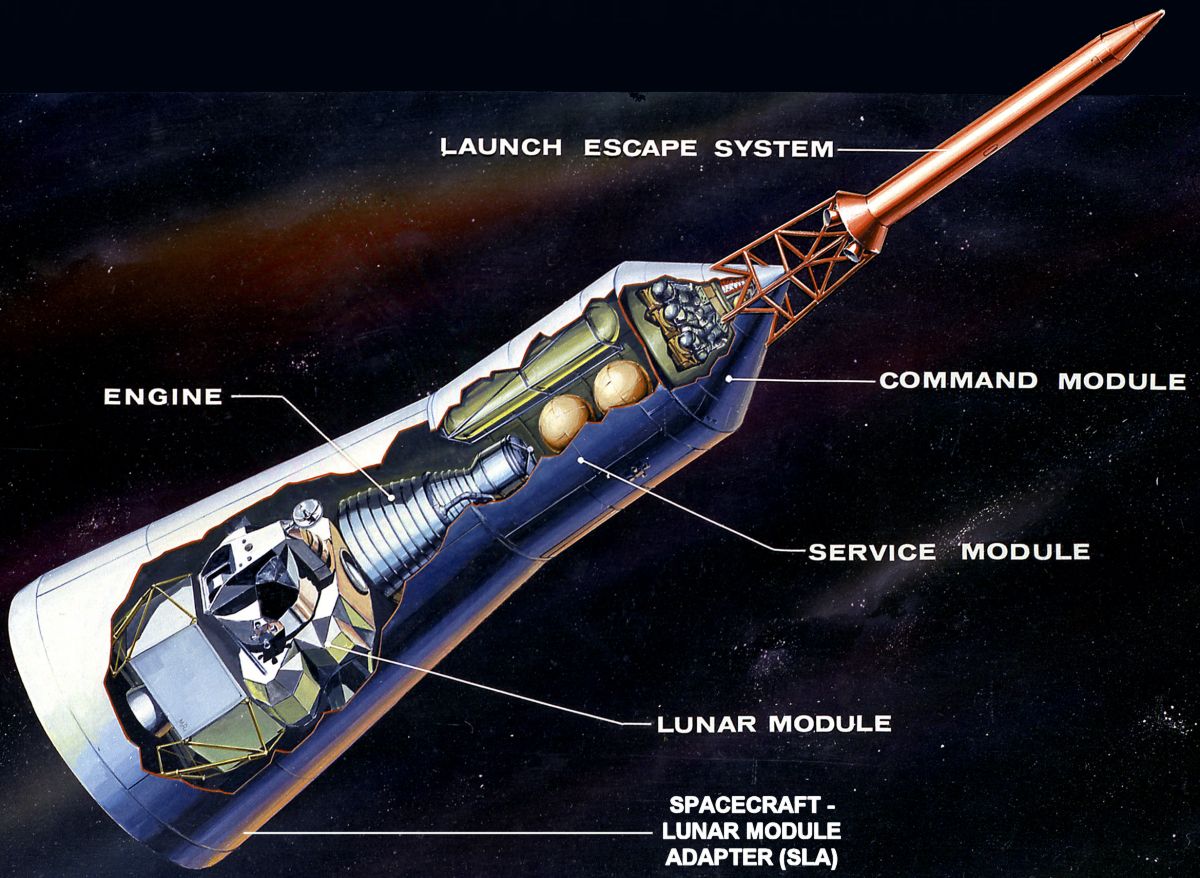
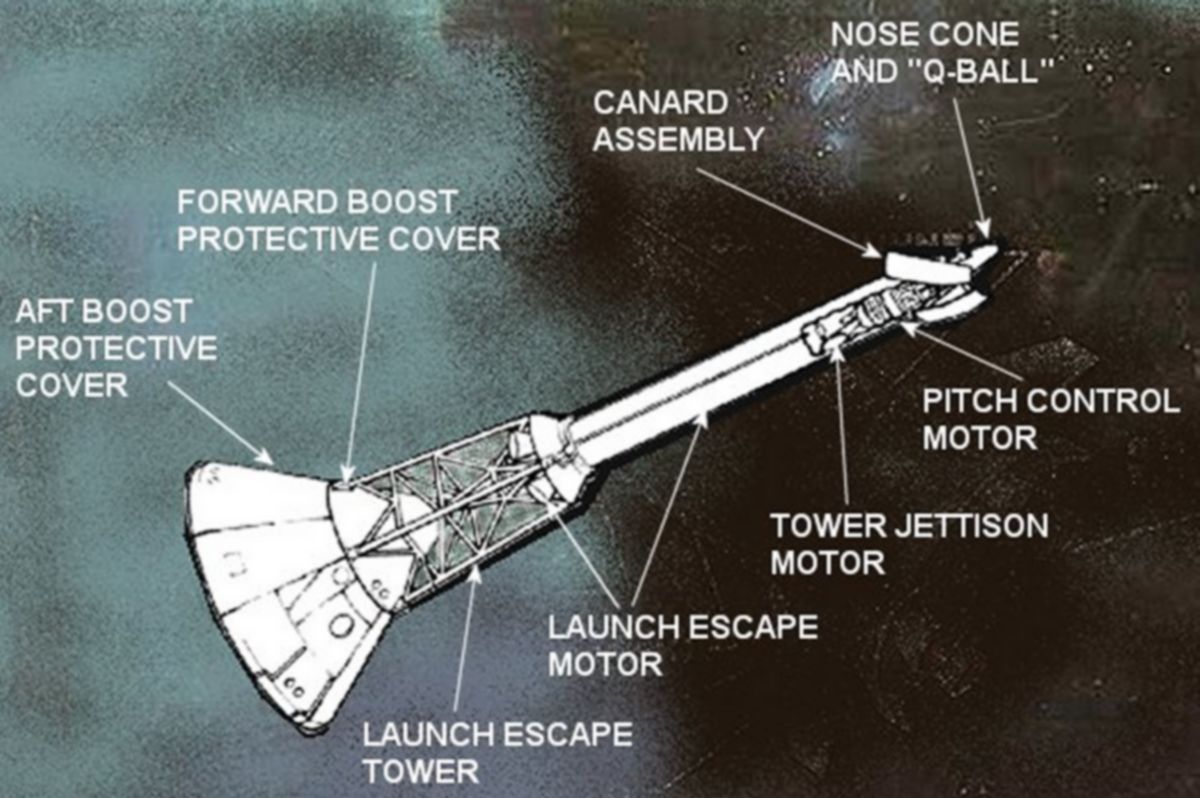
Sitting atop the Saturn V launch vehicle (LV) was the 82-foot tall Apollo spacecraft. Five components comprised it ‑ the launch escape system (LES), the command module (CM), the service module (SM), the lunar module (LM), and the spacecraft-lunar module adapter (SLA). The LES and SLA were jettisoned relatively early in the mission, after they had served their purpose. The LES was jettisoned after the first-stage burn ; the SLA was jettisoned after the third-stage translunar injection burn. |
 |
| Apollo Spacecraft |
The LES was a small rocket that carried the CM and its astronauts to safety if a LV malfunction occurred on the launch pad or during the first-stage boost phase.
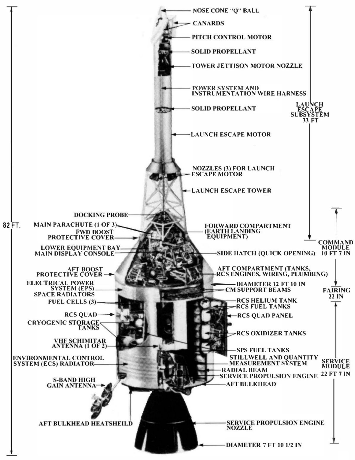
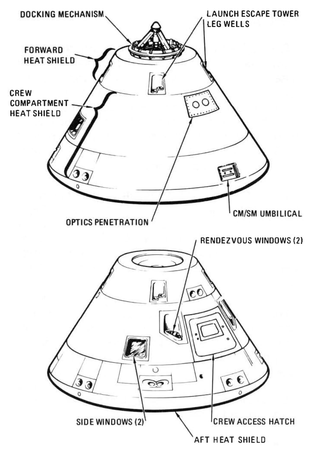
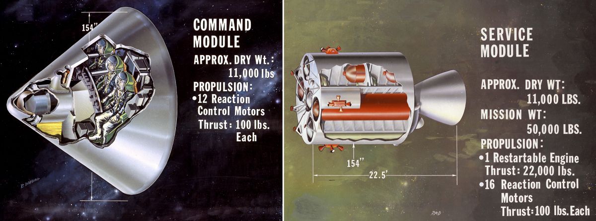
The CM was the spacecraft control center, providing living and working space for the three-man crew for the entire flight, except for the period when two persons were in the LM for descent to the moon and return. The CM was the only part of the spacecraft that returned to earth after the mission. The CM consisted of two shells, an inner crew compartment (pressure vessel) and an outer heat shield. The outer shell was a stainless steel honeycomb between stainless steel sheets, covered on the outside with a heat-dissipating ablative material that charred and fell away during earth atmospheric reentry. The inner shell was aluminum honeycomb between aluminum alloy sheets. A layer of insulation separated the two shells. This construction made the CM light yet rugged enough to withstand launch acceleration, the shock and heat of atmospheric reentry, the force of splashdown, and the possible impact of meteoroids.
Internally, the CM was a compact , efficiently arranged cockpit, office, laboratory, radio station, kitchen, bedroom, bathroom, and den. Its walls were lined with instrument panels and consoles, and its equipment and storage bays contained a wide variety of equipment. In flight, the cabin was air conditioned to a comfortable 70 - 75 °F, The 100 % oxygen atmosphere maintained a pressure of about 5 psi.
Although the crew could move about within the CM, much of their time was spent on their couches, which could be adjusted so the crew could stand and move around. Space by the center couch permitted two men to stand at one time. The couches were made of steel framing and tubing and covered with a heavy, fireproof fiberglass cloth. They rested on eight crushable honeycomb shock struts that absorbed landing impact. Control devices were attached to the armrests. The CM's controls allowed the crew to guide it during flight. Test equipment permitted spacecraft subsystem malfunction investigation. Television, telemetry and tracking equipment, along with two-way radio, provided communication with earth and among the astronauts during moon exploration and the moon orbit rendezvous. These and other subsystems, such as the reaction control, guidance and navigation, earth landing, and parts of the environmental control and electrical power, occupied almost every inch of available CM space.
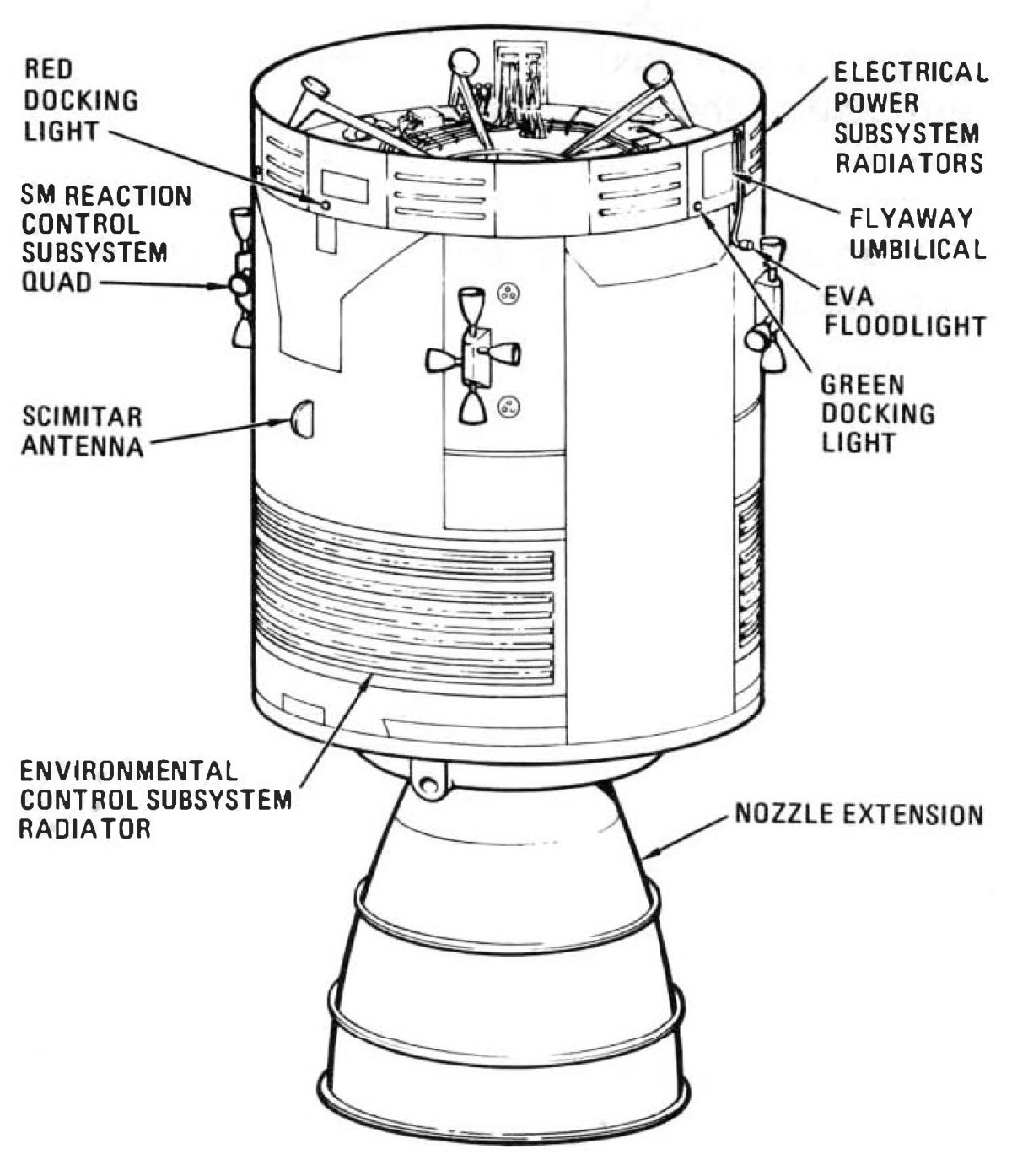
The SM was attached to the CM and supported the CM and its crew. Together the two modules were called the command/service module (CSM). The SM housed an electrical power generation and distribution subsystem, reaction control thrusters, part of the environmental control subsystem, and the service propulsion system (SPS). The SPS service propulsion engine was used for mid-course trajectory corrections, insertion into lunar orbit, and return from the moon. The SM was constructed of aluminum alloy. Its outer skin was aluminum honeycomb between aluminum sheets. Propellants (a combination of hydrazine and unsymmetrical dimethyl hydrazine as fuel and nitrogen tetroxide as oxidizer) and various subsystems were housed in six wedge-shaped segments surrounding the main engine. The SM was attached to the command module until just before earth atmosphere reentry, when the SM was jettisoned.
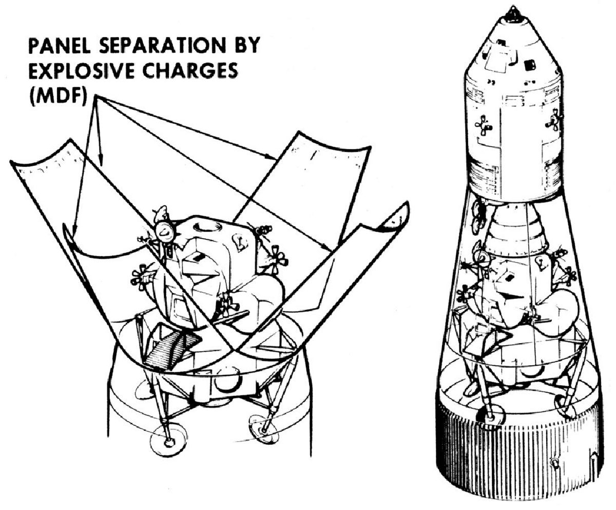
The SLA served as a smooth aerodynamic enclosure for the lunar module during boost and as the connecting link between the spacecraft and the LV.
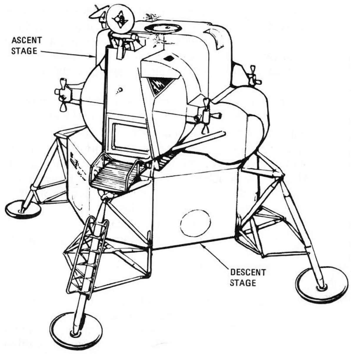
The LM carried two persons from the orbiting CSM down to the moon's surface, provided an operating base on the moon, and returned the crew to a rendezvous with the CSM in orbit. Its odd appearance resulted from the fact that there was no necessity for aerodynamic symmetry; the LM was enclosed during launch by the SLA and operated only in the vacuum of space or the moon. Two structures comprised the LM; the upper ascent stage and lower descent stage. The descent stage had a descent engine, propellant tanks, landing gear assembly, a section to house scientific equipment for use on the moon, and extra oxygen, water, and helium.
The ascent stage housed the pressurized crew compartment, the ascent engine and its propellant tanks, and all LM controls. It had the same subsystems found in the CSM, including propulsion, environmental control, communications, and guidance and control.
Portable scientific equipment carried in the LM included an atmosphere analyzer, instruments to measure the moon's gravity, magnetic field, and radiation, rock and soil analysis equipment, a seismograph, a soil temperature sensor, and cameras (including television).
 |
 |
 |
 |
 |
| Apollo Spacecraft | Command Module | Service Module | Lunar Module | Spacecraft-Lunar Module Adapter |
 |
 |
 |
 |
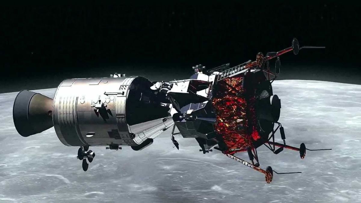 |
| Apollo Spacecraft | Launch Escape System | Command and Service Modules | Lunar Module | CSM and LM Docked |
--- On to Part 9.10, The Apollo Launch Escape System ---
Send mail to
![]() with questions or comments about this web site.
with questions or comments about this web site.
![]()