U.S. Manned Rocket Propulsion Evolution
Part 9.45: The Lunar Module Reaction Control System (RCS)
Compiled by Kimble D. McCutcheon
Published 28 Dec 2021; Revised 25 Jul 2024

Lunar Module Reaction Control System |
The Reaction Control System (RCS) provided thrust impulses that stabilized the LM and controlled attitude and translation during hover, landing, rendezvous, and docking. When the gimbaling descent engine was active the RCS provided roll control only. The RCS also provided thrust to separate the LM from the CSM and the +X-axis acceleration (ullage maneuver) to settle main propulsion system (MPS) propellants before a descent or ascent engine start. The RCS accomplished its task during coasting periods or while the descent or ascent engine was firing and operated in response to automatic control commands from the Guidance, Navigation, and Control Subsystem (GN&CS) or manual commands from the astronauts. |
Overview
Lunar Module Reaction Control System
Leading Particulars
| Pressurization Subsystem | |
| Helium Tanks | |
| Unpressurized Volume (each tank) | 910 in³ |
| Initial Fill Pressure and Temperature | 3,050 ± 50 psia at +70°F |
| Initial Helium Fill Weight (each tank) | 1.03 lb |
| Helium Temperature Range | +40° to +100°F |
| Proof Pressure | 4,650 psia |
| Diameter | 12.3" |
| Helium Filter Absolute Filtration | 12 microns |
| Primary Pressure Regulator |
| Output | 181 ± 3 psia |
| Lockup Pressure | 188 psia (maximum) |
| Secondary Pressure Regulator |
| Output | 185 ± 3 psia |
| Lockup Pressure | 192 psia (maximum) |
Pressure Regulator Assembly Flow Rate
(single thruster operation) | 0.036 lb/min |
| Relief Valve Assembly | |
| Venting Pressure | 232 psia |
| Reset Pressure | 212 psia (minimum) |
| Burst-Disk Rupture Pressure | 220 psia |
| Propellant Feed Subsystem | |
| Propellant Tanks | |
| Working Pressure | 174 psia |
| Proof Pressure | 333 psia |
| Propellant Pad Pressure | 50 psia |
| Propellant Storage Temperature Range | +40° to +100°F |
| Nominal Temperature | +70°F |
| Diameter | 12.5" |
| Oxidizer Tanks | |
| Volume (each tank) | 2.38 ft³ |
| Ullage Volume (each tank) | 273.0 in³ |
| Oxidizer Flow Rate to Each Thruster | 0.240 lb/sec |
| Available Oxidizer (each tank) | 194.1 lb |
| Oxidizer Loaded in Each System (tank and manifold) | 208.2 pounds |
| Height | 38" |
| Fuel Tanks | |
| Volume (each tank) | 1.91 ft³ |
| Ullage Volume (each tank) | 155.5 in³ |
| Fuel Flow Rate to Each Thruster | 0.117 lb/sec |
| Available Fuel (each tank) | 99.3 lb (minimum) |
| Fuel Loaded in Each System (tank and manifold) | 107.4 lb |
| Height | 32" |
| Propellant Filter Absolute Filtration | 18 microns |
| Ascent Feed Filter Absolute Filtration | 25 microns |
| Thrust Chamber Assembly |
| Engine thrust | 100 pounds |
| Engine Life | |
| Total | 1000 sec |
| Steady-State Mode | 500 sec |
| Pulse Mode | 500 sec |
| Restart Capability | 10,000 times |
| Chamber Cooling Method | Fuel-Film Cooling, Radiation |
| Combustion Chamber Pressure | 96 psia |
| Propellant Mixture Ratio | 2.05:1 |
| Oxidizer Inlet Pressure (steady state) | 170 ± 10 psia |
| Fuel Inlet Pressure (steady state) | 170 ± 10 psia |
| Approximate weight | 5.25 lb |
| Overall Length | 13.5" |
| Nozzle Expansion Area Ratio | 40:1 |
| Nozzle Exit Diameter | 5.75" |
| Heaters | |
| Type | Resistance-Wire Element |
| Operating Power | 28 VDC |
| Power Consumption (each heater) | 17.5 watts at 24 VDC |
|
 |
| RCS Thruster Quad |
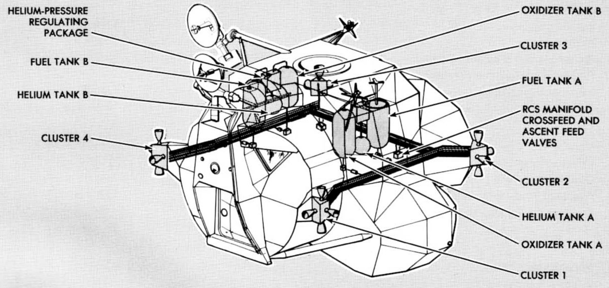
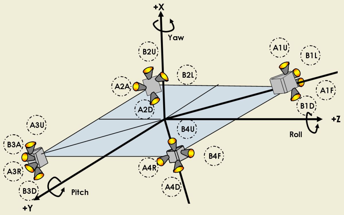
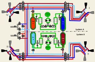
The 16 thrust chamber assemblies (thrusters), propellant and helium subsystems that comprised the RCS were located in or on the ascent stage. The propellants used in the RCS were identical to those used elsewhere in the LM ‑ nitrogen tetroxide oxidizer and Aerozine 50 fuel. The thrusters were small rocket engines, each capable of delivering 100 lbT. They were arranged in clusters of four, mounted on four outriggers equally spaced around the ascent stage. In each cluster, two thrusters were mounted facing in opposite directions, parallel to the LM X-axis; the other two were spaced 90° apart, in a plane normal to the X-axis and parallel to the Y- and Z-axis.
Two parallel, independent systems (A and B), comprised the RCS. Each system consisted of eight thrusters, a helium pressurization subsystem, and a propellant feed subsystem. Under normal conditions the two systems functioned together to provide attitude and translation control. The two systems were interconnected by a normally closed crossfeed arrangement that enabled the astronauts to operate all 16 thrusters from a single propellant supply. Complete attitude and translation control was therefore available even if one system's propellant supply was depleted or failed. Functioning alone, either RCS system could control the LM, although with slightly reduced efficiency. This capability was due to the thruster distribution because each cluster has two thrusters of each system located in a relatively different position.
In addition to the RCS propellant supply, the thrusters could use propellants from the ascent propulsion system. This required the astronauts to open interconnect lines between the ascent tanks and RCS manifolds, and was normally done only during periods of ascent engine thrusting as a means to conserve RCS propellants, which might have been needed during docking maneuvers.
Astronauts monitored RCS performance and state with their panel-mounted pressure, temperature, and quantity indicators, talkback flags, and caution/warning lights. These data originated at RCS sensors and position switches, were processed in the instrumentation subsystem, and were simultaneously displayed to the astronauts in the LM cabin and transmitted to mission controllers through MSFN via the communications cubsystem. RCS control was provided by the GN&CS, which determined operation modes, thruster selection, and firing duration.
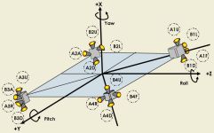 |
 |
| RCS Orientation |
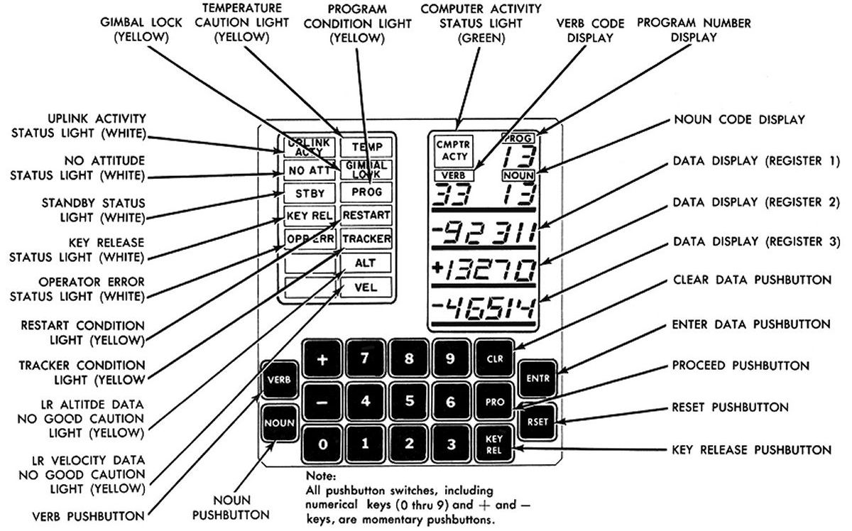
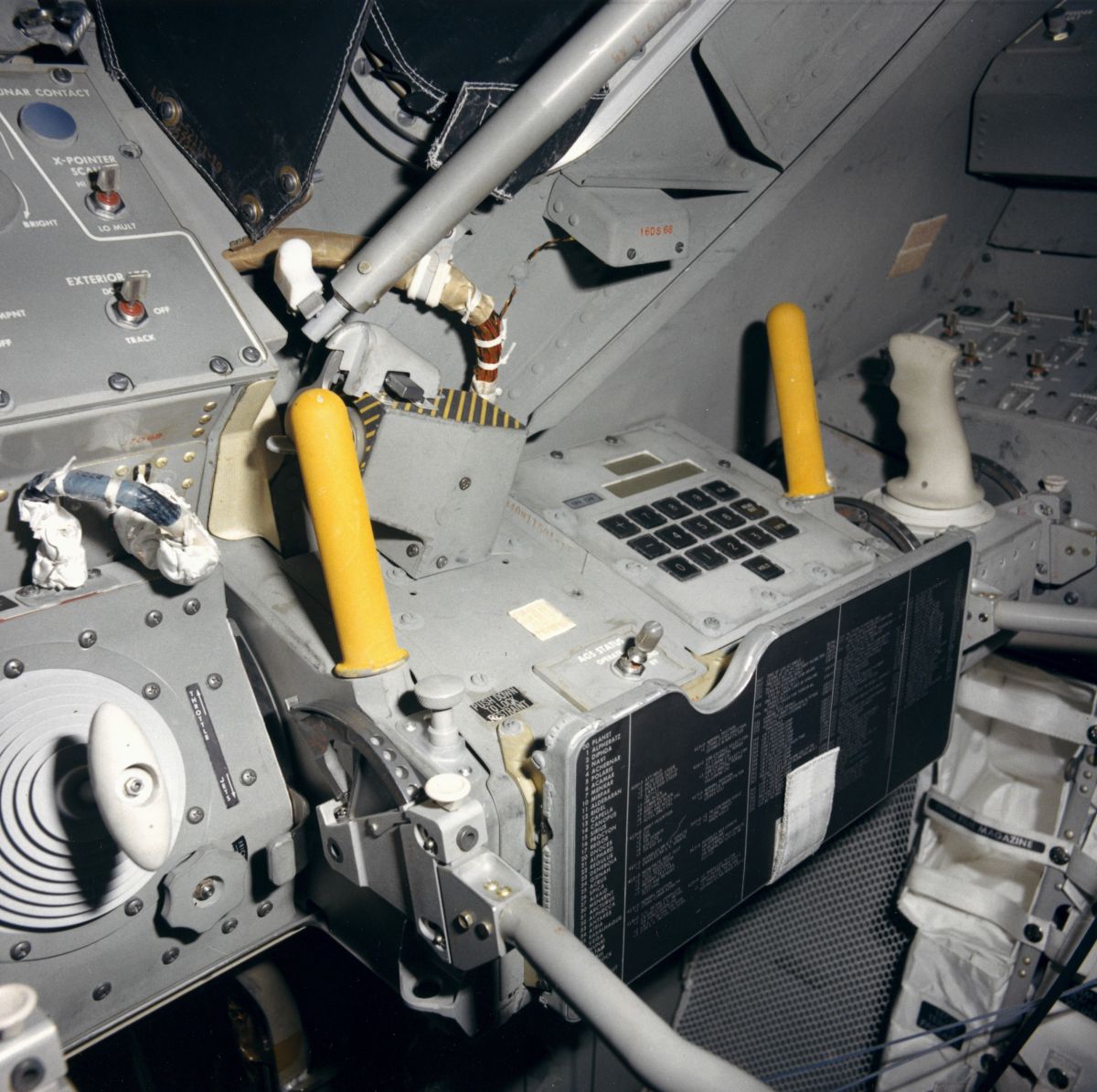
LM Display/Keyboard (DSKY) |
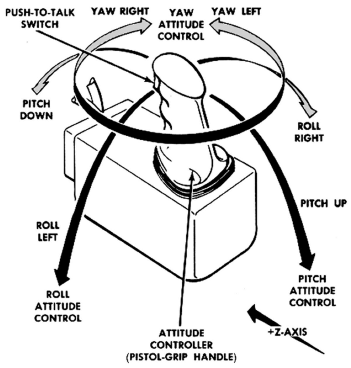
Lunar Module Reaction Control System Hand Controls
 |
 |
 |
 |
 |
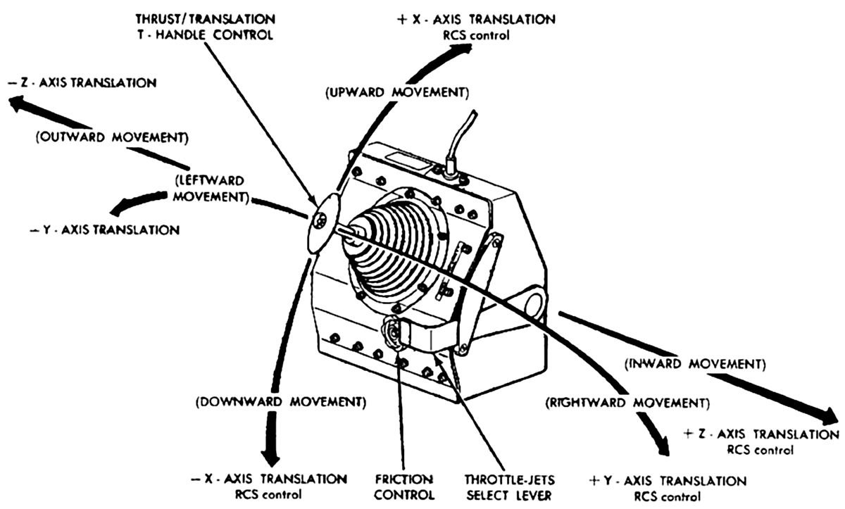
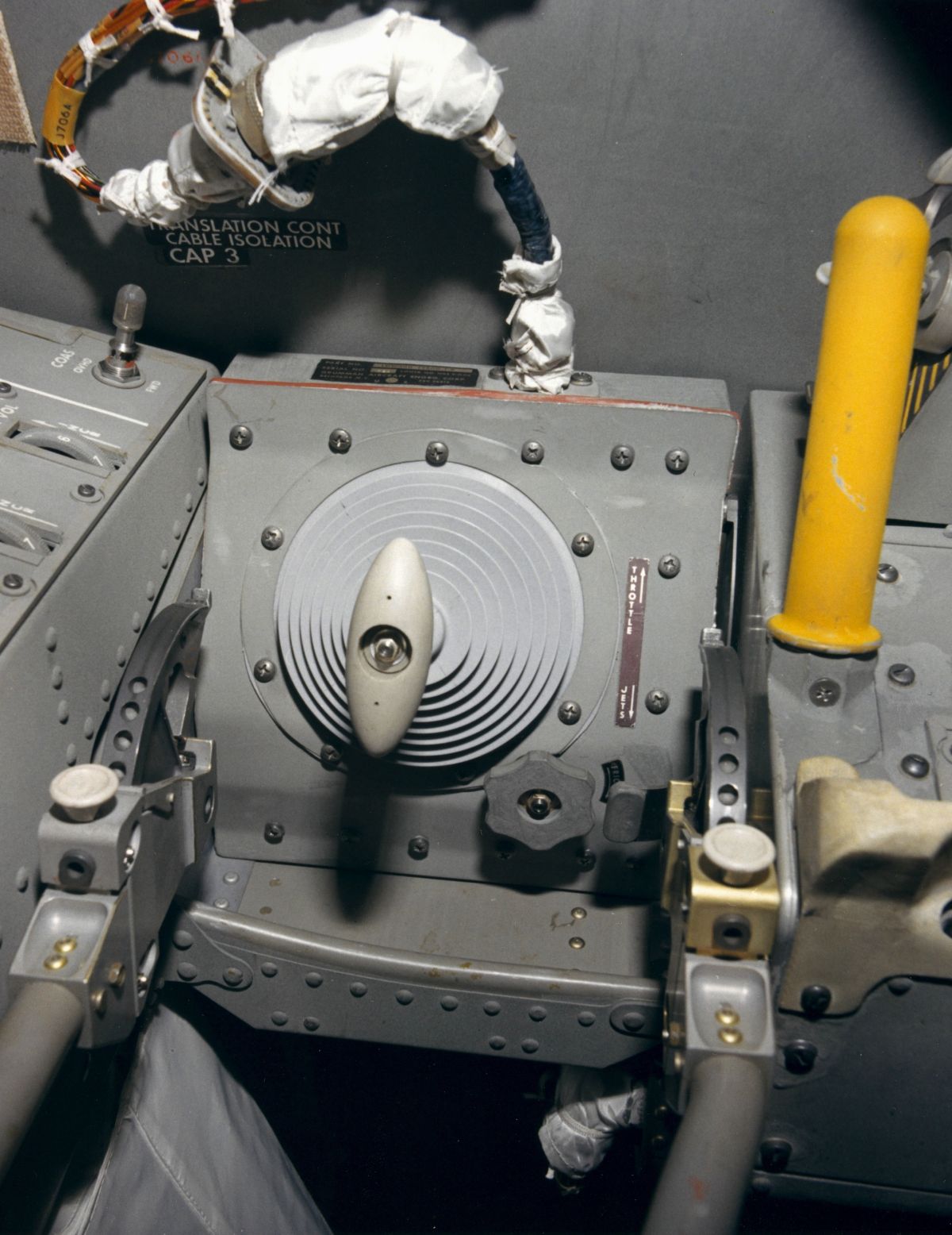
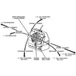
Translation/Thrust
Function |
Translation/Thrust
Controller |
LM Pilot's Station |
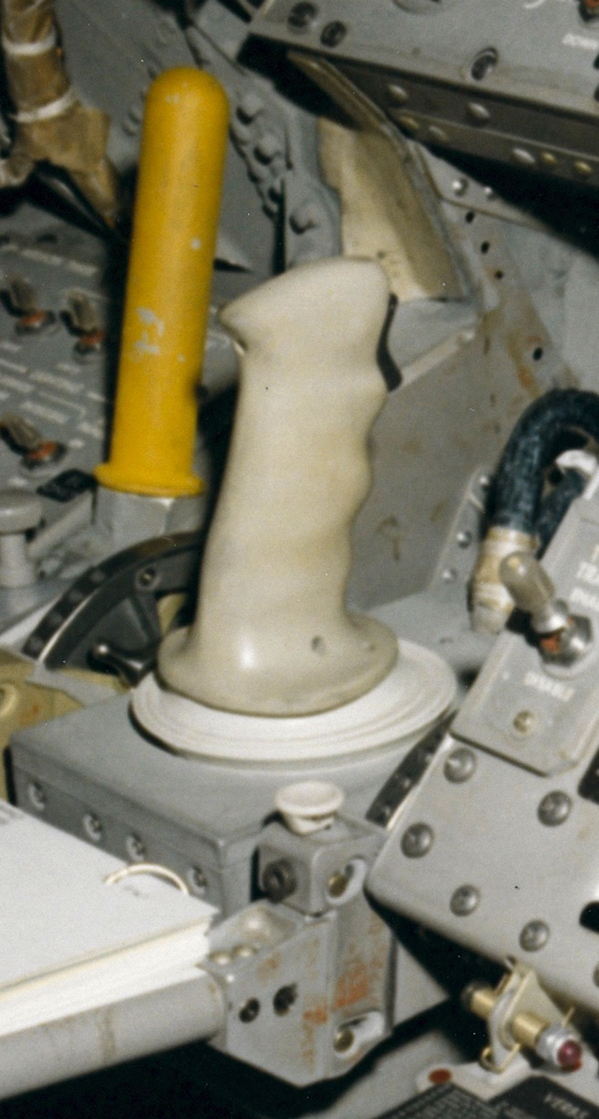
Attitude
Controller |
Attitude Controller
Function |
Functional Description
Thruster Selection, Operation, and Control
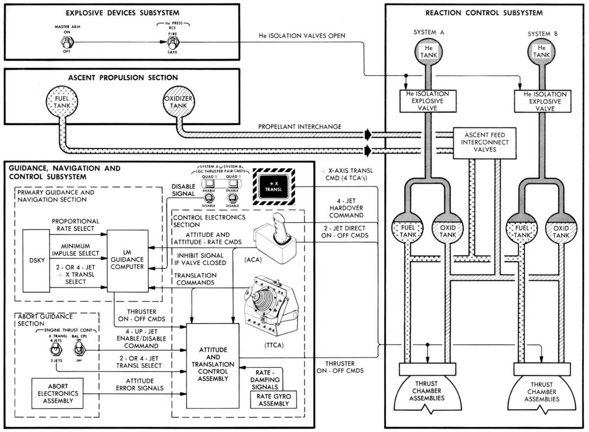
The GN&CS selected thrusters and fired them for durations ranging from short bursts to steady-state. The thrusters could be operated in automatic mode, attitude-hold mode, or a manual override mode. Normally, the RCS operated in the automatic mode; all navigation, guidance, stabilization, and steering functions were initiated and commanded by the LM guidance computer (primary guidance and navigation section) or the abort electronics assembly (abort guidance section).
The attitude-hold mode was a semiautomatic mode in which either astronaut could institute attitude and translation changes. When an astronaut displaced his attitude controller, an impulse proportional to the amount of displacement was routed to the computer, where it was used to perform steering calculations and to generate the appropriate thruster-on command. A DSKY input determined whether the computer commanded an angular rate change proportional to attitude controller displacement, or a minimum impulse each time the controller was displaced. When the astronaut returned his attitude controller to the neutral (detent) position, the computer issued a command to maintain attitude. For a translation maneuver, either astronaut displaced his thrust/translation controller. This sent a discrete computer command to issue a thruster-on command to selected thrusters. When this controller was returned to neutral, the thrusters ceased to fire.
If the abort guidance section was in control, attitude errors were summed with the proportional attitude controller rate commands and a rate-damping signal from the rate gyro assembly. The abort guidance equipment used this data to perform steering calculations, which resulted in specific thruster-on commands. The astronauts could select either two or four X-axis thrusters for translation maneuvers, and they can inhibit the four upward-firing thrusters during the ascent thrust phase, thus conserving propellants. In the manual mode, the four jet hardover maneuver, instituted when either astronaut displaced his attitude controller fully against the hard stop, fired four thrusters simultaneously, overriding any automatic commands.
For MPS ullage maneuvers, the astronaut selected whether two or four downward-firing thrusters were used. Depending on which guidance section was in control the astronauts entered a DSKY input (primary) or used a 2-jet/4-jet selector switch (abort) to make their selection Under manual control, a +X-translation push button fired the four downward-firing thruster continuously until the pushbutton was released. While firing two thrusters conserved RCS propellants, it then took longer to settle the MPS propellants.
RCS Subsystems
Functionally, the RCS could be subdivided into pressurization subsystems , propellant feed subsystems, and thruster subsystems. Because RCS systems A and B were identical, only one system is described.
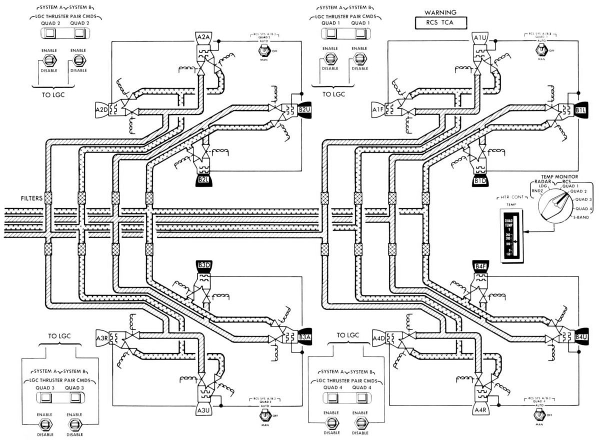
Fuel and oxidizer were loaded into bladders within the propellant tanks and into the manifold plumbing that extended from the tanks through the normally-open main shutoff valves up to solenoid valves at each thruster pair. Before the LM separated from the CSM, astronauts set control panel switches that preheated the thrusters and fired explosive valves to pressurize the propellant tanks. Gaseous helium, reduced to working pressure, entered the propellant tanks and forced fuel and oxidizer to the thrusters. Here the propellants were blocked by fuel and oxidizes valves that remained closed until a thruster-on command was issued. As the selected thruster received the fire command, its fuel and oxidizer valves opened to route propellants through an injector into the combustion chamber, where they impinged and ignited by hypergolic action. The astronauts could disable malfunctioning thrusters by operating appropriate LM Guidance Computer (LGC) thruster pair command switches on the control panel. When any of these switches were disabled, it issued a signal informing the LGC that the related thruster pair was disabled and that alternate thrusters had to be selected. Talkbacks above each switch informed the astronauts of the thruster-pair status.
Lunar Module Reaction Control System Diagrams
 |
 |
 |
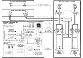 |
| Simplified Schematic |
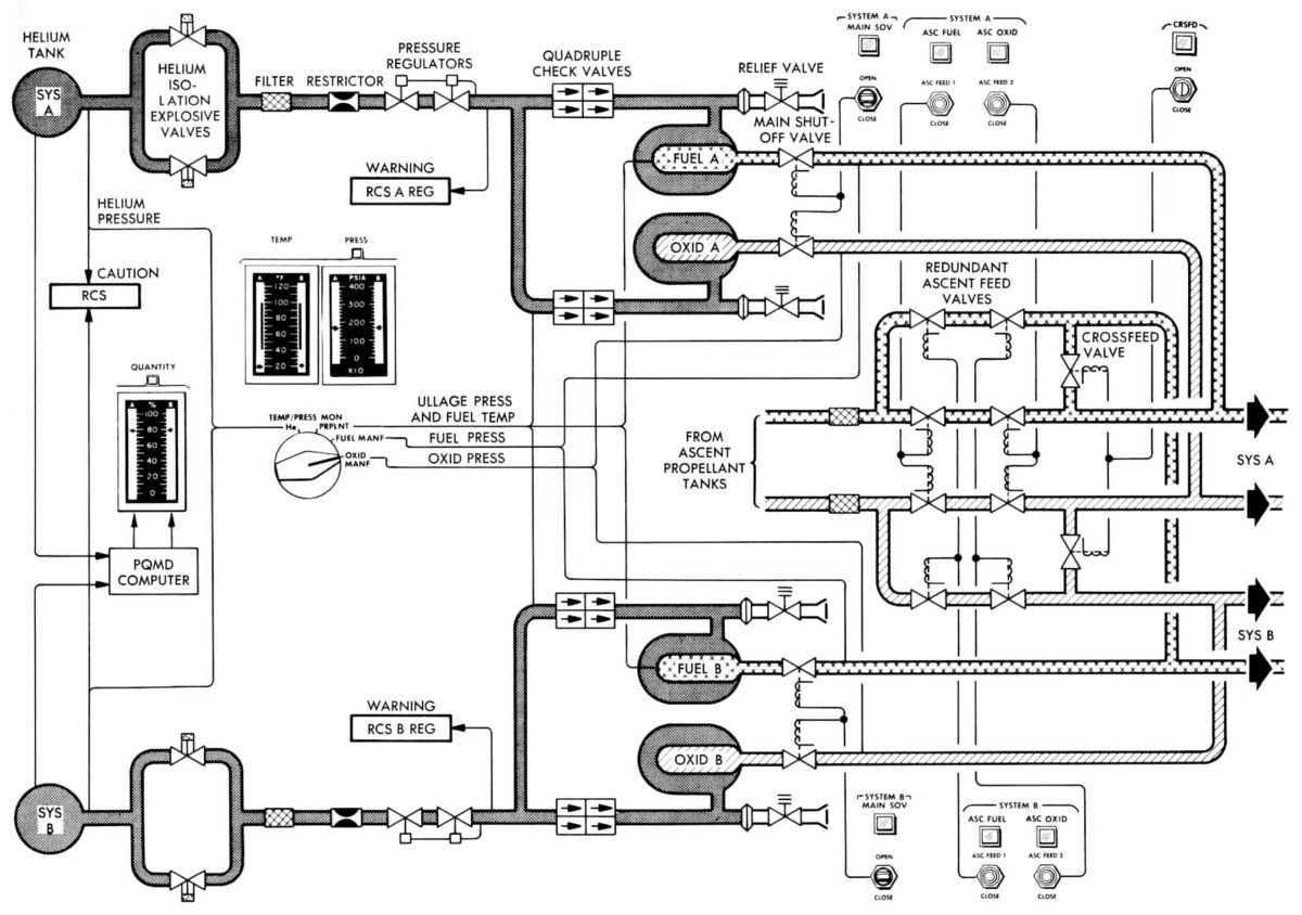
Pressurization and Propellant Feed Flow |
Thruster Flow |
Control |
Pressurization Subsystem
RCS propellants were pressurized with high-pressure gaseous helium. The helium tank outlet was sealed by parallel-connected, redundant helium-isolation explosive valves that maintained helium in its tank until the astronauts entered the LM and prepared the RCS for operation. When the explosive valves were fired, helium entered the pressurization line and flowed through a filter. A restrictor orifice downstream of the filter dampened the initial helium surge. Downstream of the restrictor, the flow path contained a pair of pressure regulators connected in series. The primary (upstream) regulator was set to reduce pressure to approximately 181 psia. The secondary (downstream) regulator was set for a slightly higher output (approximately 185 psia). In normal operation, the primary regulator was in control and provided proper propellant tank pressurization.
Downstream of the pressure regulators, a manifold divided the helium flow into two paths, one to the oxidizer tank and the other to the fuel tank. Each helium flow had quadruple check valves that permitted flow in one direction only, thus preventing propellant vapor backflow if seepage occurred in the propellant tank bladders. A relief valve assembly protected each propellant tank against overpressurization. If helium pressure built above 232 psia, the relief valve opened to relieve pressure by venting helium overboard. At 212 psia the relief valve closed.
Propellant Feed Subsystem
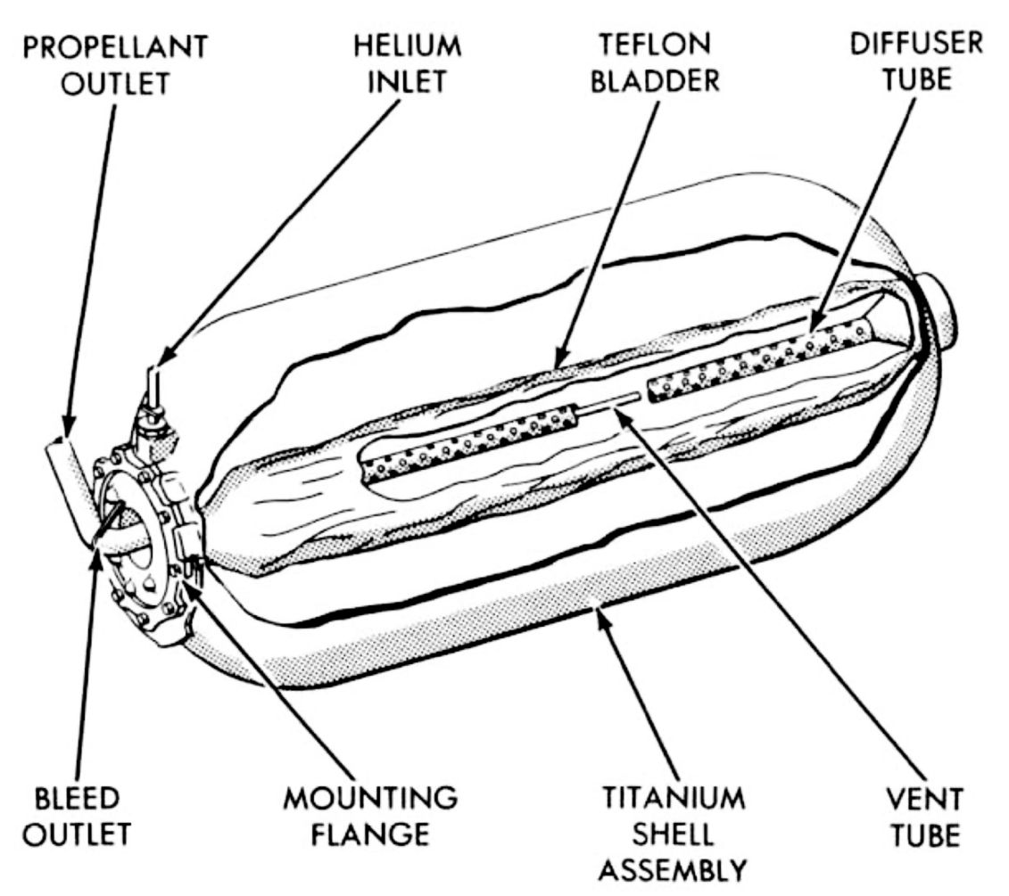
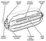 |
| Propellant Storage Tank |
Fuel and oxidizer were contained within flexible propellant tank bladders. Helium routed into the void between the bladder and the tank wall squeezed the bladder to positively expel propellants under zero-gravity conditions. The propellants flowed through normally-open main shutoff valves into separate fuel and oxidizer manifolds that led to the thrusters A switch on the control panel enabled the astronauts to simultaneously close a pair of fuel and oxidizer main shutoff valves, thereby isolating a system's propellant tanks from its thrusters if that system's propellants were depleted or if the system malfunctioned. After shutting off one system, the astronauts could restore operation of all 16 thrusters by opening the crossfeed valves between the system A and B manifolds.
During ascent engine firing, the astronauts could open the normally closed ascent propulsion subsystem/RCS interconnect lines if the LM was accelerating in the +X-axis (upward) direction. Closing the interconnect lines shortly before ascent engine shutdown ensured that no APS helium entered the RCS propellant lines. Control panel switches opened the interconnect valves in fuel-oxidizer pairs, for an individual RCS system, or for both systems simultaneously.
Transducers in the propellant tanks sensed helium pressure and fuel temperature. Due to the proximity of the fuel tank and oxidizer tanks, the fuel temperature was representative of propellant temperature. Quantity indicators for system A and B displayed the summed quantities of fuel and oxidizer remaining in the tanks.
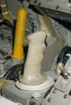
Thruster Subsystem
Each of the four RCS clusters consisted of a frame, four thrusters, eight heating elements, and associated sensors and plumbing. The clusters were diametrically opposed, evenly distributed around the ascent stage. The frame was an aluminum-alloy casting, shaped like a hollow cylinder, to which the four thrusters were attached; the entire cluster assembly was connected to the ascent stage by hollow struts. The vertical-firing thrusters were at the top and bottom of the cluster frames; the horizontal-firing thrusters were at each side. Each cluster was enclosed in a thermal shield, Part of the four thruster combustion chambers and their extension nozzles protrude from the shield. The thermal shields aided in maintaining temperature control for the propellant lines from the ascent stage to the thrusters, minimizing heat loss, and reflecting radiated engine heat and solar heat.
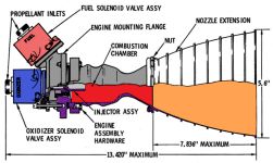 |
| Reaction Control System Thruster |
The R-4D RCS thrusters, supplied by the Marquardt Corporation of Van Nuys, California, were radiation-cooled, pressure-fed, bipropellant rocket engines that operated in a pulse mode to generate short thrust impulses for fine attitude corrections (navigation alignment maneuvers) or in a steady-state mode to produce continuous thrust for major attitude or translation changes. In the pulse mode, the thrusters were fired intermittently in bursts of less than one second duration. The minimum pulse could be a short as 14 milliseconds; however, the thrust level did not build up to the full 100 lbT that each thruster could produce. In the steady-state mode, the thrusters were fired continuously (longer than 1 second) to produce a stabilized 100 lbT until the shutoff command was received.
Two electric heaters, which encircled the thruster injector, controlled propellant temperature by conducting heat to the combustion chamber and the propellant solenoid valves. The heaters maintained the cluster at approximately +140°F, ensuring that the combustion chambers were properly preheated for instantaneous thruster starts. The astronauts could determine, by use of a temperature indicator and a related selector switch, if a cluster temperature was below the minimum operational temperature of 119°F and take corrective action to restore the cluster temperature.
Dual-coil, solenoid-operated shutoff valves at the fuel and oxidizer inlet ports prevented propellants from entering the thrusters. These valves were normally closed, but opened when an automatic or a manual command energized the primary or secondary coil, respectively. Several milliseconds after receiving the thruster-on command, the valves were fully open and the pressurized propellants flowed through the injector into the combustion chamber where ignition occurred. By design, the fuel valve opened two milliseconds before the oxidizer valve, to provide proper ignition characteristics. Orifices at the valve inlets metered the propellant flow to produce the correct oxidizer-to-fuel mixture ratio at the injector.
As the propellants mixed and burned, the hot combustion gases increased the chamber pressure, accelerating the gas particles through the chamber exit. The gases were expanded through the divergent section of the nozzle at supersonic velocity, eventually building up to reach a reactive force of 100 lbT in the vacuum of space. The gas temperature within the combustion chamber stabilized at approximately 5,200°F. The temperature at the nonablative chamber wall was maintained at a nominal 2,200°F by a combined method of film cooling (a fuel stream sprayed against the wall) and radiation cooling (dissipation of heat from the wall surface into space).
When the thruster-off command was received, coils in the propellant valves de-energized, and spring pressure closed the valves. Propellant trapped in the injector was ejected and burned for a short time while thrust decayed to zero.
When a thruster-on signal commanded a very short duration pulse, engine thrust was just beginning to rise when the pulse was ended and the propellant valves closed. Under these conditions, the thrusters did not develop the full 100 lbT capacity.
A failure-detection system informed the astronauts if a thruster failed on (fired without an on command) or off (did not fire with an on command). Either type of failure produced a warning light and a talkback. Astronauts then disabled the malfunctioning thruster pair by operating appropriate LGC thruster pair command switch and pulling associated circuit breakers (if thruster fail-on condition existed). To offset the effects of a thruster-on failure, opposing thrusters automatically received fire commands and kept firing until the failed-on thruster had been disabled. A thruster-off condition was detected by a pressure switch that sensed combustion chamber pressure. When a fire command was received, the thruster solenoid valves opened, resulting in ignition and subsequent combustion chamber pressure buildup. When the pressure reached 10.5 psia, the switch closed, indicating that proper firing was in process. When a very short duration (< 80 ms) fire command was received, the combustion chamber pressure might not have built up enough for a proper firing. Short pulse skipping did not result in a failure indication, unless six consecutive pulses to the same thruster did not produced a response. In this case, a warning light and talkback informed the astronauts of a non-firing thruster, which then had to be isolated.
Equipment
Explosive Valves
The explosive valves were single, cartridge-actuated, normally closed valves. The cartridge was fired by applying power to the initiator bridgewire. The resultant heat fired the initiator, generating gases in the valve explosion chamber at an extremely high rate. The gases drove the valve piston into the housing, aligning the piston port permanently with the helium pressurization line.
Propellant Quantity Measuring Device
The propellant quantity measuring device (PQMD), consisting of a helium pressure/temperature probe and an analog computer for each system, measured the total propellant quantity (sum of fuel and oxidizer) in the fuel and oxidizer tanks. The output voltage of the analog computer was fed to an indicator and was displayed to the astronauts on two scales (one for each RCS system) as percentage of propellant remaining.
The propellant quantity measuring device used a probe to sense the pressure/temperature ratio of the gas in the helium tank. This ratio, directly proportional to the gas mass, was fed to an analog computer that subtracted the helium tank mass from the system total mass, thereby deriving the helium mass in the propellant tanks. Finally, propellant tank ullage volume was subtracted from total tank volume to obtain the propellant quantity remaining. Before firing the helium isolation explosive valves, the quantity displayed exceeded 100%, so that, after the valves were opened and the helium tank gas became less dense, the indicated quantity was 100%.
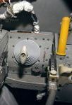
Propellant Storage Tanks
The four titanium alloy propellant tanks, one fuel and one oxidizer tank for each system, were cylindrical with hemispherical ends;. In each tank, the propellant was stored in a Teflon bladder, which was chemically inert and resistant to the corrosive action of the propellants. The bladder was supported by a standpipe running lengthwise in the tank. The propellant was fed into the tank from a fill point accessible from the LM exterior. A bleed line extending up through the standpipe drew off gases trapped in the bladder. Helium flowed between the bladder and the tank wall and acted upon the bladder to produce positive propellant expulsion,
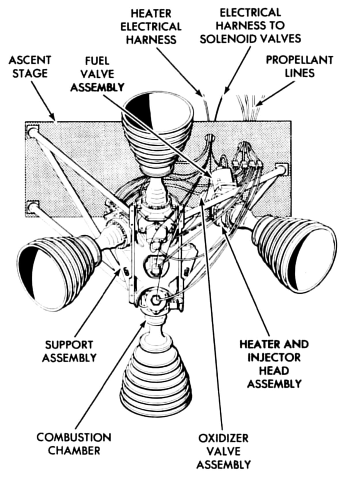
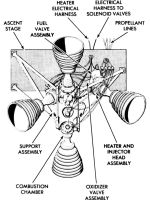
Thrust Chamber Assemblies
RCS thruster steady-state specific impulse was 281 seconds, and they produced a comparatively high thrust for their size with a fast response time. The thrusters also had a long cycle life, capable of being restarted many times. Each thruster consisted of a fuel valve, an oxidizer valve, an injector head assembly, a combustion chamber, an extension nozzle, and thruster instrumentation.
The fuel and oxidizer valves were normally closed, two-coil, solenoid valves that control propellant flow to the injector. Each valve had an inlet filter, an inlet orifice, a spool assembly, a spring, an armature, and a value seat. The primary and the secondary coils were wound on a magnetic core in the spool assembly. These coils receives the thruster on and off commands. The fuel and oxidizer valves were identical except for the inlet orifice, the valve seat, and the spool assembly. Because the ratio of oxidizer to fuel at the combustion chamber must be approximately 2:1, the diameters of the inlet orifices and the valve seat exits differed in the two valves. The fuel valve spool assembly produces a faster armature response, opening the fuel valve 2 ms before the oxidizer valve. Permitting fuel to enter the combustion chamber first reduced the possibility of ignition delay, which could cause temporary overpressurization (spiking) in the combustion chamber. Spiking was also held to a minimum by preheating and prepressurizing the combustion chamber.
When the thruster-off command was given, the coils de-energized, releasing the armature poppets. Spring and propellant pressure returned each valve's armature poppet to its seat, shutting off injector propellant flow.
The injector head assembly supported the fuel and oxidizer valves and the mounting flange for the combustion chamber. The injector propellant impingement and chamber cooling arrangement consisted of four concentric orifice rings and a pre-igniter cup. Initial combustion occurred in the pre-igniter cup (a pre-combustion chamber) where a single fuel spray and oxidizer stream impinged. This produced a smoother start transient because it raised the main combustion chamber pressure for satisfactory ignition. The main fuel flow was routed through holes in a tube to a chamber that channeled fuel to an annulus. The annulus routed fuel to three concentric fuel rings. The outermost ring sprayed fuel onto the combustion chamber wall, where it formed a boundary layer for cooling. The middle ring had eight orifices that sprayed fuel onto the pre-igniter cup outer wall to cool the cup. Eight middle-ring primary orifices ejected fuel to mix with the oxidizer. The main oxidizer flow was routed through holes in the oxidizer pre-igniter tube, to a chamber that supplied the eight primary oxidizer orifices of the innermost ring The primary oxidizer and fuel orifices were arranged in doublets, at angles to each other, so that that emerging propellant streams impinged. Due to the hydraulic delay built into the injector, ignition at these eight doublets occurred approximately 4 ms later than ignition inside the pre-igniter cup.
The combustion chamber was made of machined molybdenum, coated with silicon to prevent base metal oxidation. The chamber was cooled by radiation and by a fuel vapor film. The nozzle extension was fabricated from L605 cobalt base alloy. Eight stiffening rings were machined around its outer surface to maintain nozzle shape at high temperatures. The combustion chamber and extension nozzle were joined together by a large coupling nut and lock ring.
Engine chamber pressure switches, developed specifically for the LM RCS engines, were used in conjunction with the LM failure-detection system. The electrical signal from the guidance, navigation, and control system to the engine valves was compared electronically with the pressure switch output. If the two did not match, an engine failure indication was displayed to the crew, which could perform corrective action such as engine isolation or troubleshooting in other systems.
Heaters
Engine flange heaters, developed specifically for the LM RCS engines, were required to maintain the engine combustion-chamber flange temperature above +120°F, preventing Aerozine-50 fuel freezing during all mission phases. Two redundant, independently operating heating systems were used simultaneously to heat the RCS clusters. Two electric heaters, one from each system, encircled each thruster's injector area. The heaters normally operated in an automatic mode with redundant thermal switches (two connected in parallel for each thruster) sensed injector temperature and operated the heaters to maintain the desired temperature. The primary heating system heaters were powered directly from their circuit breakers. Power to the redundant heating system was routed through switches that allowed the astronauts to operate each cluster's heating system individually, either under automatic thermal switch control or with heaters continuously on or off.
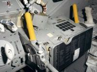
System Installation
Propellant and helium storage components were grouped in modules to simplify checkout and repair procedures. Both operations could be performed "on the bench" without impacting overall vehicle operations. The module was installed in two bay areas and on four outrigger booms. The tankage modules (helium, fuel, and oxidizer) were installed on the LM left- and right-hand sides directly above the APS tanks. The four-engine clusters were installed on the outriggers, which were located around the periphery of the ascent stage at 45° to the orthogonal (pitch and roll) axes. Two of the four engines in each cluster were fed from each propellant supply.
Development
The LM RCS was closely patterned after the SM RCS with common components used where possible. Where components could not be common, common technology was used. Experience gained from Gemini missions and the CSM RCS in the areas of system fabrication, checkout, and testing also was applied to the LM RCS. System reliability requirements were achieved through system and component redundancy. Two independent operational LM RCSs were provided.
The RCS propellant tankage of each system was sized to contain one-half the RCS propellant required for descent, plus the total RCS propellant required for ascent. In addition, a contingency propellant supply was provided through an interconnect arrangement between the ascent propulsion system propellant tanks and the RCS manifolds. The interconnect arrangement originally was meant to be used only in an emergency situation. However, the interconnect arrangement was used as a normal operating mode during the powered-ascent phase to conserve RCS propellants for docking contingencies.
Redundant components, such as regulators, check valves, and explosive pressurization valves, were used with each pressurization system. The explosive valves were in a parallel configuration because the primary failure mode was in a closed position. The regulators were in a series arrangement because the primary failure mode was in an open position. The check valves were arranged in a series-parallel configuration (1) because the failure probability in an open or closed position was considered to be about equal and (2) because the weight penalty associated with this particular component was minimal. Thus, no single functional failure could impair the spacecraft control or jeopardize crew safety because of propellant shortage.
The common-use philosophy was applied throughout the system design, using developed CSM components wherever possible. Whenever the component could not be used directly, but could be made usable on the LM with minor modification, a common-technology approach was followed. The manufacturer of the SM part was given the task of modifying his product to make it usable on the LM. Because this approach permitted the use of the same test procedures, test equipment, and personnel employed for the SM, the resources and learning time required to produce a given piece of hardware were minimized and, thus, significant cost savings and increased confidence in reliability resulted.
Testing and Certification
Nine major ground test programs comprised LM RCS development and certification. Each test program is discussed below.
The preproduction system development test program, or breadboard test, was the first test in which the proposed LM RCS configuration was hot fired. The term "configuration" is emphasized here because the propellant-feed plumbing geometrical configuration, which was the most important test item, was nearly the only test hardware that resembled actual flight hardware. Excepting the very early prototype engines, the breadboard system was composed of commercially available industrial-type components.
In early 1964, when the breadboard was being assembled, most flight components were still in early development stages and were rather scarce. Most components were being developed under a common-usage agreement, and those few parts made available to the LM program were being installed on LM-1 and on major test vehicles. The breadboard testing, conducted by the RCS engine developer between August 1964 and May 1965 investigated the propellant-feed system dynamic characteristics. The maximum engine pulse-frequency requirement was 25 pulses/sec at a pulse duration of 10 milliseconds. This high pulse frequency caused concern that relatively long LM propellant feedlines could not maintain adequate engine inlets pressure during transient flow. Also evaluated were propellant-manifold priming procedures and engine performance during multi-engine firings. One other important program aspect was "shaking down" the new custom LM test facility and data-acquisition equipment.
The firing program consisted of single and multiengine firing matrices covering a wide range of pulse widths, pulse frequencies, and predicted flight duty cycles. The effects of pulse firings on the steady-state performance of another engine in the same system also were investigated. Almost 15,000 separate firings totaling about 8,000 burn-time seconds of were accumulated on the eight-engine system. The breadboard configuration provided valuable data much earlier than would have been possible if the test program had depended on flight hardware as the test program was completed almost a year before the first flight configuration was available for testing.
A significant test program finding was that feed pressure fluctuations during short-pulse high-frequency firing were more severe than had been predicted analytically. In certain pulse modes, the transient engine-inlet pressures dropped to levels as low as the propellant vapor pressure, in which case the engine produced no thrust. Peak transient pressure generated at engine valve closure also approached the some components' proof-pressure ratings. Fortunately, these detrimental feed-pressure fluctuations were recognized early and serious LM program effects were avoided. This information led to a complete reevaluation of LM control system requirements and helped define the guidance system/RCS interface and resulted in a maximum pulse frequency change from 25 to 7 pulses/sec. Another significant breadboard testing conclusion was that the planned propellant manifold filling and priming techniques produced excessive transient pressures, some occasionally greater than the design flight component burst pressure. Most propellant-feed system component were rated at 550 psia burst-pressure; during filling and priming with nominal operating tank pressures, transient pressures as high as 1,100 psi were recorded. These data caused the flight-activation procedure to be changed from priming with full system operating pressure to priming at tank pad pressure, before activating the helium-pressurization system.
The
production system development test program was conducted from August to November 1966 using the HR-3P test rig, which was almost identical to the LM-1 RCS. The test program sought to determine if the RCS could achieve its fundamental design requirements. The HR-3P test rig also provided valuable helium and propellant servicing experience, which was used in spacecraft launch-site ground-support equipment design. Most test rig components were pre-qualified or qualified versions that had been extensively tested as individual components. To facilitate efficient test operations, the program was divided into a series of short tests, each with a specific objective relating to the various environmental or operational conditions that a flight system might experience during a lunar landing. Also, anticipated flight conditions were simulated whenever possible within the operational limitations of the test facility and the imposed schedule requirements. All tests were performed at local barometric pressure, which was approximately 12.5 psia. A large number of specific test objectives investigated the following items:
- Helium-pressurization-system activation and propellant section priming.
- System performance during simulated vehicle control modes and mission duty cycles.
- High and low temperature effects on system performance.
- System performance during crossfeed and simulated interconnect operation.
- System-malfunction procedure effectiveness and component redundancy.
- Component propellant compatibility.
- Decontamination techniques, equipment, materials and fluids.
Single and multiengine firings under nominal and off-nominal propellant-feed pressure conditions, engine valve voltages, and propellant temperatures comprised the firing program. The program accumulated approximately 57,000 separate engine firings totaling 8,300 burn time-seconds. Except for rather routine instrumentation and support facility operational problems that are usually expected during a complex and large-scale test operation, the program ran rather smoothly and was completed expeditiously. All test objectives were accomplished and no insurmountable deficiencies were uncovered. The unique system operation environment did disclose salient component characteristics that were not compatible with all planned system operational modes. An outstanding example was the discovery that the propellant latching valves would unlatch and shift position when subjected to the high flow rates or pressure surges that occurred during initial propellant manifold filling or priming. This problem spawned a very comprehensive investigation into latching valve design and revealed its true limitations. This valve problem was solved by requiring the flight crew to ascertain correct valve positions during critical flight phases . Other component problems discovered were incompatibility of transducer diaphragms with residual combusted propellants and inadequate seal design in the ground half of the propellant-servicing quick-disconnect couplings.
The production system development test program also revealed that system contamination control procedures were incompatible with some components' design and reliability requirements. Almost every system component and many facility components experienced leakage caused by particulate contamination. The propellant latching valve, because of a very narrow (0.006") seat, was particularly sensitive to contamination. The large number of particulate contamination leaks resulted in a broad-based contamination control program.
The design verification test (DVT) test program, executed during February and March 1967, verified flight system operation, manufacturing and checkout procedures, contamination control techniques, and propellant decontamination procedures. All DVT system components were fully-qualified versions and were assembled into the LM-3 configuration, which was the first manned vehicle. The DVT program repeated parts of the production system test program. High and low propellant-temperature tests, crossfeed operation, and simulated failure-mode operation tests were conducted. Approximately 23,200 engine firings totaling about 3,800 engine-burn time seconds.
The production cluster environmental test program demonstrated the engine cluster and vehicle mounting hardware structural integrity. Extensive shock and vibration tests along all major axes were conducted on a complete production flight engine cluster and boom assembly. With the exception of a chamber pressure transducer bracket failure, the cluster design withstood all the mission-level random and sinusoidal vibration loads. Overstress vibration levels of up to 200% did not cause any significant structural failures. The failed transducer bracket was redesigned and was retrofitted on LM-1.
The LM production cluster firing test program, involving firing a complete flight worthy four-engine LM engine cluster under simulated altitude conditions, occurred during the production cluster firing test program in April 1966. The program evaluated engine performance under realistic low-ambient-pressure flight conditions to determine cluster heat-transfer characteristics during steady-state and pulse-mode duty cycles. These data were integrated into the cluster thermal tests that were conducted in a thermal vacuum facility that simulated the space environment. The firing program consisted of single and multiengine firings that simulated selected mission duty cycle portions for 8,500 firings and 1,807 burn time seconds.
On 27 Apr 1966, during a low-temperature mission duty cycle test program, an upfiring engine combustion chamber exploded during a pulse start, which resulted in immediate program termination and the initiation of an extensive failure-analysis effort. The failure was caused by several factors including the upfiring engine attitude, low engine temperature, propellant helium saturation, short-pulse firings, and relatively high test-cell ambient pressure. These led to nitrate compound accumulation, which could cause high ignition overpressures and injector-manifold explosions. The failure brought about an extensive engine requalification program but did not result in any engine design changes. For the CSM application, the engine was qualified with monomethyl hydrazine fuel. For the LM application, the requalification was done with Aerozine 50 because of the same fuel was used for the LM RCS and APS. When the engine flange temperature was maintained above 120°F, failure was unlikely, so the cluster heater design was changed to ensure 120°F flange temperature.
The integrated RCS/APS PA-1 test program test rig was a flight-weight ascent-stage structure with only the RCS and APS installed. It was built principally for development testing of the APS, and the RCS was included primarily for evaluating the interconnect-propellant-feed mode. The PA-1 RCS configuration was similar to the HR-3P test rig and LM-1 except that solenoid valves were installed between the propellant tanks and the helium module to prevent propellant vapor migration into the regulators and check valves during extended downtimes. Also, additional feedline access ports were installed between the cluster isolation valves and the engines to aid in draining propellant. All testing was conducted at the NASA White Sands Test Facility (WSTF) during September and October 1966. An 11-run test series was made under the altitude conditions (88,000 to 140,000 feet) attainable with the WSTF vacuum pumping system. Approximately 3,000 firings and 515 burn-time seconds were accumulated on 12 engines. The four upfiring engines were disabled to prevent possible injector-manifold explosions, which could have occurred at the relatively high test-cell pressure, which was not a realistic space vacuum simulation. Neither the RCS nor APS experienced any detrimental effects during the interconnect-feed operation. A very minor decrease in RCS engine thrust, estimated to be 1 – 2%, was observed while propellant was being supplied from the APS. This condition was attributed to slightly lower engine inlet pressures resulting from increased pressure loss through the longer feedlines. The propellant pressure transients generated during RCS engine pulsing had little or no influence on APS engine performance.
As in earlier system test programs, contamination control was the only system-oriented problem that arose. Almost all the propellant latching valves experienced internal leakage and before testing began, all engines had to be returned to the manufacturer for cleaning. A proposed flight procedure demonstrating the venting of RCS propellant manifolds of the nitrogen launch-pad pressure by opening the engine valves at high altitude was unsuccessful. Gross propellant leakage through either the interconnect valves or the main shutoff valves resulted in hot firings during the attempted manifold venting. As a result of this test and numerous latching valve leaks, the LM-1 manifold venting operation was eliminated.
RCS testing on PA-1 resumed with series 8, 11, and 12 tests, starting in July 1968 and ending in May 1969. The major emphasis during PA-1 series 8 testing was to test the APS and RCS in support of the first manned flight (LM-3). The RCS engines were operated in normal-feed, crossfeed, and interconnected feed modes. All tests were conducted at simulated altitude conditions. The test-cell pressure was maintained below the 0.2-psia red-line value based on engine test experience; therefore, the upfiring engines could be fired. Testing consisted of base-line engine performance tests with various propellant-feed modes, high-altitude start testing, and selected firing matrices designed to evaluate the integration of the RCS and the caution and warning electronics assembly (CWEA).
Conclusions from series 8 tests included:
- RCS performance in the various feed modes was acceptable.
- Safe RCS start capability and acceptable engine performance at high altitude (220,000 feet) were demonstrated.
- The NASA John F. Kennedy Space Center servicing procedures should be modified to include a continuous powering (open) of the main shutoff valves during RCS manifold priming. All other priming and pressurization procedures were acceptable.
- Hydraulic interactions between the APS and RCS during interconnect feed caused minor fluctuations in the ascent-engine chamber pressure.
- The integrated RCS/CWEA performed satisfactorily.
During series 11, RCS engines were operated in the interconnect-feed mode (APS propellants) throughout the series to simulate the ascent portion of the lunar mission. Testing consisted of a shakedown firing, an off-nominal lunar-landing-mission duty cycle to evaluate the extent of RCS-induced ascent-engine chamber pressure fluctuations, and subsequent heat-soakback tests to simulate various failed RCS engine configurations. Series 11 testing indicated a potential problem with trapped propellant pressure rise in the inlet manifolds because of thermal soakback from a hot engine. In these tests, thruster-pair isolation valves were closed and the RCS heater was turned off after RCS firing activity. In several cases, engine heat soakback and the concomitant thermal expansion of the trapped propellants resulted in inlet pressures up to the maximum allowed (700 psia in this test). The rate of pressure buildup showed that 700 psia would have been exceeded had the thruster-pair isolation valves not been opened for relief; consequently, the Apollo malfunction procedures incorporated pressure relief steps ‑ firing of one of the two isolated engines after isolation of an engine pair.
Series 12 testing was a shakedown firing, a simulated ullage burn (in support of the LM-3 APS anomaly investigations), an off-nominal lunar-landing mission duty cycle (high-frequency RCS pulsing), and subsequent heat-soakback tests. It was concluded from series 12 testing that high-frequency RCS pulsing (up to 11 pulses/sec) did not initiate CWEA thrust chamber assembly failure indications in either the normal- or interconnect-feed modes. Furthermore, high-frequency RCS pulsing did not seriously degrade engine performance, although the effect was greater in the interconnect mode than in the normal-feed modes.
A complete
in-house LM RCS test program was conducted at the NASA Manned Spacecraft Center (MSC) in December 1967. This test defined the general LM RCS operational characteristics under simulated altitude conditions and obtained performance data on individual subsystem components. This system test was the first conducted at simulated altitudes in excess of 100,000 feet. The test article included all qualified components except combustion-chamber pressure switches. Most system components and all propellant lines had been used previously on the HR-3 DVT, but the HR-3 DVT configuration was modified and updated as required to satisfy specific test objectives and to incorporate the latest flight system changes, which included:
- Propellant-quantity-measuring devices were installed in each helium tank.
- One flight thruster heater was installed on each engine.
- A propellant filter was installed in each engine injector valve.
- A non-flight pressure switch was installed in the16 engine injector heads.
- Flight arc-suppression circuitry was installed on each engine.
- The test program included pretest operations, base-line performance duty cycles, simulated LM-1 and lunar-mission duty cycles, special "worst-case" duty cycles, and post-test checkout and decontamination.
The primary test objectives were satisfied and data on the general LM RCS operational characteristics were obtained. Anomalies, which were investigated and resolved, included propellant latch valve leakages, pressure switch failures, and engine injector cooling below the 120°F lower limit. Propellant latch valve leakage was caused by particulate contamination, again emphasizing the need for system cleanliness. Failed-closed switch failures were traced to switch mechanism contamination by the semi-liquid combustion products, which trashed the switch but did not lead to serious problems. Failed-open switch failure were caused by a design deficiency that was corrected on the flight hardware. The injector cooling problem was traced to aggressive test engine duty cycles, which did not occur on normal missions. The HR-3 DVT system components performed within specification after testing at the subcontractor's plant and storage for several months. Following the test program, the system completed a subsequent test program (LM-1 anomaly investigation) after a 4.5-month exposure to an unknown and uncontrolled propellant concentrations.
Heater integration tests were performed after the engine was requalified with Aerozine 50 fuel at 120°F flange temperature. A complete four-engine cluster with eight engine flange heaters was subjected to numerous firing duty cycles. Combinations of short pulses caused the engine flange to cool faster than the heaters could warm it. In some cases, the cooling effect was so severe that the flange temperature dropped to below 100°F, and an engine explosion finally resulted. Additional test runs identified the flange cooling regimes. Engineers recognized that many test duty cycles were much more severe than expected flight duty cycles. However, since actual flight duty cycles were highly unpredictable, it was necessary to establish the safe operating regime. The result was a map defining safe and unsafe engine operating duty cycles. Concurrent with the engine tests, additional mission simulations were performed to obtain a better estimate of safe flight duty cycles. The mission operating envelope (automatic mode) was found to be well within the safe region. The cooling effect was not a problem in the manual command mode because short-pulse combinations were not possible.
During the LM-3 mission, engine cluster temperatures exceeded not only the predicted values but also the cluster instrumentation upper limit. An engine valve temperature test series was conducted in April 1969 to define the maximum temperature to which the engine valves could be subjected without performance degradation. The engine was tested at ever-increasing temperatures starting at 275°F and ending at 375°F. The tests were terminated at 375° F when no degradation in performance was experienced. An instrumentation change increasing the upper limit from 200°F to 260°F was made.
RCS Flight Vehicle Checkout
LM RCS checkout was divided into four test categories that were conducted during various vehicle buildup stages. These were component tests, module tests, system-level tests, and vehicle-integration-checkout tests. In general, all individual component tests at each checkout level were the same. Also, most test and success criteria were patterned after component pre-delivery acceptance tests, which were derived from the original component procurement specifications. The various checkout tests performed during vehicle buildup provided increased confidence in the system and permitted the tracking of component performance from one test to another so that any degradation could be detected easily.
Component tests were conducted at the component manufacturer’s plant and at final assembly just before vehicle installatione. The pre-installation test (PIT) was repeated the component manufacturer’s checkout with some of the less important tests eliminated. As the program progressed and more experience and confidence were gained, the PIT scope was decreased gradually and in some cases eliminated entirely. The PIT was informal, consisting of proof-pressure tests, external and internal leak tests, cleanliness verifications, and functional checks. Each test was conducted according to a test plan or outline that did not call out each individual operational step, and these documents did not require quality control and inspection rigor of higher-level test procedures. Informal test procedures were the most significant PIT operational flaw and resulted in the introduction of particulate matter, numerous helium-relief-valve burst disk ruptures, and propellant latching valve position indicator switch shorting. However, the PIT did eliminate many faulty units before they could be installed on the vehicle.
Module level checkout was conducted on assemblies consisting of two or more components. Interconnecting brazed joints and plumbing were proof and leak tested, and the standard checks on individual components were repeated. The module-checkout concept increased checkout operation efficiency by substantially reducing procedure and test equipment complexity. For example, the elaborate and time-consuming precautions required that prevented propellant tank bladder flexure during regulator and relief valve checkout were completely eliminated in the helium-module checkout by performing it without the tankage module attached. The module-test concept also allowed flexibility in the checkout flow, with various modules being checked out independently without constraining other checkout functions. Other items checked as modules were cluster isolation-valve/filter assemblies and propellant manifolds. Tankage-module checkout consisted of bladder leak checks, unlatch current measurement, main shutoff valve leak tests, and brazed joint proof/leak tests on completely assembled and tested helium module and tanks. Final instrumentation checks produced complete tankage modules ready for vehicle installation.
Concurrently with tankage-module checkout, the propellant manifolds were installed and verified clean by a liquid Freon flush. This cleanliness test was conducted in two stages, with the first verifying the plumbing between the tankage module outlet to the cluster filter inlet, and the second verifying the entire manifold cleanliness up to the engine inlets. This liquid-flush cleanliness verification came about only after gaseous verification proved totally inadequate. The flushing procedure effectiveness was enhanced by simultaneous low-level vibration of the plumbing. Engine valve and propellant latch valve leaks were reduced drastically by the liquid-flush techniques.
System-level tests consisted of manifold integrity tests, engine leak tests, and engine gas flow tests. Some helium-module components, which were susceptible to degradation by other functions or by time, also were retested. A rather unique test tool called a "calibrated feather" was used to qualitatively verify gas flow through each individual engine injector head propellant orifice.
Vehicle integration tests, usually conducted just before vehicle shipment, verified the interfaces between the RCS and other systems. Engine valve wiring and response, cluster heater current draw, and instrumentation were checked during the factory checkout final phase.
LM RCS Flight Performance
LM RCS performance on all Apollo flights was satisfactory. Several minor problems occurred, but satisfactory solutions were found. The LM-1 and LM-3 flights indicated that the engine cluster upper temperature limit of 190°F was exceeded on numerous occasions with no deleterious effects. As previously discussed, additional vendor test data demonstrated that the engine valves could be safely operated at a much higher temperature. Consequently, the limit was deleted on LM-4 and subsequent vehicles.
Pressure switch "closed" failures occurred during the LM-3, LM-4, and LM-5 flights, but these failures had no significant effect on the flights because the only consequence was the loss of capability to detect an engine "off" failure. The single pressure switch "open" failure that occurred intermittently on LM-5 was considered to be a serious problem because an erroneous thrust chamber assembly (TCA) failure indication resulted. This problem was solved on subsequent missions by briefing the crews about potential erroneous TCA flags. The switches were retained to aid flight controllers in the real-time analysis of RCS engine control problems and during the critical powered-descent mission phase. They were considered to be the best switches available for this function but were not as reliable as the engine.
LM-1 (Apollo 5)
The unmanned Apollo 5 spacecraft, including the first flight-configuration LM, was tested successfully in earth orbit on 22 - 23 Jan 1968, during which time the LM ascent and descent propulsion systems and the abort staging function were tested. The LM-1 RCS configuration differed from subsequent ones in feed system and instrumentation design. During the mission, RCS performance was nominal until spacecraft control was switched to the guidance, navigation, and control system after abort staging (intentional separation of the ascent and descent LM stages). At that time, the digital autopilot’s vehicle mass parameter was configured for two-stage, fully loaded vehicle control. Consequently, the system was commanded to deliver propellant at a rate approximately 10,000 times greater than actually required. This anomaly caused the RCS to operate in several off-limit conditions, resulting in system failures. Within 3.1 minutes, the system A propellant was depleted to 27%, and that system was isolated to conserve propellant. System B continued at a rapid duty cycle until propellant depletion 5 minutes later, at which time helium started leaking through the collapsed system B fuel bladder. Satisfactory vehicle rates were restored by the system B thrust reduction (resulting from propellant depletion) and by the isolation of system A propellant tanks. While system B was operating with two-phase oxidizer and helium-ingested fuel, the quad 4 upfiring engine failed. When system A was reactivated, the system A main shutoff valve on the oxidizer side inadvertently closed. The ascent propellant interconnect valves were later opened, returning operation of the engines to normal until the interconnect valves were closed. The depletion of all propellant during the last minutes of the second ascent-engine firing allowed the spacecraft to tumble. Each of these specific RCS anomalies (i. e., the bladder, the engine, and the oxidizer main shutoff valve failures) was duplicated when a ground test system was exposed to similar duty cycle and environmental conditions after the flight. Total RCS propellant consumption was approximately 600 lb. An additional 230 lb of propellant were used from the APS tanks during interconnect operations. It is estimated that the RCS engines accumulated 16,000 firings during the mission. All LM-1 RCS problems resulted from an operational anomaly that caused the RCS to operate in severe off-limit conditions. Therefore, no system design changes were made.
LM-3 (Apollo 9)
The Apollo 9 mission was the second with a LM and the first with a manned LM. The successful earth-orbital mission lasted approximately 241 hours from 3 - 13 Mar 1969, during which time the LM systems performance and functional capability were evaluated, as were the first LM rendezvous and docking. The LM RCS performed satisfactorily with the only problem being a failed-closed thrust chamber pressure (TCP) switch monitoring the quad 4 up-firing engine. Total RCS propellant consumption was about 353 lb as measured by the onboard propellant-quantity-measuring devices. An additional 99 lb was used from the APS tanks during interconnect operations. It is estimated that the RCS engines accumulated a total of 1,250 burn-time seconds and 20,000 firings. A significant LM RCS fuel and oxidizer manifold-pressure natural frequency fluctuation decrease was noted during interconnect-feed operations associated with the APS burn to depletion. The decrease apparently was caused by either free helium entering the RCS manifolds from the APS or a higher saturation level of APS propellant relative to RCS propellant. In any event, the condition was not detrimental to RCS operation.
LM-4 (Apollo 10)
The Apollo 10 mission flew with the third LM and the second crewed LM. The successful lunar-orbital mission lasted approximately 192 hours from 18 -26 May 1969 and demonstrated satisfactory performance of the crew, space vehicle, mission support facilities and the LM. The LM RCS performed well with the only problem being five failed-closed TCP switches. Total RCS propellant consumption was about 557 lb, 276 of which were used during manned operations. An additional 42 lb was used from the APS tanks during interconnect operations. The RCS engines accumulated a total of 1,640 burn-time seconds and 20,000 firings.
LM-5 (Apollo 11)
The Apollo 11 mission flew with the fourth LM, manned for the third time. The successful lunar landing mission lasted approximately 195 hours from 16 – 24 Jul 1969 during which time the LM landed on the moon and the crew returned safely to earth. LM RCS performance was satisfactory except for one failed-closed and one failed-open TCP switch. RCS propellant consumption was approximately 319 lb with an additional 69 lb used from the APS tanks during interconnect-feed operations associated with lunar lift-off. The RCS engines accumulated a total of 1,060 burn-time seconds and 12,000 firings. During an 18-minute period just before terminal phase initiation, the quad 2 aft-firing engine switch failed to respond to seven consecutive minimum-impulse commands. This situation resulted in a master alarm and a TCA warning flag, which were reset quickly by the crew. Engine operation was nominal, and the switch failure had no effect on the mission. Subsequent crews were briefed that an erroneous TCA flag was possible and that, therefore, they should not abort unless the engine failure was verified by vehicle dynamics or some other means.
Conclusion
Successful ground-test program completion, coupled with excellent RCS flight performance, proved the system to be highly reliable. To a large extent, this high degree of reliability can be attributed to the LM/CSM commonality philosophy. Another significant factor was the system and component cleanliness levels that were maintained by flushing and by providing in-line filters upstream of critical components. The LM RCS did not experience significant design changes during development, qualification, or flight. The engine injector valves proved to be extremely reliable, exhibiting no leakage either on the CSM or LM. As a result, the engine isolation valves, which were incorporated into the system to deal with the leaking engine valves, now provided little value. It was concluded that the valves were not essential to crew safety and they were deleted from later flights, saving 25 lb.
References
Apollo Operations Handbook, Block II Spacecraft, Volume 1: Spacecraft Description 5M2A-03-BLOCK II (Houston, Texas: Manned Spacecraft Center, 15 Oct 1969).
Brooks, Courtney G., James M. Grimwood, Loyd S. Swenson, Jr. Chariots for Apollo: A History of Manned Lunar Spacecraft NASA SP-4205 (Washington, DC: NASA, 1979).
Cherne, Jack M. Mechanical Design of the Lunar Module Descent Engine (Redondo Beach, California: TRW Systems, 1967).
Dressler, Gordon A., J. Martin Bauer TRW Pintle Engine Heritage and Performance Characteristics (Redondo Beach, California: TRW Inc., 2000
Fisher, Steven C. and Shamin A. Rahman, eds. Remembering the Giants: Apollo Rocket Propulsion Development (Washington, DC: NASA, 2009).
Hoagland, Richard. Apollo News Reference (Bethpage, New York: Public Affairs, Space, Grumman Aerospace Corporation, 1971).
Humphries, Clarence E. and Reuben E. Taylor Apollo Experience Report — Ascent Propulsion System TN D-7082 (Houston, Texas: NASA Manned Spacecraft Center Mar 1973).
Hammock Jr., William R., Eldon C. Currie and and Arlie E. Fisher. Apollo Experience Report — Descent Propulsion System TN D-7143 (Houston, Texas: NASA Manned Spacecraft Center, Mar 1973).
Interbartolo, Michael Apollo Lunar Module Propulsion Systems Overview JSC-17237-14 (Houston, Texas: NASA Johnson Space Center, 1 Jan 2009).
Lunar Module LM-10 through LM-14 Vehicle Familiarization Manual LMA790-2 (Bethpage, New York: Grumman, 1 Nov 1969).
Vaughan, Chester A., Robert Villemarette, Witalij Karakulko, Donald R. Blevins Apollo Experience Report — Lunar Module Reaction Control System TN D-6740 (Houston, Texas: Manned Spacecraft Center, Mar 1972).
--- This Concludes the Saturn/Apollo Series ---