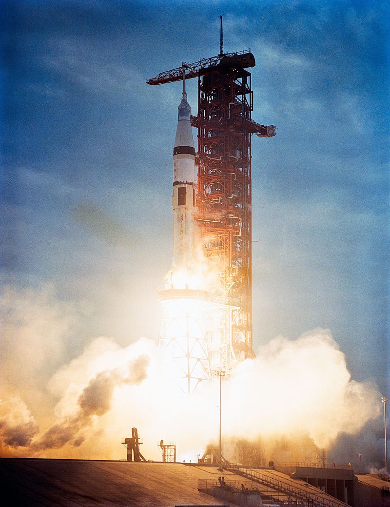
Skylab 3 Launch (Wiki)
U.S. Manned Rocket Propulsion Evolution
Part 7: Jupiter, Saturn I and Saturn IB
Compiled by Kimble D. McCutcheon
Published 1 Mar 2021; Revised 8 Jan 2026
Skylab 3 Launch (Wiki) |
The Saturn I launch vehicle series consisted of a 1.5M lbT-class stage 1 booster with several planned upper-stage configurations adaptable to specific missions. It was an extension of technology developed for the SM-78/PGM-19A Jupiter intermediate range ballistic missile. Although the Saturn I started as a military design, the Von Braun team always had manned space flight in mind as the launch vehicle took shape. The first-generation (Block I) Saturn I booster, called S-I, was a finless design that anticipated the use of Pratt & Whitney RL10- powered upper stages. The second-generation (Block II) S-IB, with six or eight fixed aerodynamic fins and uprated Rocketdyne H-1 engines also used several different upper stage configurations, the manned versions of which were called the S-IVB and were based around the new Rocketdyne J-2 LH2/LOX engine. The S-IVB stage will be discussed in a future article on the Saturn V. Since much Saturn I and IB technology was based on Redstone and Jupiter missile technology, we shall take a brief detour into the world of Jupiter. |
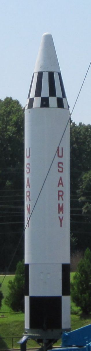 Jupiter Missile at USSRC |
Jupiter
The Jupiter Intermediate Range Ballistic Missile (IRBM) was originally developed by the U.S. Army as a long-range successor to its PGM-11 Redstone missile, but was eventually taken over and deployed by the USAF for political reasons. It was also the only one of the United States' early strategic ballistic missiles with some mobility.
Shortly after Von Braun and his ABMA team got the Redstone missile into production, they started looking into more powerful launch vehicles able to carry larger warheads over longer distances. Thus began the SM-78/PGM-19A Jupiter program in 1954 as an intermediate range ballistic missile (IRBM) with a 1,000 mile range. Shortly thereafter, the Air Force started a similar development, the SM-75/PGM-17 Thor IRBM. The Department of Defense ordered the ABMA to work with the U.S. Navy and develop Jupiter a sea-launched missile. This accounted for Jupiter's squat, finless appearance; it was to be launched from submarine launch tubes. It soon became apparent that a liquid-fueled missile presented an insurmountable shipboard safety problem, so on 1 Nov 1956, the Navy dropped the Jupiter in favor of the solid-fueled Polaris missile.
On 26 Nov 1956, just as Jupiter was nearing its first flight, Secretary of Defense Charles E. Wilson ended the argument between the Air Force and Army surface-to-surface ballistic missile responsibility by ruling that the Air Force would have responsibility for all ICBMs and IRBMs with ranges greater than 200 miles. This decision was later changed when the U.S.S.R started developing more capable missiles. But for a time, Jupiter was an Air Force project.
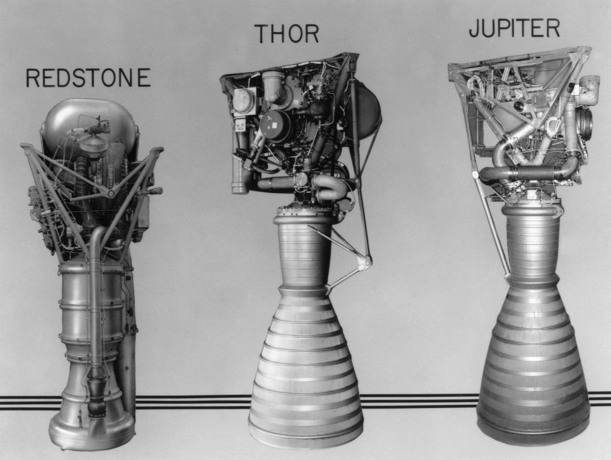
Both Jupiter and Thor IRBM were single-stage missiles that used essentially the same 135,000 lbT LR79/S-3D rocket engine, which burned RP-1 and LOX. The single thrust chamber was gimbaled for pitch and yaw control and used a swiveling turbopump exhaust nozzle for roll control. The first Jupiter R&D missile was launched on 1 Mar 1957, but it only flew for about eight seconds before exploding; the missile tail had overheated and failed structurally. Further tests had problems with fuel sloshing and turbopump explosions. The first completely successful flight occurred on 31 May 1957.
Jupiter launch sites were mobile, which gave them an advantage over Thor's more vulnerable launch sites, which were permanent. Jupiter's ablative reentry vehicle was much faster than Thor's, which when coupled with the Ford Instrument ST-90 guidance system, made Jupiter much more accurate. Between 1958 and 1961, Jupiter missiles were deployed in the United States, Italy and Turkey. However the U.S. Navy's deployment Polaris Submarine-Launched Ballistic Missiles had made land-based IRBMs redundant; all Jupiters were retired by July 1963.
Jupiter was 60.0 feet tall, 8.75 feet in diameter and weighed 110,000 lb fully fueled. [http://www.astronautix.com/j/jupiter.html, http://www.designation-systems.net/dusrm/m-19.html]
 |
 |
 |
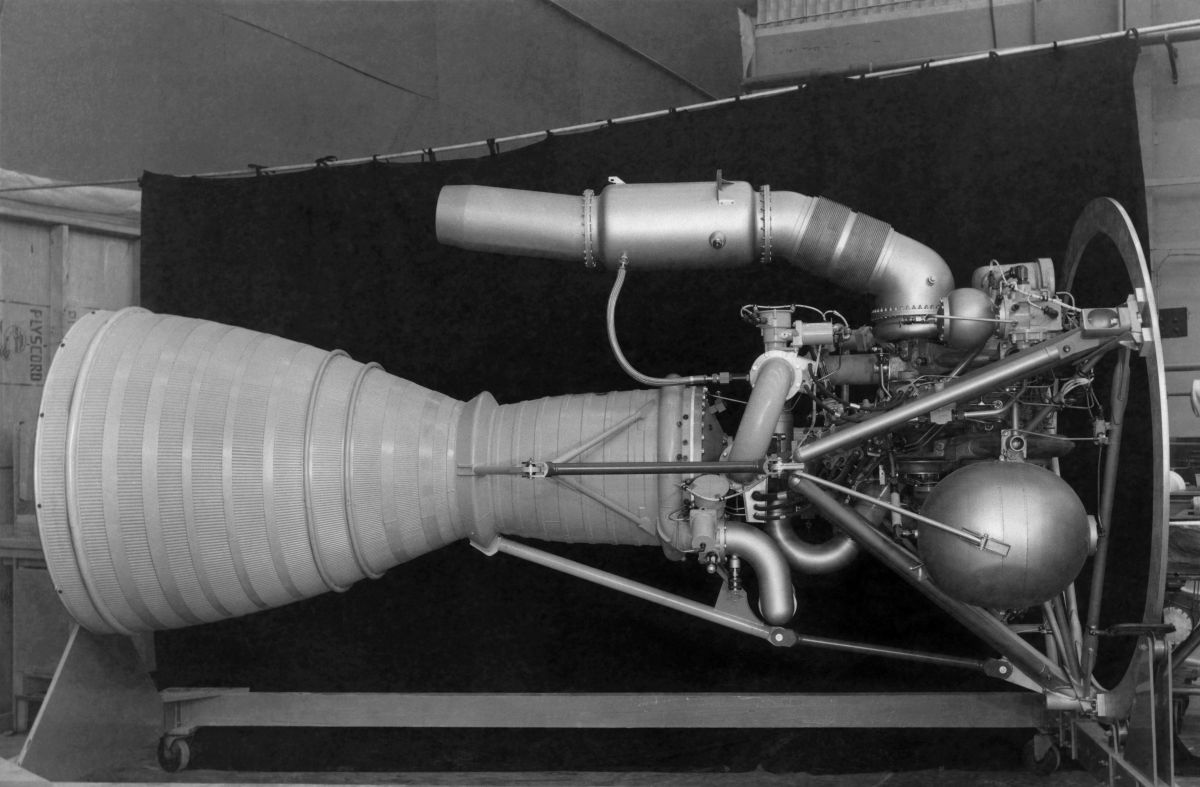
| Rocketdyne Engine Evolution (heriocrelics.org) | Jupiter S-3D Engine (heriocrelics.org) | S-3D Engine Details (heriocrelics.org) |
 Saturn I and IB Series (historicspacecraft.com) |
Saturn I
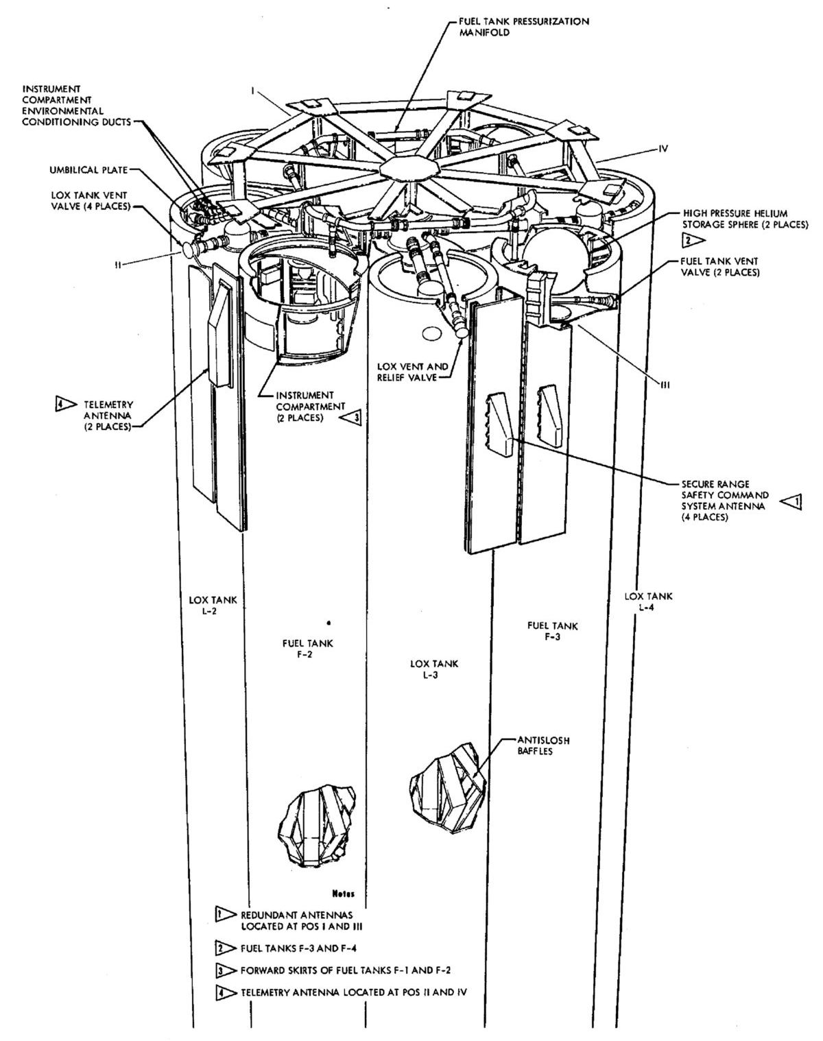
The Saturn I concept emerged in two ABMA reports to the Advanced Research Products Agency in October and November 1958. Eight engines derived from the Jupiter's Rocketdyne S-3D engine were clustered on a tail unit in two rings so that engines in the inner ring were fixed and engines in the outer ring were gimbaled. Above the tail unit was a nine-tank cluster. A central LOX tank with the same 105" diameter as the Jupiter missile, had eight 70" diameter tanks (same as Redstone) clustered around it; four were painted black and held RP-1 and the remaining alternating four were painted white and held LOX. Some wags derisively named this configuration "Cluster's Last Stand." Although the Saturn I began as a military booster, it and the people who created it were ultimately transferred to the National Aeronautics and Space Administration (NASA). ABMA personnel and facilities became part of the NASA George C. Marshall Space Flight Center (MSFC) on 1 Jul 1960.
The clustered multi-tank scheme allowed MSFC and Chrysler to rapidly construct the Saturn I using tooling it already had in place for Redstone and Jupiter production. Although the Saturn I tanks were 145" longer, diameter was the main tooling consideration. The multi-tank approach avoided the bulkhead and slosh baffle engineering that would have been required for single large tanks, and allowed the tank components to be transported in Douglas C-124 cargo aircraft. [Bilstein, 76]]
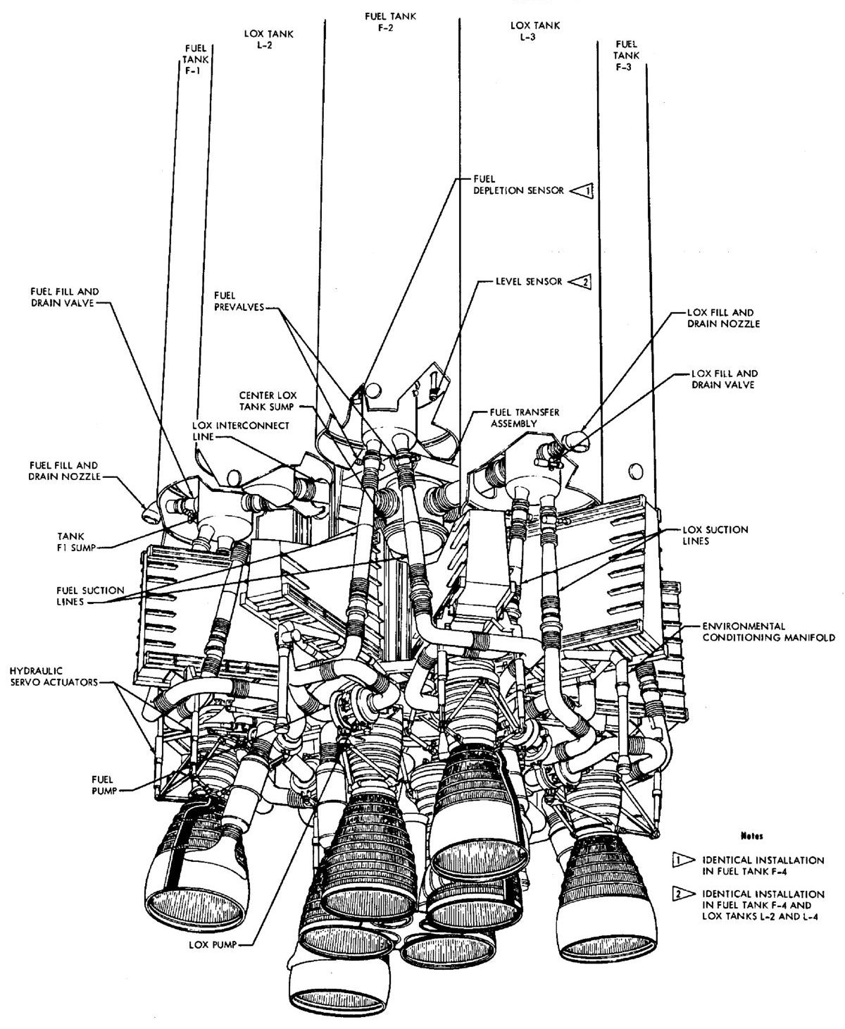
A major S-I development obstacle was base heating, which occurred when the rocket exhaust encountered shock waves trailing the vehicle, creating unpredictable regions of dead air and zones of turbulent mixing. The trapped air was heated to unacceptable temperatures and fuel-rich turbopump exhaust streams could interact with the dead air and hot spots and combust. ABMA engineers arranged the engines in a cross shape and placed the inner engines as close together as possible; this minimized the stagnant and turbulent zones. The lower skirt was designed to direct high-velocity air across the vehicle base toward its center. A heavy firewall across the booster base at the nozzle throat level with flexible engine skirts to permit outer engine gimbaling prevented high-temperature gas from reaching the turbopumps and fuel lines above. The center-engine turbopump exhaust was routed to the inner cluster center and dumped into the high-velocity air at the vehicle center. The gimbaled outboard engine turbopump exhausts dumped into sheet-metal aspirators that routed it to the nozzle periphery where it mixed with the main exhaust stream.
Another S-I development challenge was stability and control. The great distance between the vehicles center of pressure and center of gravity, which changed as propellant was consumed and staging occurred. This required advances in guidance and control systems. One particularly thorny problem was that of compensating for propellant slosh and for vehicle vibration and bending modes. ABMA engineers used analog computers to simulate propellant sloshing and modified the control laws accordingly. Although the Saturn I is a huge vehicle, it is really very light for its size, which makes it very flexible and prone to vibrate at the same frequency as engine gimbaling in response to certain flight regimes. Engineers had to modify the control laws to compensate, making sure that an unfortunately-timed engine movement did not break the vehicle.
In a time when rocket engines did not always successfully ignite, many were skeptical that an eight-engine configuration was feasible. ABMA engineers built a huge test stand on Redstone Arsenal, Alabama and performed the first timid two-engine start in late March 1959. By mid-June all eight engines were running at full power for more than two minutes. [Bilstein, 78-80]
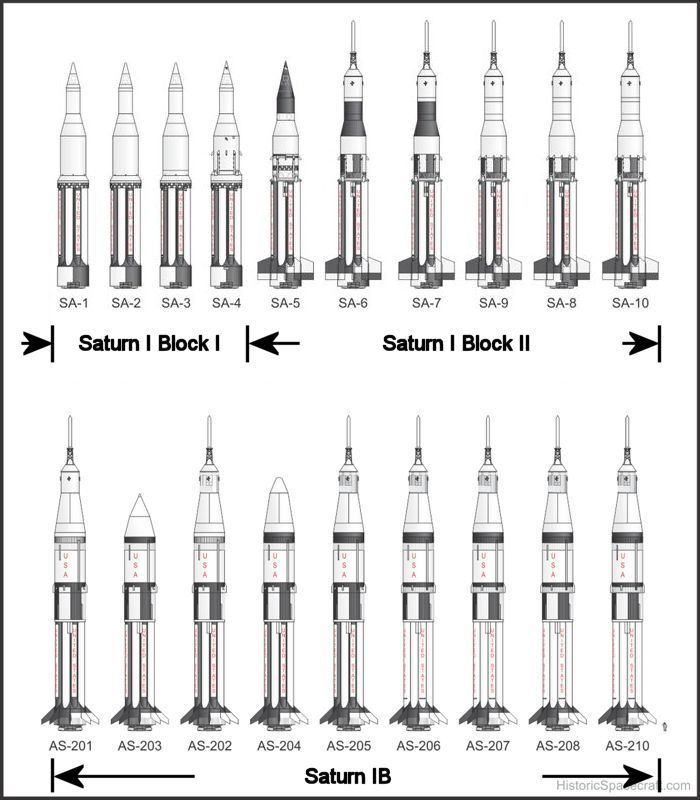
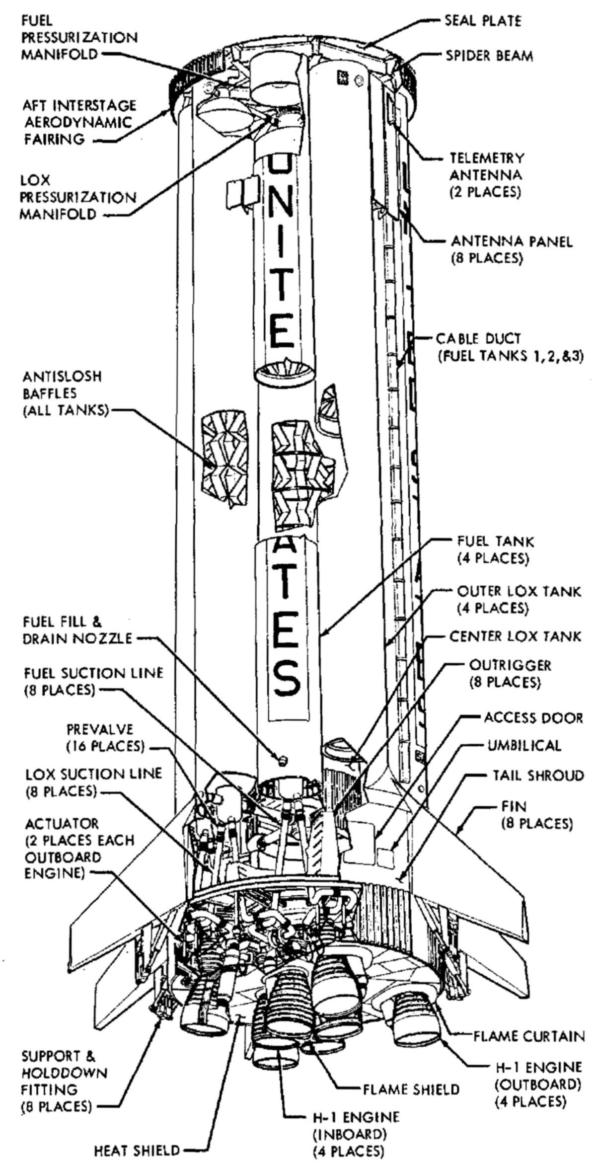
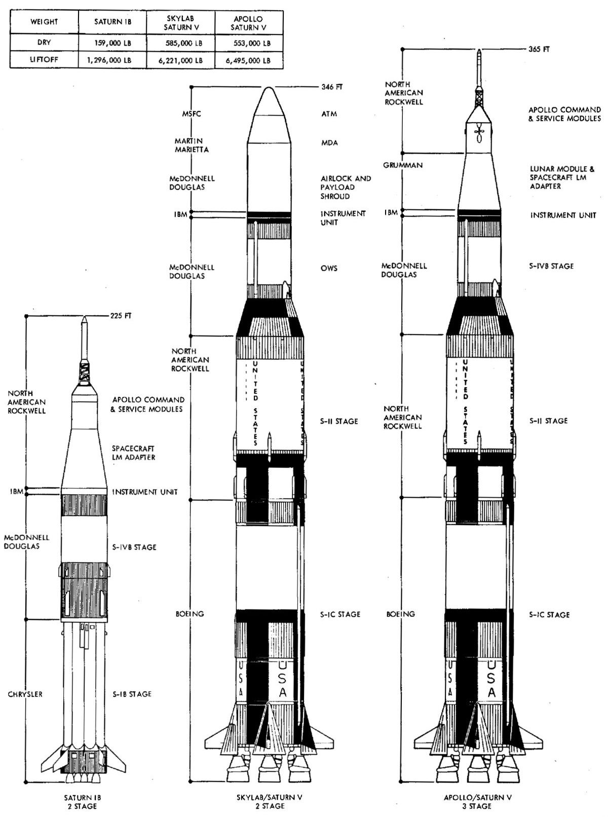
The Saturn I used an S-I first stage that was 80.31 feet high, 21.39 feet in diameter, had a loaded mass of 953,898 lb. Eight Rocketdyne H-1 engines burning RP-1 and LOX provided 1,704,524 lbT and was able to launch a 19,800 lb payload into low earth orbit. Ten Saturn I rockets were built and launched, the first on 27 Oct 1961. The first four, Serials S-101 through S-104, were Block I test articles with dummy upper stages. S-105 was the first Block II version, had six large aerodynamic fins, and a live S-IV second stage, which was built by Douglas and powered by six Pratt & Whitney RL10 LH2/LOX engines. The remaining S-106 through S-110, also with the Douglas second stage, launched boilerplate Apollo Command and Service Modules. The last three also launched Pegasus micrometeoroid detectors.
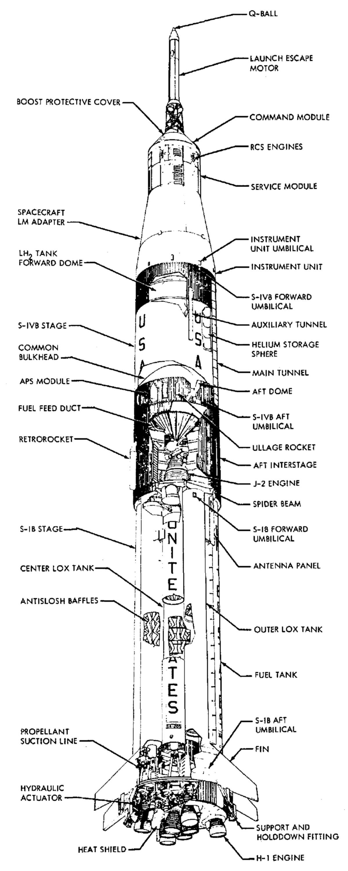
The Saturn IB used an uprated S-IB first stage that was 80.31 feet high, 21.39 feet in diameter, had a loaded mass of 989,099 lb. Eight Rocketdyne H-1b engines burning RP-1 and LOX provided 1,852,822 lbT and was able to launch a 41,000 lb payload into low earth orbit. The first stage featured eight aerodynamic fins with noticeably higher aspect ratio than those used on S-I.
The Saturn IB also made use of the new Douglas S-IVB second stage, powered by a single Rocketdyne LH2/LOX J-2 engine. This same stage was also used as a Saturn V third stage and will be discussed in detail in a future article. Twelve Saturn IBs were built, but only nine were launched; the remainder are in museums or displays. Saturn IB SA-201 first took flight on 26 Feb 1966. After two more test flights, the uncrewed Apollo 5 (SA-204) was launched on 22 Jan 1968 to test the Lunar Module in earth orbit. Apollo 7 (SA-205), the first crewed Apollo mission, was launched on 11 Oct 1968 and was so successful that NASA opted to launch the famous Apollo 8 Saturn V mission in late December 1968. Then next three missions, SA-206 through SA-208 were dedicated to the Skylab missions, and the final one, SA-209, docked with Soviet Soyuz 19 spacecraft. [https://historicspacecraft.com/Rockets_Saturn.html]
 |
 |
 |
 |
 |
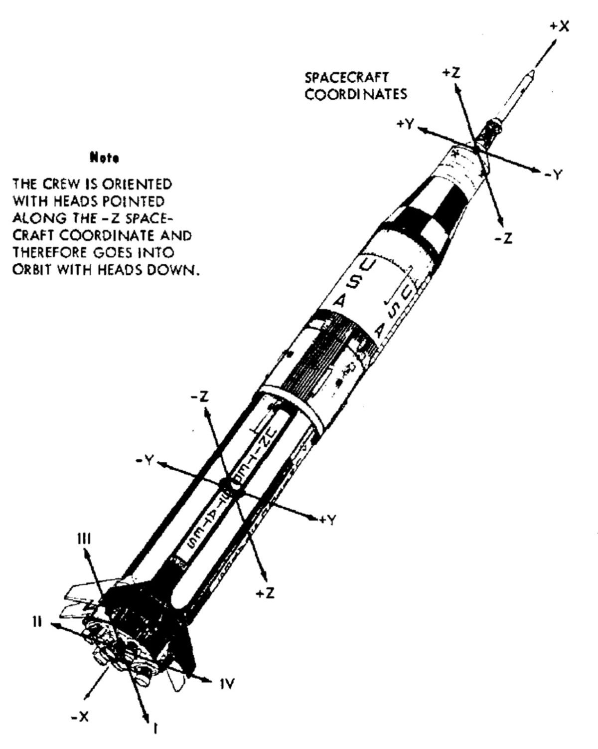
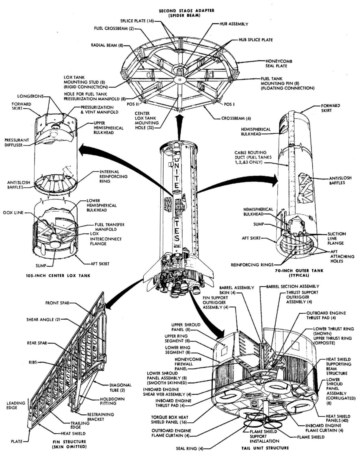
| Saturn IB Cutaway | Saturn Vehicle Coordinate System | Saturn IB Stage | Saturn IB Stage Forward Detail | Saturn IB Aft Detail |
 |
 |
 |
 |
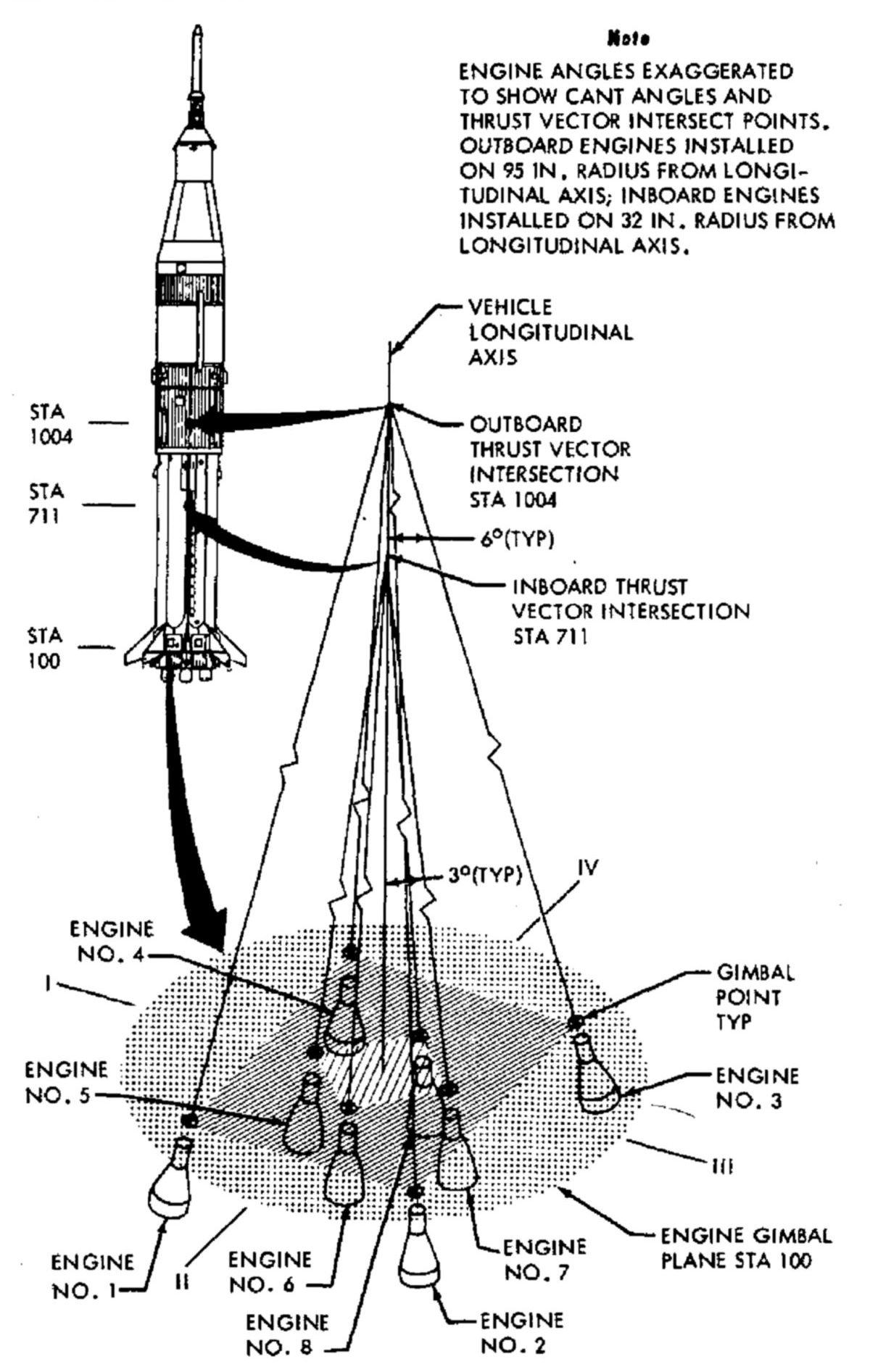 |
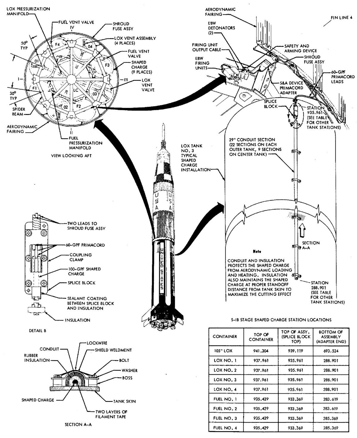
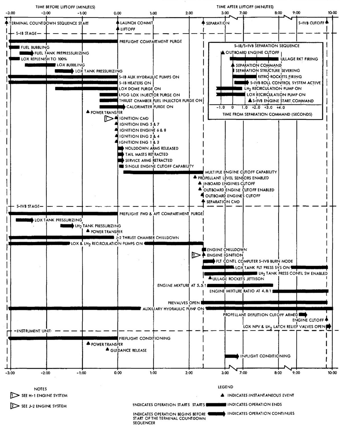
| Saturn IB Stage Structure | Saturn IB and Saturn V Configurations | Saturn IB Range Safety System | Saturn IB Flight Event Sequence | Saturn IB Thrust Vectors |
 |
 |
 |
 |
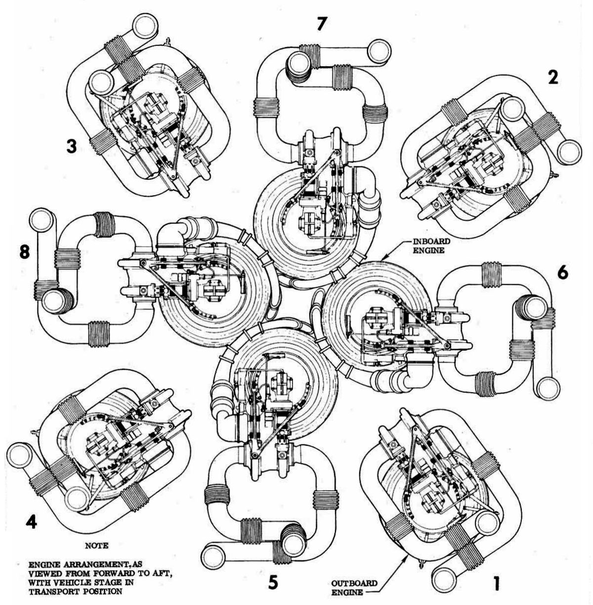 |
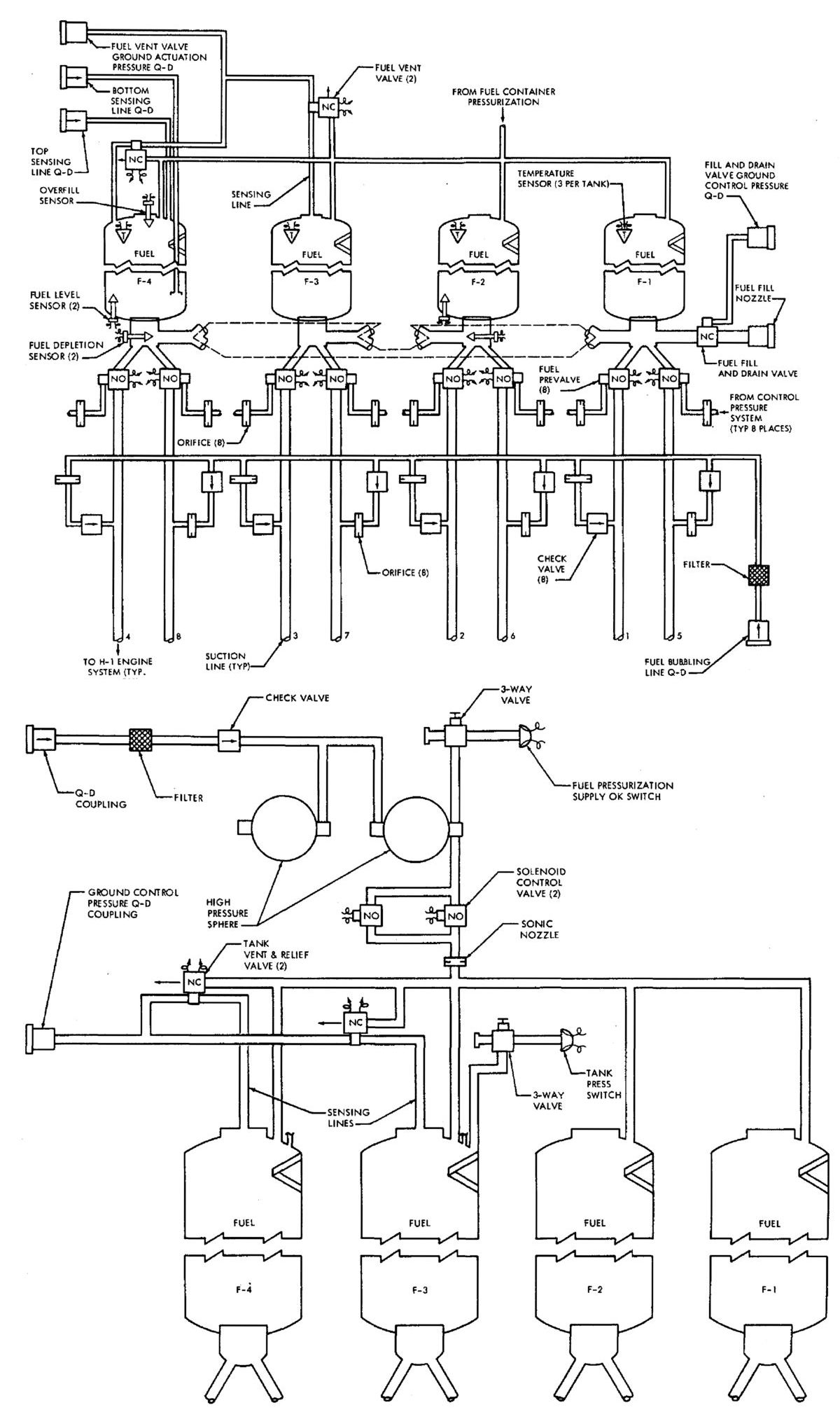
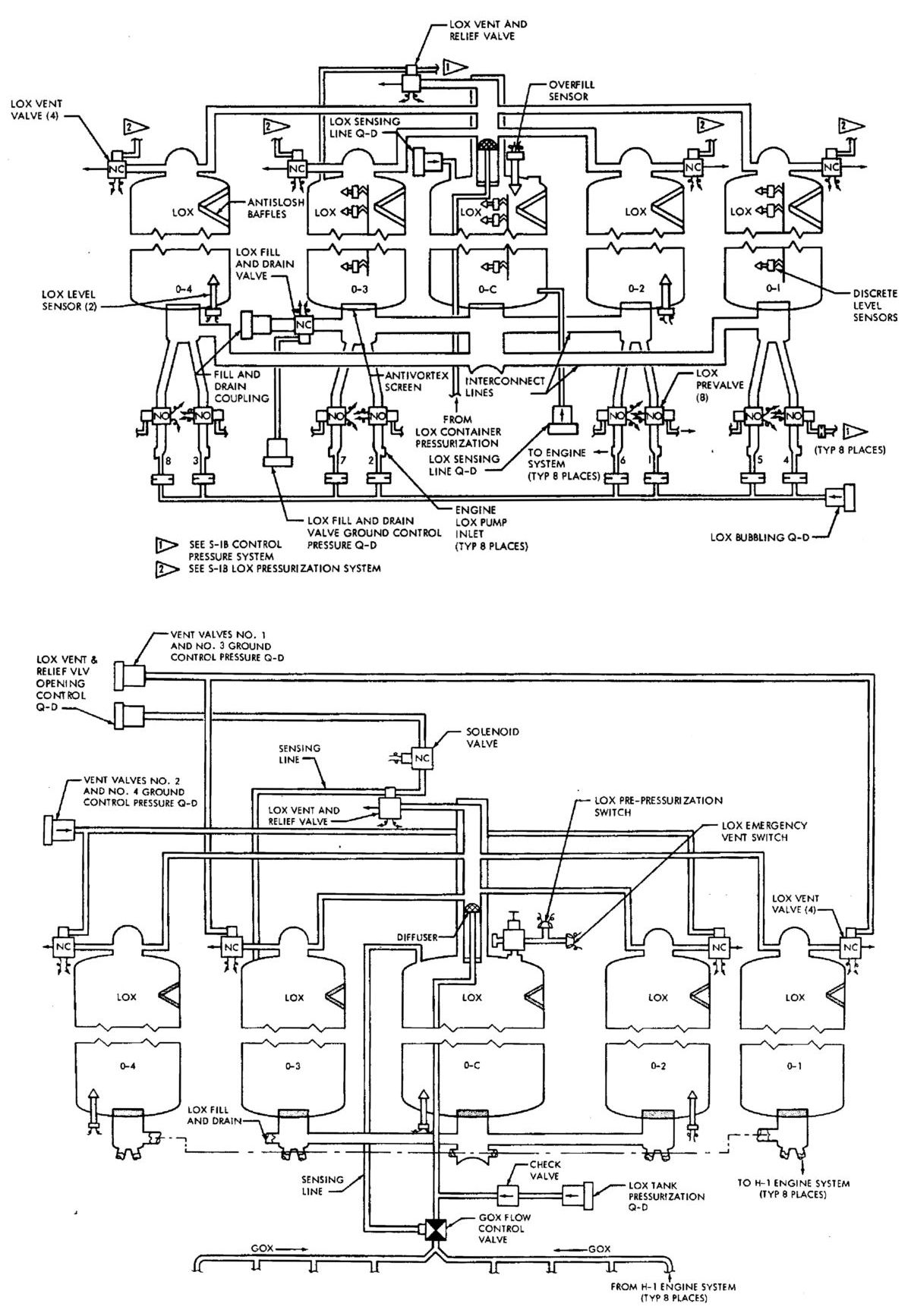
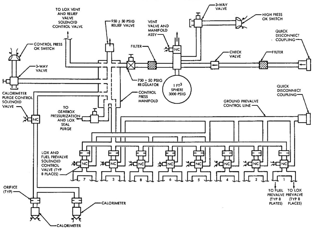
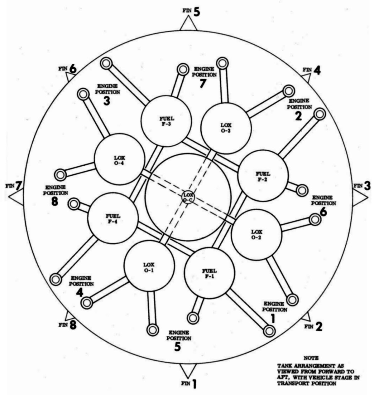
| Saturn IB Fuel System Details | Saturn IB LOX System Detail | Saturn IB Pressure System | Propellant Tanks and Ducts | Engine Cluster |
The H-1 Engine
Development
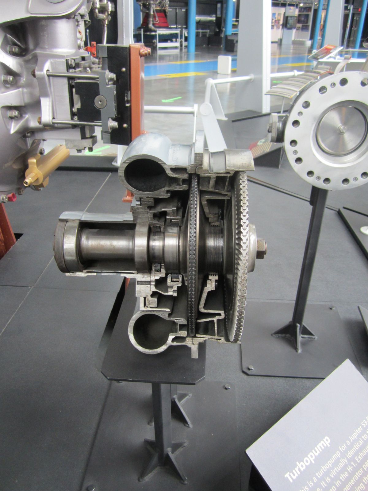
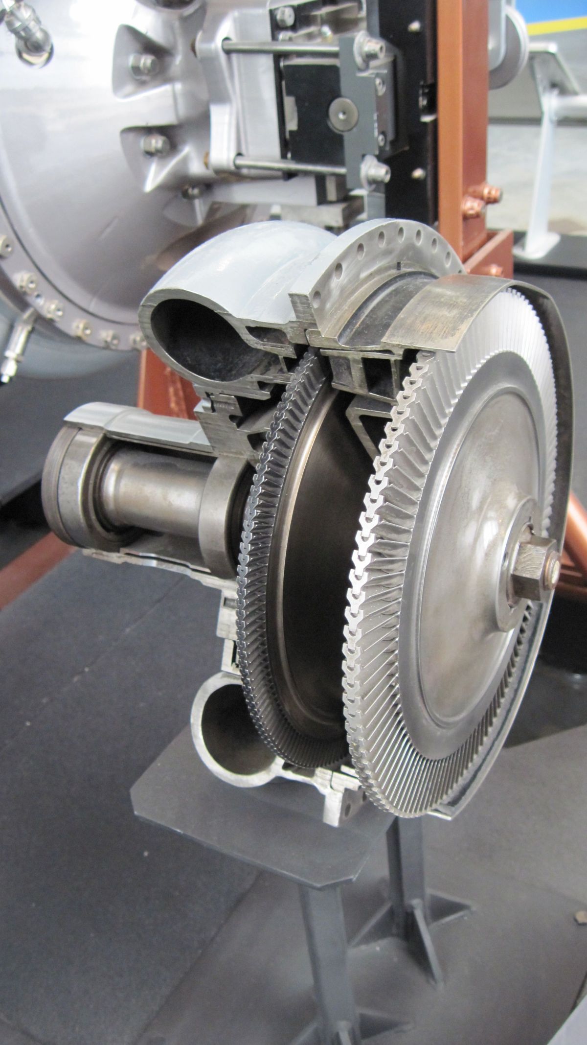
Turbopumps
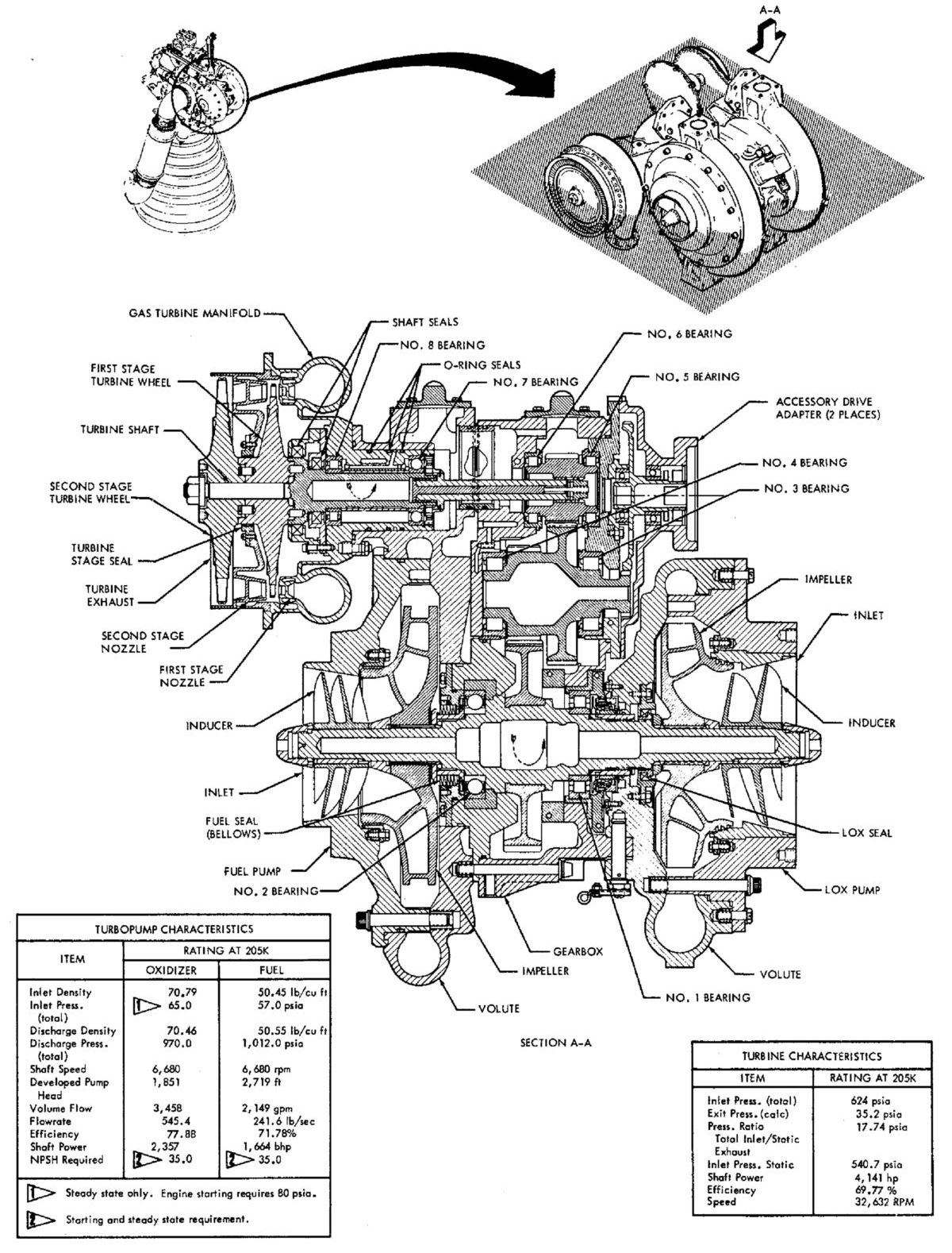
Advances in one area of propulsion systems created demands on other components. As thrust and pressures increased, so did demands on the turbomachinery to supply propellants at greater flow rates and higher pressures. Thus, higher-powered turbomachinery without increases in size or weight had to be developed. Advances in turbomachinery design centered on higher speeds, and the goal of higher speeds encouraged the introduction of rotating components with smaller diameters. Essential subsidiary improvements dealt with high-speed bearings, inducers, and impeller tips. Engineers succeeded in increasing bearings operating speed through minute attention to operating environment details and the fabrication of bearing parts. Designers reconsidered and redesigned bearings to optimize their size, surface contact angle, and race structure curvature. Better performance was gained by engineering the newly designed bearings for combating contact fatigue and wear from overheating. Further refinements included the introduction of new, high-strength materials and improved surface finishes in the fabrication of precision parts. The innovative use of the engine's own propellants as "lubricants" was another advance. Although the propellants were not lubricants in the usual sense, they served the same purpose. Propellant-lubricants were more important in carrying off frictional heat to keep pump bearings cool and operable. This application simplified turbopump operation and eliminated the need for externally supplied lubrication.
Engine designers also attacked propellant cavitation, a condition in which the formation and collapse of bubbles or vapor pockets while pumping the propellant caused vibrations and damage to rocket machinery. Study programs found how the cavitation characteristics were related to the inducer through such minute factors as blade angle, taper, blade sweep, and leading edge profile. More accurate cavitation phenomenon theories enabled a redesign of the inducers that doubled their suction. The overall increase in turbopump suction efficiency permitted the pump to operate at higher speeds, which contributed to vehicle weight savings because tank pressures and tank weight could be lowered. The higher operating speeds and pressures triggered development of pump impellers that operated with higher tip speeds. The infusion of high-strength materials, plus design improvements and fabrication techniques paid off in reliability and greater speed. In total, all of these developments enhanced the incremental power-to-weight ratio gains.
 |
 |
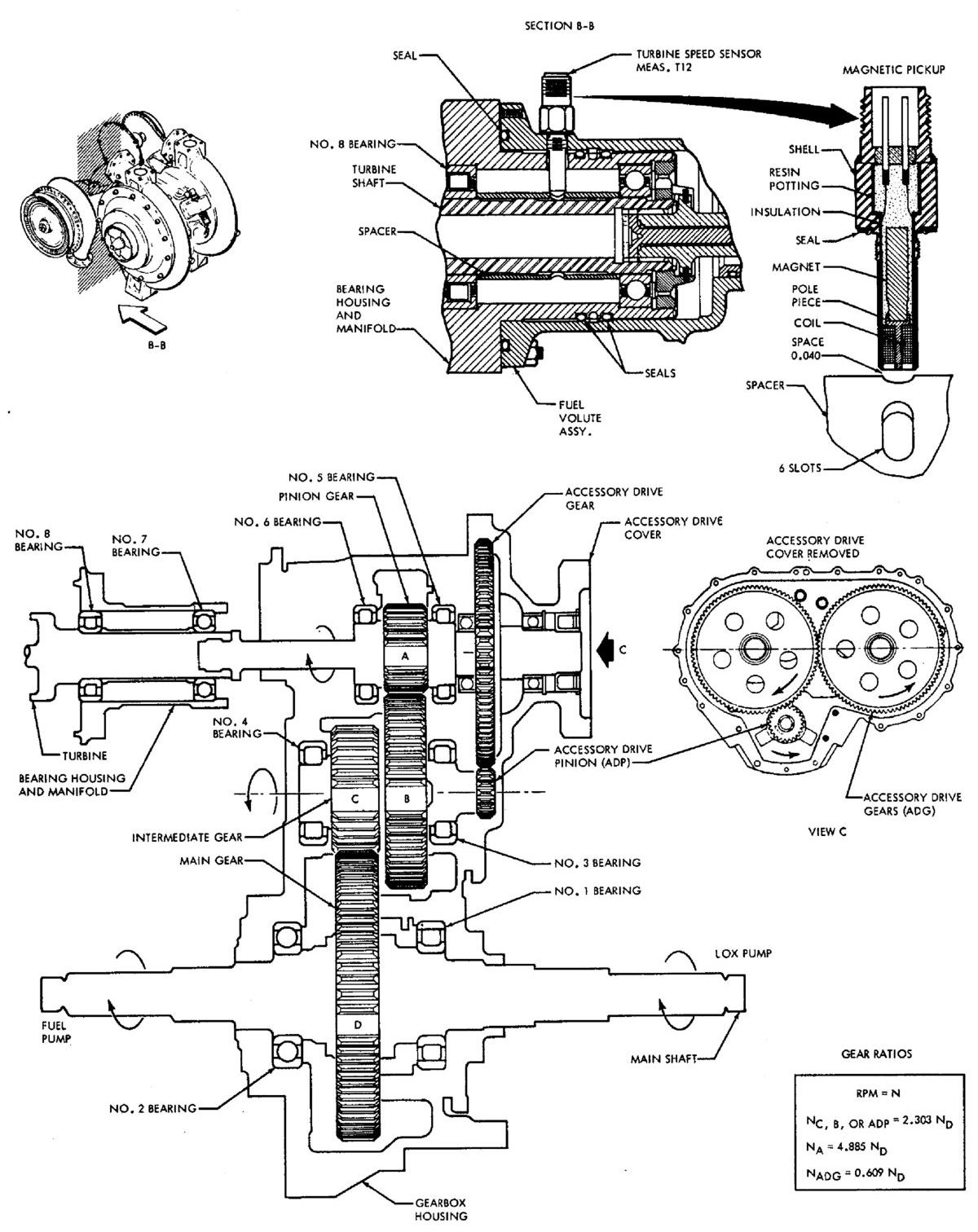 |
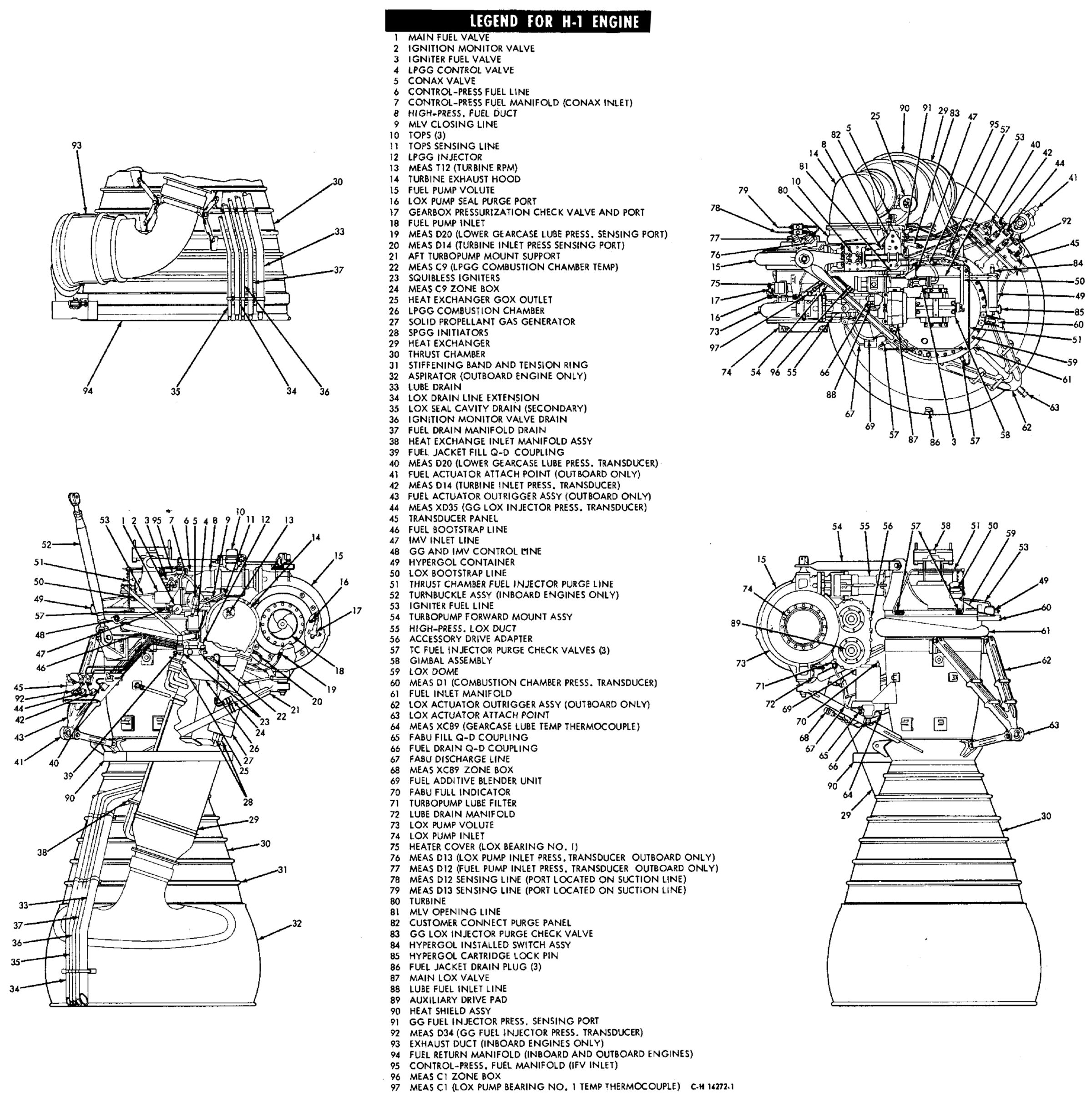
| H-1 Engine External Detail | H-1 Turbopump Detail | H-1 Turbopump Detail |
Packaging and System Design
Cryogenic rocket engine packaging and design made dramatic progress over a brief span of time. Thrust chamber size increased, while pumps, turbomachinery, and related systems remained relatively constant or actually decreased in physical size. At the same time, efficiency and design advantages accrued. In the early Redstone days, builders situated the turbopump, propellant lines, and controls above the thrust chamber and achieved directional control by using jet vanes. When gimbaled thrust chambers first appeared, pumps, lines, and other paraphernalia were attached to the vehicle's thrust structure. However, this created a problem; with the thrust chamber as the only movable part, engineers had to develop a new, very flexible, high-pressure feed lines to link the propellant pumps to the thrust chamber. As chamber pressures and thrust levels rose, increased strains on the high-pressure lines caused designers to study packaging that mounting the turbopump and associated gear onto the thrust chamber itself. In this configuration, the pump and chamber could be gimbaled as a single unit, permitting the installation of low-pressure "flex lines" between the pump inlets and the vehicle tanks. As it so happened, improvements in the design and efficiency of turbomachinery already made it compact and reliable enough to justify relocation on the thrust chamber.
Predictable Engine Problem Phases
H-1 Milestones and Facilities
In order to save time and money, NASA decided to modify the 150,000 lbT Thor/Jupiter S-3D to produce an uprated 188,000 lbT H-1. This was to be accomplished in stages, starting with a preliminary 165,000 lbT and eventually achieving 205,000 lbT. Development proceeded rapidly and the H-1 passed its Preliminary Flight Rating Test in the fall of 1960.
H-1 single-engine and component testing took place at Rocketdyne's Conoga Park facility and in the Santa Susana mountains, both in California. MSFC did component, single-engine and clustered-engine tests.
Engine Descripton
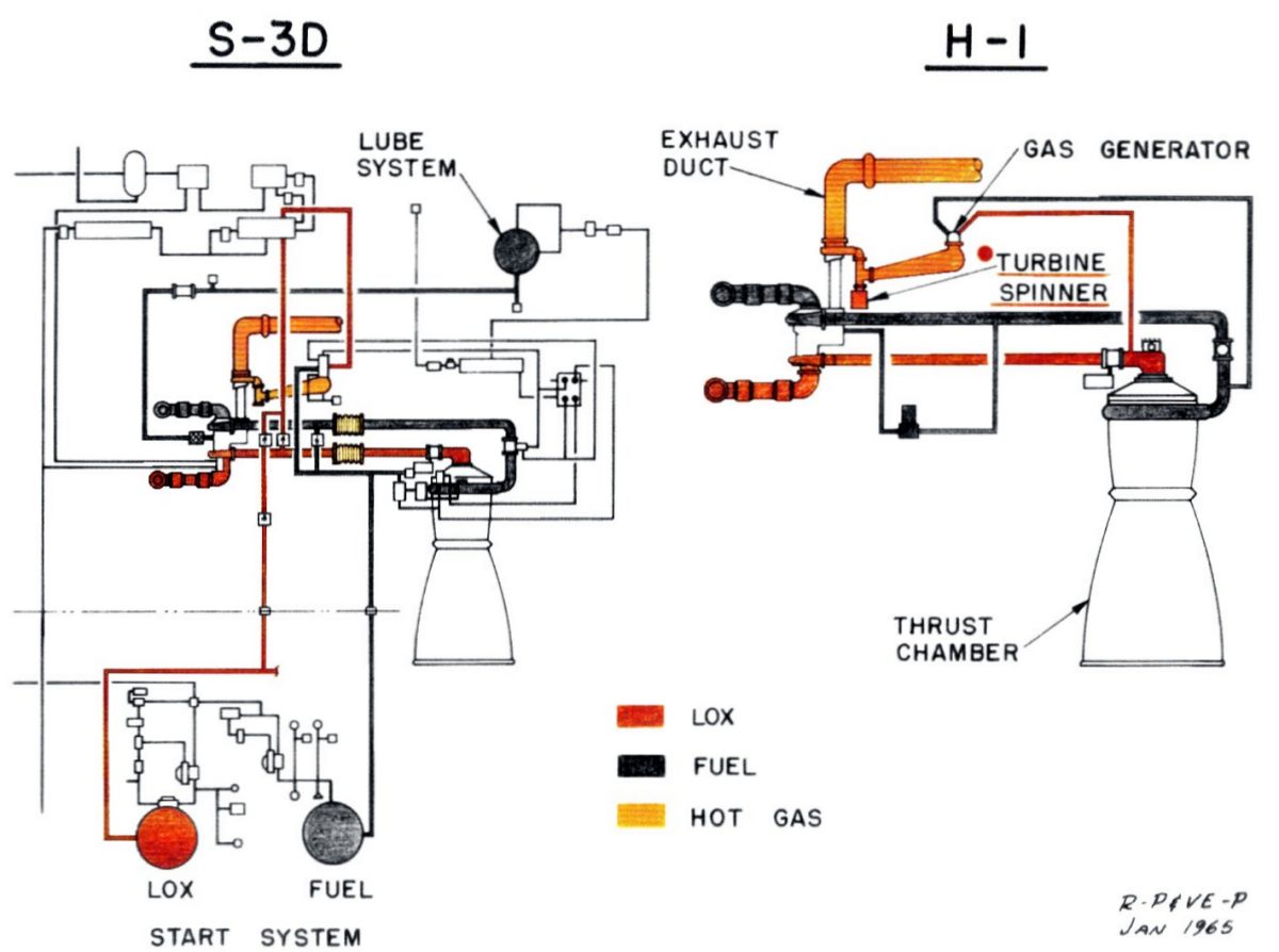 S-3D Simplification (heriocrelics.org) |
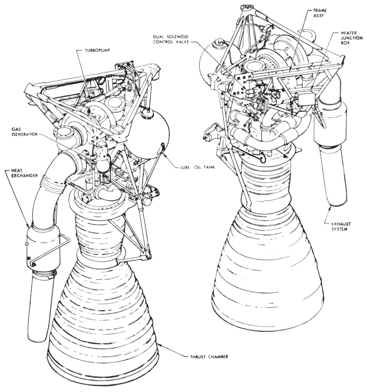
Production H-1s left Rocketdyne in two slightly different models. Each had a gimbal assembly for attachment to the vehicle, but the H-1C inboard engines, which did not participate in thrust vector control, were immobilized by struts that held them rigidly in place. The H-1D outboard engines were equipped with gimbal actuators, attached to outriggers on the thrust chamber, that produced the gimbaling action for vehicle directional control. The turbopump exhaust systems differed as well. H-1Cs had turbine exhaust ducts and heat exchangers that were routed through the vehicle center and exhausted at the vehicle center. The outboard H-1Ds routed turbopump exhaust into a Hastelloy C aspirator shell that exhausted just beyond the nozzle exit plane.
One of the most striking H-1 characteristic was its simplification compared to the S-3D. Gone was the 20-gal oil system, replaced with RP-1 with an additive blender unit. The start system was also simplified, relying on an integral system rather than the elaborate ground support.
Development Problems
Like most large engines, the H-1 had bouts of combustion instability, but no one could either predict the onset of the problem or guarantee that once it started it would damp out and avoid destroying the engine. NASA and Rocketdyne engineers came up with a clever way to test – they deliberately exploded a 50-grain bomb within the thrust chamber. This bomb consisted of a cylindrical nylon case that was attached to the injector. Once the engine came up to power, the bomb became hot enough to explode. This disturbed the flame front and caused instability in 8 of 16 tests. Eventually the combination of baffles on the injector face and some tweaking of the injector orifices solved the problem, damping the deliberately-induced instability in less than 0.1 second.
When vehicle SA-7 was undergoing a leak check series at the Kennedy Space Center in the fall of 1964, technicians came across a crack in an H-1 LOX dome. Investigation revealed the root cause was stress corrosion in the aluminum alloy that comprised the dome. Rocketdyne was fortunately working on a new aluminum alloy and new processing techniques that provided high stress corrosion resistance. The eight LOX domes were replaced and subsequent engines featured the new dome alloy.
When Rocketdyne uprated the H-1 from 165,000 lbT to 188,000 lbT, engineers started to notice longitudinal splits in the thrust chamber tubes. This was caused when sulphur in the RP-1 fuel precipitated out to combine with the thrust chamber tubes nickel alloy, resulting in sulphur embrittlement and failure. Rocketdyne changed the thrust chamber tube material from nickel alloy to stainless steel (347 alloy), which did not react with sulphur.
There were other problems, such at bits of Teflon and steel filings that had been discovered in engines. There was a case of the wrong material being used to manufacture turbopump blades. Enhanced attention to cleanliness and procedures prevented problems like these from recurring.
With this kind of quality control and inspection, the H-1 engines experienced only one serious problem in 15 launches of the Saturn I and Saturn lB. During the flight of SA-6 in May 1964, one engine shut down prematurely. The vehicle's "engine-out" design proved its worth, as the mission continued to a successful conclusion. Based on information transmitted during the flight, analysts located the failure in the power train, "somewhere between the turbine shaft and the C-pinion in the turbopump." The incident was not entirely unexpected. prior to the flight, a product improvement team had already developed an improved power train design. In fact, starting with vehicle SA-7, the new units had already been installed. [Bilstein, 93 – 104]
Operation
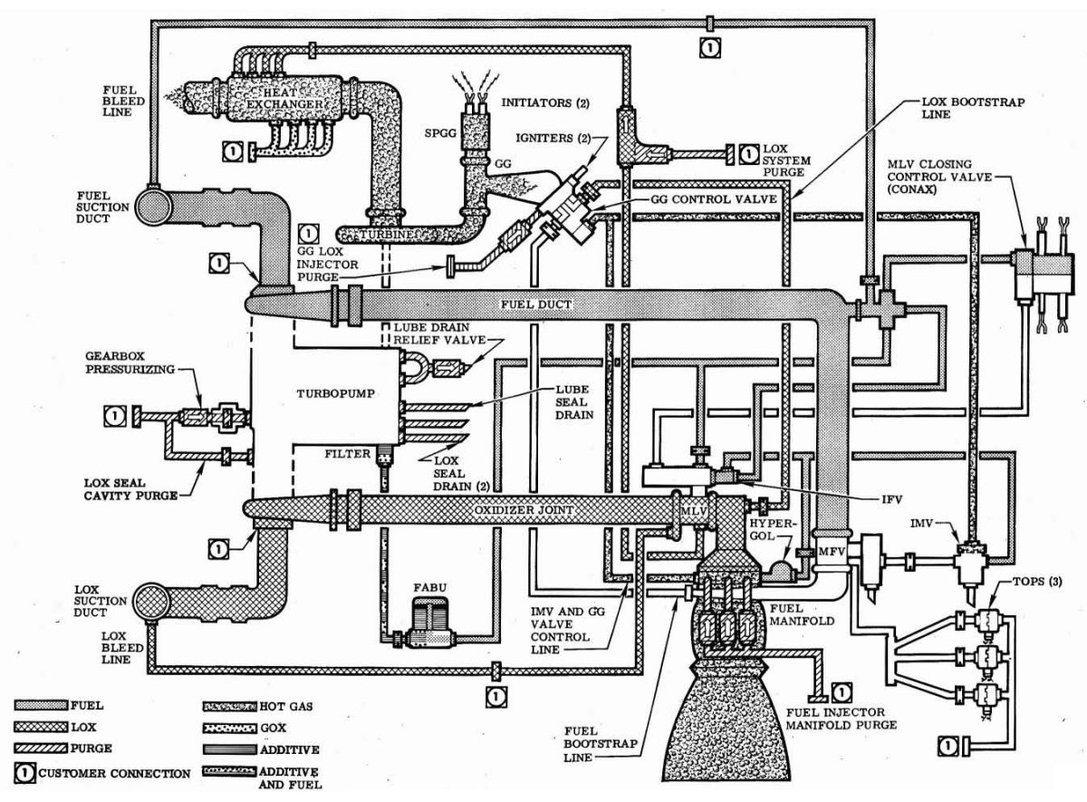
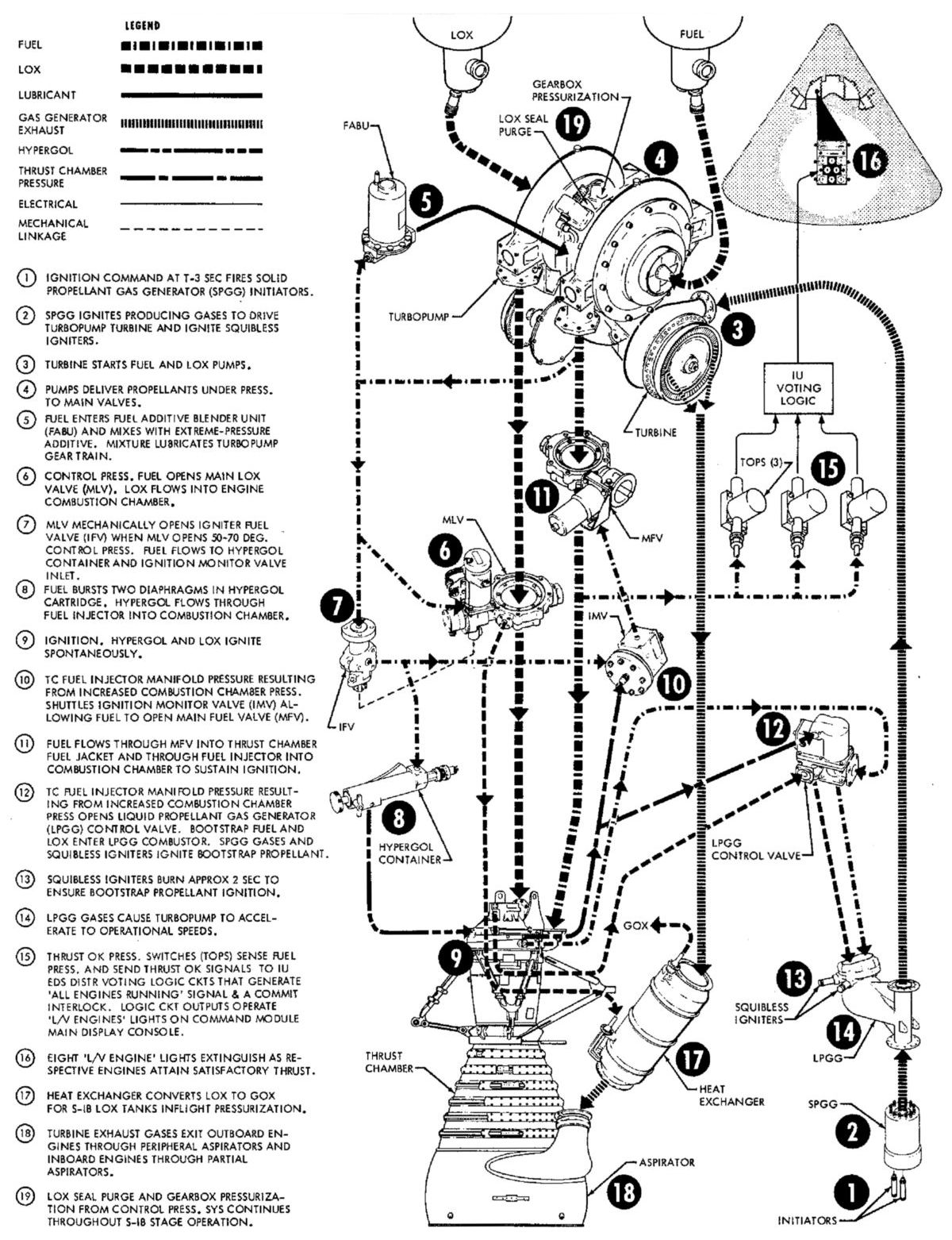
To prepare the engine for firing, the fuel additive blender unit was serviced with additive, the thrust chamber jacket prefilled with fuel, and the main LOX valve closing control valve, solid propellant gas generator, gas generator igniters, hypergol cartridge, and solid propellant gas generator initiators installed. The LOX pump seal cavity, gearbox pressurization purge and LOX system by-pass purge, were initiated. Propellants then dropped to load the turbopump LOX and fuel pump sections and fill the engine high-pressure ducts up to the closed main LOX valve and main fuel valve. Fuel was routed through the series control lines to the main LOX valve closing control valve, fuel additive blender unit, igniter fuel valve, and opening control port on the main LOX valve. Activating purges for the LOX system, gas generator LOX injector, and thrust chamber fuel injector completed engine prefiring preparations.
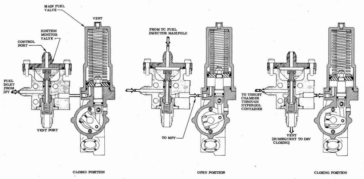
When the engine firing switch was actuated, an electrical signal to the solid propellant gas generator (SPGG) initiators ignited the solid propellant charge, which produced hot gases that accelerated the turbine, pressurizing the turbopump monitor valve control port. Sufficient pressure at the control port opened the ignition monitor valve, which allowed fuel control pressure to open the main fuel valve. Fuel under turbopump pressure flowed through the open main fuel valve, to the fuel bootstrap line, through the thrust chamber fuel jacket, through the injector, and into the thrust chamber combustion zone where main propellant ignition was accomplished. Increasing fuel pressure resulting from main propellant ignition and sensed at the thrust chamber fuel injector manifold, opened the liquid propellant gas generator control valve. Bootstrap propellants entered the liquid propellant gas generator, with a slight LOX lead, and were ignited by hot gases from the solid propellant gas generator and the two gas generator igniters. The turbopump accelerated, thrust built up, and rated operation was attained.
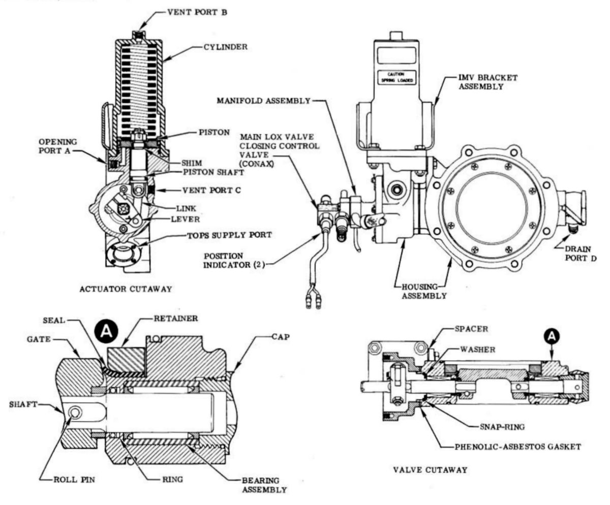
Engine shutdown was achieved by an electrical cutoff signal that fired a pyrotechnic-actuated main LOX valve closing control valve.Opening of this valve allowed fuel pump discharge pressure to enter the closing port of the main LOX valve actuator, equalizing the fuel pressure on both sides of the valve actuation piston. The main LOX valve then closed by the fuel pressure, acting on the larger piston surface area on the closing side, which, in conjunction with spring force, cut off LOX flow to the thrust chamber and gas generator, resulting in turbopump speed and propellant pressure decay. Closing the main LOX valve allowed the igniter fuel valve to close, shutting off fuel pressure to the hypergol container inlet, ignition monitor valve inlet, and main fuel valve opening port. When the main fuel valve actuation pressure decayed to approximately 200 psig, the main fuel valve closed under spring force, completing engine shutdown approximately one second after cutoff signal. A fuel-rich shutdown was provided to prevent a temperature spike in the liquid propellant gas generator. A natural, fuel-rich shutdown occurred in the thrust chamber.
 |
 |
 |
| H-1 Ignition Schematic | Main Fuel Valve | Ignition Monitor Valve and Main Fuel Valve Operation |
 |
 |
 |
| Main LOX Valve | Main LOX Valve Actuation | Hypergol Container with Cartridge Installed |
 |
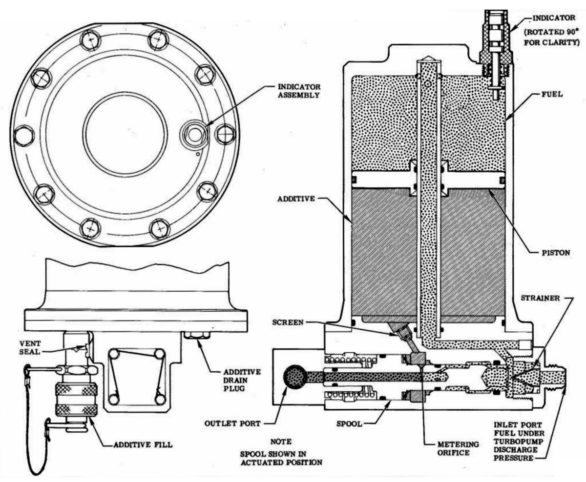 |
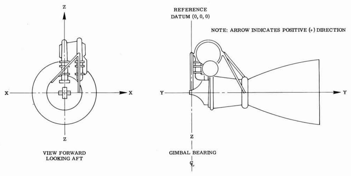 |
| Gas Generator Igniter | Fuel Additive Blender Unit (FABU) | Engine Axes |
 |
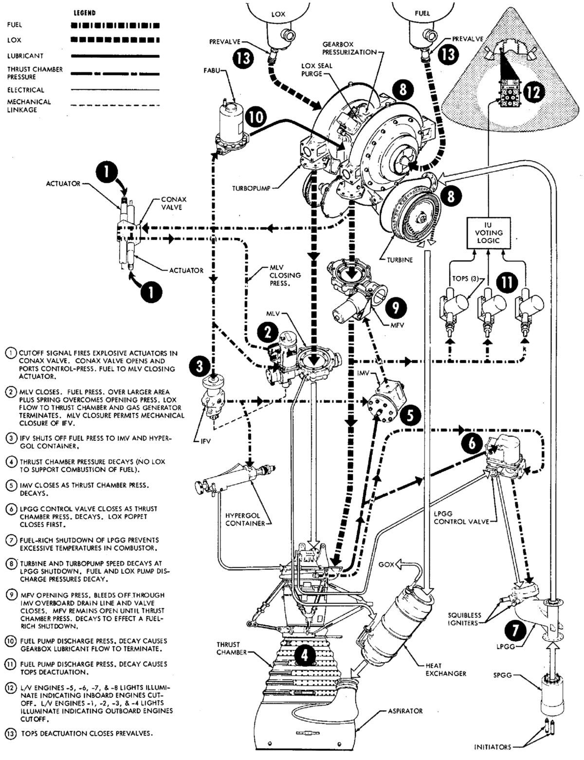 |
| Start and Run | Cutoff |
 |
 |
 |
 |
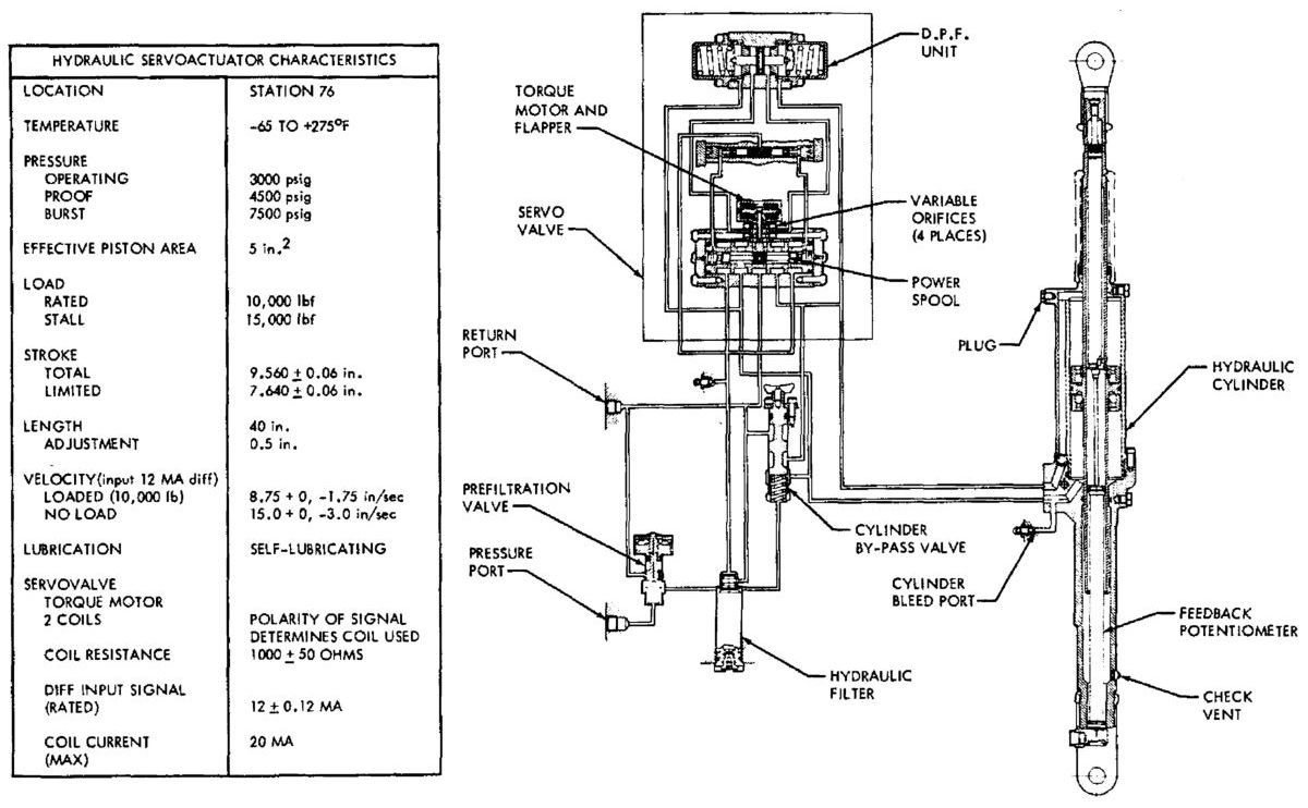 |
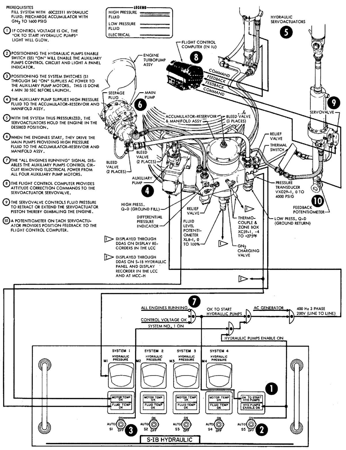
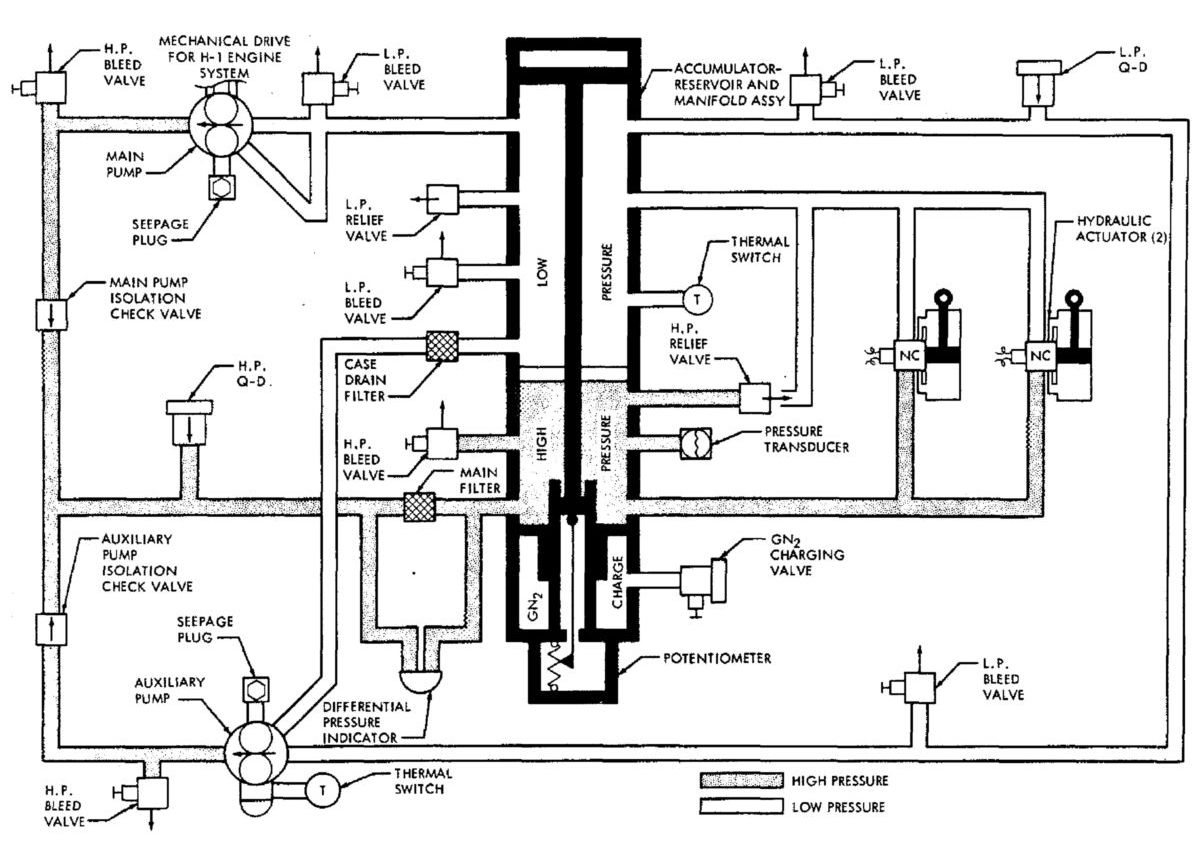
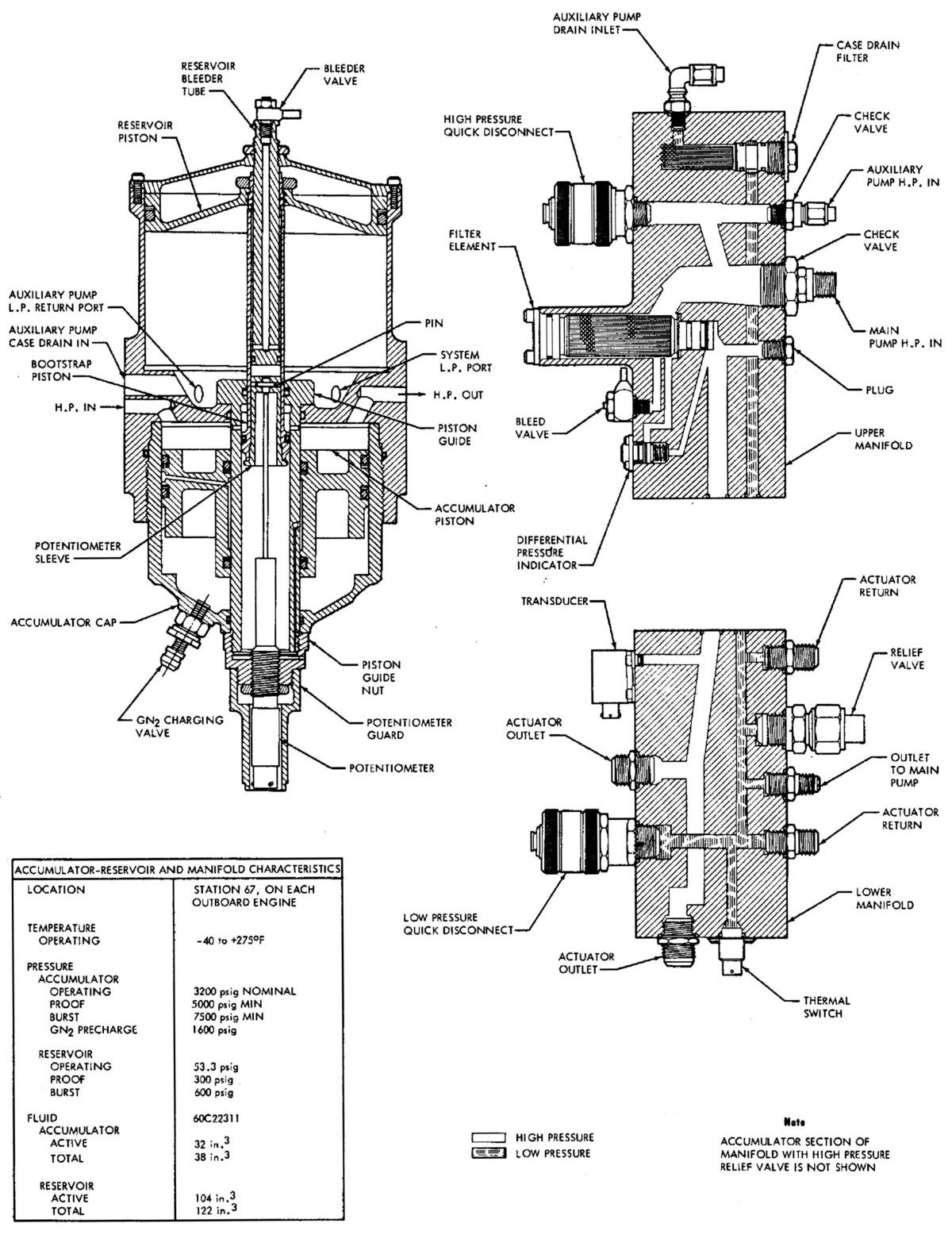
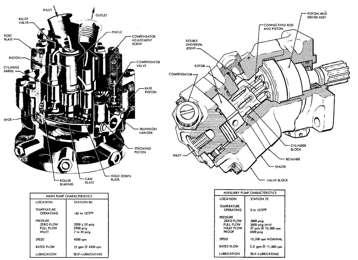
| External Components | Operational Schematic | Accumulator and Manifold | Pumps | Servoactuator |
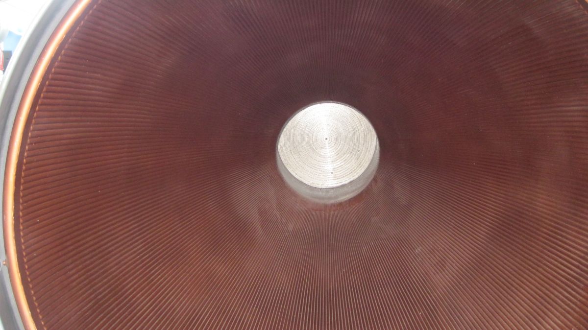
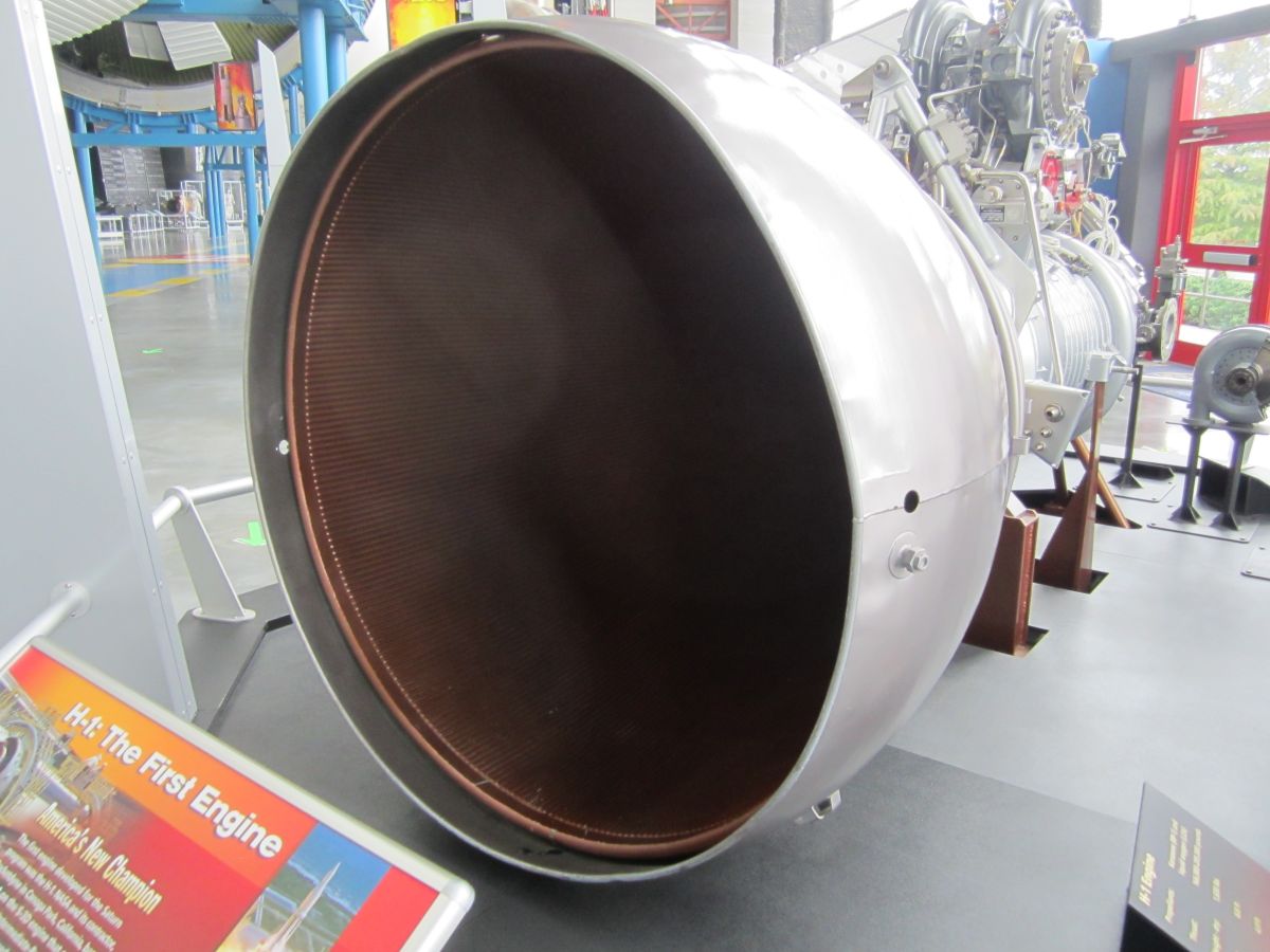
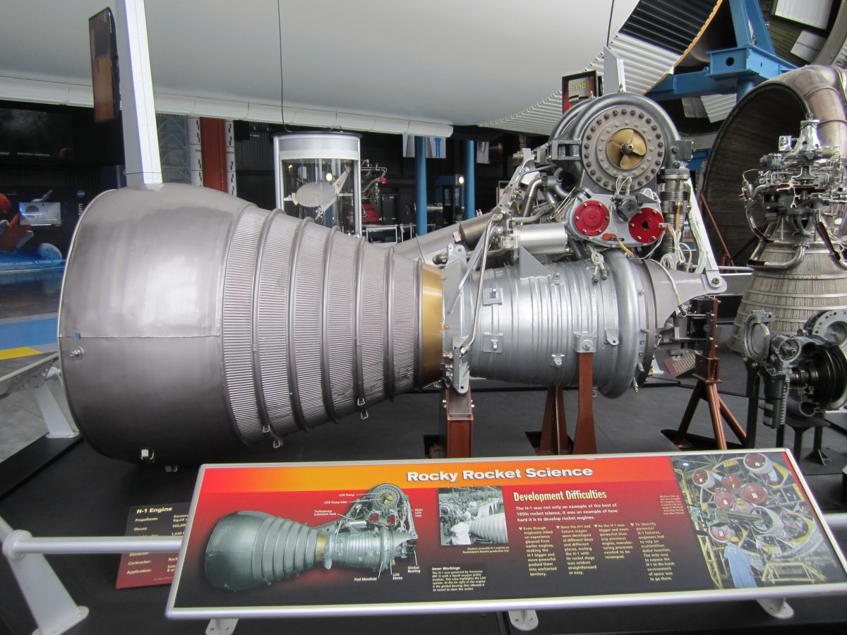
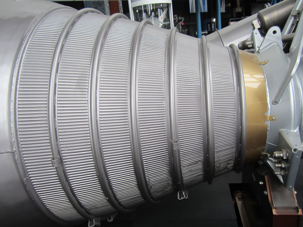
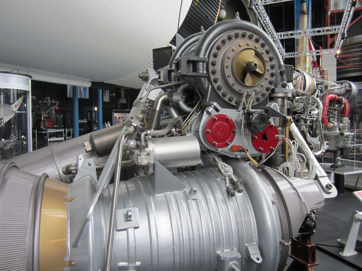
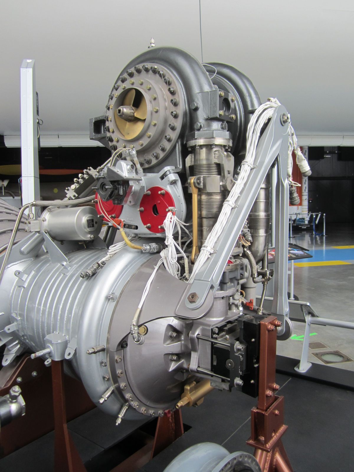
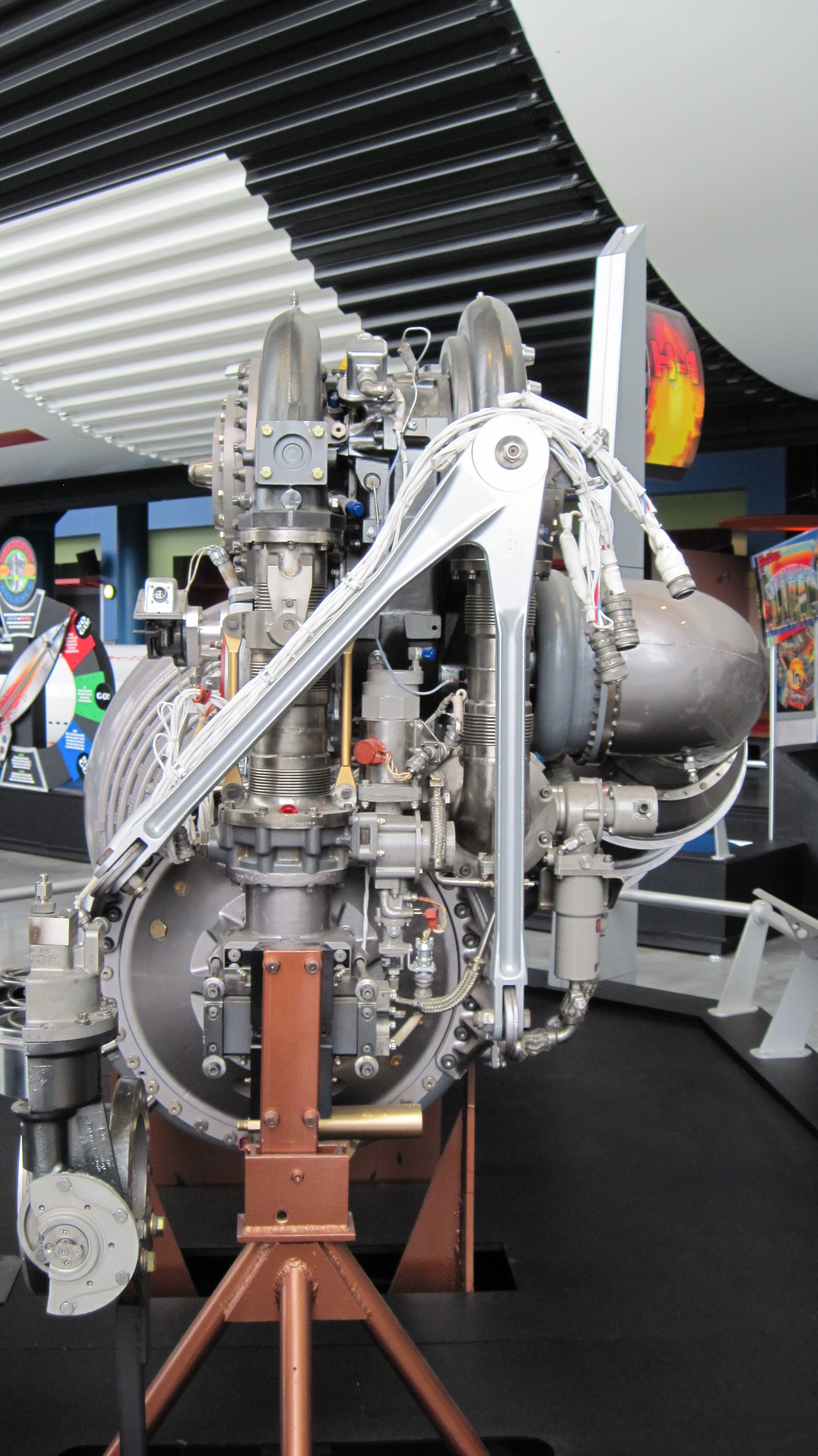
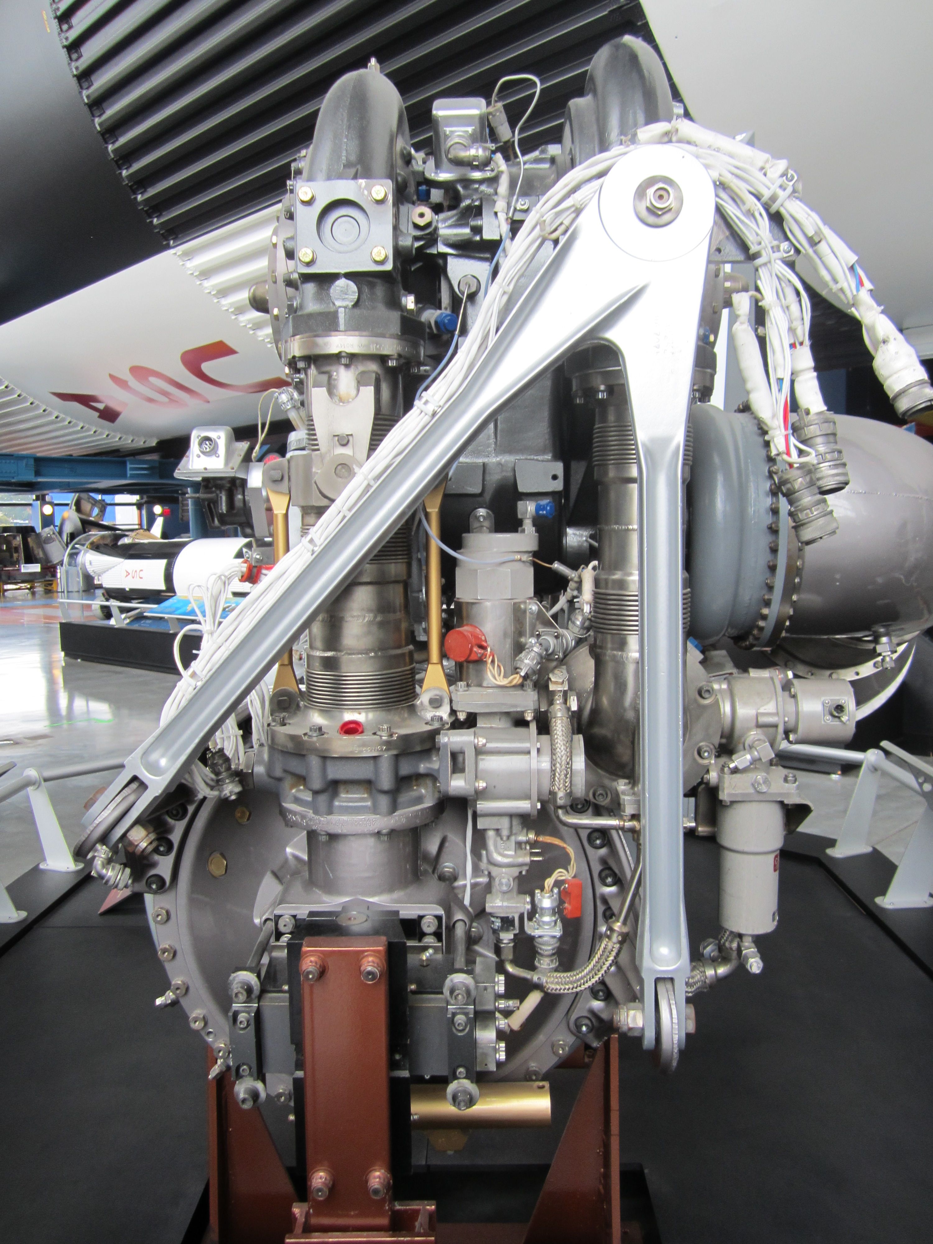
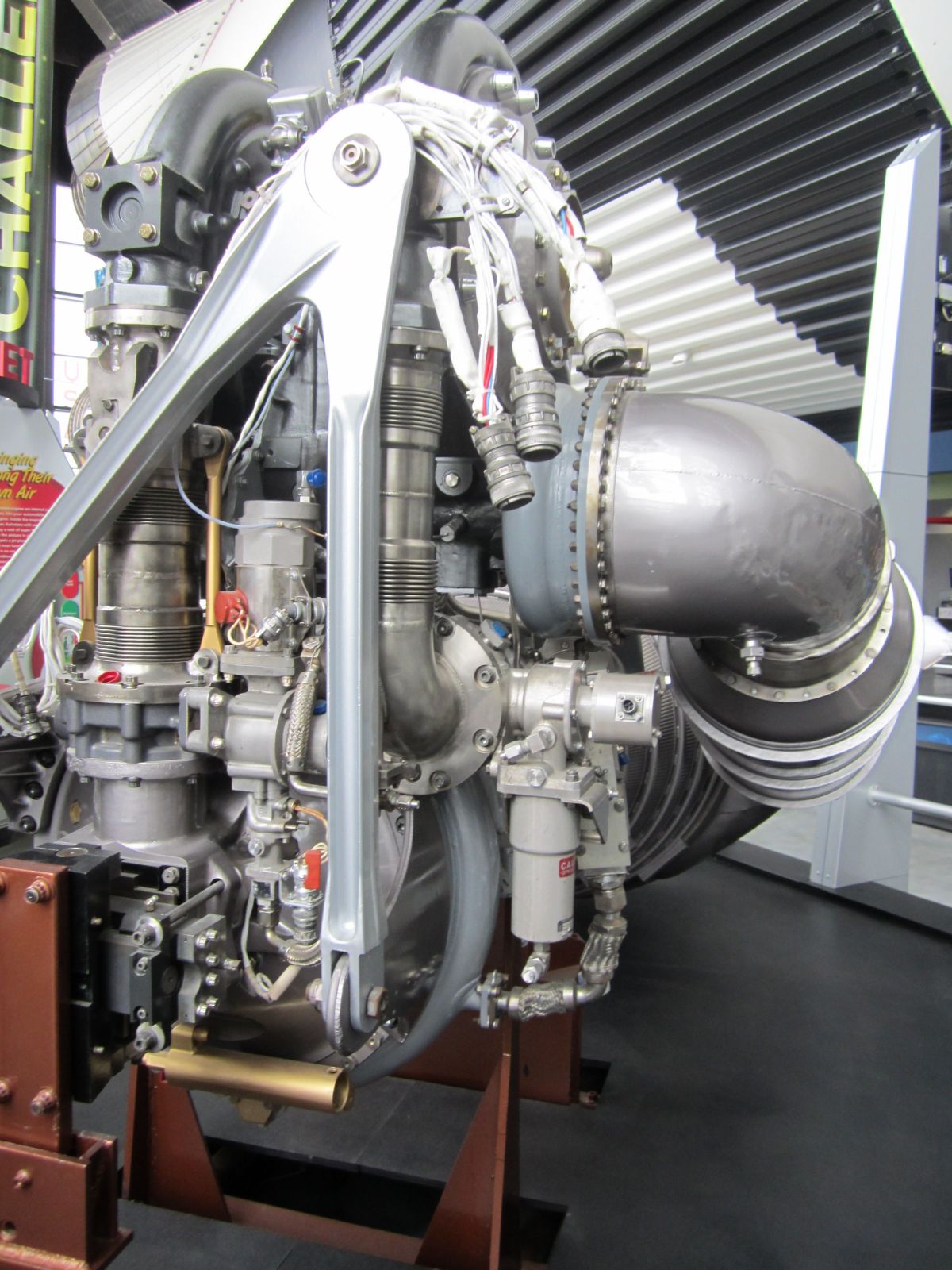
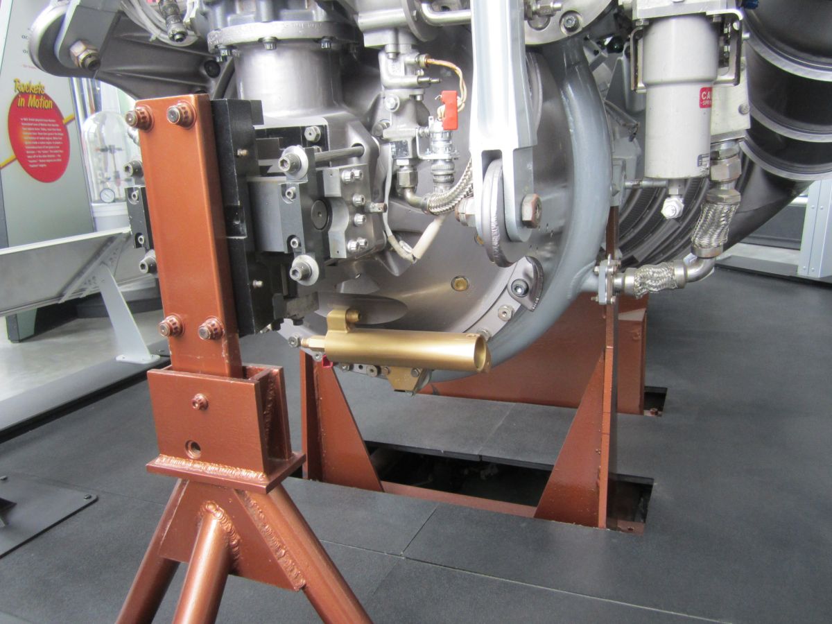
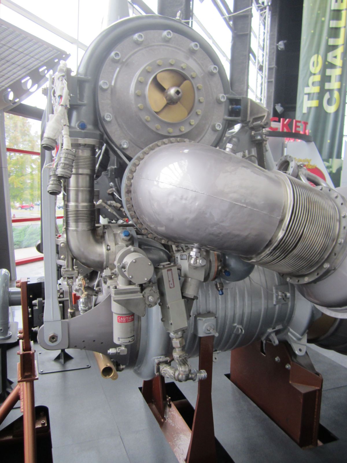
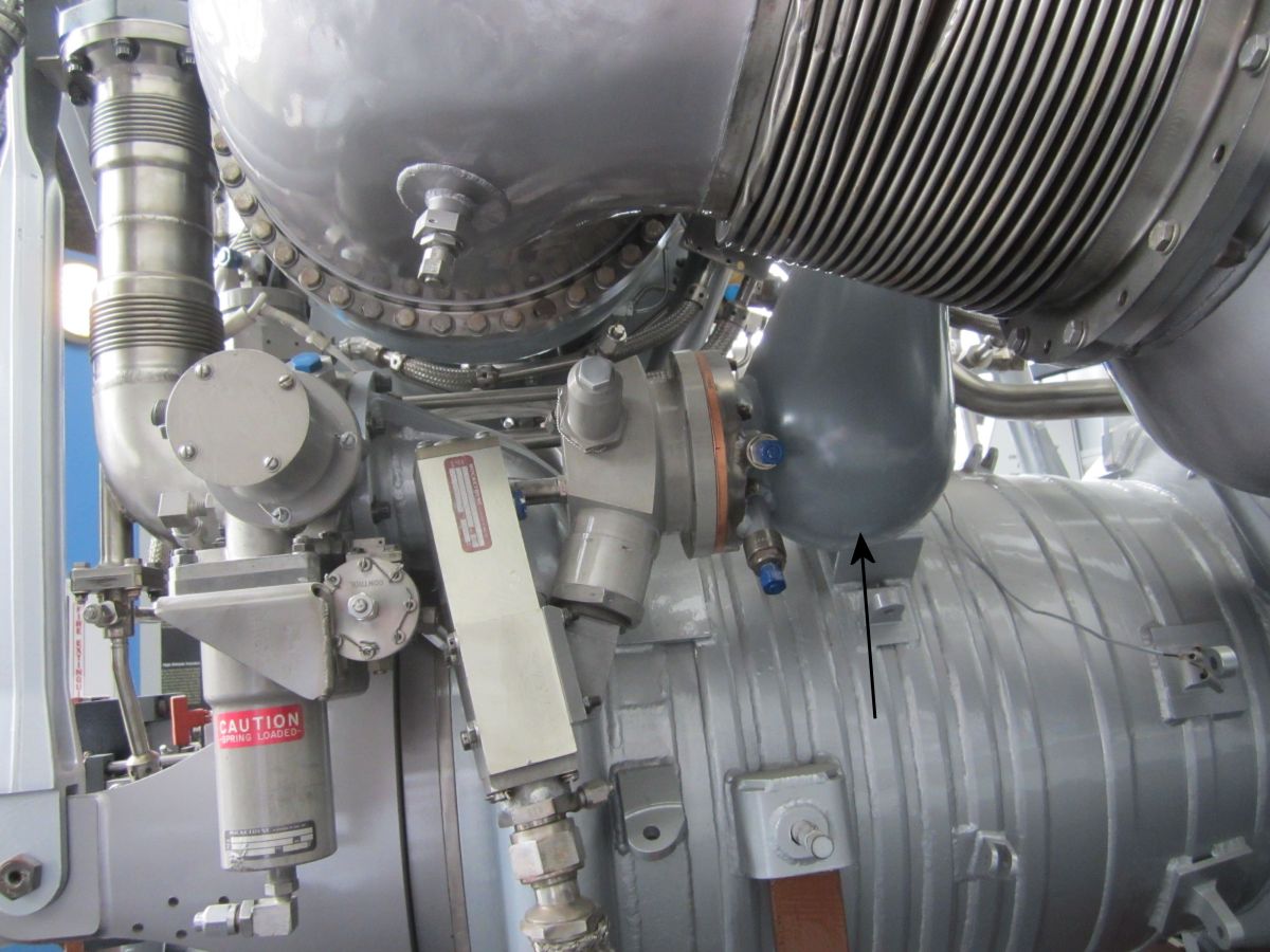
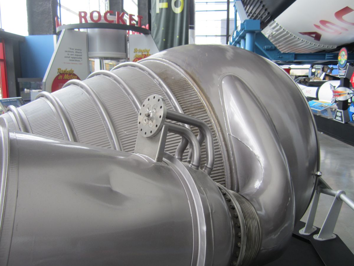
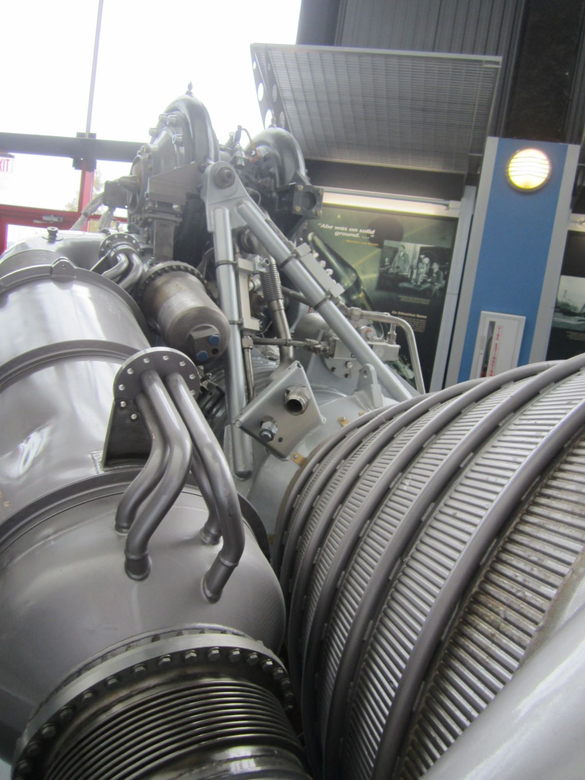
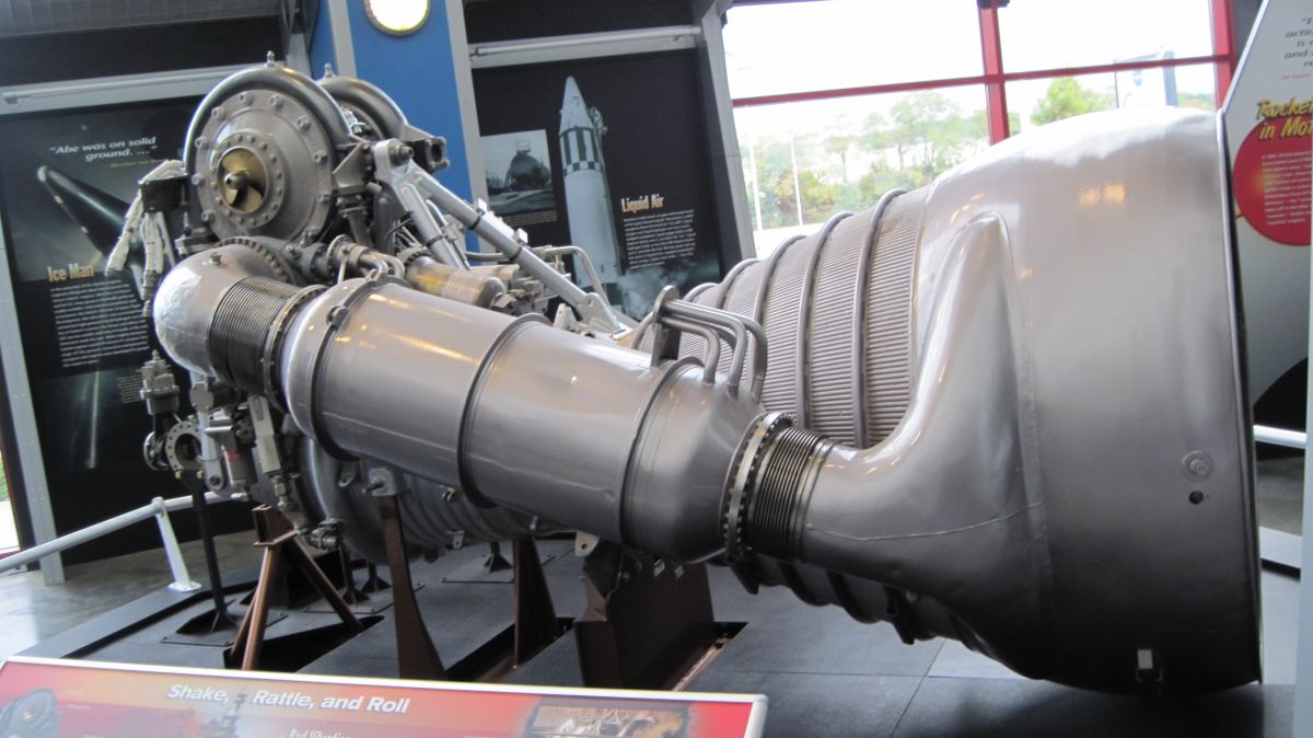
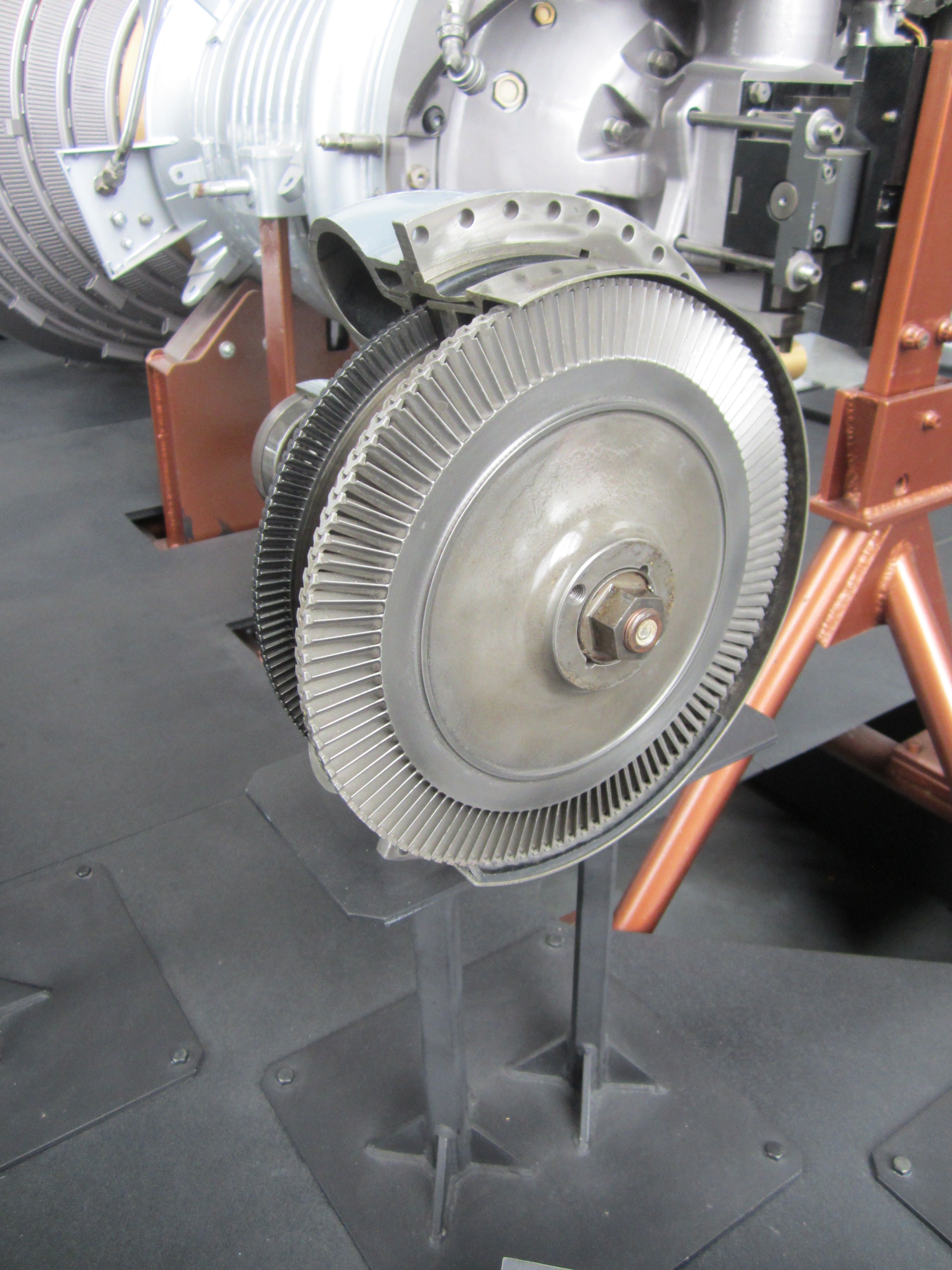
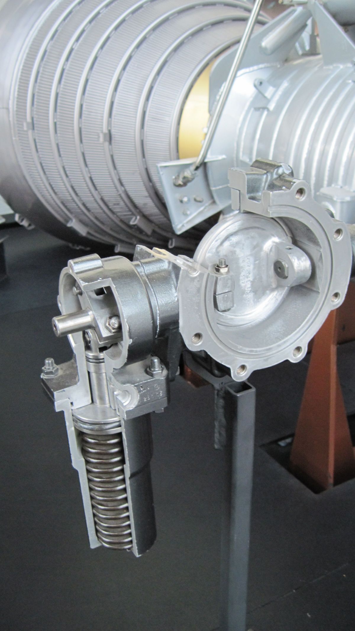
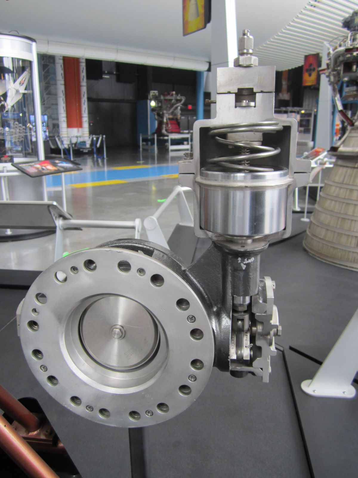
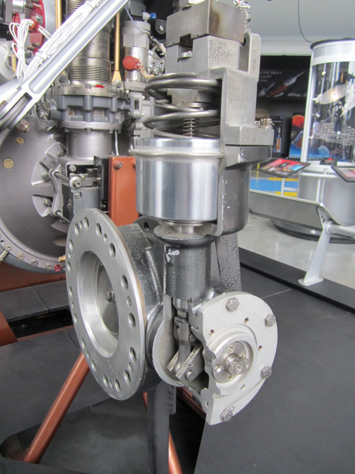
USSRC H-1D Walk Around
This early H-1D is displayed in the U.S. Space & Rocket Center Saturn V Hall.
 |
 |
 |
 |
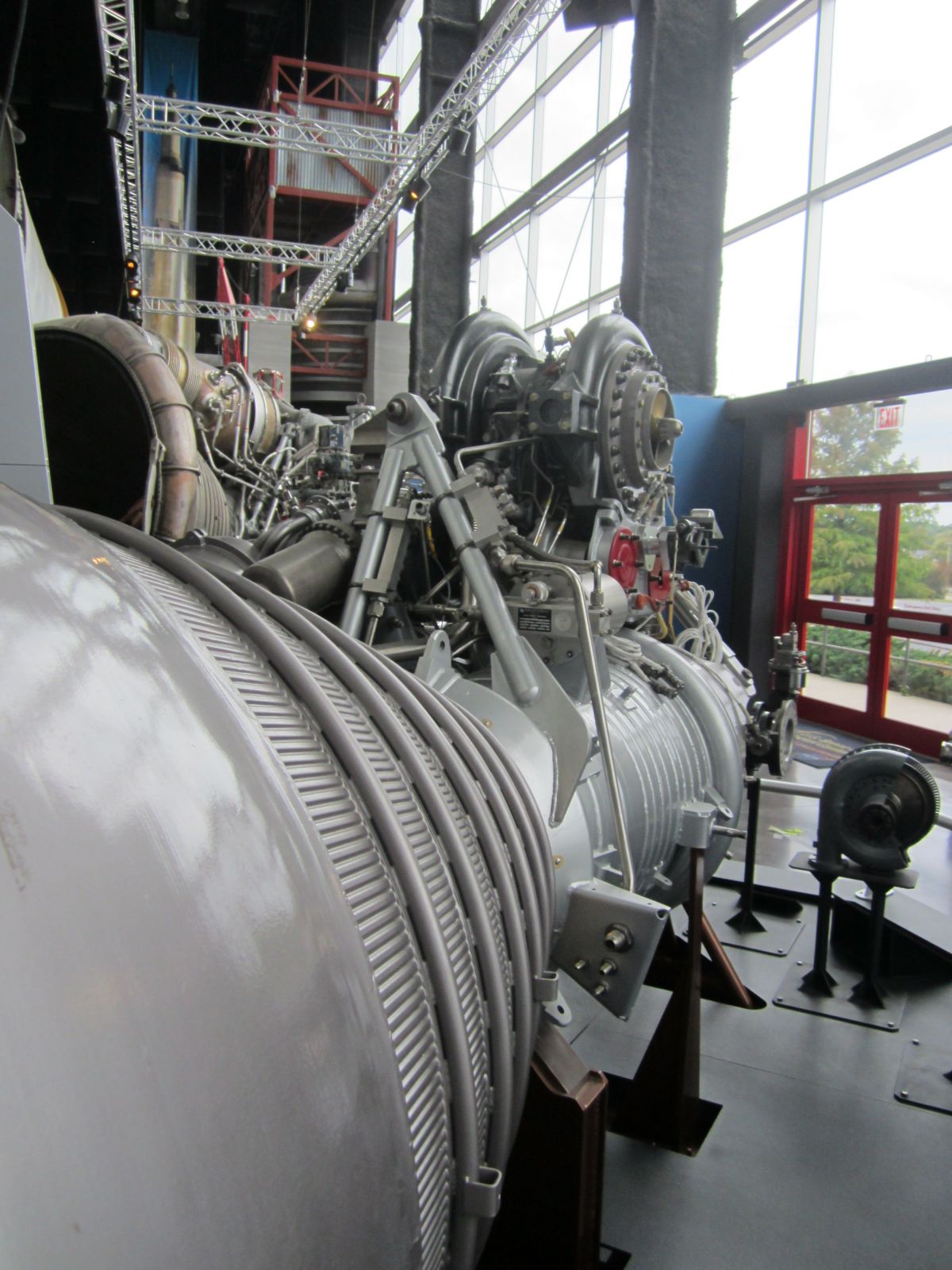 |
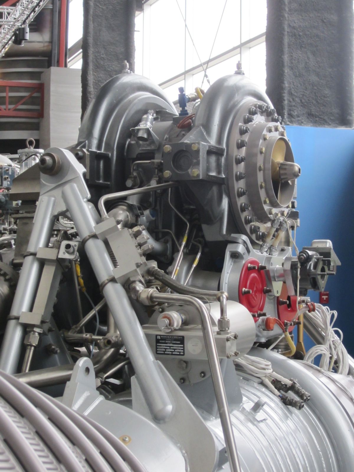 |
| Nozzle Exit | Aspirator Detail | Overall View | Thrust Chamber Construction | Turbopump and Control | Turbopump |
 |
 |
 |
 |
 |
 |
| LOX Pump | LOX Pump | Engine Top | Engine Top | Engine Top | Hypergol Cartridge |
 |
 |
 |
 |
 |
 |
| Fuel Pump | Gas Generator | Heat Exchanger Plumbing | Heat Exchanger Plumbing | Overall View | Turbine (S-3D) |
 |
 |
 |
 |
 |
 |
| Turbine (S-3D) | Turbine (S-3D) | Main Fuel Valve | Main LOX Valve | Main LOX Valve | Main LOX Valve |
| Engine | Model 39 | Rocketdyne 75-110-A-7 | Rocketdyne LR89-5 | Rocketdyne LR105-5 | Aerojet LR87-AJ-7 | Aerojet LR91-AJ-7 | Rocketdyne H-1D |
|---|---|---|---|---|---|---|---|
| Used In | German V-2 | Redstone | Atlas E, F Booster | Atlas E, F Sustainer | Titan GLV Stage 1 | Titan GLV Stage 2 | Saturn I, IB |
| Era | 1943 | 1953 | 1960 | 1960 | 1962 | 1962 | 1961 |
| Thrust, SL (lb) | 55,000 | 82,977 | 163,211 | 60,473 | 212,827 | 50,627 | 204,300 |
| Thrust, Vac (lb) | ? | 93,565 | 184,905 | 86,866 | 244,165 | 100,000 | 213,051 |
| Burn Time (sec) | 60 | 155 | 135 | 430 | 139 | 180 | 150 |
| Chamber Pressure (psi) | 218 – 239 | 318 | 580 | 696 | 784 | 804 | 701 |
| Specific Impulse (sec) | 203 – 239 | 235 – 265 | 248 – 282 | 220 –316 | 258 – 296 | 160 – 316 | 255 – 289 |
| Propellant Flow (gps) | 33.5 | 41.3 | 47.7 | 20 | 81.3 | 26.9 | 93.5 |
| Propellant Flow (lb/sec) | 286 | 355 | 458 | 193.2 | 824 | 322 | 760 |
| Nozzle Expansion Ratio | 2.83 | 3.61 | 8 | 25 | 8 | 45 | 8 |
| Engine Weight (lb) | 2,484 | 1,479 | 1,580 | 1,010 | 1,571 | 1,245 | 1,399 |
| Thrust / Weight, SL | 22 | 56 | 103 | 60 | 136 | 80 | 146 |
| Fuel | 75% Ethanol | 75% Ethanol | RP-1 | RP-1 | A-50 | A-50 | RP-1 |
| Oxidizer | LOX | LOX | LOX | LOX | N2O4 | N2O4 | LOX |
| Mixture Ratio (Ox/Fuel) | 1.13 | 1.324 | 2.21 | 2.25 | 1.9 | 1.79 | 2.34 |
| Turbopump Output (hp) | 580 | 758 | 3,140 | 1,663 | 5,180 | 2,122 | 4,021 |
| Turbine RPM | 3,800 | 4,718 | 30,986 | 30,000 | 25,172 | 23,685 | 6,680 |
References
Bilstein, Roger E. Stages to Saturn NASA SP-4206 (Washington, DC: NASA History Office, 1996)
H-1 Rocket Engine Models H-1C and H-1D Technical Manual (Conoga Park, California: Rocketdyne, 1966)
--- On To Part 8.00 ---
Send mail to
![]() with questions or comments about this web site.
with questions or comments about this web site.
![]()