U.S. Manned Rocket Propulsion Evolution
Part 1: Introduction
Compiled by Kimble D. McCutcheon
Published 1 Oct 2020; Revised 27 Aug 2023
 |
This series will explore liquid-fueled rocket engines that are part of the U.S. Space & Rocket Center collection, and that launched humans into space, and/or sent them to the moon and back to earth. This will include engines that were instrumental in technology development, such as the German V-2 and Navaho missile, along with human-rated launch systems, such as Redstone, Atlas, Titan, Saturn I, Saturn V and Space Shuttle.
From 1943 through 1968, U.S. rocket engineers achieved a nearly 30X increase in thrust with an extremely good reliability record. This was accomplished primarily by increasing combustion chamber pressure and advancing associated enabling technologies.
Rocket engines are deceptively simple in concept; fuel and oxidizer are combined under high pressure and set alight. The resulting high-speed gas stream is ejected, producing thrust. But as with most things, the devil is in the details, and it is in those details that true rocket science emerges.
The first article in this series introduces the principles, nomenclature and metrics necessary to compare the rocket engines discussed. This requires mathematical formulae to be accurate. I promise that after this first article, no further formulae will appear. If the reader wishes to avoid the math, just skip this part, and refer back to it for a definition or to review a concept. |
Principles, Nomenclature and Metrics
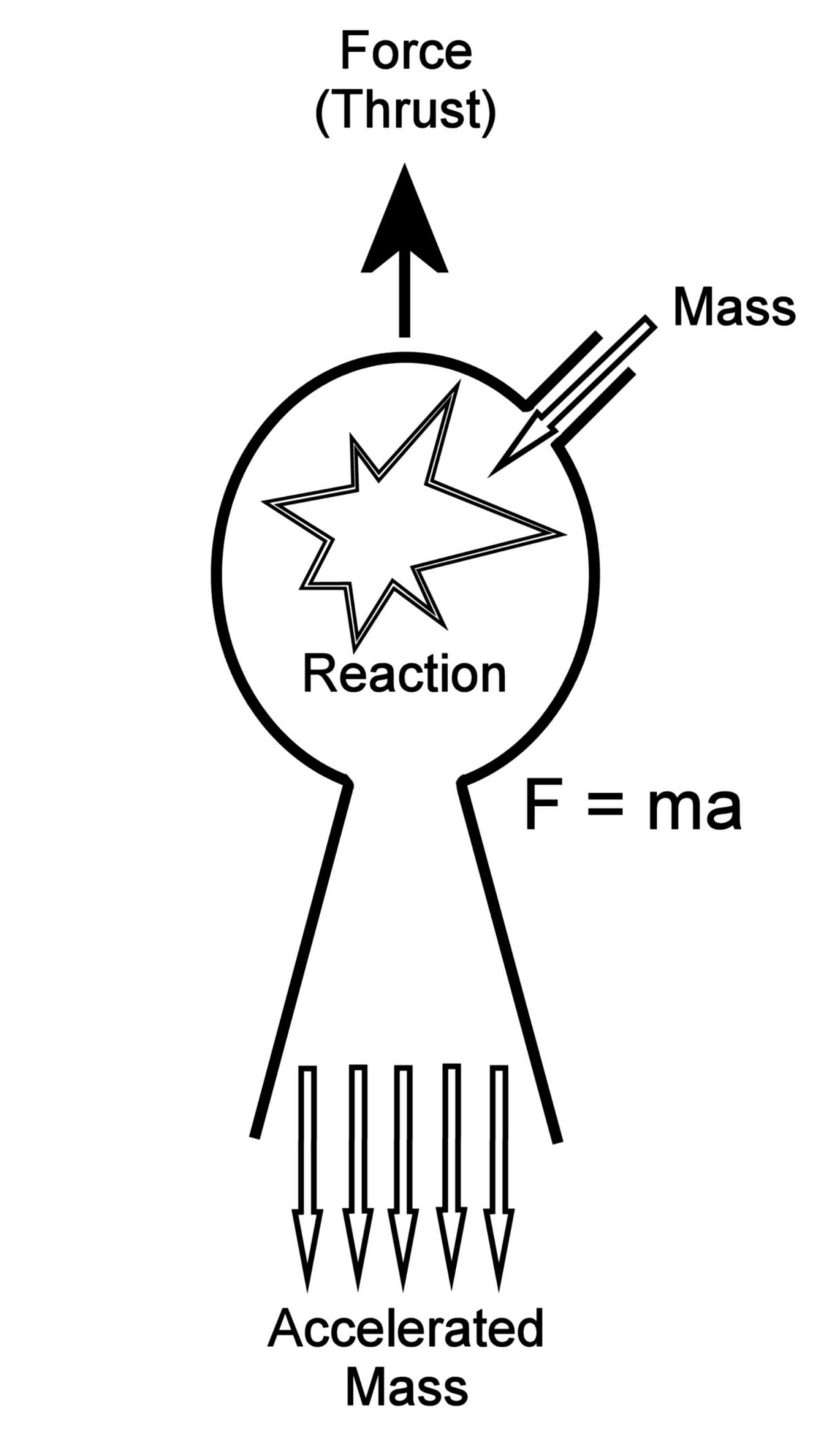
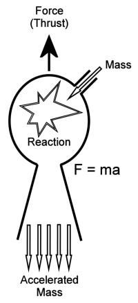
Thrust
Rocket engines produce thrust by exploiting Newton's second law of motion, F=ma, which says that force (thrust) is equal to propellant mass times the acceleration involved, via combustion, in ejecting that mass from the engine at somewhere between 6,000 and 12,000 feet per second (fps). The acceleration can be quantified thusly:
a = (Ve – V0) / t
where a = acceleration in feet per second per second (fps²), Ve = exit velocity in fps, V0 = initial velocity in fps, and t = the time required for the acceleration to occur. By substituting this acceleration formula into the original second motion law and performing some algebra, we arrive at
F = (m / t)(Ve – V0)
The term (m / t), or propellant mass per second, is further simplified by the symbol ṁ (m-dot), and since V0 is usually assumed to be equal to zero, and since it is convenient for our purposes to express the mass in pounds instead of slugs, the final equation becomes
F = (ṁ / g)Ve, where g is the acceleration of gravity, about 32.2 fps²
Another factor also contributing to thrust is the difference between ambient pressure, Pa and nozzle exit pressure, Pe, over the nozzle exit area Ae. In space where Pa = 0, and in well-designed nozzles where Pe = Pa, this thrust difference is minimal, but for the sake of completeness, the full formula is
F = (ṁ / g)Ve + (Pe - Pa)Ae
Note that in the atmosphere, if the nozzle is operating suboptimally, thrust arising from this second term may actually be negative.
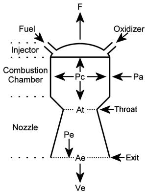 |
| Rocket Engine Thrust Chamber |
Chamber Pressure (Pc)
As seen in the thrust equation above, thrust increases with increasing Ve, and Ve is related to combustion chamber pressure; the higher the chamber pressure, the greater the thrust. As usual, nothing is free and with increased chamber pressure comes increased stress on the engine components, particularly the pumps, valves and propellant ducts. Additionally, increased chamber pressure also increases the thrust chamber wall heat loads.
Specific Impulse (Isp)
Specific impulse is a measure of a rocket engine's efficiency. It is essentially the thrust per pound of propellant consumed per second.
Isp = F / ṁ, where Isp is the specific impulse in seconds
Although a rocket designer might be tempted to always use the highest Isp propellant combination available, the propellant density is also a factor. For example, the Saturn I and Saturn V first stage boosters use a propellant combination of kerosene and liquid oxygen (LOX). Why not liquid hydrogen (LH2) and LOX? Despite the propellant combination having a better Isp, since LH2 is so much less dense, it requires a much larger (~66% larger!) booster to accomplish the same goal.
Mixture Ratio (MR)
The ratio of oxidizer to fuel is the mixture ratio. Maximum Isp is theoretically achieved when the MR is stoichiometric; practically this is often not the case. For example, the Space Shuttle Main Engine, which burns LH2 and LOX, has a stoichiometric MR of 8. However the actual MR is about 6. This hydrogen-rich burn reduces combustion temperature and leaves a small amount of free H2 in the exhaust, which, because it is a lighter molecule than H20, can be accelerated to a higher velocity. This high-velocity H2 in the exhaust gives the hydrogen-rich MR an Isp advantage over a stoichiometric MR.
Nozzle Area Ratio (ε)
The area ratio or nozzle expansion ratio is defined as
ε = Ae / At
As ε increases the exit velocity increases and the exit pressure decreases, resulting in greater Isp. Nozzles are designed with ε values that will produce optimal thrust, i.e. Pe = Pa. If Pe > Pa the nozzle is underexpanded; if the reverse is true, the nozzle is overexpanded. Rocket engines that operate only in the vacuum of space tend to have large values of ε; those operating in the atmosphere have values of ε that are a compromise since they are only optimal at one altitude. Engineers have considered nozzles with variable ε, but the complexity to achieve this is rarely warranted.
Other Metrics
Several other metrics are useful in comparing propulsion systems and charting their evolution.
- Propellant flow rates, in both pounds per second and gallons per second, are useful in understanding the large masses handled.
- Turbopump turbine output, in horsepower, provides an idea of the power required to pump propellants at the required rates and pressures.
- Turbine rpm is another metric that allows charting of turbopump progress.
- Burn time, in seconds, helps one grasp the length of time that an engine must produce its tremendous power.
- Engine weight in pounds allows one to track improvements in engine construction.
- Thrust-to-weight ratio is useful in comparing engines.
Hopefully the metrics appearing above will be sufficient to compare the rocket propulsion systems to be discussed.
Engineering Challenges
A rocket engineer faces many challenges in dealing with the incredible power, pressures and temperatures involved in rocket engine design and refinement.
Thrust Chamber Shape and Construction
The combustion chamber must have sufficient diameter to accommodate an injector that will deliver the required propellant mass flow. Its volume and length must be sufficient for burning to occur. Convergent nozzle section should accelerate the combustion gasses to sonic velocity at the throat; the divergent nozzle section increases gas acceleration while decreasing pressure, ideally to ambient by exit. Early divergent nozzles were conical but it was later discovered that a bell-shaped nozzle achieved essentially the same result with a shorter length and less weight.
Heat/Cooling
Rocket propellants burn at temperatures ranging from 4,500°F to 6,500 °F; steels melt at around 2,800°F. While some smaller liquid and solid-propellant engines are built with ablative liners (ones that burn away), metal thrust chambers must be cooled. Early engines accomplished this with double-walled thrust chambers, circulating some or all of the fuel between the liner and outer shell before it was burned. This is called regenerative cooling. Some also injected a few percent of the fuel through small holes drilled at intervals in the liner; this fuel evaporated and formed a vapor barrier that protected the liner from combustion heat. This is called transpiration or film cooling. Not only must the rocket engineer deal with extreme heat, but must also deal with extreme cold. LOX boils at -297°F; LH2 boils at -423°F.
Environment/Materials
Most things, including many metals, will burn in the presence of high-temperature, high-pressure oxygen. Early rocket engines used a combination of ethanol and water to help cool the thrust chamber components. This helped with protecting the relatively thick thrust chamber inner wall from burning through. The thick-walled thrust chamber was necessary to provide sufficient heat strength, but had the disadvantage of conducting heat poorly. Stainless steels are better at resisting the effects of high-pressure oxygen, but are even poorer heat conductors than carbon and alloy steels.
Pressure
One of the most important factors in a rocket engine's trust production is its chamber pressure. The combination of mass flow and combustion chamber pressure creates the gas acceleration that produces thrust. This value is measured in pounds per square inch absolute (psia), which is pressure relative to a vacuum instead of the more common pounds per square inch gauge (psi or psig) that is measured relative to atmospheric pressure. Chamber pressure has increased from a low value of about 220 psia in the German V-2 to more than 3,200 psia in the Space Shuttle Main Engine (SSME). Also of note is that the chamber pressure is the LOWEST pressure in the high-pressure portion of the propellant delivery system. In order to prevent burning gasses from flowing backwards into the plumbing and pumps, injector pressure must be even higher and turbopump pressure higher still. The creation and maintenance of the high pressures involved are some of the biggest challenges faced by rocket engine designers.
Combustion Instability
Ever watch a candle burn in a closed, draft-free room? It flickers. Combustion instability, the same mechanism that makes the candle flicker, also is a problem for rocket engines. Combustion instability in a rocket engine can set up vibration ranging from low-frequency chugging, to buzzing, to high-frequency screaming. Any of these frequencies may resonate with engine components and/or combustion chamber geometry to cause extremely rapid destruction. In addition, combustion instability can cause thrust chamber wall burn-through by setting up standing waves that affect specific zones. We shall see that nearly every rocket engine advance was troubled with combustion instability.
Propellant Delivery
The simplest propellant delivery system involves merely pressurizing the propellant tanks. Unfortunately, this scheme only works for fairly small rockets and low chamber pressures. With larger rockets propellant tanks that can stand the required pressure become too heavy. This is why most rocket engines employ some sort of mechanical pump. Even with mechanical pumps, propellant delivery systems must deal with the pressure changes that occur with changes in altitude from sea level to the vacuum of space. Engineers must also provide schemes to allow reliable engine operation in microgravity.
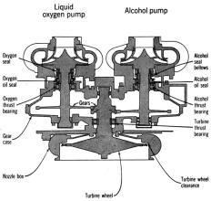
Turbopump Systems
One way to achieve the propellant flow rates and pressures required for high performance rockets is to use a device called a turbopump. As the name implies, this employs a turbine that drives a pump. Turbopumps come in many forms; some use a single turbine to drive both the fuel and oxidizer pumps, while others provide a separate turbine for each. In all cases, the turbine must be powered in such a way that pump output can be controlled. Some turbines are powered by steam generators that catalyze hydrogen peroxide, others by burning the engine propellants.
The pumps are no small feat either. They must deliver extremely high propellant volumes at high pressure. For example, the Rocketdyne F-1 engine used on the Saturn V first stage consumes about 674 gallons of propellant every second! Each SSME, which burns 225 gallons of propellant per second with a 3,200 psia chamber pressure, employs multiple turbopumps, with the High-Pressure Fuel Turbopump producing a pressure of 6,000 psia and some parts of the SSME High-Pressure Oxidizer Turbopump producing pressures as high as 8,000 psia. To pump at these flows and pressures, the turbines collectively produce over 104,000 hp! Think about that, over 104,000 hp JUST TO PUMP THE PROPELLANTS! By comparison, this is equivalent to the power of 69 M1 Abrams Main Battle Tanks.
Turbopumps must be very carefully designed to deal with hot turbines and cold pumps on the same shaft, prevent cavitation (vapor pockets caused by accelerating the fluid too fast), and be well sealed to keep the turbine driving gasses, fuel and oxidizer separated, all while running as fast as 40,000 rpm.
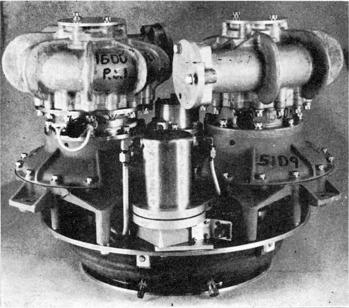
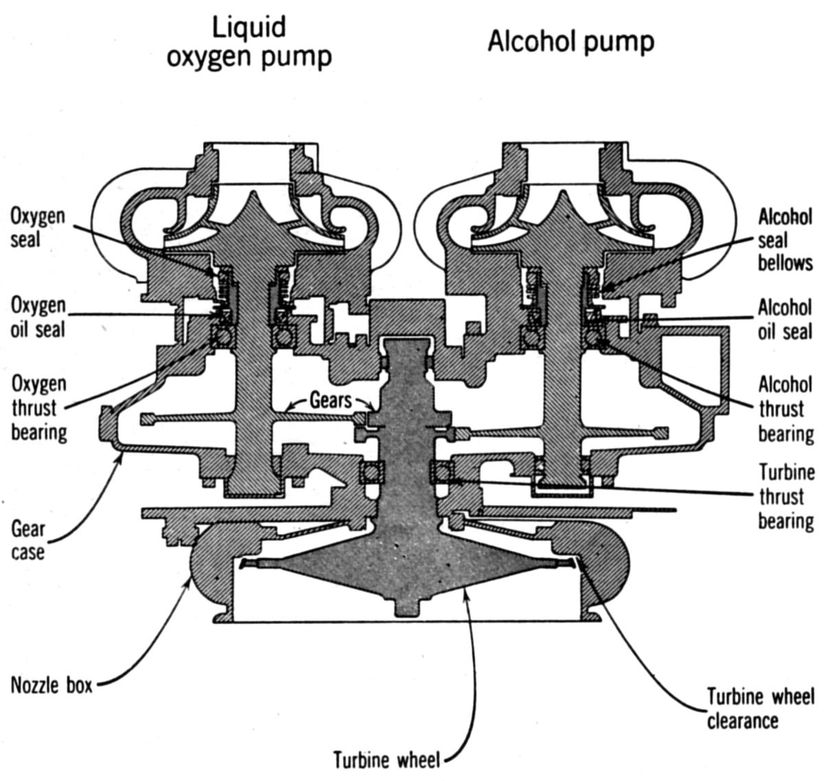
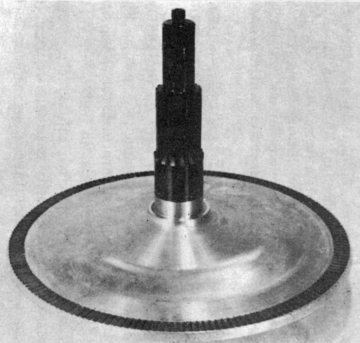
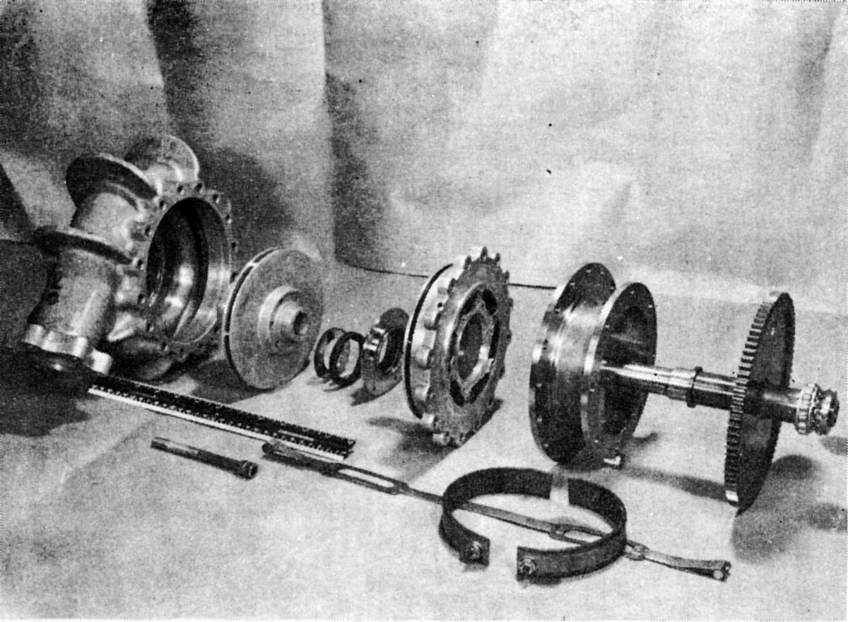
Early Hermes Missile Turbopump
 |
 |
 |
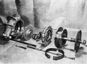 |
| Geared Turbopump Assembly |
Cross Section |
Turbine |
LOX Pump |
Control
Rocket engines operation typically proceeds through three phases: Start, Mainstage, and Shutdown. Each phase has its own challenges.
Perhaps the most challenging thing one can do to a rocket engine is to start it. Going from idle to full power in a few seconds requires careful control and sequencing of valves and igniters so that everything proceeds in an orderly fashion, which is to say, without creating an explosion. The start process proceeds slowly in rocket engine time, often proceeding incrementally to full power. Learning how start an new engine often results in blowing a few up.
Most rocket engines are designed to maintain stability during mainstage. Those that can be throttled present special issues.
Shutting down an engine is a simpler version of starting, but must still be accomplished in an orderly way.
Auxiliary Subsystems
We have discussed the principle systems comprising most rocket engines. There may also be numerous subsystems.
- A drain subsystem to route leaked propellant
- A purge subsystem to remove air and other undesirable substances
- A pneumatic subsystem to operate valves
- An ignition subsystem to ignite gas generators and main combustion
- A spin-start subsystem to initially spin the turbopump(s)
- A tank pressurization subsystem to provide pump head pressure, replenish burned propellant volume and compensate for changes in external pressure as altitude increases.
- A bleed system to pre-fill engine components with propellants prior to start
Each subsystem has its own unique challenges, and as we shall see, even the minor subsystems can have catastrophic consequences.
Onward
Now that the reader has been dragged through the math and terminology presented above, In future installments we shall see how various rocket designers rose to the numerous challenges.
--- On To Part 2.1 ---