Apollo 16
Command Module
U.S. Manned Rocket Propulsion Evolution
Part 9.20: The Apollo Command Module Reaction Control System
Compiled by Kimble D. McCutcheon
Published 5 Oct 2021; Revised 25 Jul 2024
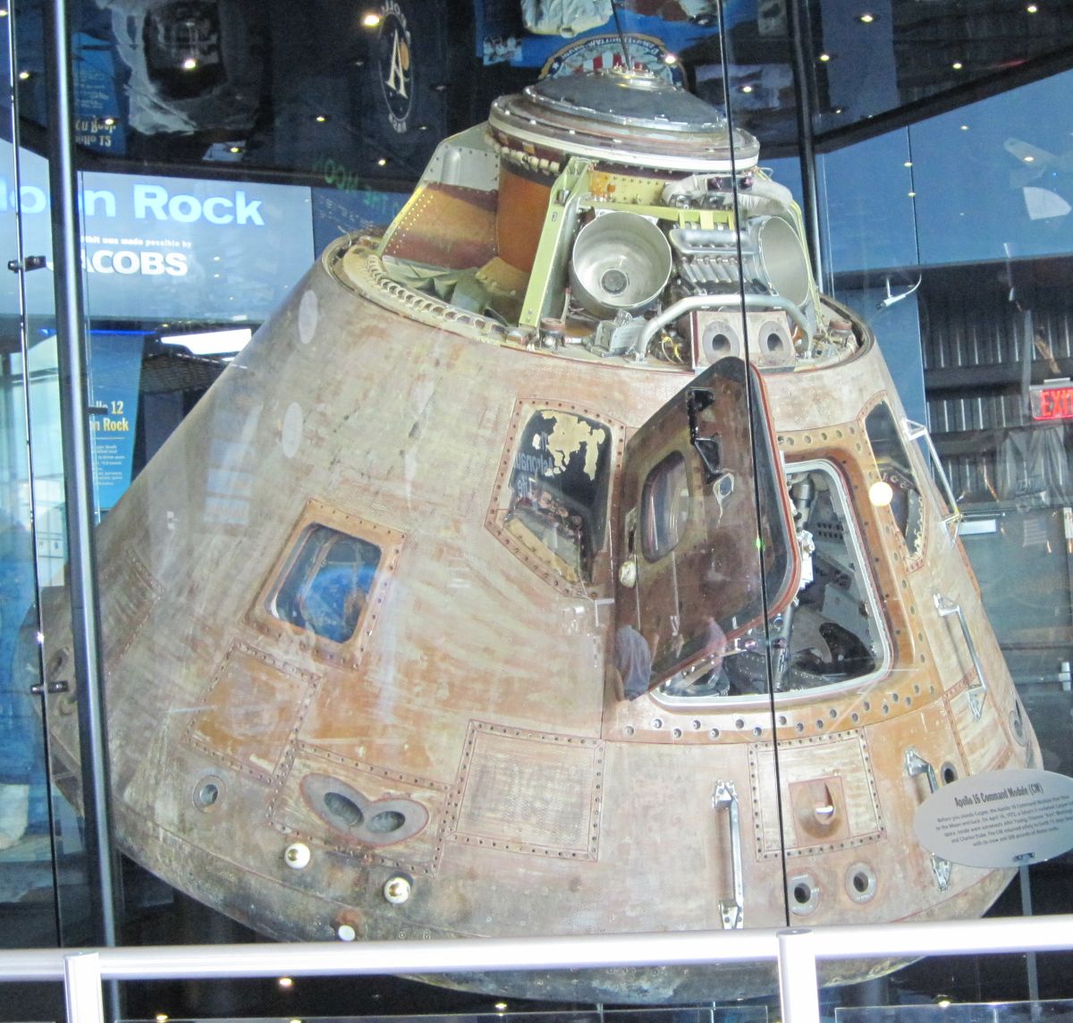
Apollo 16 Command Module |
The Apollo Command Module (CM) was stupefyingly complex, providing for all the crew's needs for an 8 – 12 day mission. Yet it was not needlessly complex — there were no frills, only the minimum provisions to accomplish the mission, along with redundant critical systems. Because of the CM's complexity, we shall limit this discussion to the propulsion-related CM features, namely the reaction control system (RCS), which provided thrust for normal and emergency CM attitude control maneuvers. The RCS operated in response to automatic control signals from the stabilization and control subsystem in conjunction with the guidance and navigation subsystem. The crew could also manually control the RCS. |
Overview
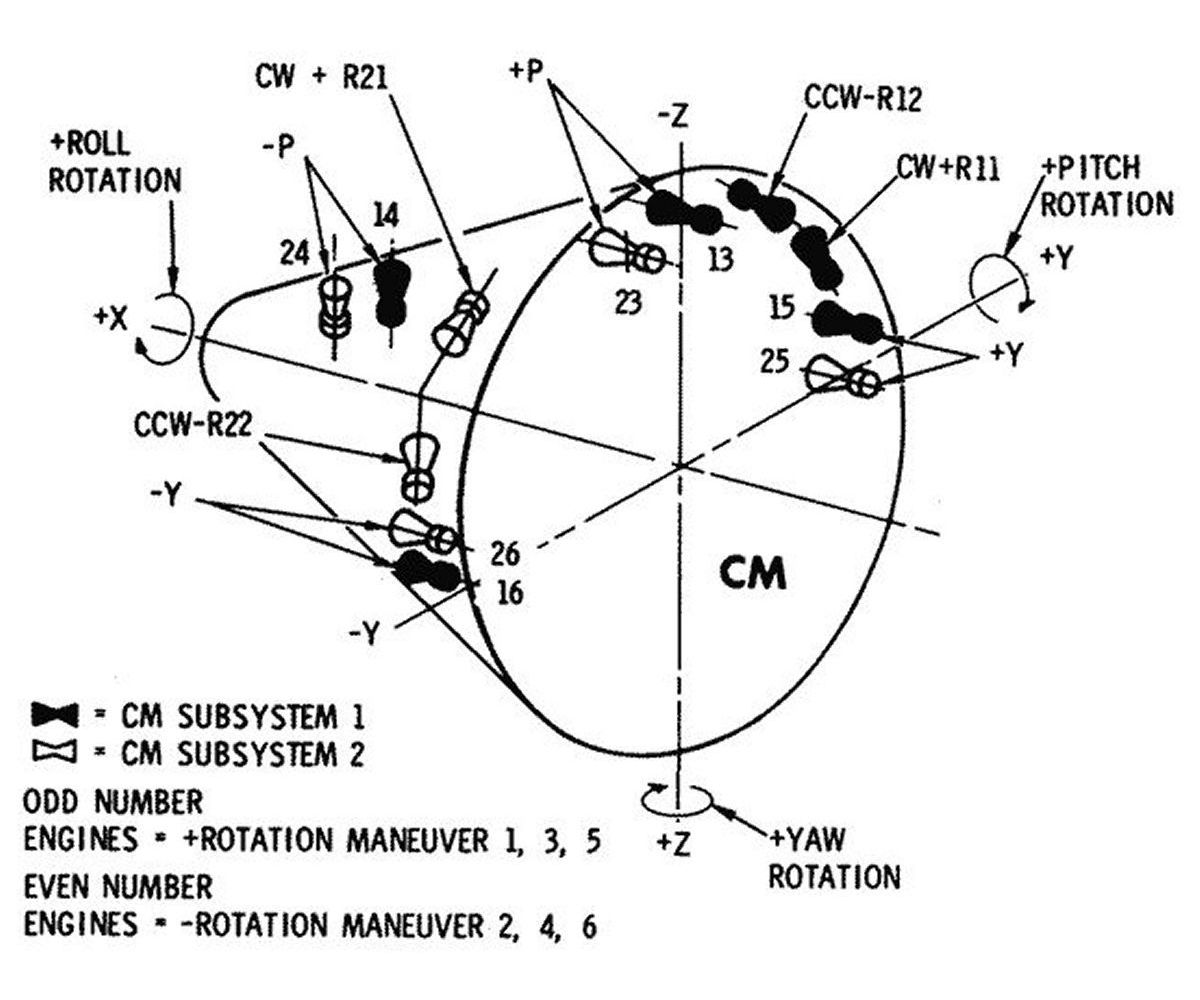
The CM RCS was used after CM-service module separation and for certain abort modes. It provided three-axis attitude control to keep the CM oriented in the proper reentry attitude before encountering aerodynamic forces. Once the CM was in the atmosphere the RCS provided the torque necessary to control roll. Since the CM center of pressure was offset from its center of gravity, roll maneuvers could provide limited control over entry angle and cross-range excursion. The CM RCS consisted of two independent, redundant systems that could operate in parallel; however, one could provide all the impulse needed for the entry maneuvers and normally only one was used.
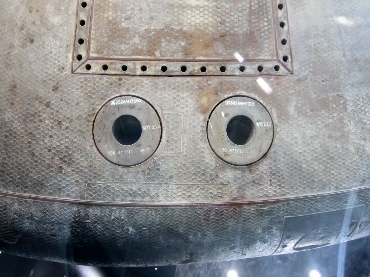
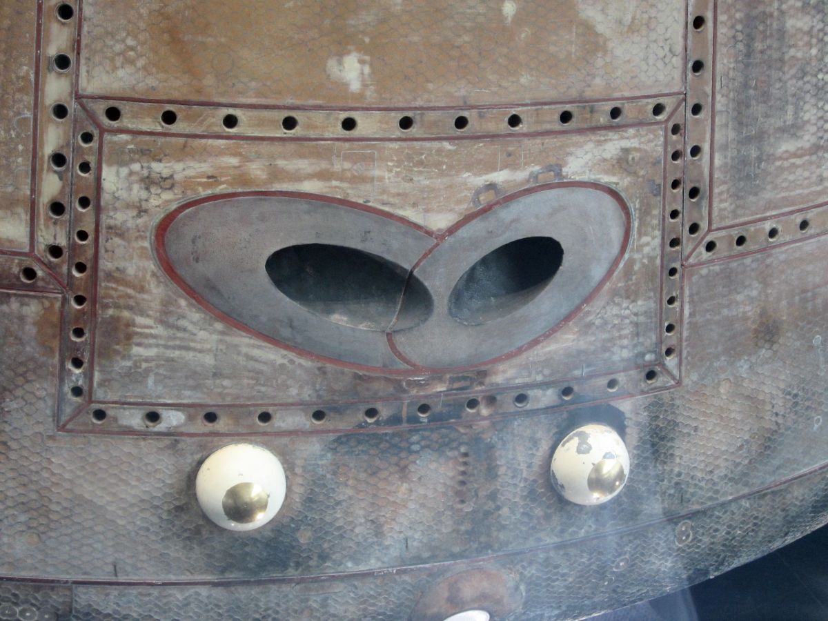
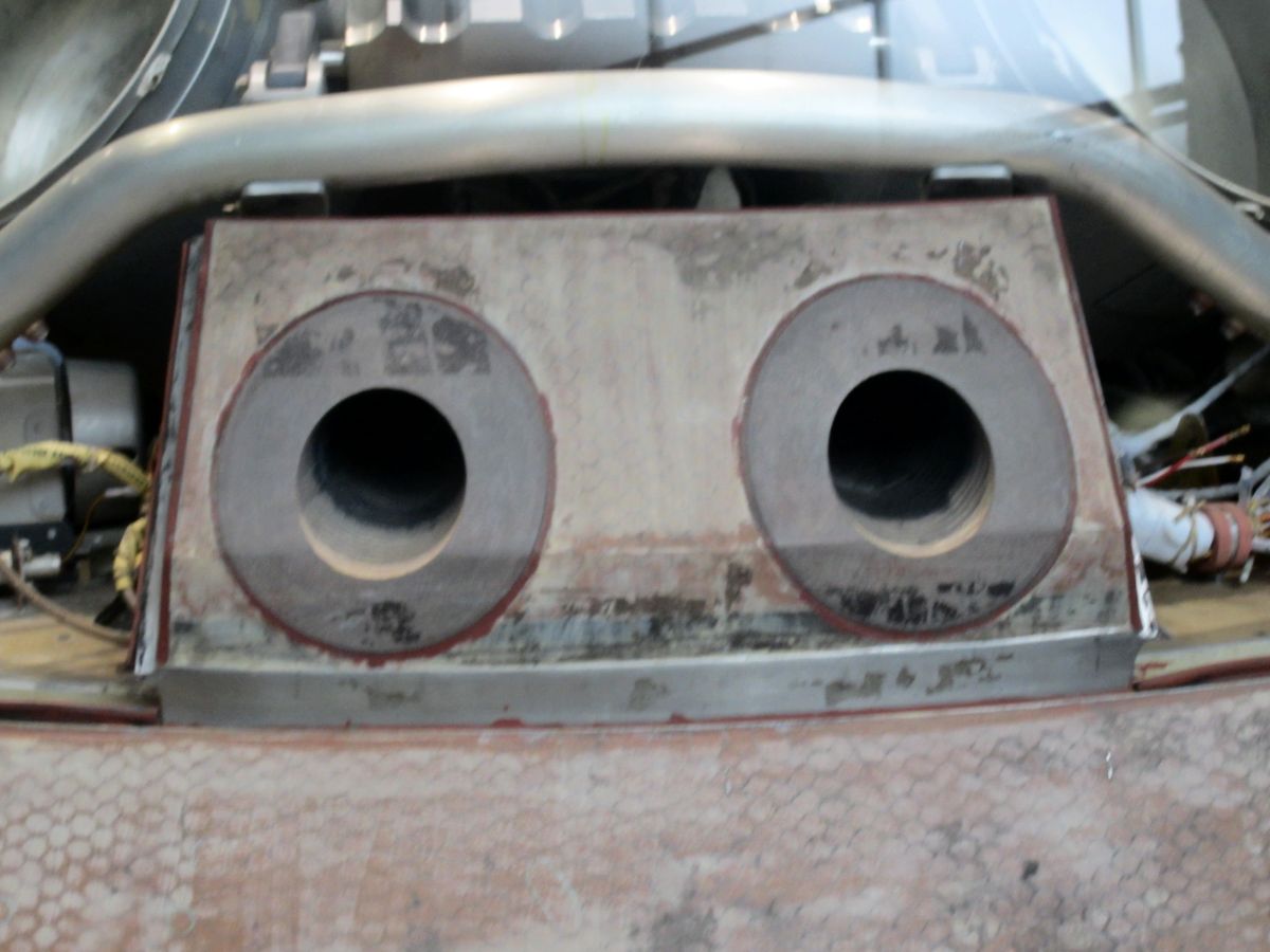
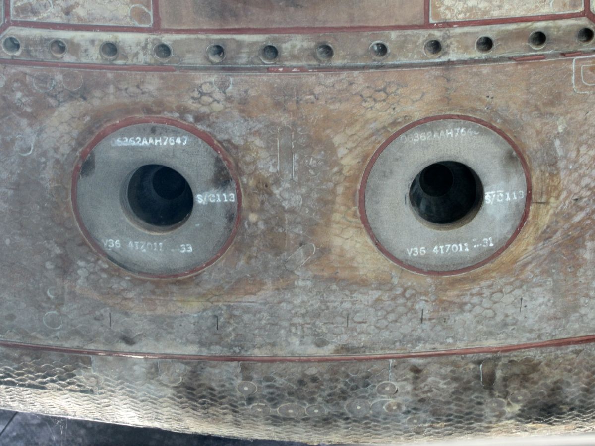
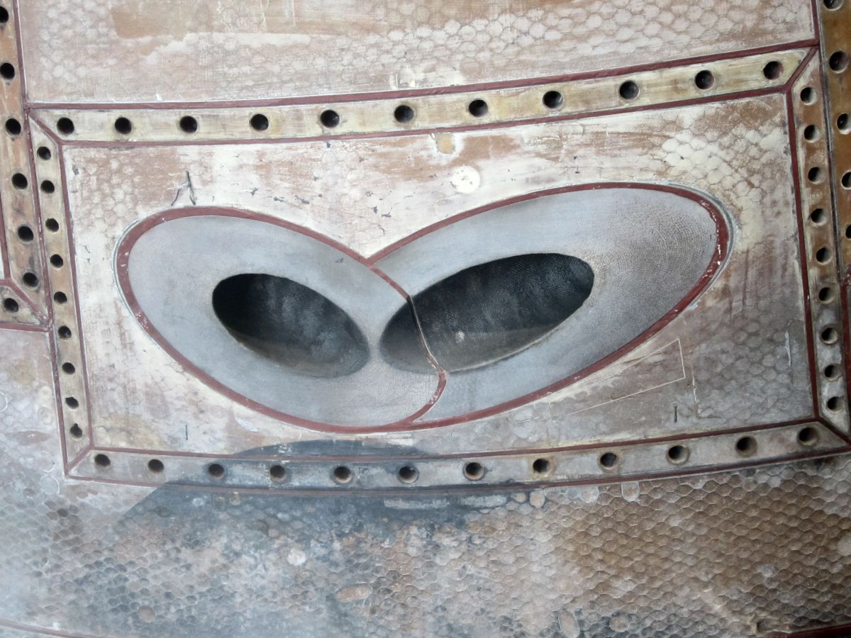
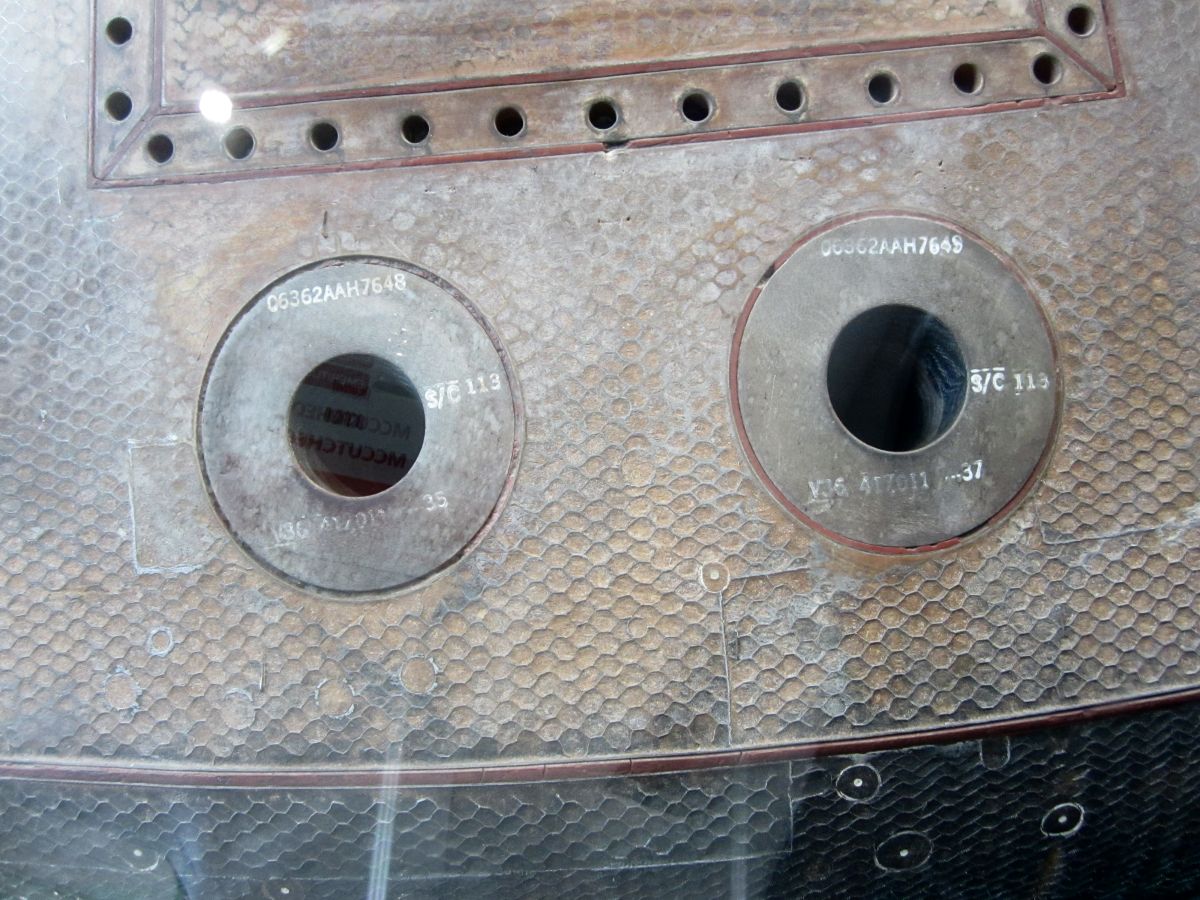
The system's 12 engines were located outside the CM crew compartment; 10 engines were in the aft compartment and 2 in the forward compartment. Each engine's nozzle was ported through the CM's heat shield and matched the mold line. Each engine produced about 93 lbT and was fueled by monomethyl hydrazine (MMH) and used nitrogen tetroxide (N2O4) as the oxidizer.
Since both fuel and oxidizer were hazardous to rescue personnel after CM splashdown, propellant remaining in the fuel and oxidizer tanks was burned to dispose of it during the final descent on the main parachute. After all propellant was burned the feed lines were purged with helium. The burn and purge operations were controlled manually by the crew except during an abort in the early part of boost (up to 42 seconds after liftoff), when dumping and purging was automatic.
CM RCS Components
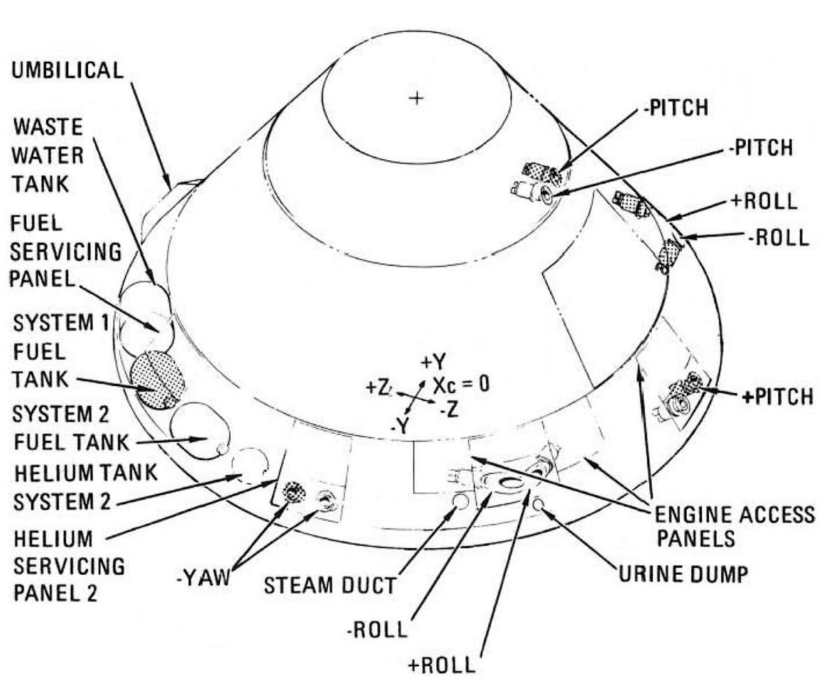
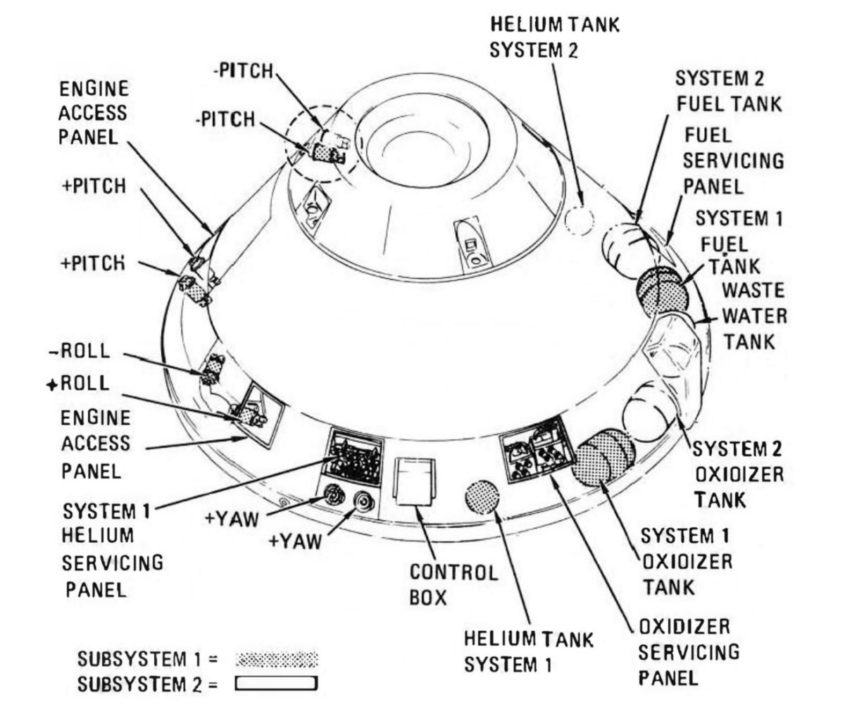
Two spherical titanium helium tanks, manufactured by the Menasco Manufacturing Co., of Burbank, California, stored helium to pressurize the propellant tanks. Each helium tank had a volume of 365 in³ and was pressurized to 4,150 psig. Each tank had an outside diameter of 9.2" and wall thickness of 0.102". Capacity of each was 0.57 lb.
Two titanium fuel tanks, manufactured by Bell Aerosystems Co. of Buffalo, New York, stored MMH and supplied it to the RCS engines upon demand. These cylindrical tanks had domed ends, were 17.329" long and 12.65" in diameter; wall thickness was 0.022 - 0.027". Combined propellant and ullage volume was 45.2 pounds, resulting in tank pressure ≤ 205 psia at 105°F.
Two titanium oxidizer tanks, manufactured by Bell Aerosystems Co. of Buffalo, New York, stored N2O4 and supplied it to the RCS engines upon demand. Each tank was 19.907" long and 12.65" in diameter; wall thickness was 0.022 - 0.027". Combined propellant and ullage volume was 89.2 pounds, resulting in tank pressure ≤ 205 psig at 105°F.
Each tank contained a diffuser tube assembly and a Teflon bladder for positive propellant expulsion. The bladder was attached to the diffuser tube at each tank end so that propellant exited via the diffuser tube. When the tank was pressurized, helium gas surrounded the entire bladder, exerting a force that caused the bladder to collapse about the propellant, forcing it into the diffuser tube assembly, out of the tank outlet, and into the manifold.
Twelve ablatively-cooled SE-8 engines, built by North American Rockwell's Rocketdyne Division, of Canoga Park, California, were used for rotation maneuvers, rate damping, and attitude control during reentry. Installed with scarfed ablative nozzle extensions, the CM RCS engines were 12.65" long and weighed 8.3 lb. Nozzle exit diameter was 2.13". Each engine's service life was 200 seconds and 3,000 operational cycles. Minimum firing time was about 12 ms.
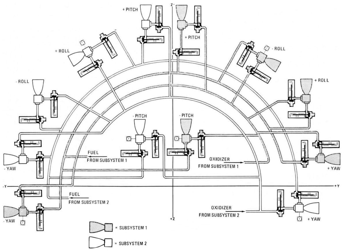
 |
 |
 |
| Orientation | Component Location | Component Location |
 |
 |
 |
 |
 |
 |
| - Yaw Nozzle Exits | Port Roll Nozzle Exits | - Pitch Nozzle Exits | + Pitch Nozzle Exits | Starboard Roll Nozzle Exits | + Yaw Nozzle Exits |
CM RCS Operation
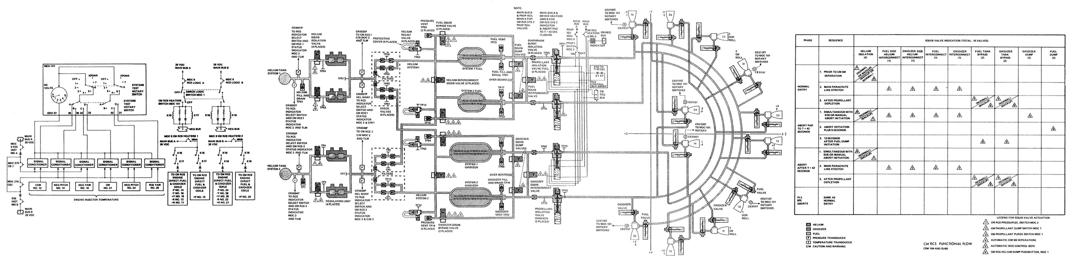
The CM RCS was composed of two separate, identical, normally independent systems, called System 1 and System 2. Each contained pressurization, propellant, rocket engines and temperature control subsystems.
The pressurization subsystem consisted of a helium supply tank, two dual pressure regulators, two check valves, two pressure relief valves, and associated distribution plumbing. Two squib-operated helium isolation valves installed in each helium tank's plumbing confined the helium into as small an area as possible to reduce helium leakage until the system was used. Helium pressure was regulated by two regulator assemblies connected in parallel, with each assembly downstream of an isolation valve. Each regulator assembly incorporated a primary and a secondary regulator, connected in series. The secondary regulator remained open when the primary regulator functioned properly. If the primary regulator failed open, the secondary regulator maintained acceptable pressure. The CM primary and secondary regulators were set to 291 psia.
 |
| Command Module Reaction Control System Functional Schematic |
 |
| Squib Valve |
One oxidizer and one fuel check valve assembly permitted helium flow to the tanks but prevented propellant or propellant vapor from flowing into the pressurization subsystem if propellant tank bladder seepage or failure occurred. Each check valve assembly inlet and each test port incorporated a filter.
The helium relief valve contained a diaphragm, filter, bleed device, and the relief valve. The diaphragm was installed to provide a more positive seal against helium than that of the actual relief valve. The diaphragm ruptured at 340 psia. The filter retained any fragments from the diaphragm and prevented particles from flowing onto the relief valve seat. The relief valve opened at 346 psia and dumped excessive pressure overboard. The relief valve reseated at 220 psia.
A pressure bleed device vented the cavity between the diaphragm and relief valve in the event of any leakage across the diaphragm, or upon completion of relief valve checkout. The bleed device was normally open but fully closed when the pressure increased to 150 psia; it was again fully opened when the pressure decreased to 20 psia. Helium pressure forced propellants into the feed lines, through a burst diaphragm, and to the engines. The burst diaphragm had to rupture for propellant to reach the engines, which was additional assurance against inadvertent firing. Once the burst diaphragms ruptured, propellant flowed to the propellant isolation valves. These were controlled by a single switch on the CM main display console. Each propellant isolation valve contained two solenoids, one that was energized momentarily to magnetically latch the valve open, and one that was energized momentarily to unlatch the magnetic latch. Spring force and propellant pressure closed the valve. An indicator on the main display console showed gray indicating that the valves were open (the normal position) and diagonal lines when either valve was closed. The valves were closed in the event of a line rupture or runaway thruster.
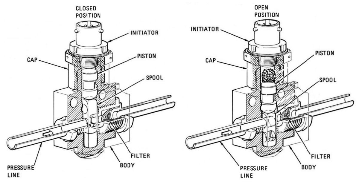
The distribution lines contained 16 squib valves that permitted the helium and propellant distribution configuration to be changed for various functions. Each squib valve was actuated by an explosive charge detonated by an igniter. After ignition of the squib the valve remained permanently open. Two squib valves were used in each subsystem to isolate the high-pressure helium supply. Two squib valves were used to interconnect System 1 and 2 regulated helium supply, which assessed pressurization of both systems during dump-burn and helium purge operation. Two squib valves in each subsystem permitted helium gas to bypass the propellant tanks and allow helium purging of the propellant subsystem. One squib valve in the oxidizer system permitted both oxidizer systems to become common. One squib valve in the fuel system permitted both fuel systems to become common. Two squib valves in the oxidizer system and two in the fuel system were used to dump their respective propellant in the event of an abort from the pad up to 42 seconds after liftoff.
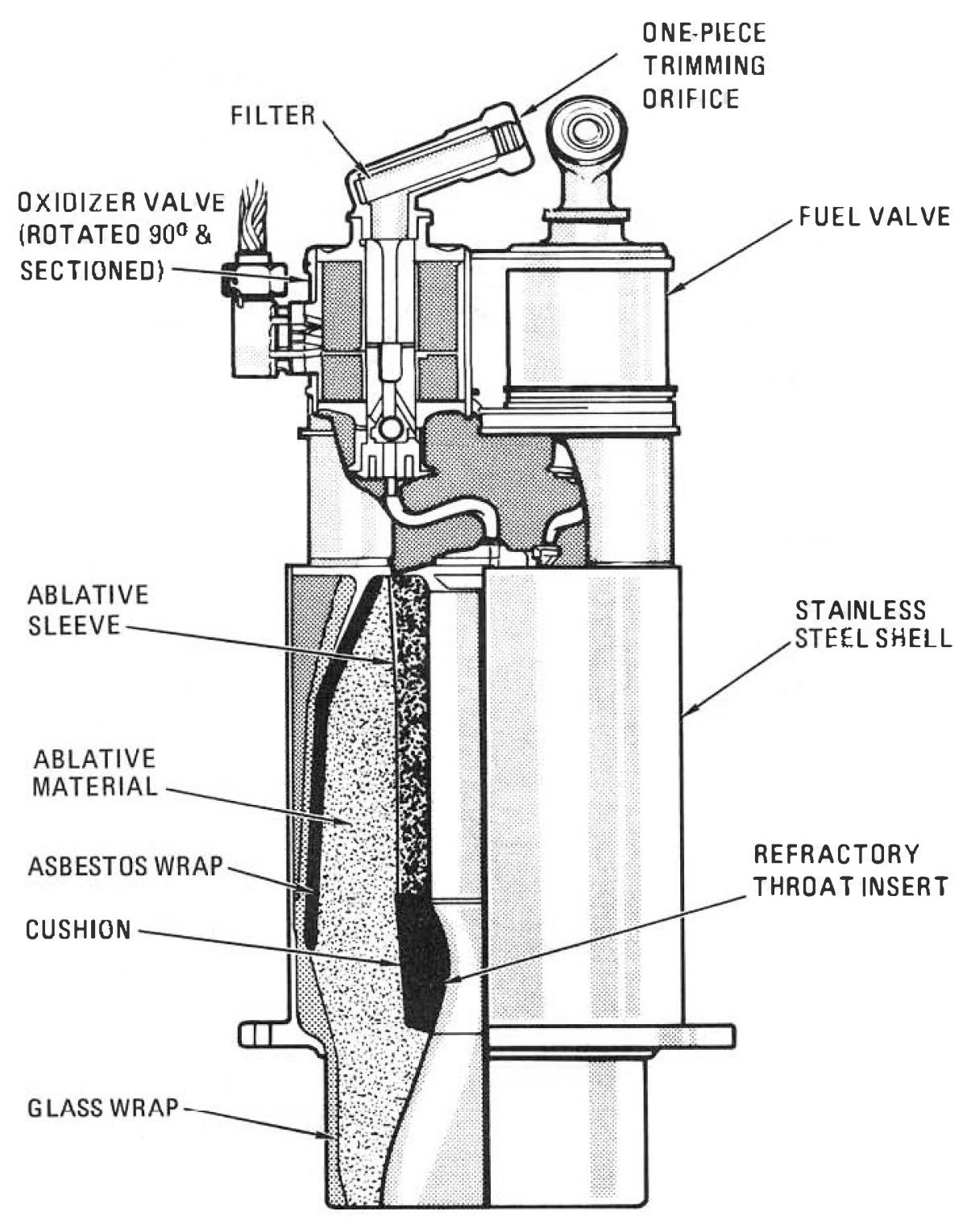 |
| RCS Engine |
The ablatively-cooled CM RCS engines could be operated in either pulse or steady-state mode. Each engine consisted of fuel and oxidizer injector valves that controlled propellant flow, an injector and a combustion chamber in which the propellants were burned to produce thrust. Each engine's injector valves contained metering orifices that ensured a 2:1 oxidizer-to-fuel)flow ratio. The injector valves used two coaxial Tally-wound coils, one for automatic and one for direct manual control. The automatic coil was used when the thrust command originated in guidance and control electronics. The direct manual coil was used when the thrust command originated at the astronaut hand rotation control. The engine injector valves were spring-loaded closed and energized open. The automatic coils in the fuel and oxidizer injector valves were connected in parallel from guidance and control electronics. The direct manual coils in the fuel and oxidizer injector valves provide a direct backup to the automatic system. They were connected in parallel.
The injector contained 16 fuel and 16 oxidizer passages that impinged on a splash plate within the combustion chamber. This pattern was referred to as an unlike impingement splash-plate injector. The thrust chamber assembly consisted of the combustion chamber ablative sleeve, throat insert, ablative body, asbestos, and a fiberglass wrap. The CM RCS engines were mounted within the CM structure. The nozzle extensions pierced the CM heat shield and were made of ablative material. Their exits matched the CM mold lines.
CM engine temperature before activation was controlled by energizing injector valve direct coils on each engine. Temperature sensors were mounted on 6 of the 12 engine injectors. The temperature transducers had a range from -50° to +50°F. The temperature transducers from the System 1 and 2 engine injectors provided inputs to two rotary switches located in the CM lower equipment bay. The specific engine injector temperature was monitored as DC voltage on the voltmeter in the bay. If any one of the engines registered less than 48°F, the direct manual heating coils of all 12 engines were switched on. If 48°F (approximately 5 volts on the do voltmeter) was reached from the coldest instrumented engine before 20 minutes, the valves were turned off. If 20 minutes passed before +48°F was reached, the valves were then turned off. The heaters prevented the oxidizer from freezing at the engine injector valves and the 20-minute time limit assures that the warmest engines would not be overheated.
All automatic thrust commands for CM attitude were generated from the controller reaction jet assembly. These commands could originate at the rotation controls, the stabilization and control subsystem, or the CM computer. If the controller reaction jet assembly was unable to provide commands to the automatic coil of the CM engines, switches on the main display console could provide power to the rotation controls for direct coil control. The CM-SM separation switches automatically energized relays in the RCS control box that transferred the controller reaction jet assembly and direct manual inputs from the SM engines to the CM engines. These functions also occurred automatically on any launch escape subsystem abort.
The control box transfer motors were redundant to assure that the direct manual inputs were transferred from the SM engines to the CM engines, in addition to providing a positive deadface. The RCS transfer motors could also be activated by a transfer switch placed to "CM" position; this was a manual backup to the automatic transfer. CM Systems 1 and 2 could be checked out before CM-SM separation by use of the transfer switch.
 |
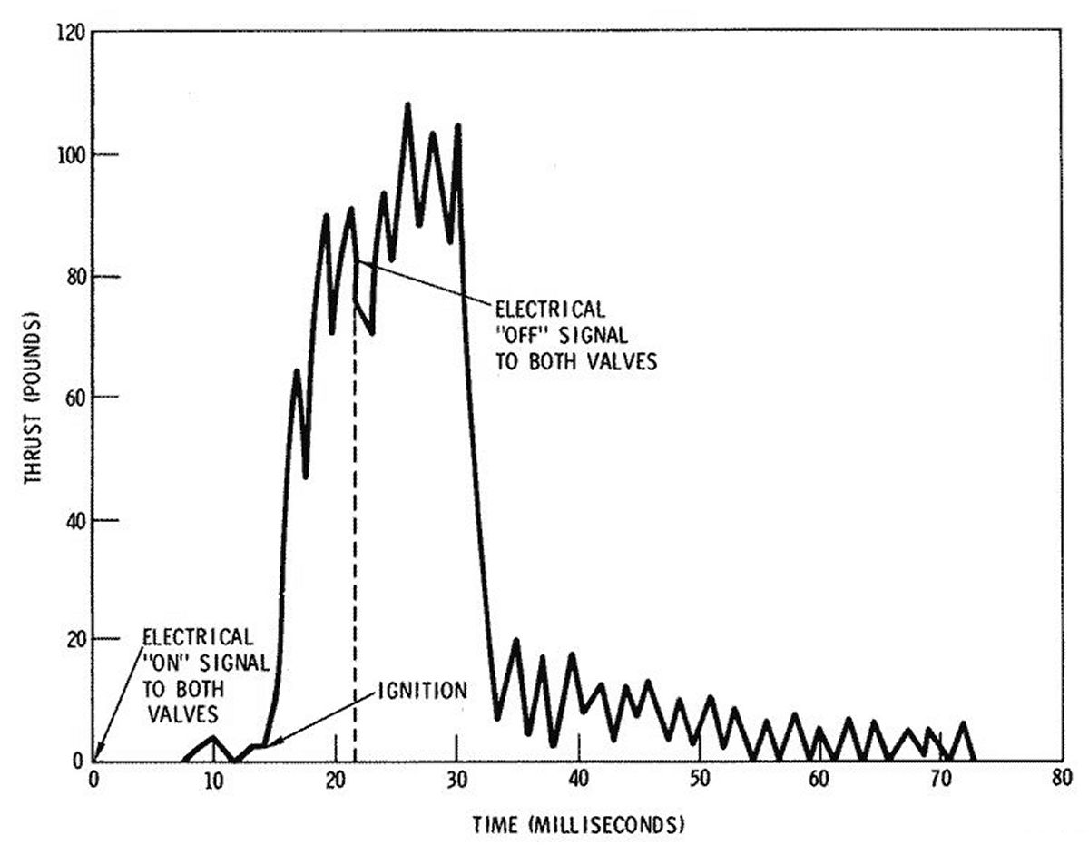 |
| Command Module RCS Engine Control | Command Module RCS Engine Thrust versus Time |
Propellant Jettison
There were two propellant jettison sequences. One sequence was used in the event of an abort while the vehicle was on the launch pad and through the first 42 seconds of flight. The second was used for all other conditions.
References
Apollo Operations Handbook, Block II Spacecraft Volume 1, Spacecraft Description SM2A-03-BLOCK II-(1) (Houston, Texas: NASA Spacecraft Systems Operation Branch, Flight Crew Support Division, 15 Oct 1969).
Apollo Spacecraft News Reference (Downey, California: Space Division, North American Rockwell, 1969).
--- On to Part 9.30, The Apollo Service Module ---
Send mail to
![]() with questions or comments about this web site.
with questions or comments about this web site.
![]()