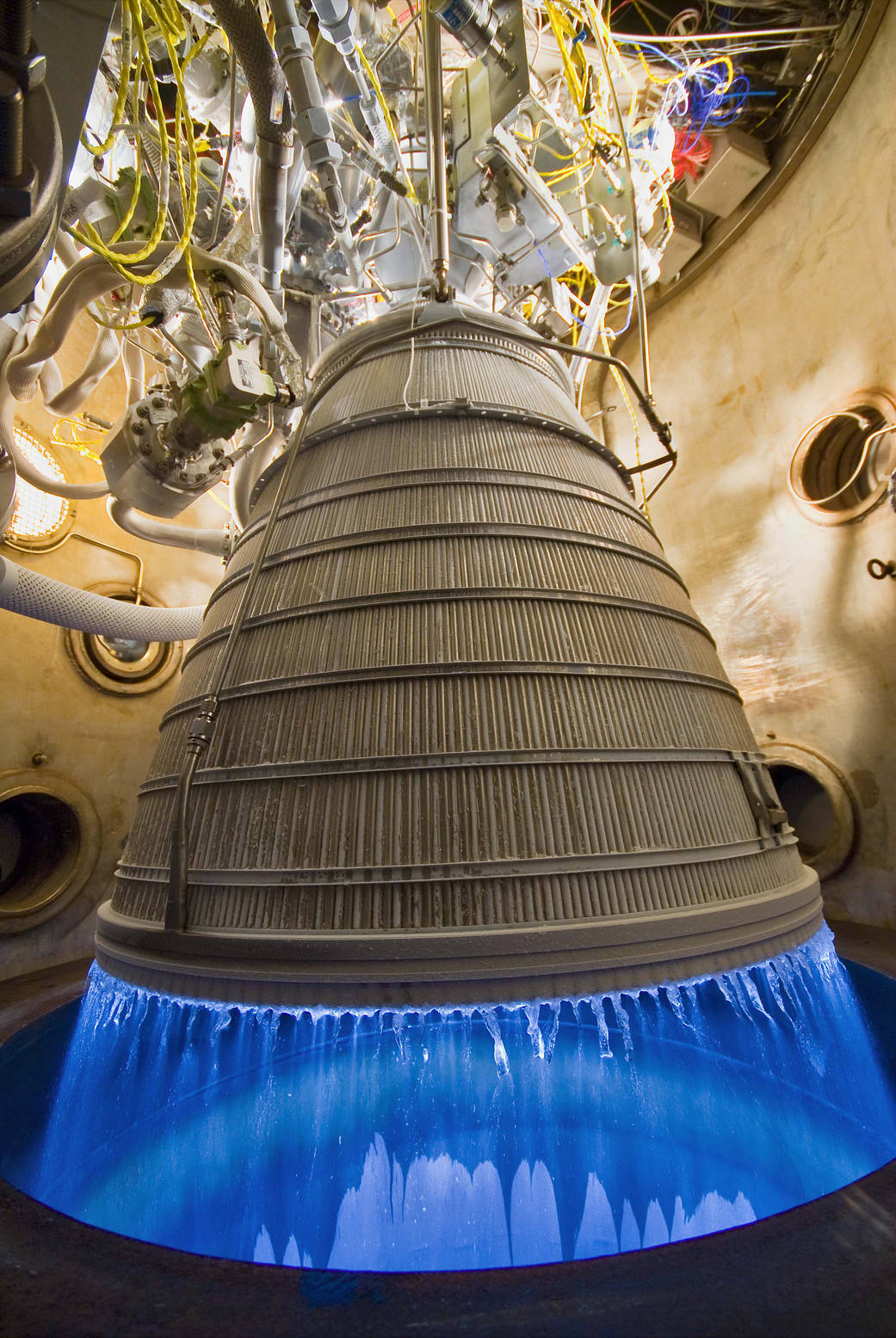
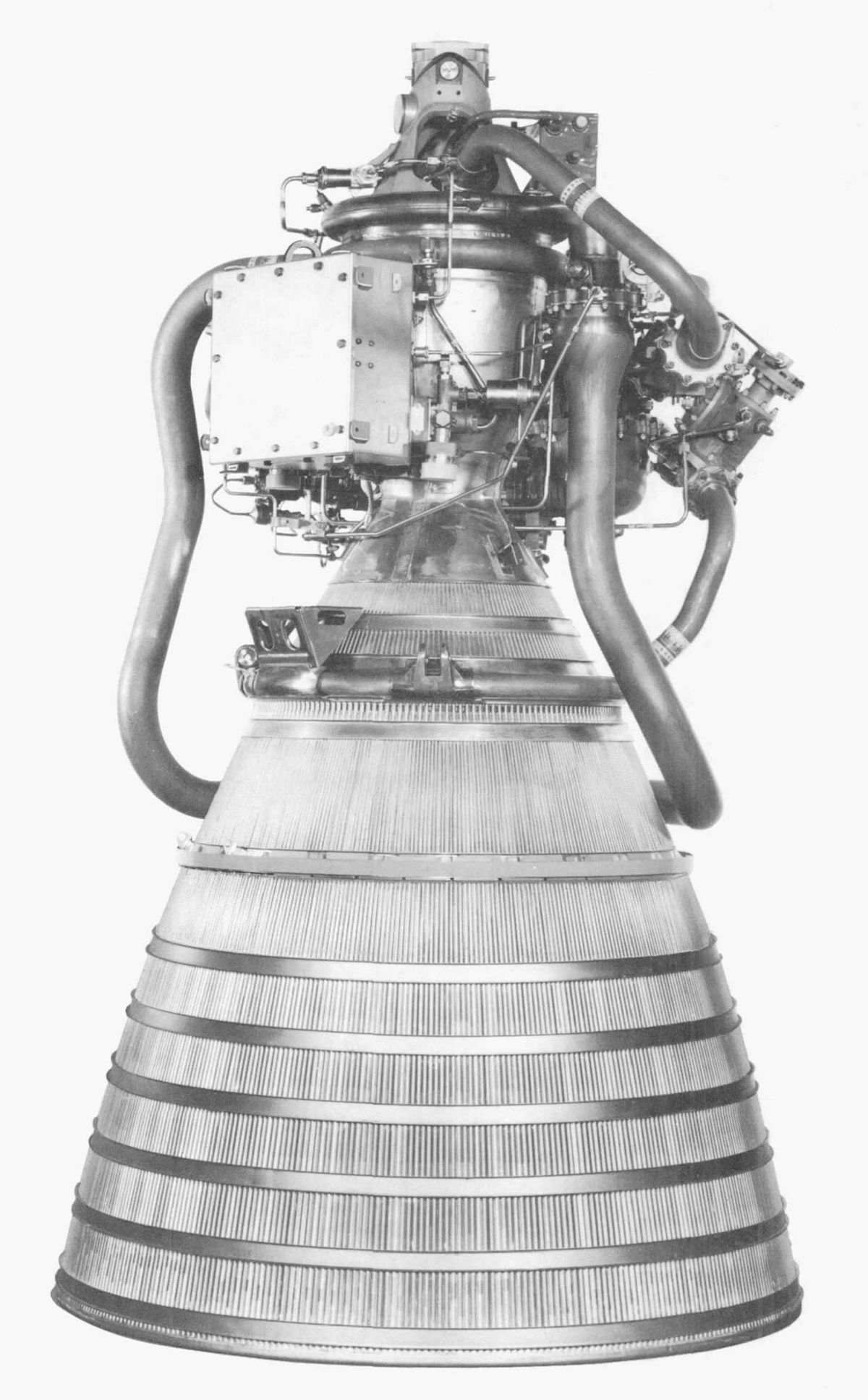
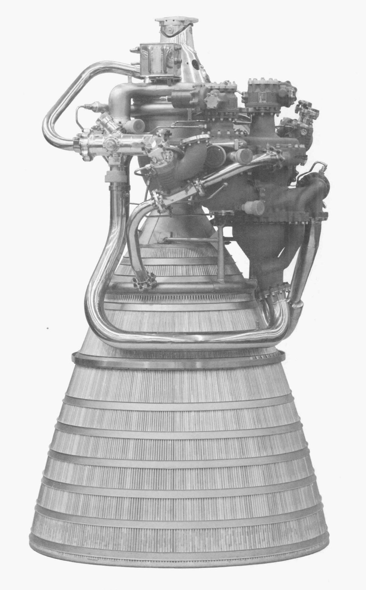
RL10 Under Test
(Pratt & Whitney)
U.S. Manned Rocket Propulsion Evolution
Part 8.21: The Pratt & Whitney RL10 Engine
Compiled by Kimble D. McCutcheon
Published 13 June 2021; Revised 28 Mar 2024
RL10 Under Test (Pratt & Whitney) |
The Pratt & Whitney (P&W) RL10 liquid rocket engine was designed for upper-stage space-vehicles using liquid hydrogen (LH2) and liquid oxygen (LOX) propellants to produce a very high specific impulse. Further performance improvement results from its high expansion ratio and regenerative operating cycle, eliminating the need for a gas generator; this is known as an expander cycle engine. The RL10 is capable multiple starts and can coast in space between engine firings. While the RL10 was never human-qualified during the Saturn-Apollo era, it is fair to say that lessons learned during its development contributed greatly to J-2 development, which was human-rated. At least three technologies pioneered by the RL10 found their ways into the J-2 – Pass-and-a-half fuel flow, the propellant injector configuration, and electric spark ignition. The RL10 first ran in 1959 and is still in production in 2021. It started as a 15,000 lbT engine with an Isp of about 444 sec; today it is rated at nearly 25,000 lbT and an Isp nearing 467 sec. |
Background
Liquid hydrogen was identified as a potential rocket fuel by Tsiolkovskiy, the Russian rocket pioneer, as early as 1903. Later, Goddard, Oberth and Theil also discussed using it. In all cases its disadvantages sent experimenters looking for fuels that were easier to use. LH2 was difficult to produce, transport and store. At -423°F, it presented all kinds of new mechanical challenges to pumps, valves, plumbing, and its extremely low density presented tankage and structural problems. Yet its potential as a powerful and efficient fuel kept experimenters dreaming about it.
By WWII's end American experimenters had successfully produced, pumped and stored small quantities of LH2. They had also begun to create a list of materials that could work with LH2, including bearings that it could lubricate.
In 1956, the U.S. Air Force became interested in high-speed, high-altitude reconnaissance aircraft and created the super-secret Project Suntan to explore these possibilities. Among the technologies studied was the use of LH2 as fuel. Two concentrations of expertise emerged, one headed by Abe Silverstein at the NACA Lewis Research Laboratory and P&W Aircraft, which was proposing a LH2-fueled Model 304 turbojet. NACA Lewis pursued the high science and component development; P&W developed better ways to pump, transport and store LH2. P&W built and tested five Model 304 engines, but Project Suntan was abandoned when Lockheed suggested an even faster titanium airplane that was to become the SR-71.
In early 1958 the Advanced Research Projects Agency directed P&W and the Air Force to develop a rocket engine using Model 304 technology. Two such engines, each rated at 15,000 lbT, were to power the Convair Centaur upper stage; this was the genesis of the RL10 (USAF designation LR115). Although Pratt & Whitney (P&W) had extensive turbojet experience, this was its first rocket engine. NASA Lewis assisted P&W's transition into the rocket world.
Overview
The RL10 combines a regeneratively-cooled thrust chamber with a turbopump-fed propellant flow system. Pumped LH2 vaporizes while cooling the thrust chamber to produce GH2, which expands through a turbine, and drives the propellant pumps that inject LH2 and LOX into the combustion chamber. This is called the expander cycle, which in early development was exclusive to P&W. Pumped LOX is supplied directly to the propellant injector through a propellant utilization (mixture ratio control) valve. LH2 is an attractive fuel because of its excellent heat absorption capacity; in combination with LOX it has high specific impulse.
The quantity of GH2 bypassing the turbine is regulated to control pump output as a function of combustion chamber pressure. A spark igniter recessed in the propellant injector face initiates combustion chamber ignition. Start and cutoff are controlled by pneumatic valves actuated by vehicle-supplied pressurized helium, the flow of which is controlled by electrical signals to solenoid valves.
 |
 |
 |
 |
 |
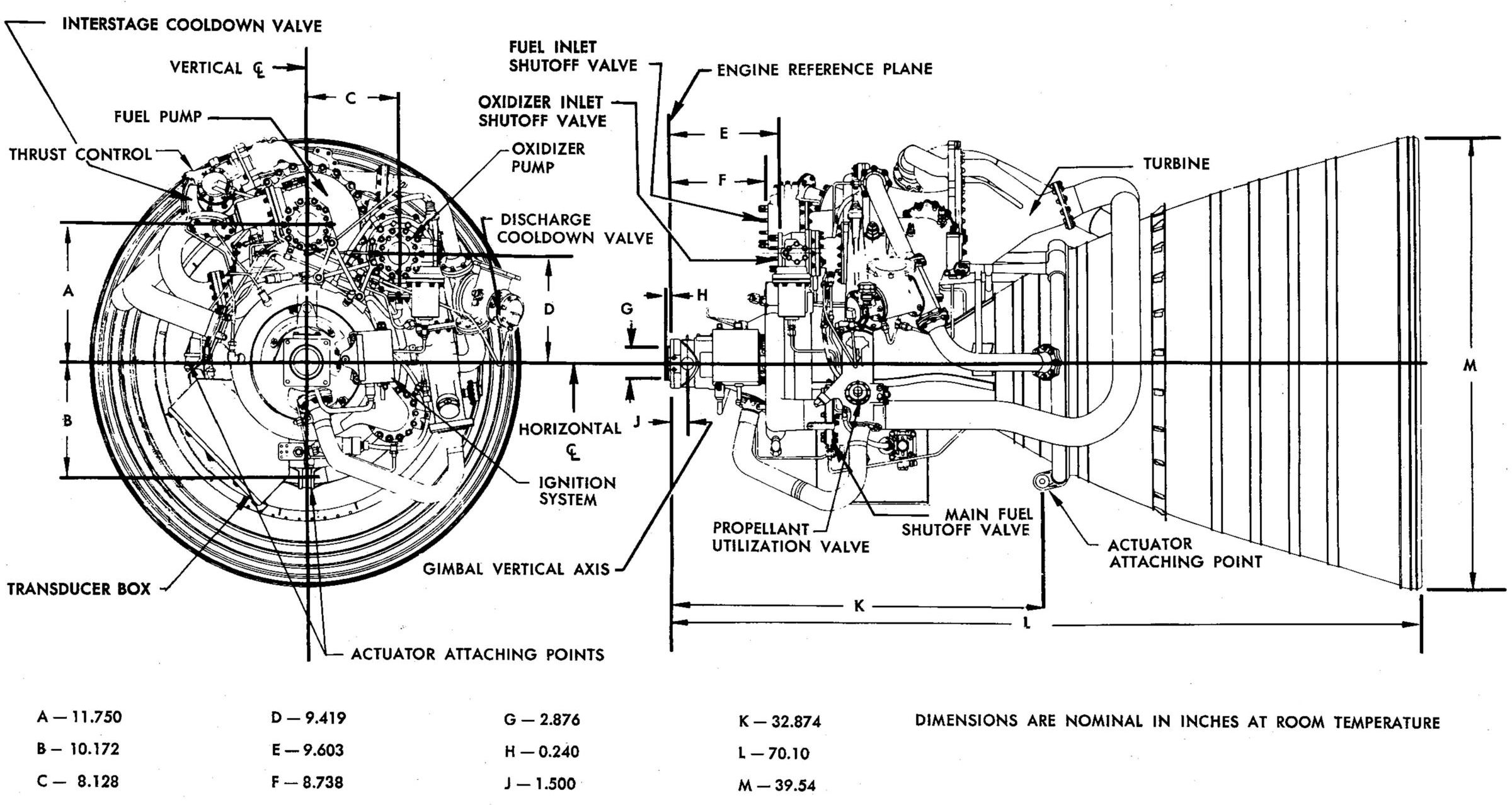
| RL10A-3-3 Installation Drawing |
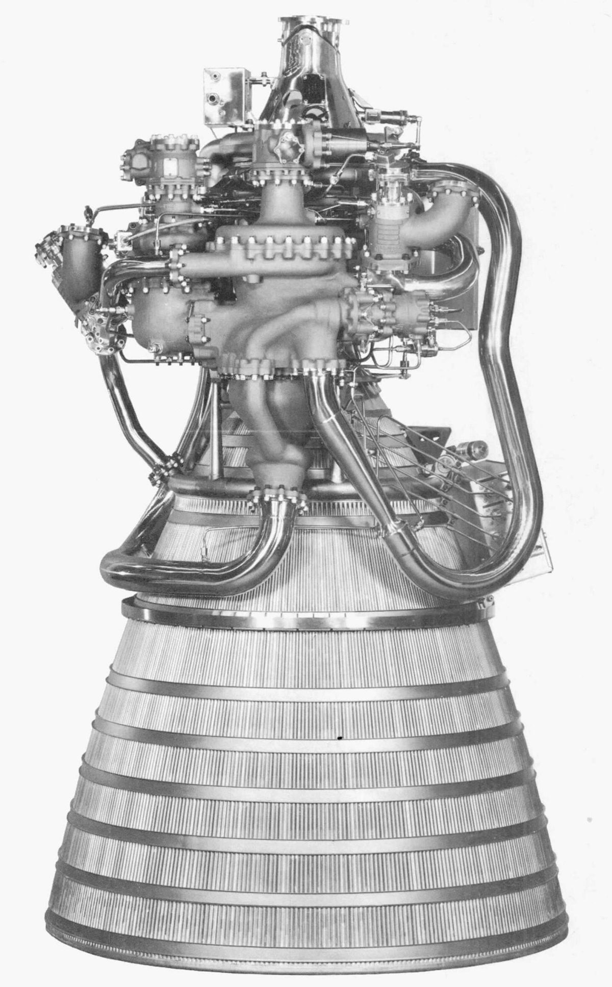
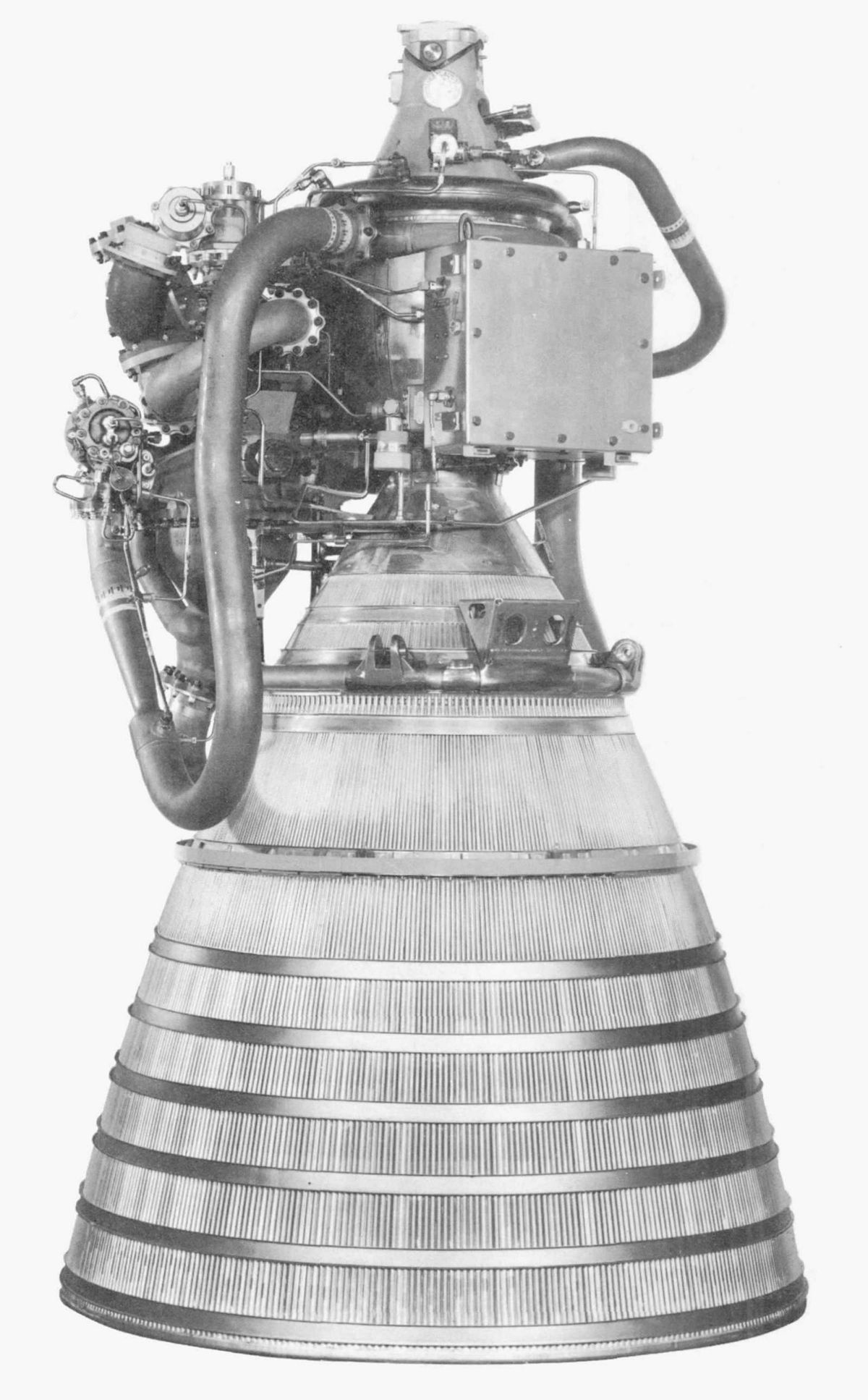
RL10A-3-3 Top | RL10A-3-3 Right | RL10A-3-3 Bottom | RL10A-3-3 Left |
Description
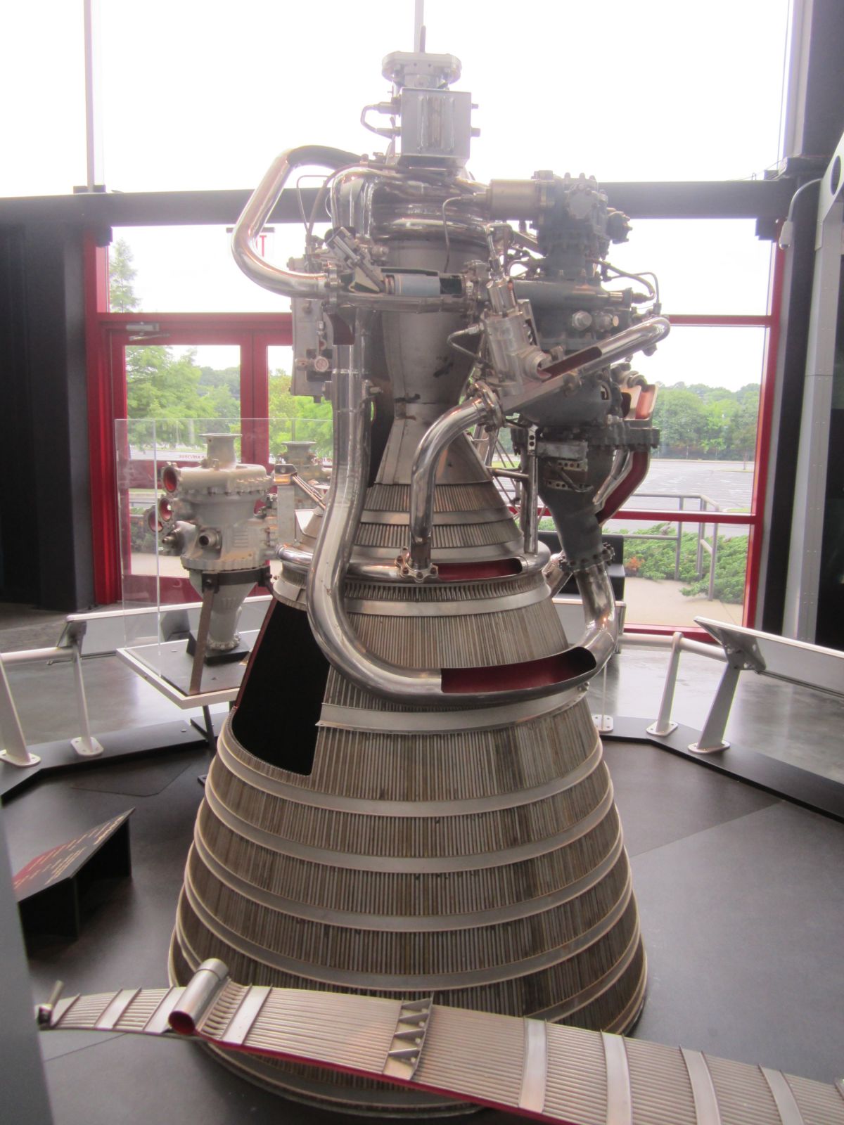
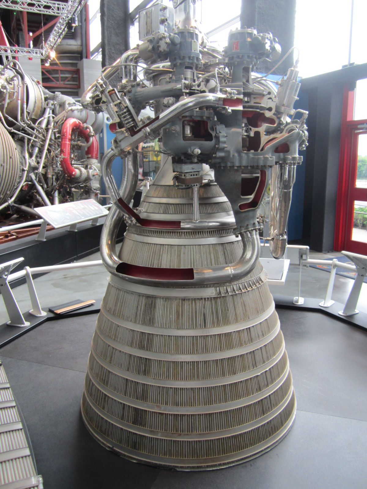
Thrust Chamber
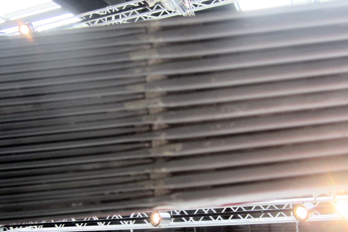
High pressure LH2 from the fuel pump passes through the tubular walls of the thrust chamber, absorbing heat and protecting the tubes from the nearly 6,000°F combustion temperature prior to being expanded through the turbine. The required combustion chamber nozzle contour is obtained through the use of alternate full length and half length double- and single-tapered Type 347 stainless steel tubes with a wall thickness of only 0.012"; the smallest tube diameter is at the nozzle throat. Starting at the injector end, 180 "up" tubes each occupy a 2° chamber wall sector. About quarter-way down the nozzle bell another 180 "down" tubes are interleaved with the "up" tubes, causing each tube to now occupy a 1° nozzle wall sector. All down and up tubes meet at a common manifold at the nozzle exit.
The tapered stainless steel tubes are fabricated by the LeFiell Company using a patented rolling process. P&W receives the straight tapered tubes, which it then fills with wax, bends to the appropriate chamber wall contour, and spanks in book dies to complete the appropriate chamber wall portion. The wax is removed and the flow characteristics of each tube established. In order to achieve the tube-to-tube fit necessary for brazing, each tube is measured at ten stations to an accuracy of 0.0001". A computer program then selects tubes, fitting pimples to dimples and matching flow characteristics in groups of five. The matched set is then scrupulously cleaned and assembled along with inlet and discharge manifolds and stiffening bands on a mandrel under clean-room conditions. The assembled thrust chamber components, along with the assembly mandrels and fixtures, is loaded into a hydrogen-filled retort, and silver-brazed in a gas furnace for 20 hours while being rotated on a spit. This process produces a single light-weight thrust chamber.
 |
 |
 |
 |
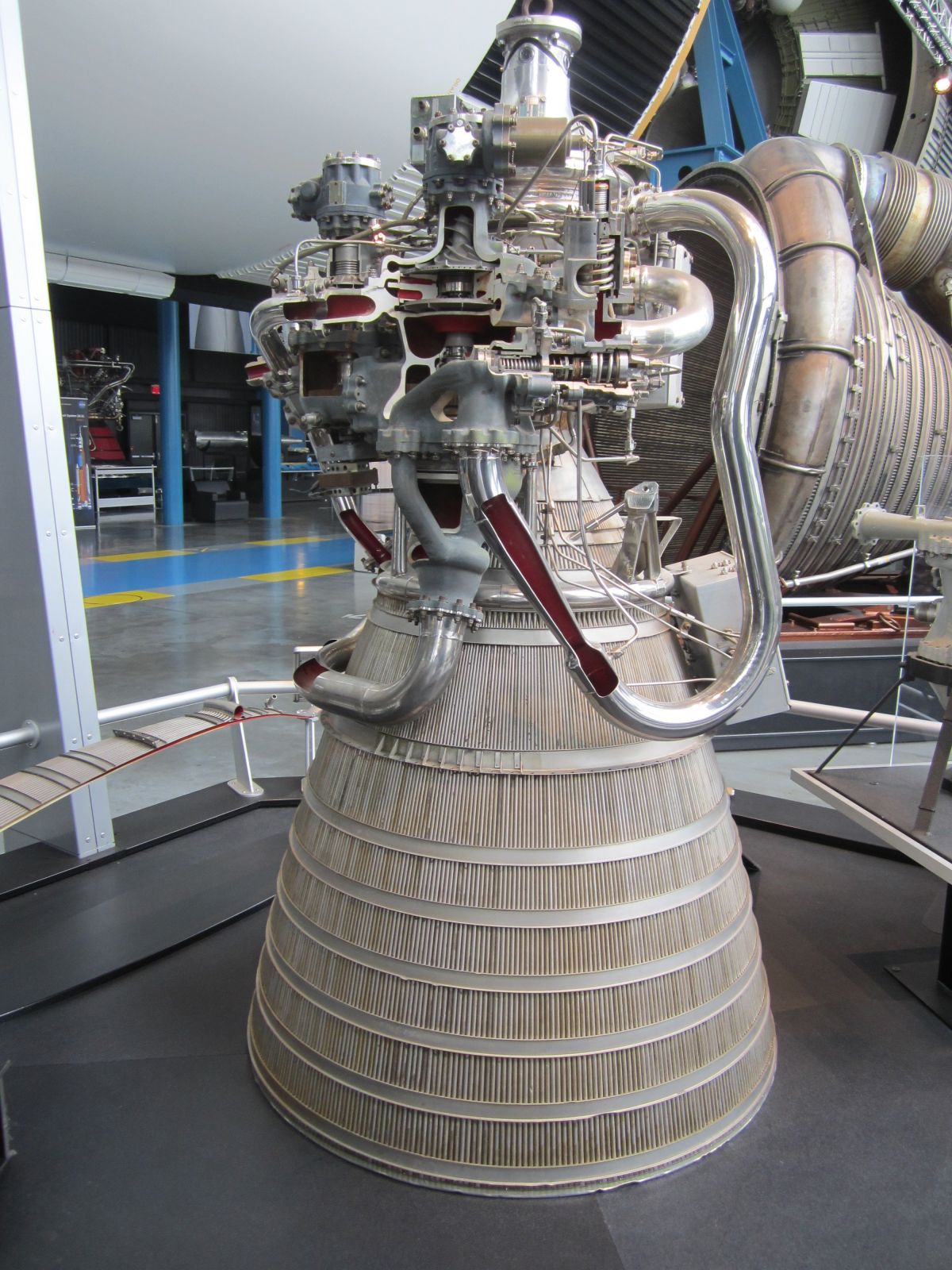
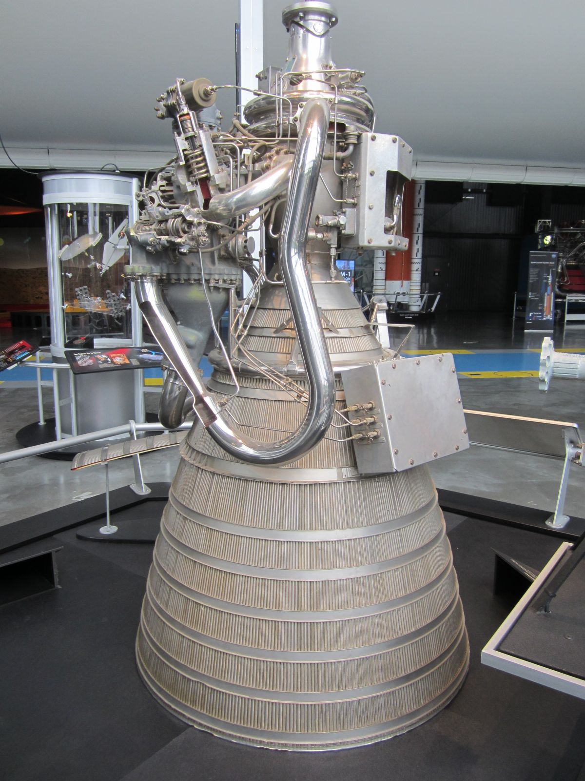
| RL10 Walk Around | |||
 |
 |
 |
 |
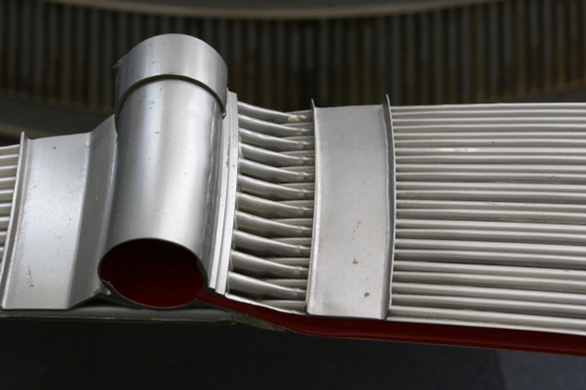
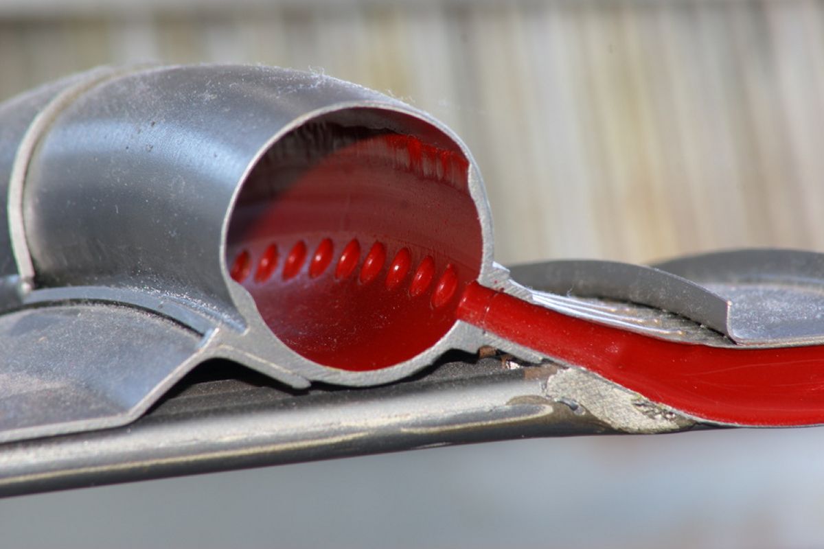
| Thrust Chamber LH2 Inlet Manifold (heriocrelics.org) |
Thrust Chamber LH2 Inlet Manifold (heriocrelics.org) |
Thrust Chamber Inside View of Down Tube / Up Tube Interleave |
Thrust Chamber GH2 Outlet Manifold |
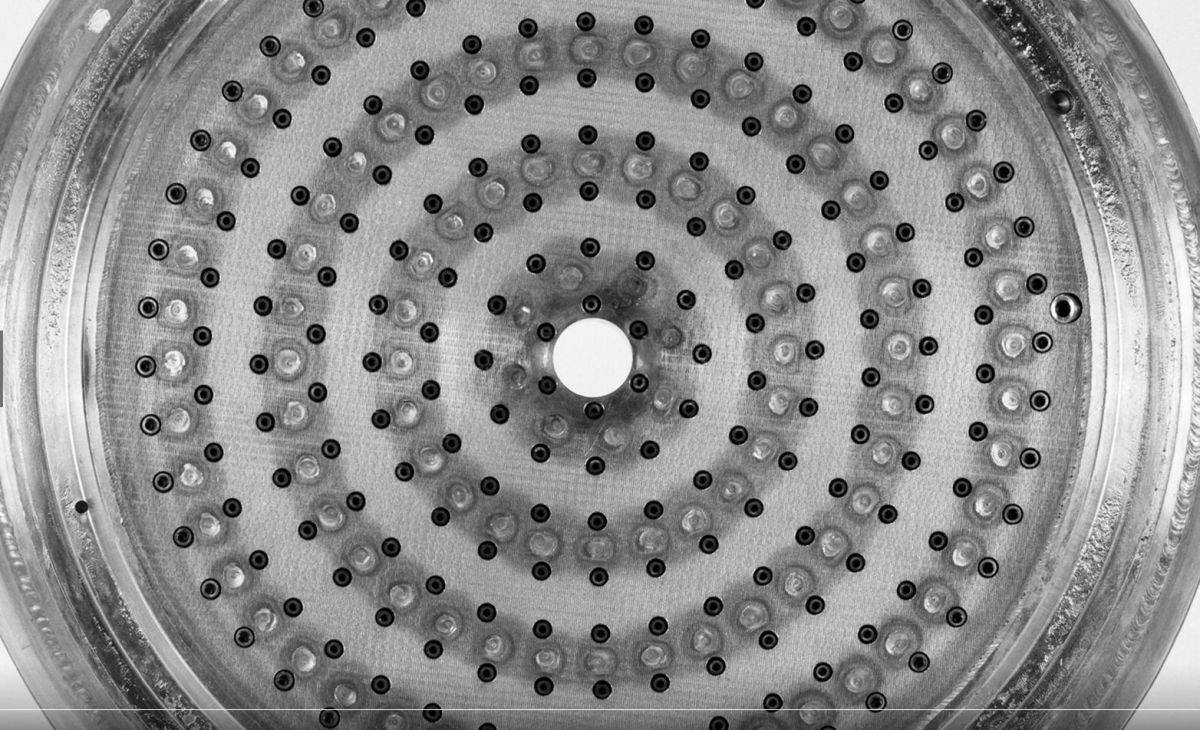 Rigimesh® Injector (heriocrelics.org) |
The propellant injector consists of injector elements protruding through a porous plate. The injector elements are concentric jets with a central LOX stream surrounded by an annular GH2 stream. This design atomizes and promotes propellant mixing to provide the correct conditions for ignition and efficient combustion. This scheme was invented by Abe Sliverstein's team at the NACA Lewis (now NASA Glenn) Research Center during its work on hydrogen combustion for Project Suntan. The NACA injector had a sheet metal aft plate that was cooled by GH2 on its front side. This plate warped with repeated engine runs. P&W eliminated this distortion by substituting "Rigimesh®", a material formed by hot-rolling stacks of Type 347 stainless steel mesh together to form a porous sintered plate that was cooled by GH2 flowing through it.
The LOX and GH2 orifices are supplied from two separate chambers formed by the assembly of three mutually-supporting conical plates. LOX is supplied to the forward chamber through a central manifold, and GH2 is supplied to the aft chamber by an external manifold. Machined tubes projecting from the center plate form the oxidizer orifices and extend through holes in the aft plate, thus forming annular fuel orifices. The injector contains 216 injector elements arranged in equally-spaced concentric circles.
Turbopump
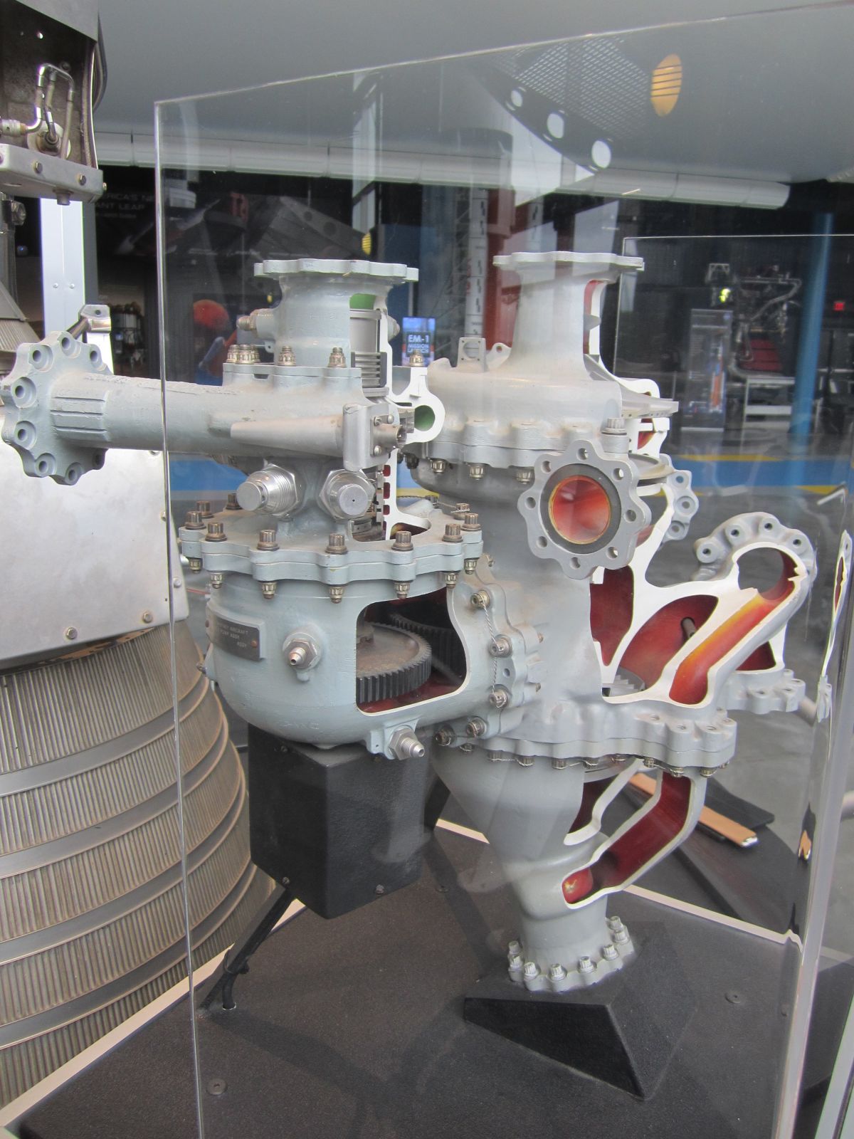
The two-stage centrifugal fuel pump features back-shrouded impellers, volute collectors, and tangential diffusers. The first-stage impeller consists of 22.5° spirally-swept vanes. The second stage impeller is a radial vane type. The two stages are mounted back-to-back to minimize thrust unbalance. The pump first stage incorporates a three-bladed axial flow inducer operating at main impeller speed. Net turbopump shaft thrust loads are minimized by selection of pump impeller and turbine rotor disk areas. The net axial thrust of the fuel pump and turbine shaft assembly is transmitted to the turbopump drive housing through a non-lubricated ball thrust bearing cooled by hydrogen bled from the second stage fuel pump impeller inlet. Each pump stage incorporates a diffusing volute collector and conical diffuser. The inducer, impellers, and pump body are made of aluminum while the pump drive shaft and bearings are of stainless steel.
The oxidizer pump is a single-stage fully-shrouded centrifugal pump driven through a reduction gear train from the fuel pump drive shaft. The shrouded, axial flow inducer has a labyrinth seal on the outside diameter to minimize recirculation. Loads on the non-lubricated ball thrust bearing are minimized by the double shroud design. Pumping vanes on both impeller shrouds reduce the pressure at the labyrinth seal and the carbon face shaft seal.
Three vented compartments, separated by carbon ring seals, prevent oxidizer leakage into the turbopump system fuel side. The center compartment is pressurized with GHe for ground test. The impeller and inducer are made of stainless steel while the housings are machined aluminum. The gear train gears were fabricated from 6260 gear alloy with a molysulfide coating on the teeth.
A full admission, pressure compounded, two-stage turbine producing about 644 hp drives the propellant pumps. Both turbine blade stages, both disks and the hub are machined from a single aluminum alloy forging. Aluminum alloy shrouds are attached by dip brazing.
Cold helium or hydrogen flowing through a prelaunch cool-down check valve partially cools the turbopump before vehicle launch. In the open position, the valve allows liquid helium or hydrogen from a test stand or vehicle supply at 15-40 psig to flow into the first stage fuel pump and fuel pump shaft seal cavity. The helium or hydrogen is then discharged overboard through the gearbox relief vent and fuel bleed-cool-down valves. When helium or hydrogen pressure is removed, a spring closes the check valve, which is held closed by fuel pump discharge pressure as the engine accelerates.
 |
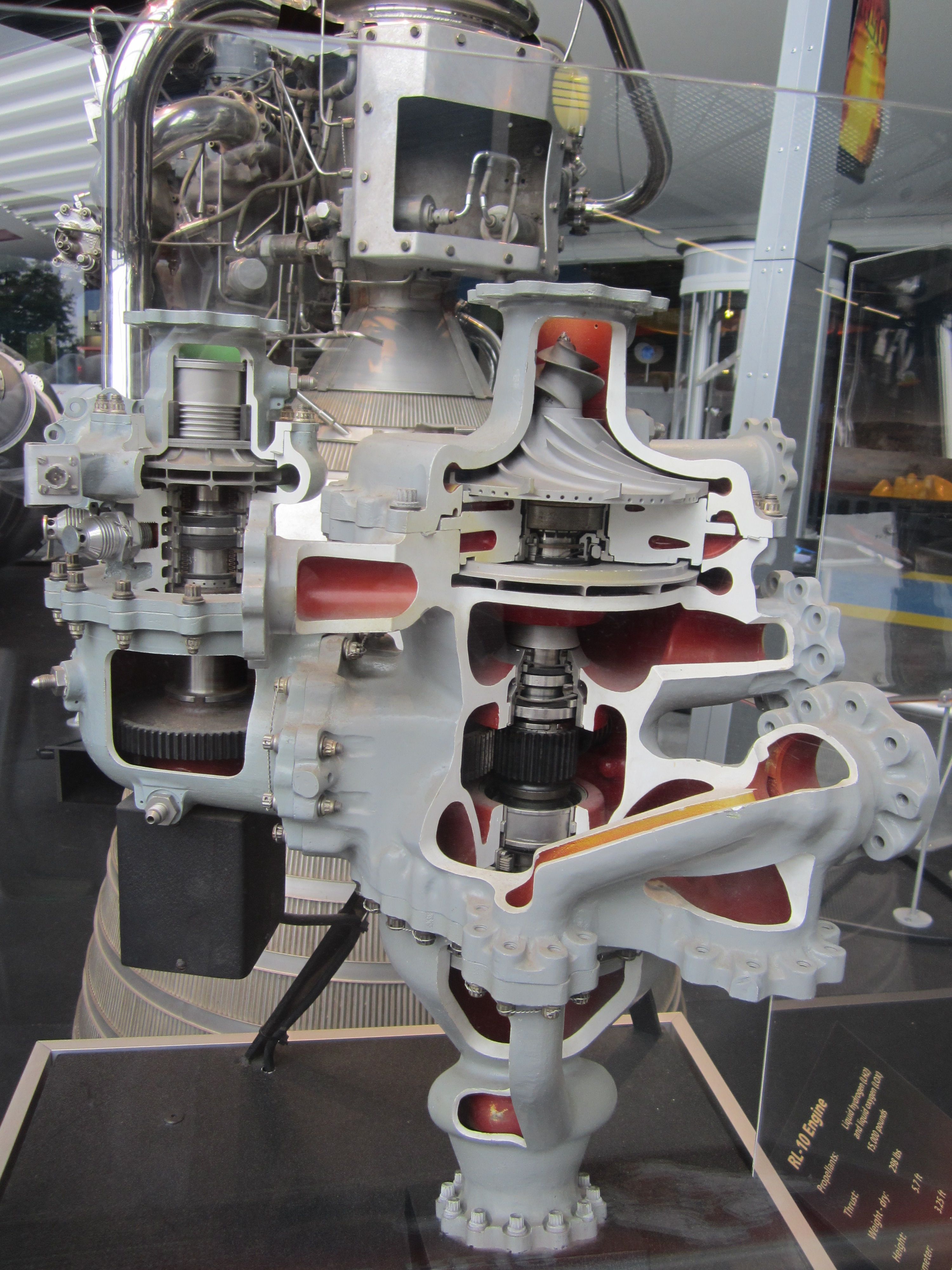 |
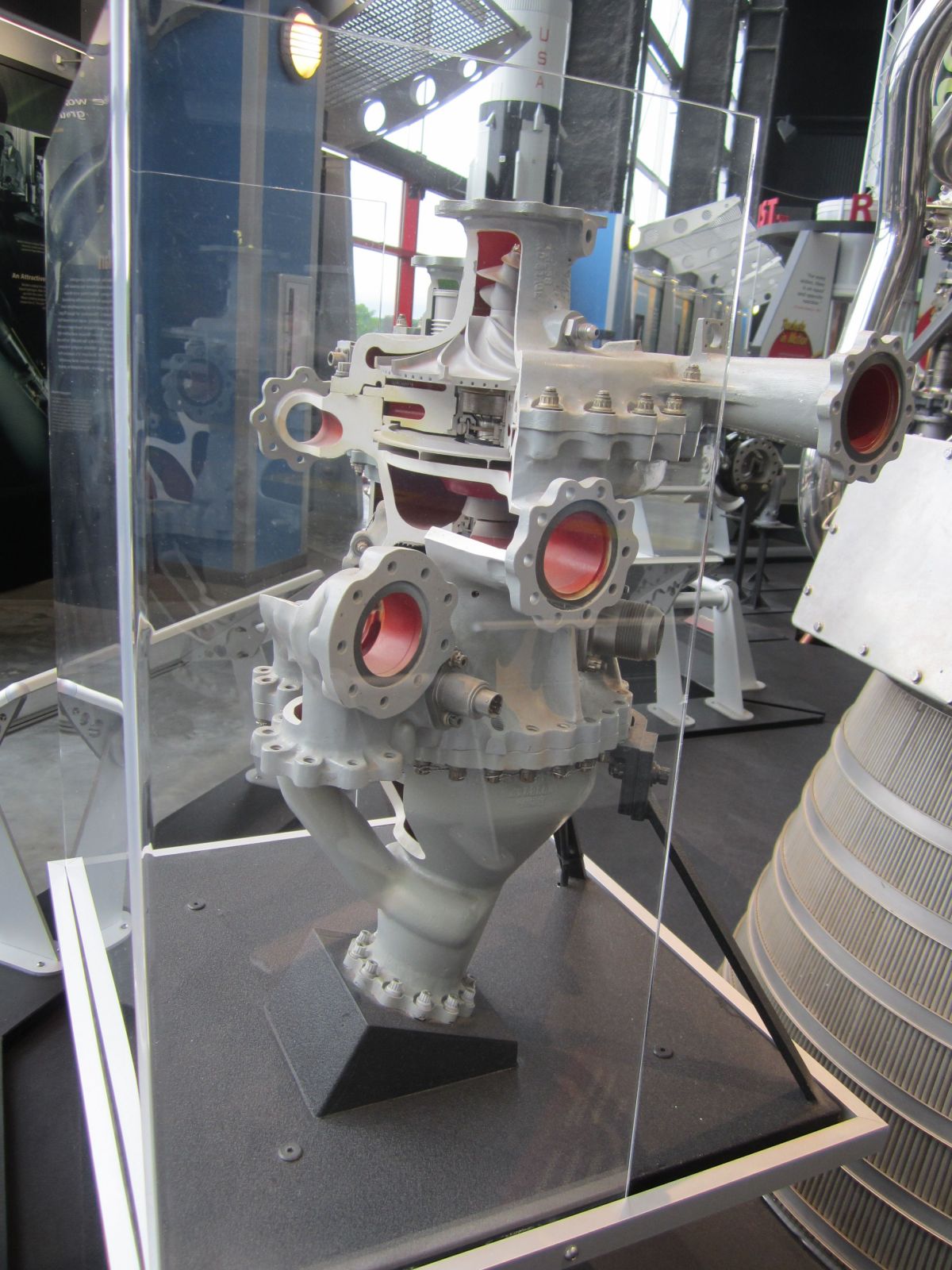 |
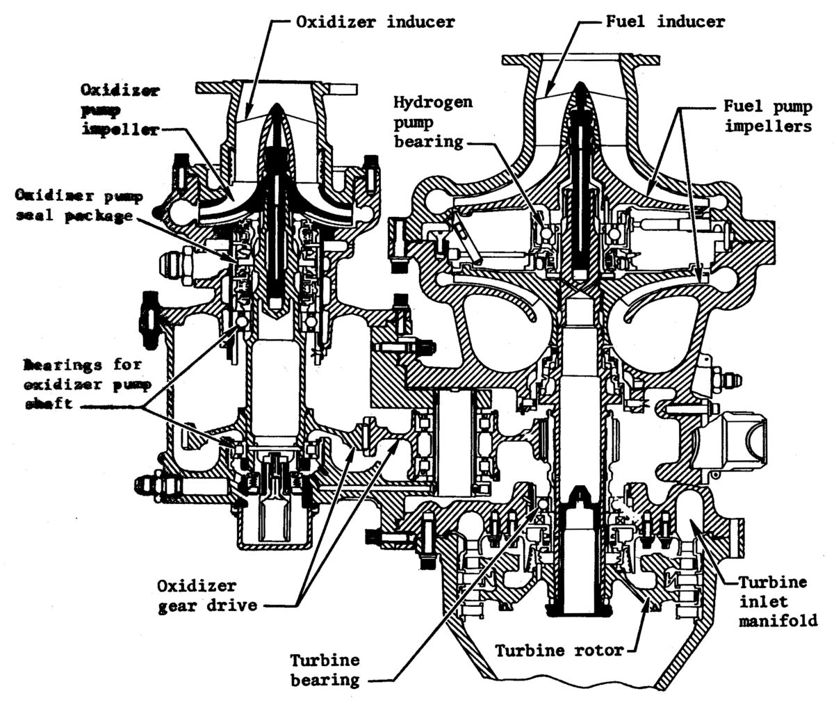 |
| LOX Side | LOX on Left, LH2 and Turbine on Right | LH2 Side | RL10 Turbopump Schematic |
Operation
Propellant Flow Control
RL10 cool-down is initiated by a single prestart solenoid serving both fuel and oxidizer. This prestart solenoid valve remains open until engine cutoff. Helium pressure resulting from prestart solenoid valve opening actuates the propellant inlet valves allowing the propellant to flow through the supply system, thus lowering the temperature of these parts to operating conditions. During the prestart phase, LOX flows through the oxidizer pump, the propellant injector, and overboard through the thrust chamber. LH2 enters the fuel pump, passes through the first stage and enters the interstage connecting tube where a portion of the flow, controlled by the port area of the interstage cool-down valve, is diverted overboard. The remainder flows through the port area of the pump discharge cool-down valve.
The engine start sequence begins when a vehicle electrical signal energizes the start solenoid valve and routes helium pressure to both cool-down valves and to the main fuel shutoff valve. The relative valve timing is controlled by orifices in the helium lines. Helium pressure closes the two cool-down valves. The vehicle energizes the ignition system for a minimum of 1.5 seconds simultaneous with the start signal. During these engine operations, thrust control is achieved by regulating the amount of fuel that is bypassed around the turbine, and consequently, the amount of propellant flow entering the injector. This is accomplished by sensing and responding to the combustion chamber pressure, which is proportional to thrust.
Cutoff signals consists of simultaneous start and prestart solenoid valve electrical supply termination. This removes the helium pressure to all propellant valves by venting all helium-controlled valve actuators overboard, returning the valves to their normal positions. The pump interstage and pump discharge cool-down valves open to full overboard area fuel system lines venting overboard. Fuel system over-pressurization is precluded through the use of fuel boosted cool-down valves; this rapid opening feature ensures that system fuel pressure has decayed prior to the closing of the slower acting main fuel shutoff valve. The oxidizer inlet shutoff valve, fuel inlet shutoff valve, and main fuel shutoff valve close, stopping the engine propellant supply, which stops combustion.
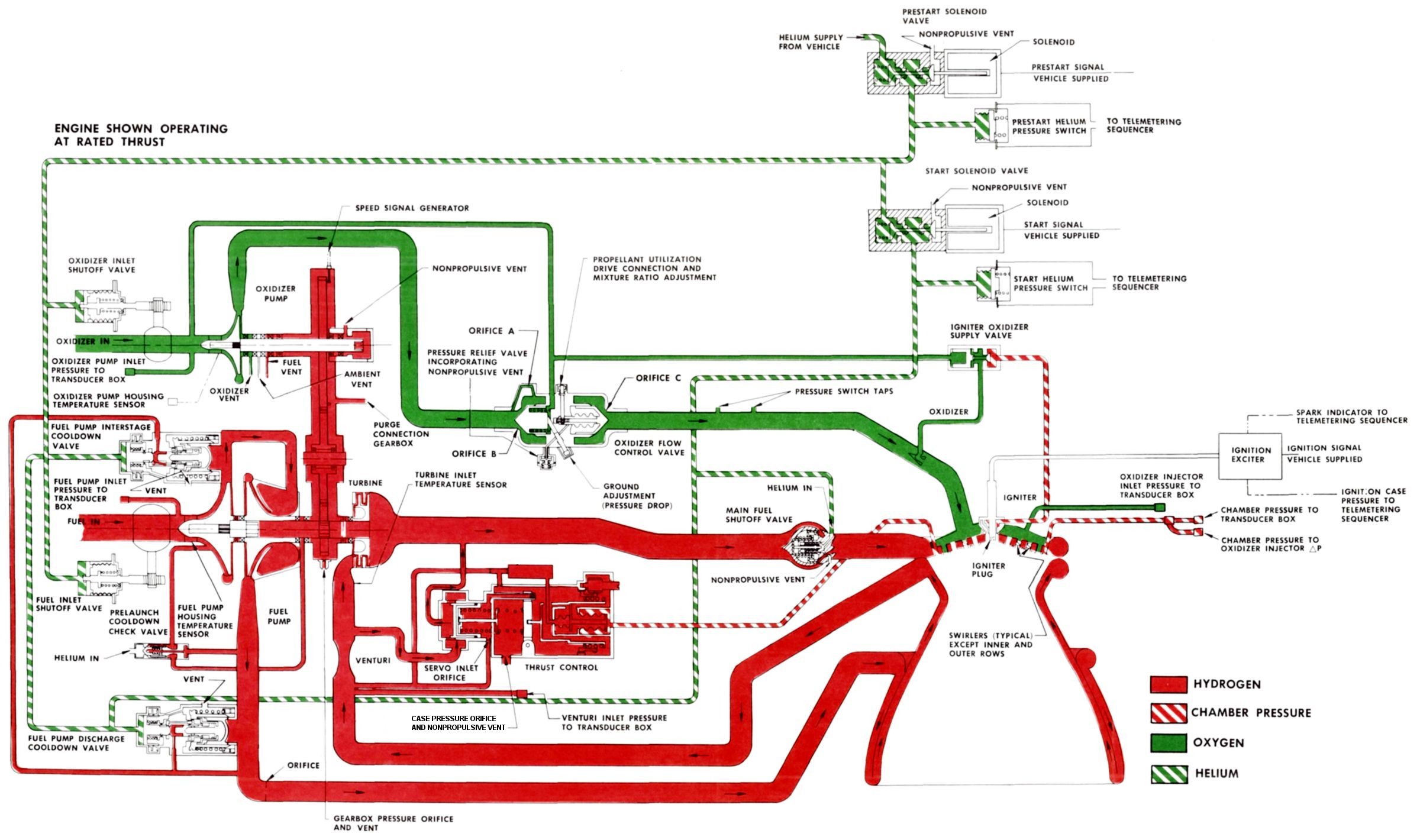 |
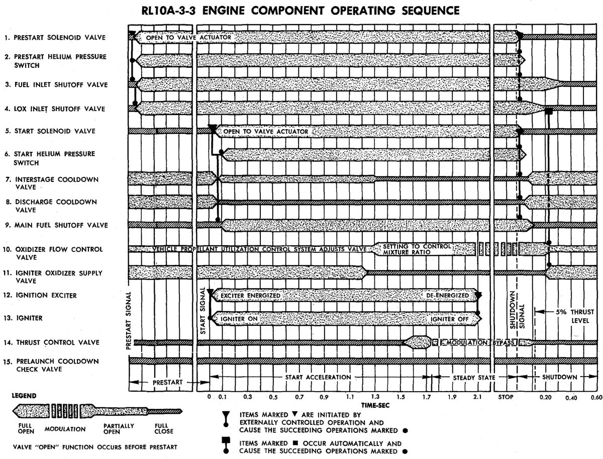 |
| RL10A-3-3 Propellant Flow | RL10A-3-3 Component Operating Sequence |
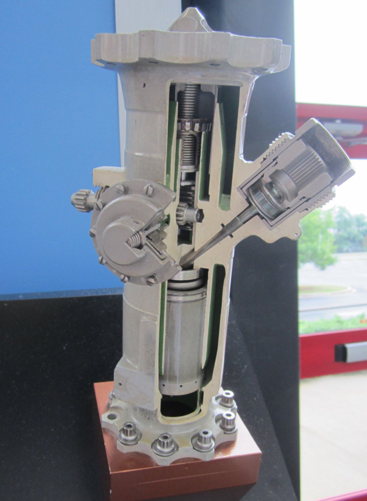
Propellant Control Valves
The fuel pump inlet shutoff valve, fuel pump cool-down valves, the thrust control valve, and the main fuel shutoff valve control RL10 fuel flow. The oxidizer pump inlet shutoff valve, the mixture ratio and propellant utilization valve, and the igniter oxidizer supply valve control oxidizer flow. All propellant control valves except the mixture ratio and propellant utilization valve, igniter oxidizer supply valve, and the thrust control valve are actuated by helium gas pressure controlled by the solenoid-actuated prestart and start valves.
Propellant pump inlet shutoff valves prevent propellant leakage when the engine is not running. These normally-closed helium-actuated ball valves are mounted on the propellant pumps. Spring-loaded resilient plastic seals minimize propellant leakage and bellows-type actuators minimize actuating helium leakage.
The fuel pump cool-down and bleed valves are sleeve-type valves that are spring loaded open to vent the fuel system overboard when the engine is not operating. During the prestart cycle, the pump interstage and discharge cool-down valves are open allowing fuel to flow and cool the pump to operating temperature. Rising fuel pump discharge pressure closes both valves. Removal of helium pressure at cutoff allows both cool-down valves to vent overboard.
The main fuel shutoff valve is a normally-closed, bullet-type valve with a bellows actuator. This valve starts and stops the flow of fuel to the propellant injector. It is opened by helium pressure from the start solenoid valve. Removal of the helium pressure at cutoff allows a positive closure of the valve consistent with the fuel system pressure decay, thus preventing a high pressure surge in the fuel system.
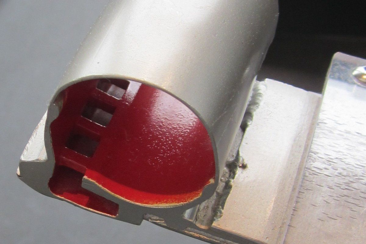
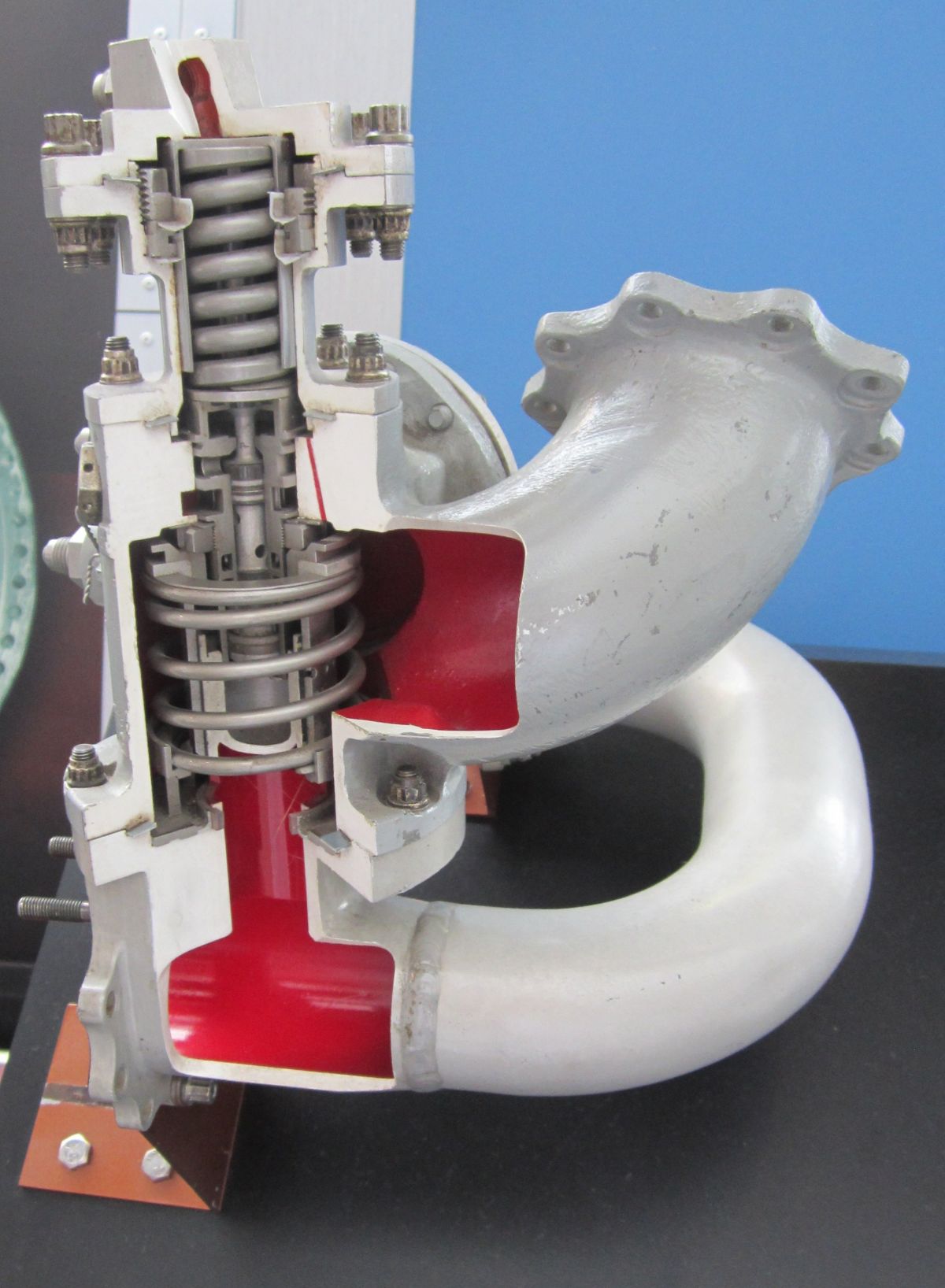
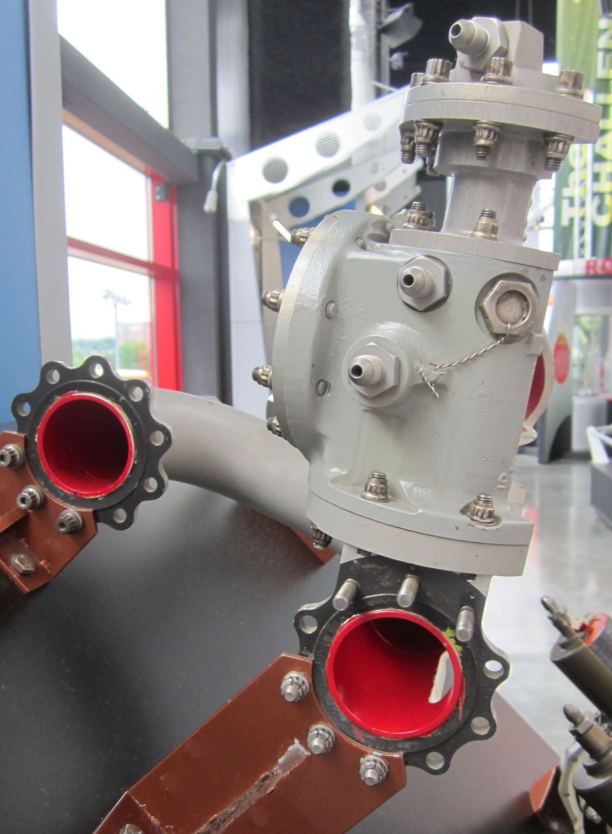
The oxidizer flow control and propellant utilization valve has three orifices that perform three functions. Fixed orifice "A" bypasses oxidizer flow during the prestart phase and the early part of the start cycle. Variable orifice "B" is in parallel with orifice "A" and is spring loaded closed. It opens during engine acceleration as a function of oxidizer pump pressure rise, providing a controlled oxidizer flow and mixture ratio during the engine acceleration. During engine operation, variable orifice "C" can be varied by adjustment shaft rotation, which varies the mixture ratio according to vehicle requirements. The valve has mounting provisions for a drive motor that is controlled by the vehicle propellant utilization system. The adjustment shaft drive pad incorporates stops that control the orifice "C" area; these stops are set during acceptance testing to establish the mixture ratio range.
The igniter oxidizer supply valve assures a combustible mixture at the igniter by admitting gaseous oxygen through drilled passages in the igniter plug housing, which mixes with the gaseous hydrogen already flowing around the igniter. The valve is actuated by the difference between oxidizer pump inlet pressure and oxidizer injector pressure. The valve is open to furnish gaseous oxygen to the igniter during start and is closed during the acceleration when injector pressure becomes higher than pump inlet pressure.
 |
 |
 |
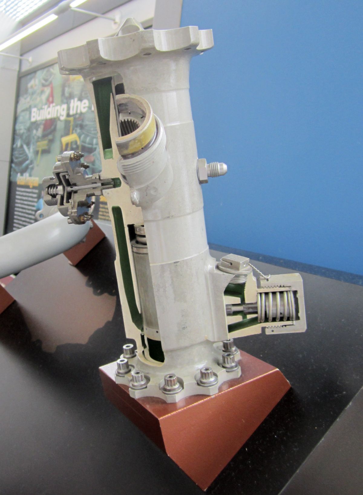 |
| Interstage Cool-Down Valve | Interstage Cool-Down Valve | Propellant Utilization Valve | Propellant Utilization Valve |
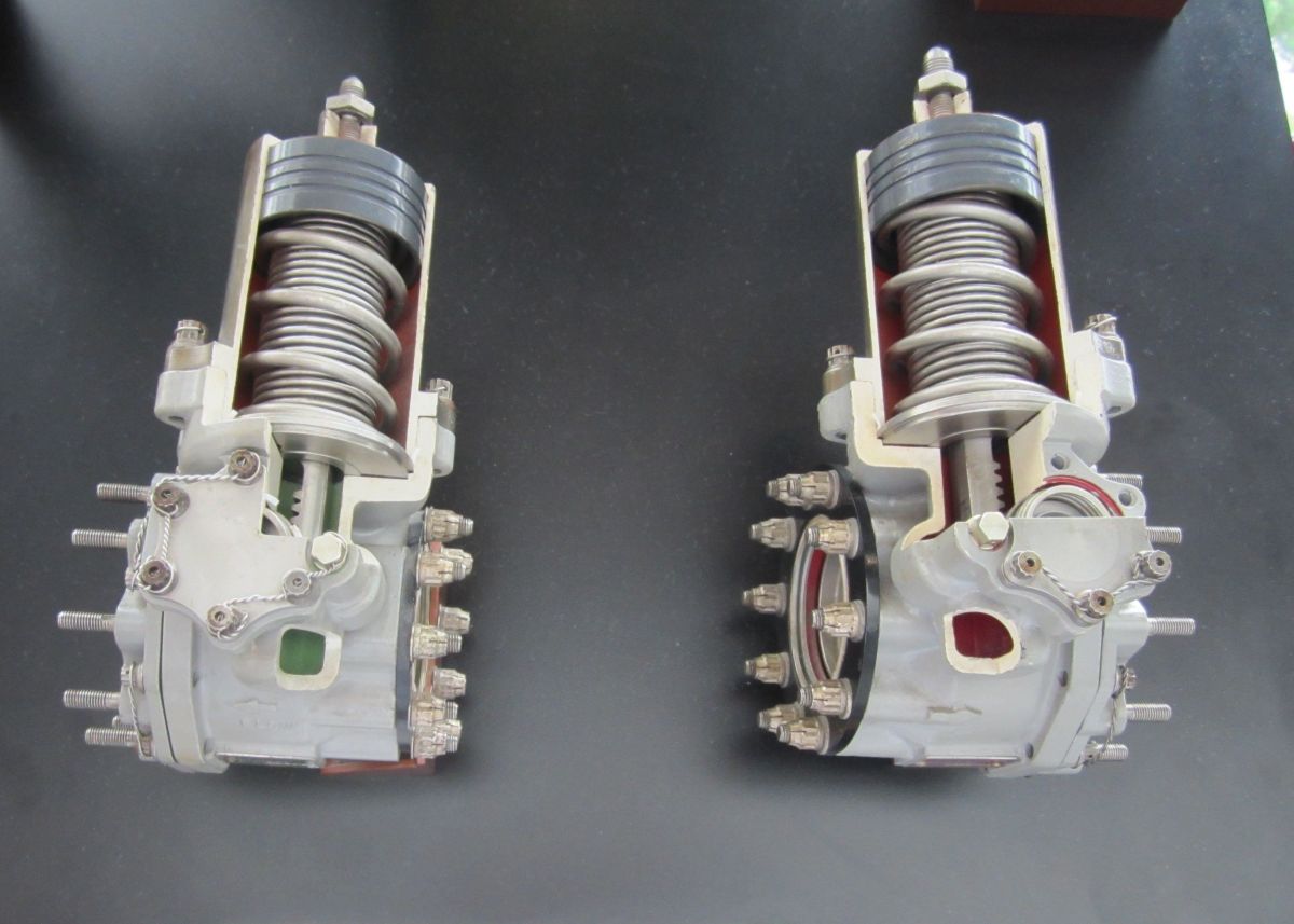
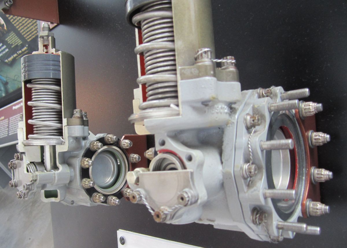
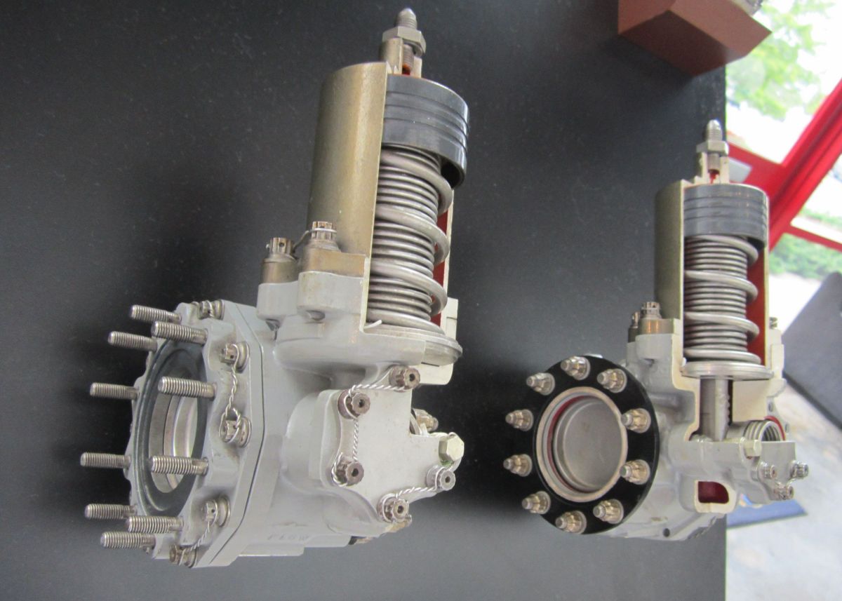 |
 |
 |
 |
 |
| L: Main Oxidizer Valve R: Inlet Shutoff Valve |
L: Main Oxidizer Valve R: Inlet Shutoff Valve |
L: Main Oxidizer Valve R: Inlet Shutoff Valve |
Fuel Tank Pressurization Valve | Solenoid Valve |
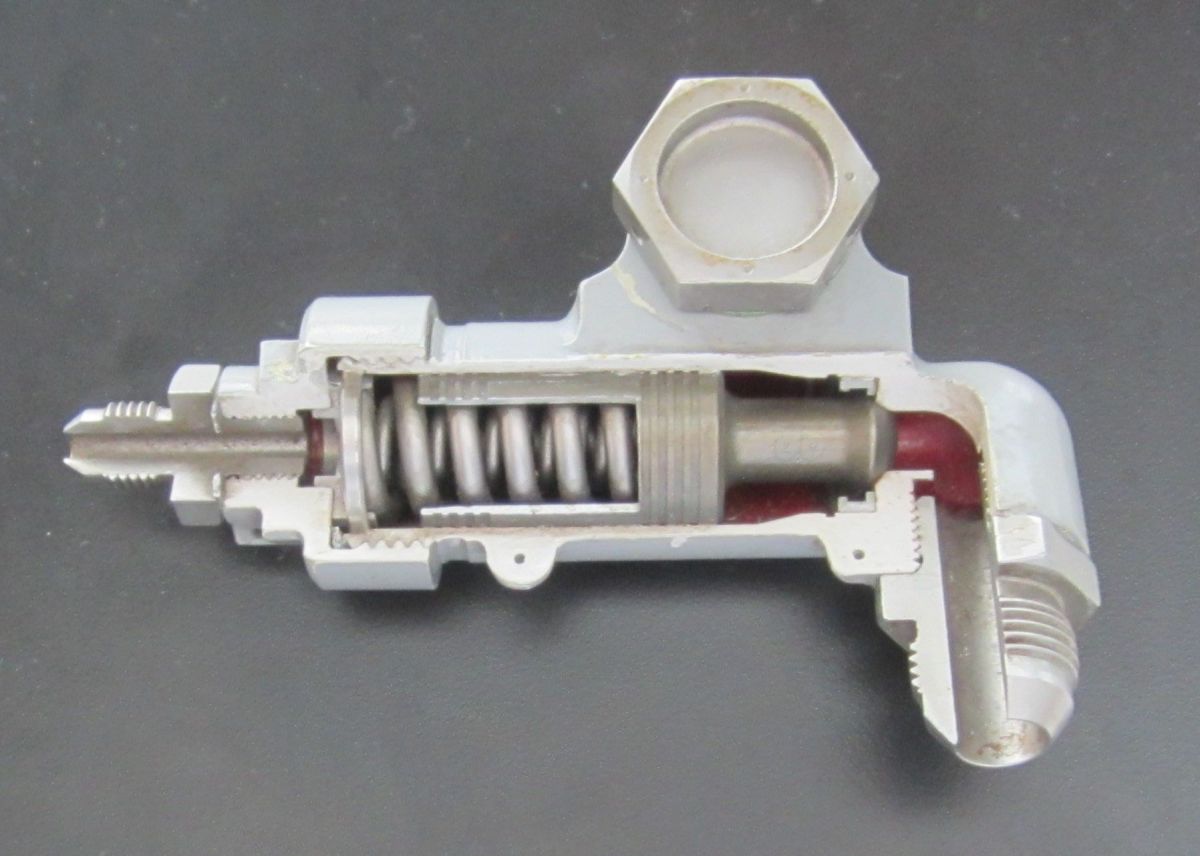
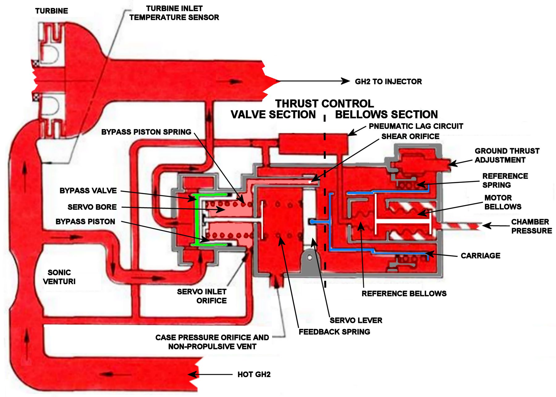
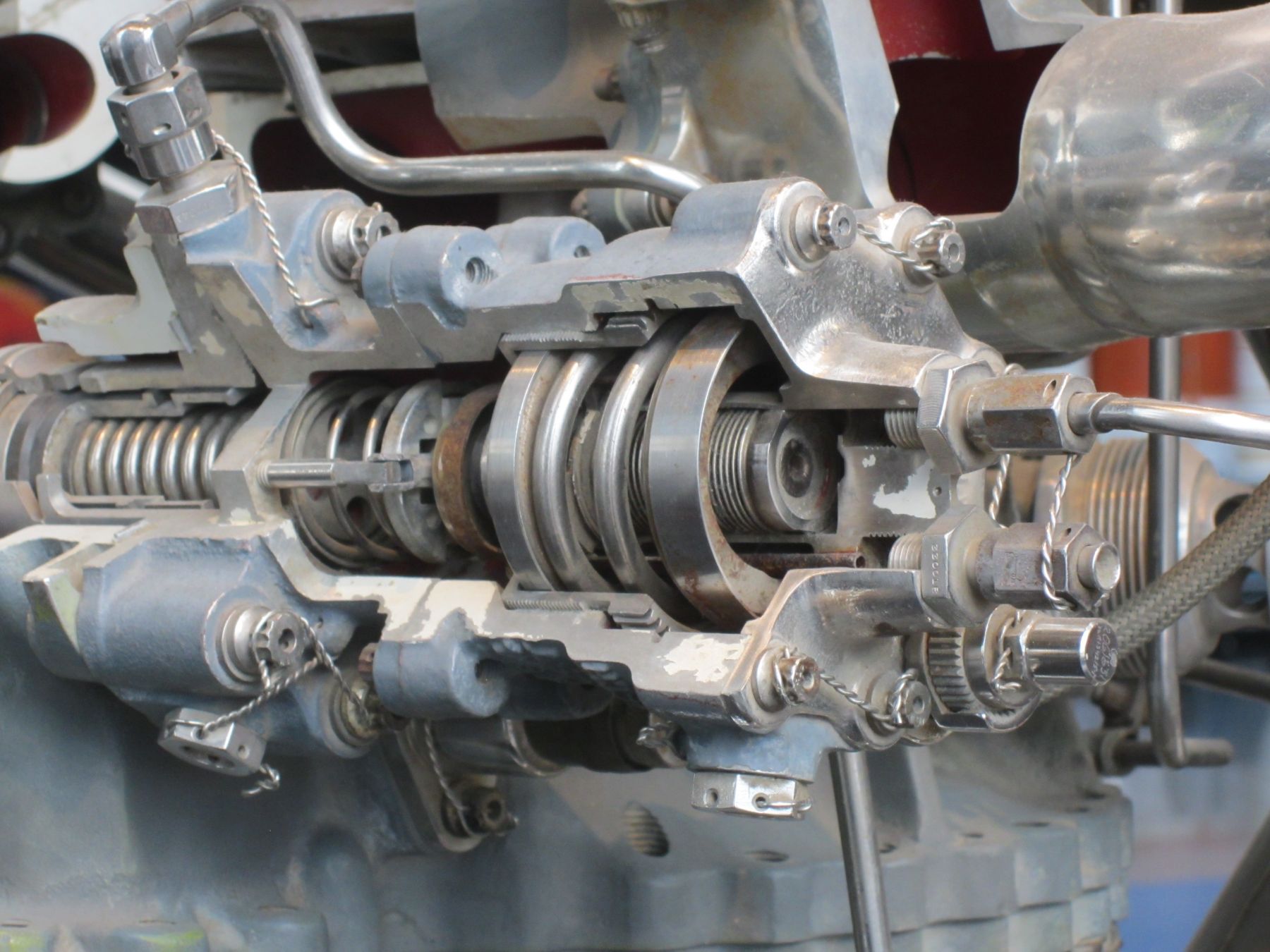
P&W engineers created a clever scheme to ensure stable operation of the thermodynamically sophisticated RL10 engine. Hot GH2 exiting the thrust chamber wall tubes is routed through a sonic venturi whose upstream pressure is a function of its mass flow. This interacts with combustion chamber pressure in the pneumatic/mechanical thrust control, which bypasses some of the hot GH2 around the turbopump turbine. The thrust control employs two separate interacting sections – a thrust control bellows section and a thrust control valve section. A carriage positions the servo lever using combustion chamber pressure acting through the motor bellows, reference bellows, the reference spring load, and the feedback spring load. Servo pressure from the venturi upstream side flows through a fixed orifice into the servo bore.
A fork at the servo lever top fits closely on the square shank of a fitting threaded into the servo bore wall. A blind drilling in the fitting admits servo bore pressure to a cross-drilling near the fitting end, which is covered by the servo lever fork. This combination produces a shear orifice that vents pressure from the servo bore in a way that has negligible effect on the force needed for the bellows and springs to move the servo lever. Early versions of this shear valve assembly required extreme skill to assemble and adjust, but as P&Whitney mechanics gained experience, they worked out a fairly rapid assembly and adjustment procedure.
Steady-State Operation – A combustion chamber pressure increase moves the carriage to the left against the reference bellows, reference spring and feedback spring, moving the servo lever to open the shear orifice, which increases the case pressure and decreases the servo bore pressure. A case vent orifice bleeds case pressure to maintain a constant case differential pressure. As the servo bore pressure decreases, the hot GH2 pressure causes the bypass valve piston to move right, compressing the bypass piston spring, increasing the bypass area, and increasing the quantity of hot GH2 bypassing the turbine; this reduces turbine power, lowering pump speed and discharge pressure, decreasing propellant flow, and ultimately reducing combustion chamber pressure to the desired value. The bypass valve travel is transmitted to the servo lever and carriage through the feedback spring, thus balancing the forces on the carriage and returning the servo lever to its normal position.
A combustion chamber pressure decrease causes the carriage to move right, closing the sheer valve orifice. servo bore pressure then increases and the resulting force differential moves the bypass valve piston left, decreasing the bypass area, which increases turbine flow, turbine power, pump speed, discharge pressure and ultimately, combustion chamber pressure to the preset value.
Start Operation – Making a rocket engine controller that works well during steady-stage conditions is hard enough, but to make this same controller behave during start and stop transients is true genius. Before the RL10 starts, pressure throughout the thrust control and engine is zero (it is a vacuum engine, intended for exoatmospheric use). The bypass valve is fully closed by the bypass piston spring and both the reference bellows and motor bellows are fully extended by the reference spring. The closed bypass valve position results in minimal bypass and maximum turbine power for a rapid start transient. The bypass valve remains closed until hot GH2 pressure acting against the bypass piston compresses the bypass piston spring, causing the bypass valve to open, limiting engine thrust overshoot. Servo bore pressure is initially vented into the case due to the open shear orifice position. As combustion chamber pressure rises, so does the servo bore pressure, which is supplied from the venturi upstream side.
Thrust control case pressure rises slowly due to restrictions in the lines delivering hot GH2 from the venturi upstream side. The reference bellows is pressurized even more slowly during the engine start transient because of the pneumatic lag circuit in which a coil of small-bore hypodermic tubing restricts the flow of hot GH2. With the reference bellows initially at low pressure and the motor bellows pressurized by combustion chamber pressure, the carriage moves to the left causing the shear orifice to open. It is important that the shear orifice is open during the start transient as combustion chamber pressure rises, venting the servo bore and allowing the bypass piston to move right and the bypass valve to limit thrust overshoot.
As the start transient continues, the reference bellows is slowly pressurized through its lag circuit. This slow pressurization causes the carriage to move to a position that partially closes the shear orifice, additionally pressurizing the servo bore, which causes the bypass valve to assume the position required to establish the appropriate combustion chamber pressure. The final thrust control carrier position, and thus the shear orifice position, is set by the reference spring acting against the motor bellows. This spring can be set remotely during engine ground testing to bring the engine to its rated thrust.
There is a fixed bypass area in addition to the area controlled by the bypass valve position. This limits engine thrust if combustion chamber pressure to the control is lost.
The RL10 thrust control is a marvel of ingenuity and construction. After its initial assembly and adjustment hurdles were overcome, it has performed well for over 60 years. P&W has considered replacing it with a fully electronic control, but that would required design, testing and requalification, not to mention worries about electronic component supply chain and obsolescence issues. Looks like the pneumatic/mechanical thrust control is here to stay.
 |
 |
 |
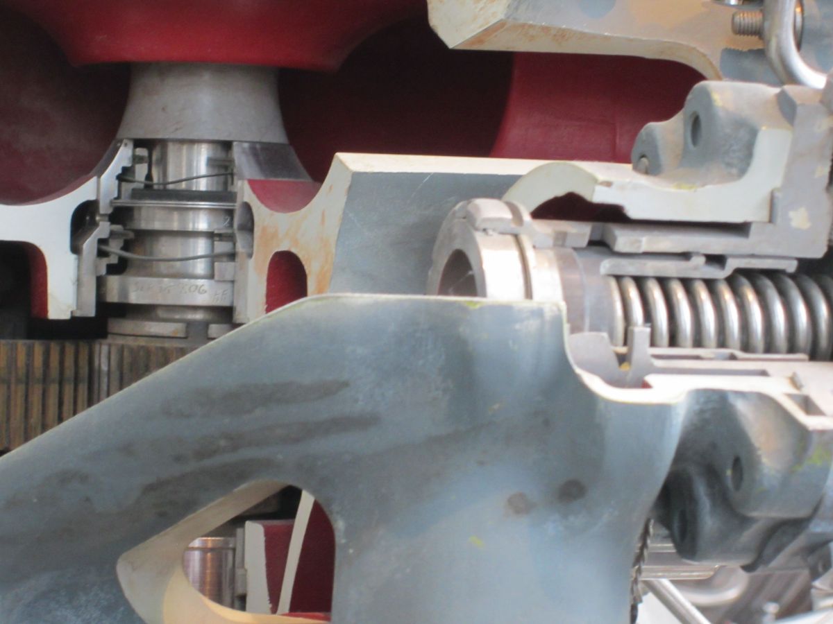 |
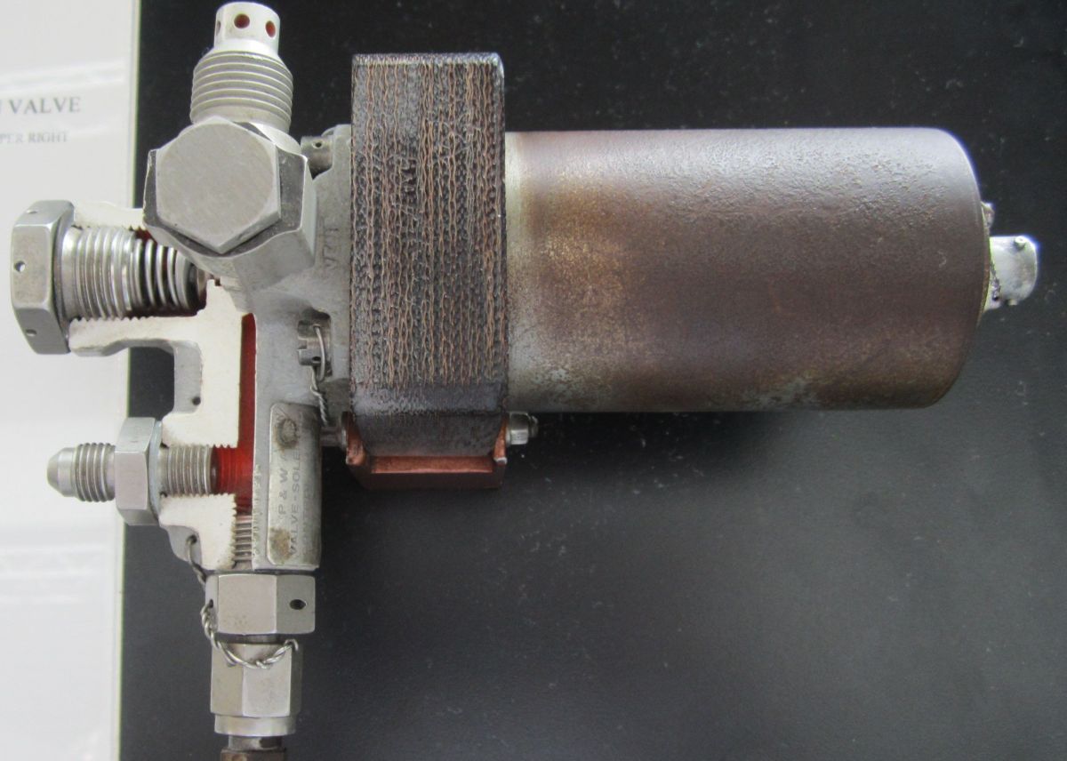
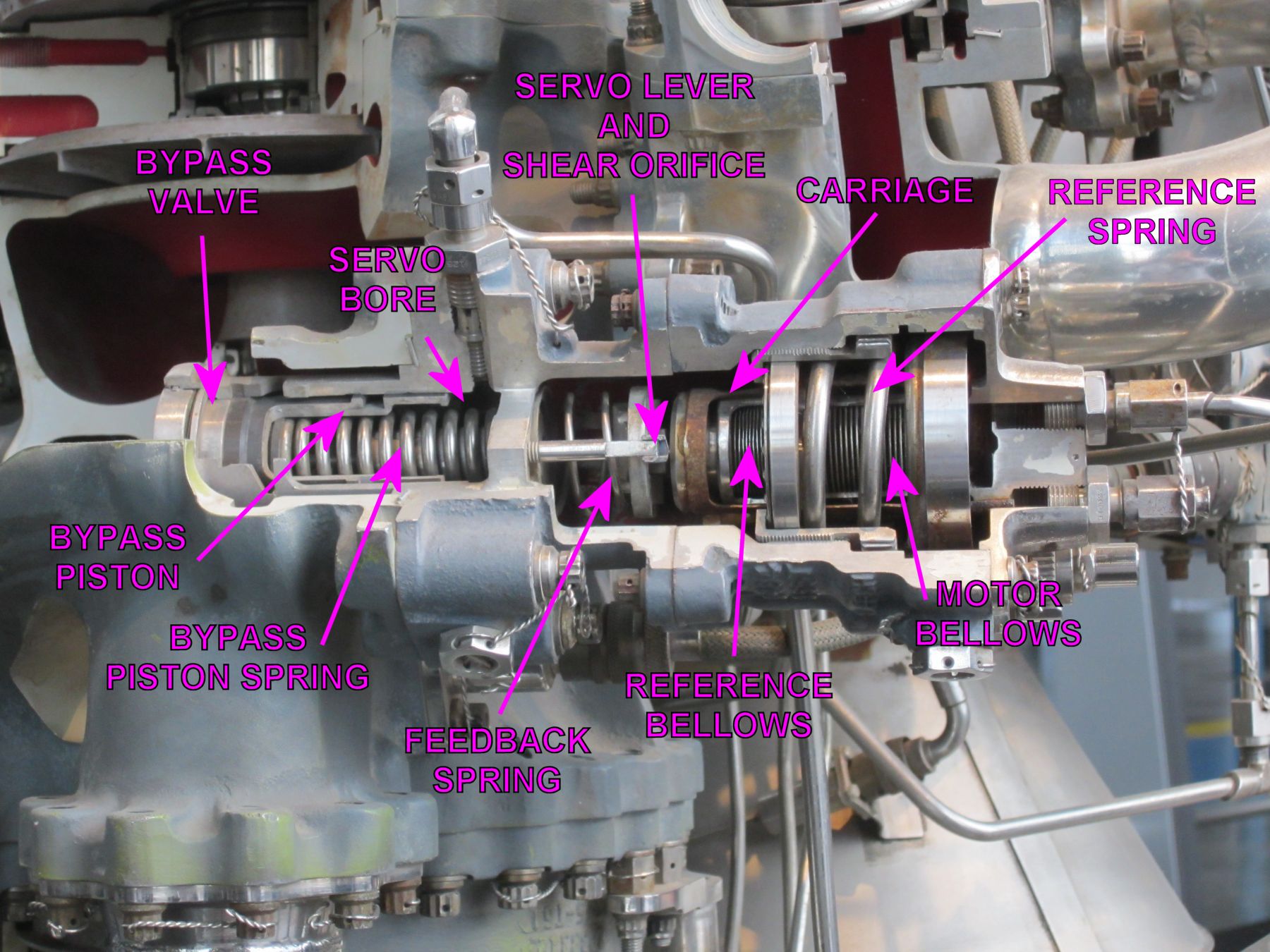
| Schematic | Cutaway | Bellows Section Detail | Valve Section Detail |
Development
By using applied math during the RL10’s design, P&W bypassed much costly hardware experimentation and developed design procedures that became widely used in the rocket engine industry.
Initial engines were assembled with 144/288 tube thrust chambers; this was changed to a 180/360 tube configuration, which improved the turbopump power margin.
Early RL10 plumbing used braid-covered flexible joints to accommodate vibration and expansion; these were changed to solid ducts, which were long and flexible enough provided special seals and assembly techniques were employed. The seal was a Teflon-coated conical washer that was captured in an angular cavity machined into the flanges. By tightening the flange fasteners in small increments, a hydrogen gas tight assembly was assured. Trouble was, when MSFC got the engines, they tore them down for inspection and put them back together without replacing the use-once seals, creating leaks. P&W ultimately convinced NASA to leave the already-inspected engines alone.
P&W selected Waspaloy® (a P&W-proprietary gas turbine blade alloy) as the turbopump gear material. When the engine was run gear teeth sometimes welded themselves together; the H2 environment was cleaning the teeth so well the metal surfaces fused. A change to a conventional SAE 6260 alloy that had been carburized and treated with a dry molybdenum sulfide coating solved the problem.
P&W had to develop a special cool-down valve that closed in two steps in order to reduce the turbopump cool-down time to 20 seconds; this same valve also needed pressure boost so it opened rapidly enough to prevent blowing the fuel pump inlet housing off.
One problem that P&W solved is particularly illustrative of the problems rocket engineers face. Early RL10s, tested in the horizontal position, started just fine for hundreds of tests. When the engine was installed upright it would no longer start reliably. Engineers discovered that the LH2/LOX ratio was very critical for spark ignition. When the engine had been horizontal, LOX would vaporize and collect in the combustion chamber; addition of GH2 would create a combustible mixture without fail. However, when the engine was upright the GOX fell out the nozzle exit, creating a mixture too lean to start. Addition of a GOX line to the injector solved the problem.
Improvement
LOX spigots in the outer row were cut on a slight bias, which reduced impingement on the chamber walls and increased its life; one engine operated at full thrust for 1,680 seconds (28 minutes)!
The fuel pump first-stage impeller vanes were changed from straight radial to a swept design, which improved pump flow stability.
Legacy
References
Bilstein, Roger E. Stages to Saturn NASA SP-4206 (Washington, DC: NASA History Office, 1996).
Dawson, Virginia P. and Mark D. Bowles Taming Liquid Hydrogen: The Centaur Upper Stage Rocket 1958 – 2002 NASA SP-2004-4230 (Washington, D.C.: NASA, 2004).
Mulready, Dick. Advanced Engine Develoment at Pratt & Whitney: The Inside Story of Eight Special Projects 1946 – 1971 (Warrendale, PA: Society of Automotive Engineers, 2001).
RL10 Liquid Rocket Engine Installation Handbook (East Hartford, Connecticut: Pratt & Whitney Aircraft, 1966).
Sloop, John L. Liquid Hydrogen as a Propulsion Fuel, 1945 – 1959 NASA SP-4404 (Washington, DC: NASA, 1978).
| Engine | Model 39 | Rocketdyne 75-110-A-7 | Rocketdyne LR89-5 | Rocketdyne LR105-5 | Aerojet LR87-AJ-7 | Aerojet LR91-AJ-7 | Rocketdyne H-1D | Rocketdyne F-1 | Pratt & Whitney RL10 |
|---|---|---|---|---|---|---|---|---|---|
| Used In | German V-2 | Redstone | Atlas E, F Booster | Atlas E, F Sustainer | Titan GLV Stage 1 | Titan GLV Stage 2 | Saturn I, IB | Saturn S-IC | Centaur Saturn I Stage 2 |
| Era | 1943 | 1953 | 1960 | 1960 | 1962 | 1962 | 1961 | 1964 | 1959 |
| Thrust, SL (lb) | 55,000 | 82,977 | 163,211 | 60,473 | 212,827 | 50,627 | 204,300 | 1,522,000 | |
| Thrust, Vac (lb) | ? | 93,565 | 184,905 | 86,866 | 244,165 | 100,000 | 213,051 | 1,748,200 | 15,000 |
| Burn Time (sec) | 60 | 155 | 135 | 430 | 139 | 180 | 150 | 165 | 470 |
| Chamber Pressure (psi) | 218 – 239 | 318 | 580 | 696 | 784 | 804 | 701 | 1,125 | 475 |
| Specific Impulse (sec) | 203 – 239 | 235 – 265 | 248 – 282 | 220 –316 | 258 – 296 | 160 – 316 | 255 – 289 | 265.4 – 304.1 | 444 |
| Propellant Flow (gps) | 33.5 | 41.3 | 47.7 | 20 | 81.3 | 26.9 | 93.5 | 674 | 12.5 |
| Propellant Flow (lb/sec) | 286 | 355 | 458 | 193.2 | 824 | 322 | 760 | 5,785 | 34 |
| Nozzle Expansion Ratio | 2.83 | 3.61 | 8 | 25 | 8 | 45 | 8 | 16 | 57 |
| Engine Weight (lb) | 2,484 | 1,479 | 1,580 | 1,010 | 1,571 | 1,245 | 1,399 | 18,500 | 298 |
| Thrust / Weight, SL | 22 | 56 | 103 | 60 | 136 | 80 | 146 | 81 | 50 |
| Fuel | 75% Ethanol | 75% Ethanol | RP-1 | RP-1 | A-50 | A-50 | RP-1 | RP-1 | LH2 |
| Oxidizer | LOX | LOX | LOX | LOX | N2O4 | N2O4 | LOX | LOX | LOX |
| Mixture Ratio (Ox/Fuel) | 1.13 | 1.324 | 2.21 | 2.25 | 1.9 | 1.79 | 2.34 | 2.27 | 5.0 |
| Turbopump Output (hp) | 580 | 758 | 3,140 | 1,663 | 5,180 | 2,122 | 4,021 | 55,000 | 687 |
| Turbine RPM | 3,800 | 4,718 | 30,986 | 30,000 | 25,172 | 23,685 | 6,680 | 5,488 | 32,500 |
Send mail to
![]() with questions or comments about this web site.
with questions or comments about this web site.
![]()