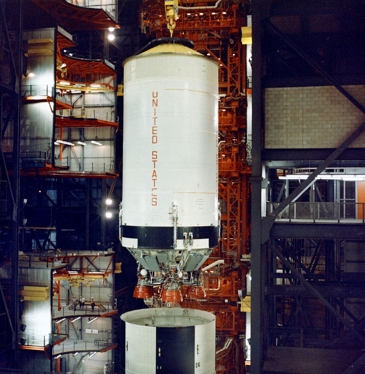
S-II-1 Stacked with AS-501,
Vehicle Assembly Building (NASA)
U.S. Manned Rocket Propulsion Evolution
Part 8.20: The Saturn V S-II Stage
Compiled by Kimble D. McCutcheon
Published 1 Jun 2021; Revised 3 Aug 2022
S-II-1 Stacked with AS-501, Vehicle Assembly Building (NASA) |
The Saturn V S-II stage boosted the vehicle from an altitude of about 40 miles and a speed of about 6,000 mph to an altitude of about 115 miles and a speed of about 15,500 mph. The S-II was 81.5 feet long, 33 feet in diameter, weighed about 88,400 lb (98,659 lb including the S-IC/S-II interstage) empty and about 1,034,900 lb fully-fueled. It was powered by five liquid propellant J-2 rocket engines that developed a nominal vacuum thrust of 228,000 lb each for a total of 1,140,000 lb. The four outer J-2 engines were equally spaced on a 17.5 foot diameter circle and were capable of being gimbaled ± 7.0° for thrust vector control. The fifth engine was fixed and mounted on the stage centerline. The S-II burned for about six minutes. After engine cutoff the S-II stage separated from the S-IVB third stage, reentered the atmosphere, mostly disintegrated due to reentry loads, with the remaining debris falling into the Atlantic Ocean west of the Canary Islands. |
S-II Development
In December 1959, a committee chaired by Abe Silverstein recommended development of a LH2-LOX S-II stage based on a high-thrust, liquid-hydrogen-fueled engine. Rocketdyne won the J-2 engine contract while NASA proceeded with long and convoluted stage design studies phase. In the mean time, MSFC requested S-II proposals from 30 aerospace companies, but only 4 made the final cut; North American Aviation (NAA) was ultimately announced the winner on 11 Sep 1961. The government built production facilities at Seal Beach, California, a process that required a tenuous coordination between NASA, the customer, Navy, the construction agency, and NAA, the vendor. Nevertheless, by Fall 1963 NAA was building S-II hardware components.
Like most things aeronautical, Apollo payloads gained weight far beyond their weight budgets and the launch stages had to be commensurately lightened. To get each additional pound of payload, about fourteen had to be cut from the S-IC, five from the S-II and one from the S-IVB. By the time the weight problem became critical the S-IVB was already in production and removing 14 pounds from the S-IC for every 1 pound of payload was impractical; NASA insisted the S-II be lightened.
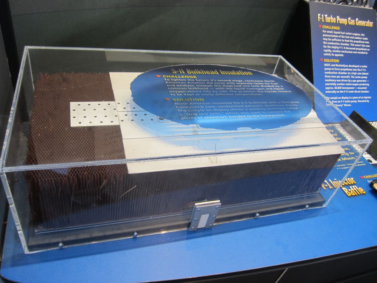
The S-II was very advanced for the existing state of the art. For example, the tank structure accounted for slightly over 3% of the gross weight, but NAA soldiered on with its attempts to lighten the stage. A common bulkhead between the LH2 and LOX tanks was the largest yet attempted, but it eliminated the need from an interstage structure, reducing the S-II's length by nearly ten feet and its weight by nearly 9,000 lb. The bulkhead construction posed numerous challenges, requiring 20-foot welds accurate to 0.011". These welds were applied to 2014 aluminum alloy gores that had been explosively-formed to a complex shape. Another huge challenge was the insulation between the LH2 and LOX sides of the bulkhead.
Common bulkhead fabrication required many carefully-timed operations. Honeycomb phenolic insulation material was bonded to the LOX tank upper half and cured in a huge autoclave. The forward dome that was to became the LH2 bottom half was then test-fitted, revealing insulation areas that needed to be removed or filled for a perfect fit. Finally, the forward dome was bonded to the insulation and checked ultrasonically for a perfect bond. Since the chemically-milled and explosively-formed gore thicknesses tapered from about 0.5" at their base to 0.031" at their apex, the domes tended to sag. NAA finally worked out a scheme that pressurized the dome bottom and a vacuum bell for the top dome, all of which kept the flimsy parts stable through the production process.
A J-shaped periphery at the bottom edge of the forward sheet provided a welding surface that was used to weld the rest of the LH2 tank. The J-section was strengthened by bolting ring with 636 high-strength bolts attached the tank structure to the aft skirt. The bottom LH2 barrel section was just 27" high while the remaining 5 barrel sections were 94.5" high. The barrel sections were each welded in four sections from curved aluminum skins that were machine-milled to leave stringers and ring frames for both structural rigidity and for mounting the internal slosh baffles. The LH2 forward bulkhead was fabricated of 12 gores, in much the same way as the LOX tank lower bulkhead.
NAA decided to use external insulation to help strengthen the LH2 tank, but this choice presented difficulties in boding the insulation to the super-cold tank surfaces. Early tanks applied panels of phenolic honeycomb insulation, which sealed all around with phenolic laminate followed and a layer of Tedlar plastic film. Unfortunately, air- pockets next to the -423°F metal could be turned into puddles of liquid air, which could weaken the bonding and allow the large panels to peel off. A complex helium purge scheme was supposed to prevent this, but was only marginally successful. Later stages used spray-on insulation, which was cheaper to apply and stayed put much better.
Most of the S-II was made of 2014 T6 aluminum alloy, which is very difficult to weld. NAA chose this material because of its strength at cryogenic temperatures. This, coupled with the large stage size, that included numerous circumferential welds each over 100 feet long, varying material thicknesses, and the requirement for nearly perfect fit-up and cleaning made the production of good welds difficult. NAA relied on automated welding for much of this work because the exacting requirements of continually changing weld parameters overwhelmed human operators. Weld schedules for each weld were developed by trial-and-error. A welding technician monitored the progress and made tiny adjustments to compensate for variables such as humidity and barometric pressure. Two welds on opposite sides of the tank sections were often made simultaneously so as to reduce distortion.
One of the most taxing welds joined the forward LH2 bulkhead to the uppermost LH2 tank cylinder where a mismatch of more than 0.028" was too much. But this particular weld near the end of the whole assembly effort suffered from the combined errors of everything that had happened before, and considerable rework was necessary. NAA reduced the assembly building's humidity, established a clean-room atmosphere, made workers wearing white lint-free smocks and gloves enter through air locks with electric shoe-brushing machines to remove dirt. The epoxy clean-room floors were continually mopped, and no smoking or eating was allowed.
The approach to welding was also changed. NAA had used a skate that traveled around the S-II; MSFC had pioneered a technique where the welding torch was stationary while the complete tank rotated on a motorized table. New fixtures maintained much tighter control over weld geometry by clamping the weldment every few inches. This made the trimming, fit-up and welding much more repeatable and successful. Sadly, these processes were slow in coming and NAA did not make an error free bulkhead-to-cylinder joint until January 1968, when only six S-IIs left to produce.
On 28 Oct 1964, the first completed aft bulkhead ruptured at a repaired weld during a hydrostatic proof test. This, along with other production problems led to a series of delays, schedule slips, and NASA oversight committees. For a time it looked as if the S-II stage would cause the Saturn V and NASA to miss its end-of-the-decade schedule.
On 29 Sep 1965, the S-II-S/D (structures-dynamic test stage) ruptured and disintegrated during a loading test at Seal Beach. An October letter from MSFC to Harrison Storms, the president of S&ID, stated that, "The continued inability or failure of S&ID to project with any reasonable accuracy their resource requirements, their inability to identify in a timely manner impending problems, and their inability to assess and relate resource requirements and problem areas to schedule impact, can lead me to only one conclusion, …that S&ID management does not have control of the Saturn S-II program." Thus began a series of investigations, accusations, recriminations and ultimatums that attacked nearly every level of the S&ID operation. This continued past the Apollo 1 fire on 27 Jan 1967.
Although NAA worked hard to address its problems, its management and technical teams were spread too thin and in many cases inexperienced. On 25 May 1966, during testing of the first operational S-II stage (S-II-T) at the Mississippi Test Facility, one fire near some LH2 valves and another in the engine area cut short a full-duration static test. Then on 28 May 1966, technicians doing LH2 tank pressure checks, unaware that critical safety switches and pressure gauges had been disconnected, over-pressurized the tank and destroyed the stage. Five NAA test crewmen were injured, and two others hospitalized for observation. Further investigation revealed many tiny cracks in the LH2 tank near the rupture area. This cracking was not confined to S-II-T, but also appeared, along with other flaws, in other S-IIs already manufactured. With extensive help from MSFC personnel, NAA finally started to get control of S-II manufacturing, leading to the first successful S-II launch aboard AS-501 (Apollo 4) on 9 Nov 1967.
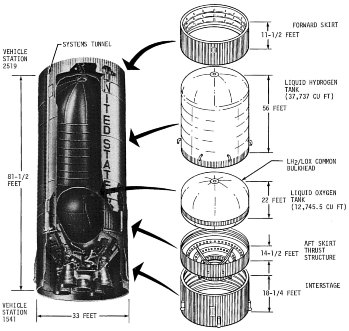 S-II Stage Structure |
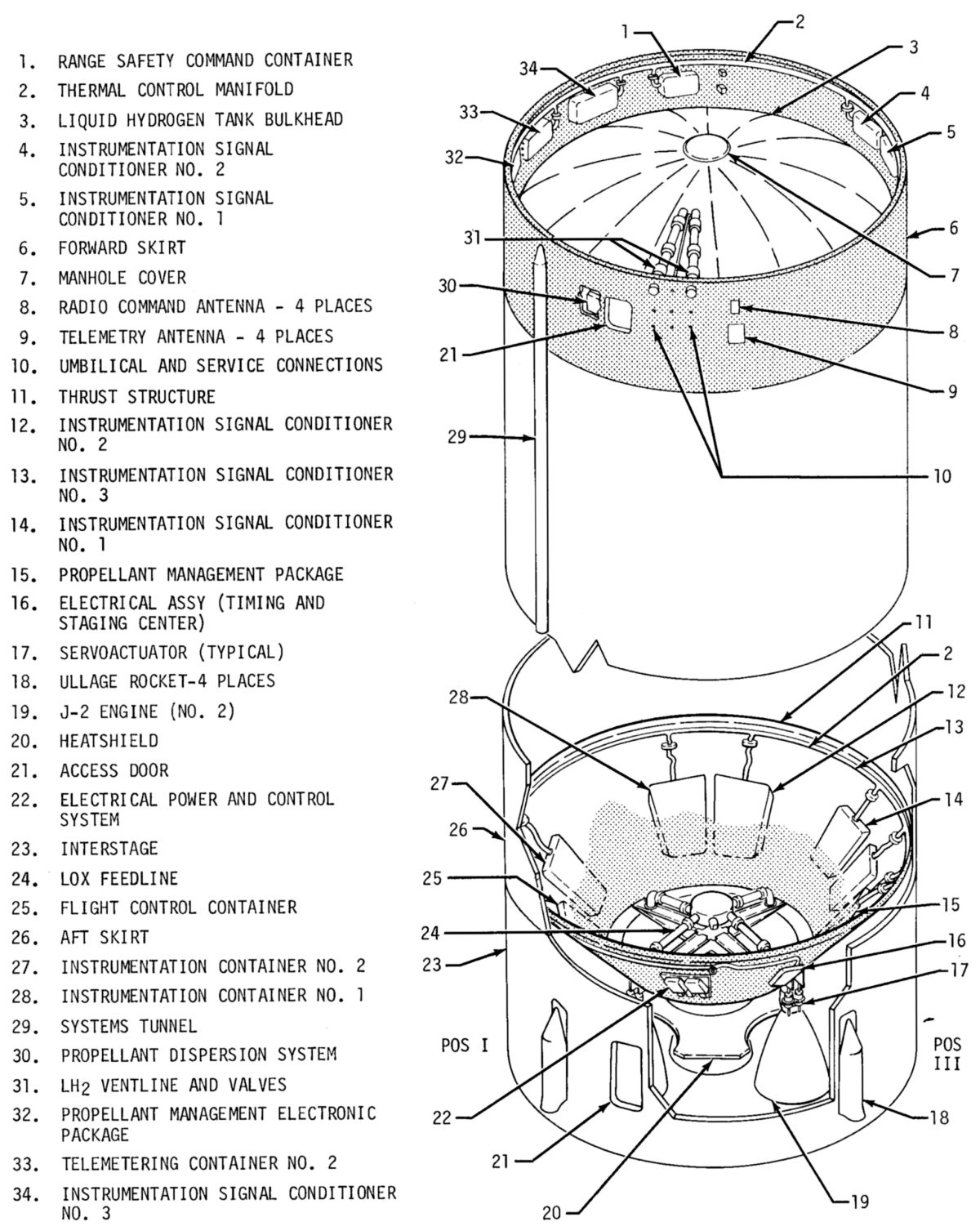 S-II Equipment |
S-II Description
Overview
Nine systems comprised the S-II: structure, propulsion, flight control, environmental control, pneumatic control, propellant, electrical, instrumentation, and ordnance. The S-II interfaced with the S-IC and S-IVB stages electrically and structurally. It also had GSE interfaces for electrical, fluid and pneumatic systems via umbilicals and antennae.
Structure
The S-II structure consisted of a propellant tank structure containing fuel (LH2) and oxidizer (LOX), forward and aft skirts, an interstage, and a thrust structure. The body shell transmitted first and second stage axial, shear, and bending boost loads between adjacent stages. The propellant tank structure connected the aft and forward skirts, while the thrust structure transmitted engine forces to the body shell structure.
The forward skirt, aft skirt, and interstage were of the same basic design. Each unit was a cylindrical shell of semi-monocoque construction, built of 7075 aluminum alloy, stiffened by external hat-section stringers and stabilized internally by circumferential ring frames. The forward skirt had a basic skin thickness of 0.040" while the aft skirt and interstage both had basic skin thicknesses of 0.071".
The thrust structure was also of semi-monocoque construction but in the form of a truncated cone increasing in diameter from the 21.6-foot S-IVB diameter to the 33-foot S-IC diameter. It was stiffened by circumferential ring frames and hat-section stringers. Four pairs of thrust longerons (two at each outboard engine location) and a center engine support beam cruciform assembly accepted and distributed engine thrust loads. The shell structure was of 7075 aluminum alloy. A fiberglass honeycomb heat shield, supported from the lower portion of the thrust structure, protected the stage base area from excessive temperatures during S-II boost. The conical shell also served to support the major portion of S-II system components; some were mounted in environmentally controlled equipment containers, others directly to the structure.
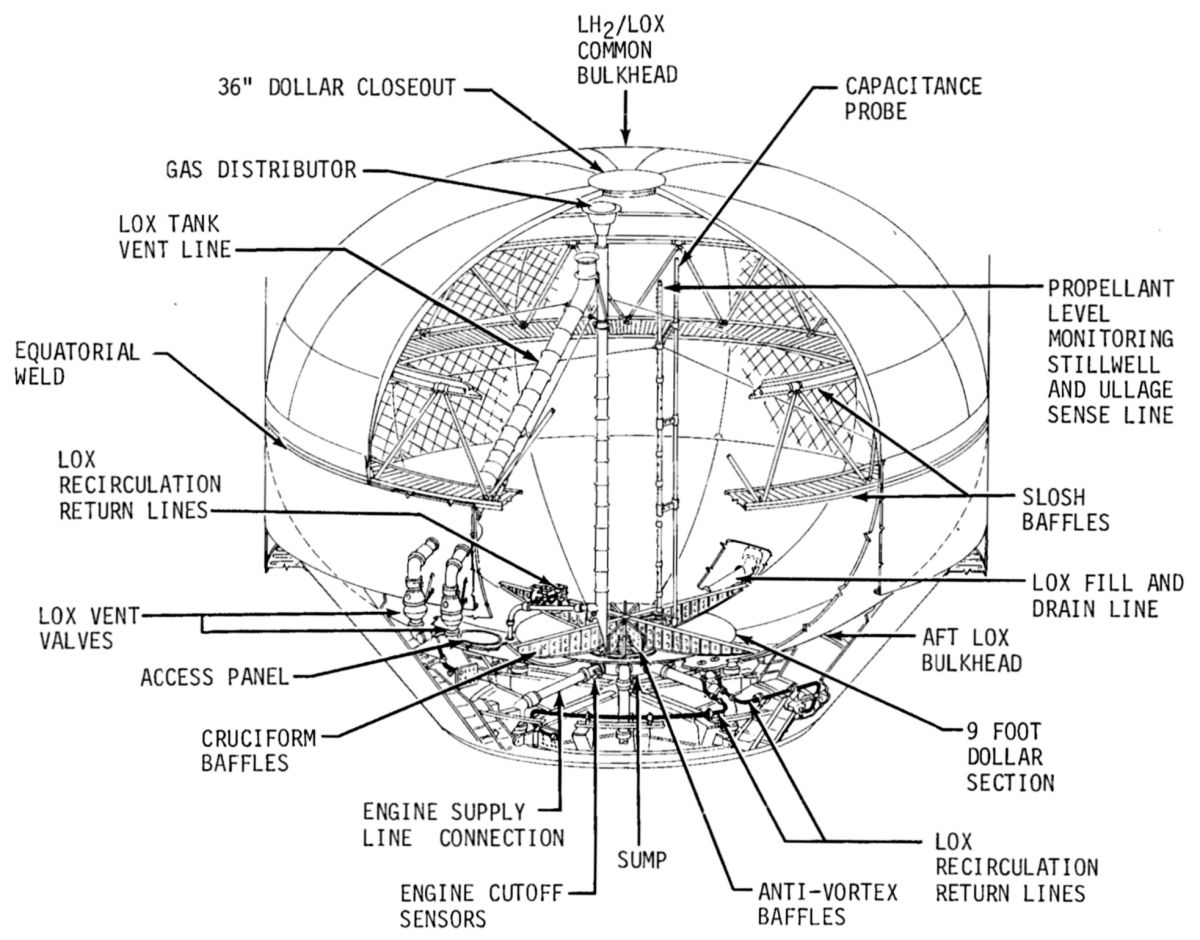 S-II LOX Tank |
The LH2 tank was a long cylinder with a concave modified ellipsoidal bulkhead forward and a convex modified ellipsoidal bulkhead aft. The aft bulkhead was common to the LOX tank. The LH2 tank was fabricated from 2014 aluminum alloy. Six cylindrical sections with longitudinal and circumferential stiffeners were fusion welded together to form the cylinder. The forward bulkhead had a 36" diameter access hole at its center.
The common bulkhead was an adhesive-bonded sandwich with facing sheets of 2014 aluminum alloy and fiberglass/phenolic honeycomb core that helped prevent heat transfer between the LH2 and LOX tanks. Fiberglass core insulation thickness varied from approximately 5" at the apex to 0.080" at the outer extremity. No connections or lines passed through the common bulkhead. The forward skin had a "J" section return at the outer edge to permit peripheral attachment to the LH2 tank while the lower facing was carried through to provide structural continuity with the LOX tank aft bulkhead.
The LOX tank consisted of ellipsoidal fore and aft halves with waffle-stiffened gore segments. Three ring-type slosh baffles helped control propellant sloshing and cruciform baffles prevented vortex formation at the outlet ducts. A six-port sump assembly located at the lowest point of the LOX tank provided a fill and drain opening and openings for five engine feed lines.
An external systems tunnel housed pressurization lines, electrical cables and propellant dispersion ordnance. The tunnel was about 60 feet long and had a semicircular section 22" wide.
Propulsion
The S-II propulsion system consisted of five single-start J-2 rocket engines. The four outer engines , mounted parallel to the stage centerline, were gimbaled to allow thrust vector control. The fixed fifth engine was mounted on the stage centerline. Each engine included a system to detect malfunctions and to affect a safe shutdown. If neither mainstage OK pressure switch had indicated sufficient thrust for mainstage operation of the ignition phase timer, a shutdown of the particular engine was initiated. Once an engine attained mainstage operation, it was shut down if both mainstage OK pressure switches deactuated due to low level thrust.
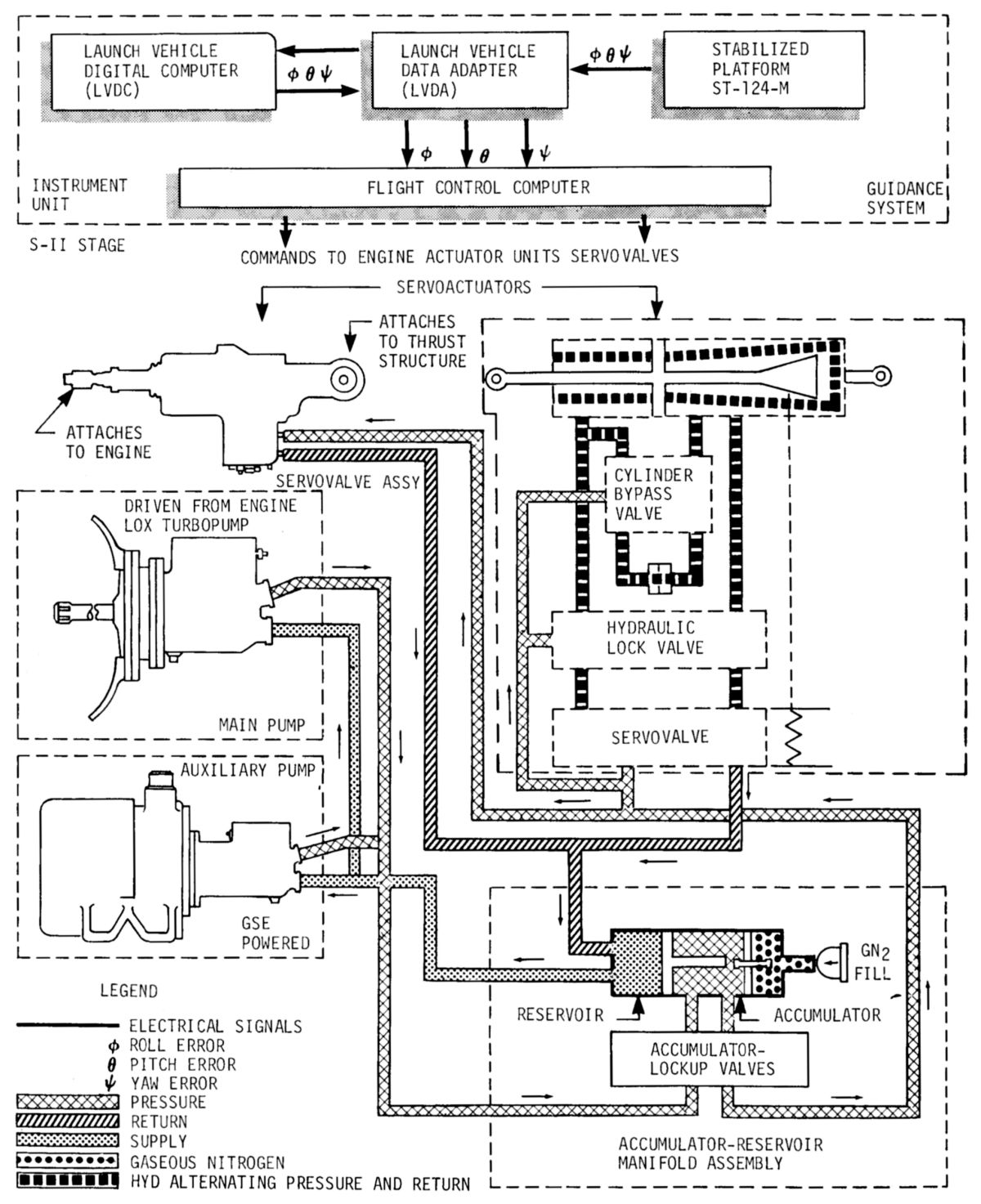 S-II Flight Control System |
 J-2 Articulation |
Flight Control
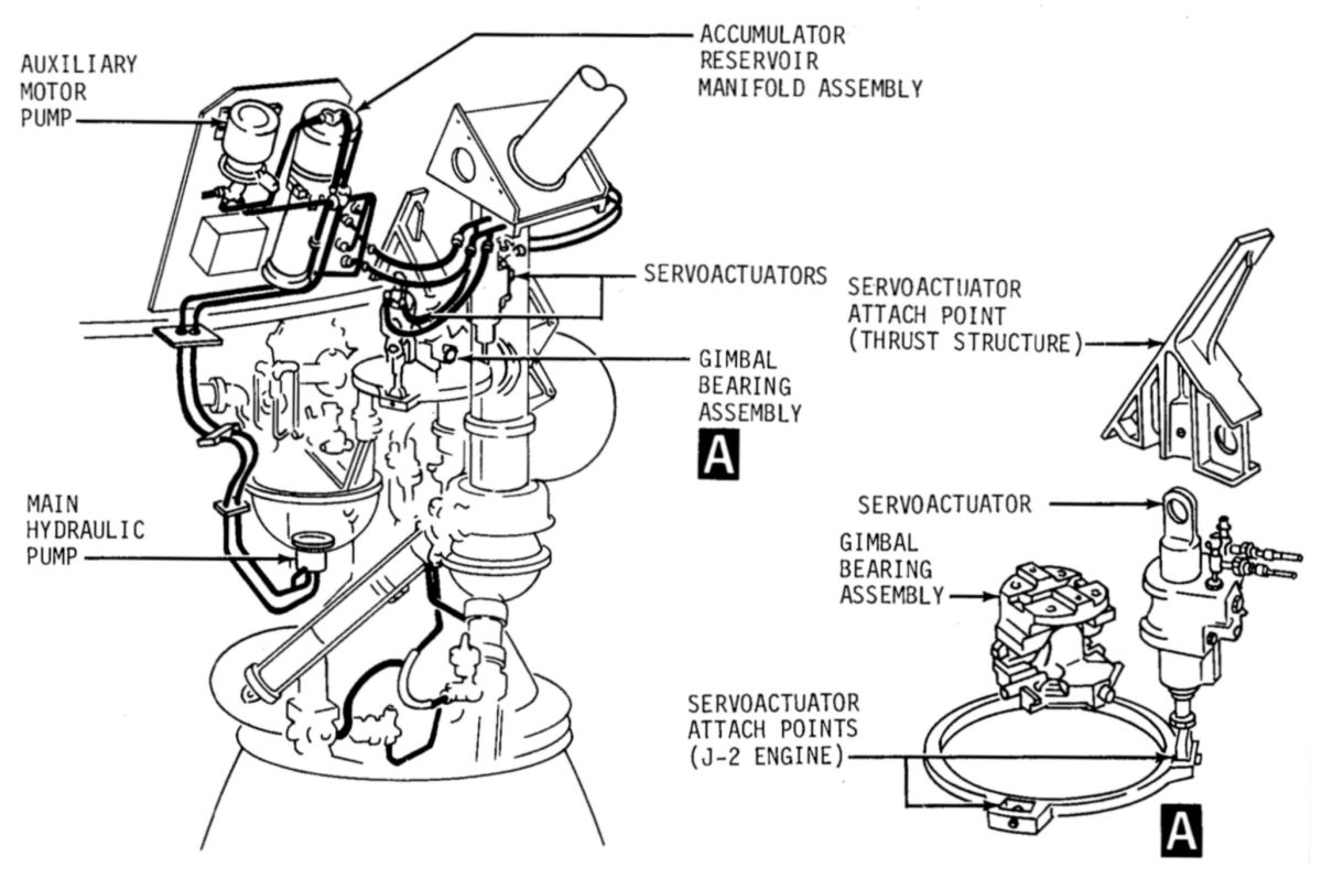
The four outer engines achieved thrust vector control in response to electrical signals from the LVDT. Each outboard engine had a separate, independent, closed-loop, hydraulic control system that included two servoactuators mounted perpendicular to each other. These affected control about the S-II's pitch, roll and yaw axes. The servoactuators were capable of deflecting the engine ± 7° in the pitch and yaw planes, at the rate of 8° per second.
The hydraulic control system included a main pump, an auxiliary pump, an accumulator/reservoir manifold assembly, and two servoactuators. The auxiliary pump, which delivered 2 gpm at 3,650 psig, was driven by a 400 Hz motor on GSE power; it was used prior to launch to keep hydraulic fluid temperature between 65° F and 105° F. The main (flight) pump was mounted to and driven by the LOX turbopump. It delivered hydraulic fluid at 8 gpm and 3,500 psig. Prior to launch, the accumulator was pressurized with GN2 and filled with hydraulic fluid from the pressurized auxiliary pump flow. The reservoir was, in turn, pressurized by the accumulator through a piston-type linkage. The accumulator/reservoir manifold assembly consisted of a high pressure (3,500 psig) accumulator that received high pressure fluid from the pumps and a low pressure (88 psig) reservoir that received return fluid from the servoactuators. During engine firing, hydraulic fluid was routed under pressure from the main pump to the accumulator/reservoir pressure manifold.
The accumulator provided hydraulic fluid under pressure, furnished high pressure fluid for sudden demands and smoothed out pump pulsations. The pressurized hydraulic fluid was directed to the two identical hydraulically-powered servoactuators that accurately positioned the engine in response to flight control system signals. Guidance system command signals were interpreted as linear variations from a known piston position. Hydraulic fluid was then directed to either side of the actuator piston as required to satisfy the guidance command. Actuator return fluid was routed to the reservoir that stored hydraulic fluid at sufficient pressure to supply a positive pressure at the main pump inlet.
During and following propellant loading, the hydraulic system fluid was intermittently recirculated by the electrically driven auxiliary pump in order to prevent the fluid from freezing. Recirculation was terminated just prior to the S-IC stage ignition command. Recirculation was not necessary during S-IC burn, due to its short duration. At approximately T-42 minutes, fluid was stored under high pressure in the accumulator by closing both hydraulic lockup valves contained in the accumulator/reservoir manifold assembly.
After S-IC/S II stage separation, an S-II switch selector command unlocked the accumulator lockup valves, releasing high pressure fluid to each of the two servoactuators. The accumulator stored fluid provided gimbaling power prior to main hydraulic pump operation. During S-II mainstage operation the main hydraulic pump supplied high pressure fluid to the servoactuators for gimbaling.
Pneumatic Controls
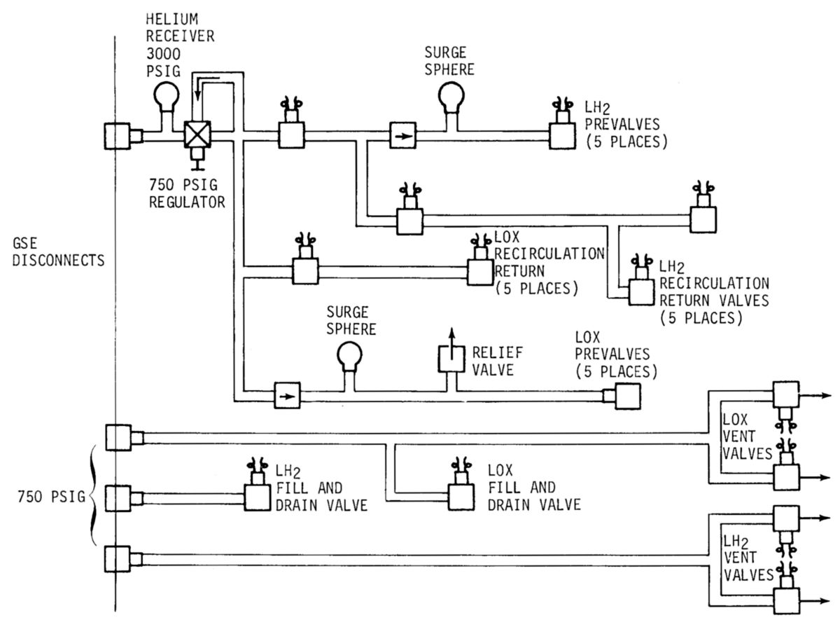
The pneumatic control system had ground and onboard components. The ground system utilized helium supplied directly from a ground source and the onboard system utilized helium from onboard storage spheres. Ground supplied helium controlled and actuated various valves during preflight operations. These included the vent valves, fill and drain valves, recirculation return line valves, and main propellant line prevalves. The stage onboard pneumatic control systems consisted of a propellant valve control, engine pneumatic actuation and engine purge. The stage onboard pneumatic control system was supplied from the helium receiver. It was pressurized to 3,000 psig at approximately T-31 minutes. Pneumatic pressure from the helium receiver was regulated to 750 psig by the control regulator and was used during flight to actuate the prevalves and recirculation valves.
 |
 |
| Pneumatic Controls | Valve Actuation |
Environmental Control
The environmental control system received dehumidified, thermally-conditioned air and nitrogen from a ground source for temperature control and compartment purging during prelaunch operations only.
The thermal control system provided temperature control to equipment containers mounted in the forward and aft skirt. It became operational shortly after the vehicle was mated to pad facilities. Air was used as the conditioning medium until approximately twenty minutes prior to LH2 loading. At this time GN2 was used until umbilical disconnect to preclude the possibility of an explosion in the event of LH2 leakage. The change to GN2 was made before propellant loading to ensure that all oxygen was expelled and dissipated before a hazard could arise. The nitrogen flow was terminated at liftoff, and no flow was provided during boost, since the equipment container insulation was capable of maintaining equipment temperatures during S-II flight.
The engine compartment conditioning system maintained compartment temperature and purged the engine and interstage areas of explosive mixtures. Purging began prior to propellant tanking and continued whenever propellants were on board. A 98% GN2 atmosphere circulating through the compartment maintained desired temperature while the danger of fire or explosion resulting from propellant leakage was minimized.
All exposed surfaces of the LH2 tank required insulation to prevent condensation and to reduce temperature rise during cryogenic operations.
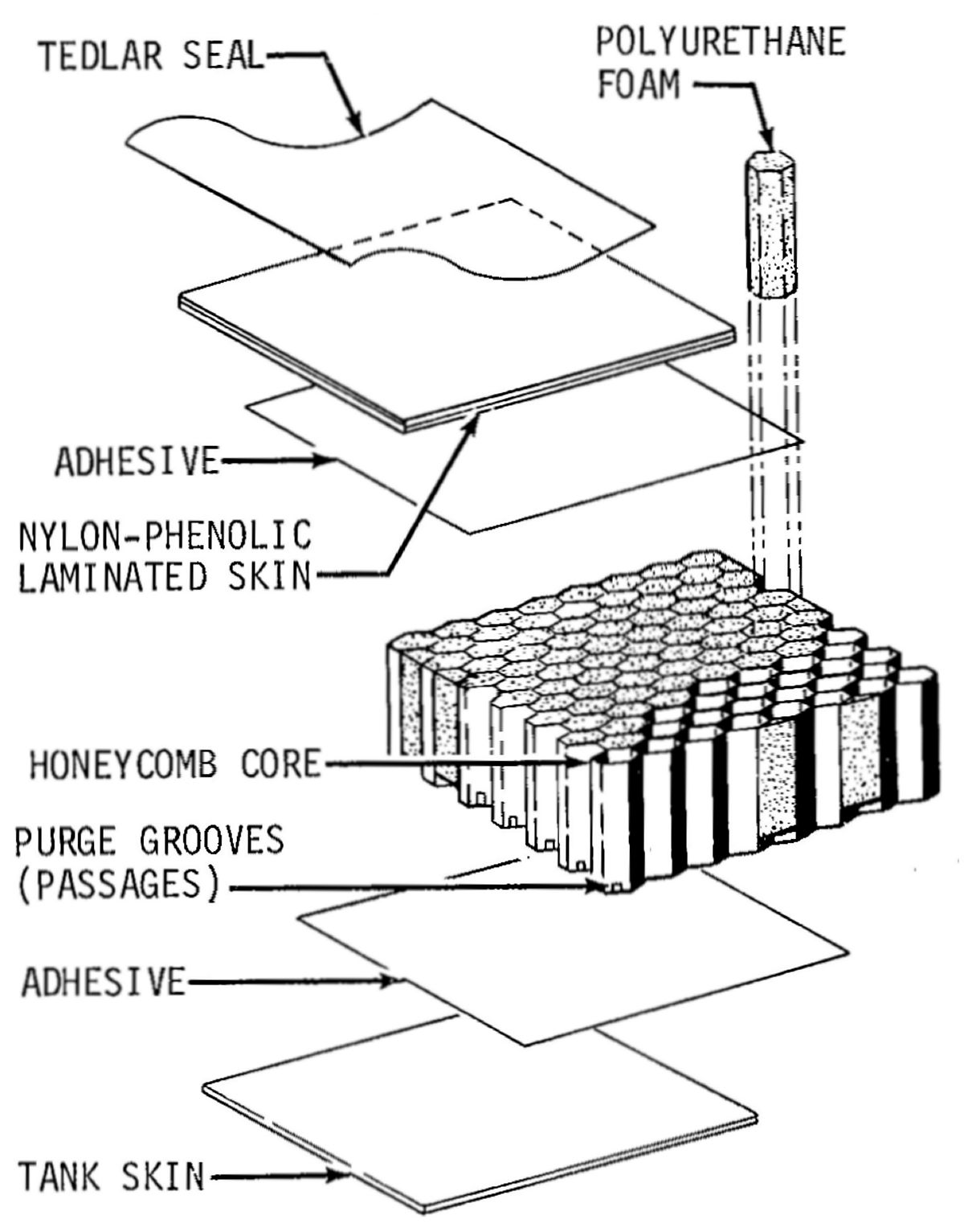
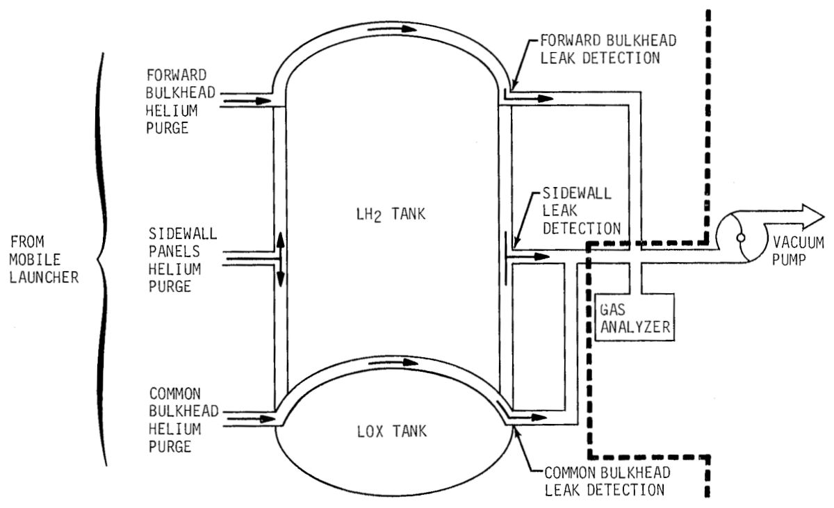
The Insulation/Purge feature removed air that could potentially contact the LH2 tank's surface. Such contact would result in air liquefaction and when the liquid air boiled the resulting pressure would pop insulation loose from the tank. The insulation material was a foam-filled honeycomb about 1.6" thick on the LH2 tank sidewalls, and 0.5" thick on the forward bulkhead. The insulation had a network of passages through which helium gas flowed. The areas to be purged were divided into several circuits: the LH2 tank sidewalls, forward bulkhead, the common bulkhead, the LH2 tank/forward skirt junction, and the lower LH2 tank/bolting ring areas.
The purge system was used in conjunction with the leak detection system in the LH2 tank sidewall, forward bulkhead, and common bulkhead areas to provide a means of detecting any hydrogen, oxygen, or air leaks while diluting or removing the leaking gases. From initiation of propellant loading until launch, the insulation was continuously purged of hazardous gases and a GSE gas analyzer determined any leakage in the purged gas.
 |
 |
 |
| LH2 Tank Insulation | S-II Common Bulkhead Insulation | Insulation Purge and Leak Detection |
Propellants
The propellant systems supplied fuel and oxidizer to the engines. This was accomplished by the propellant management components and the servicing, conditioning, and delivery subsystems.
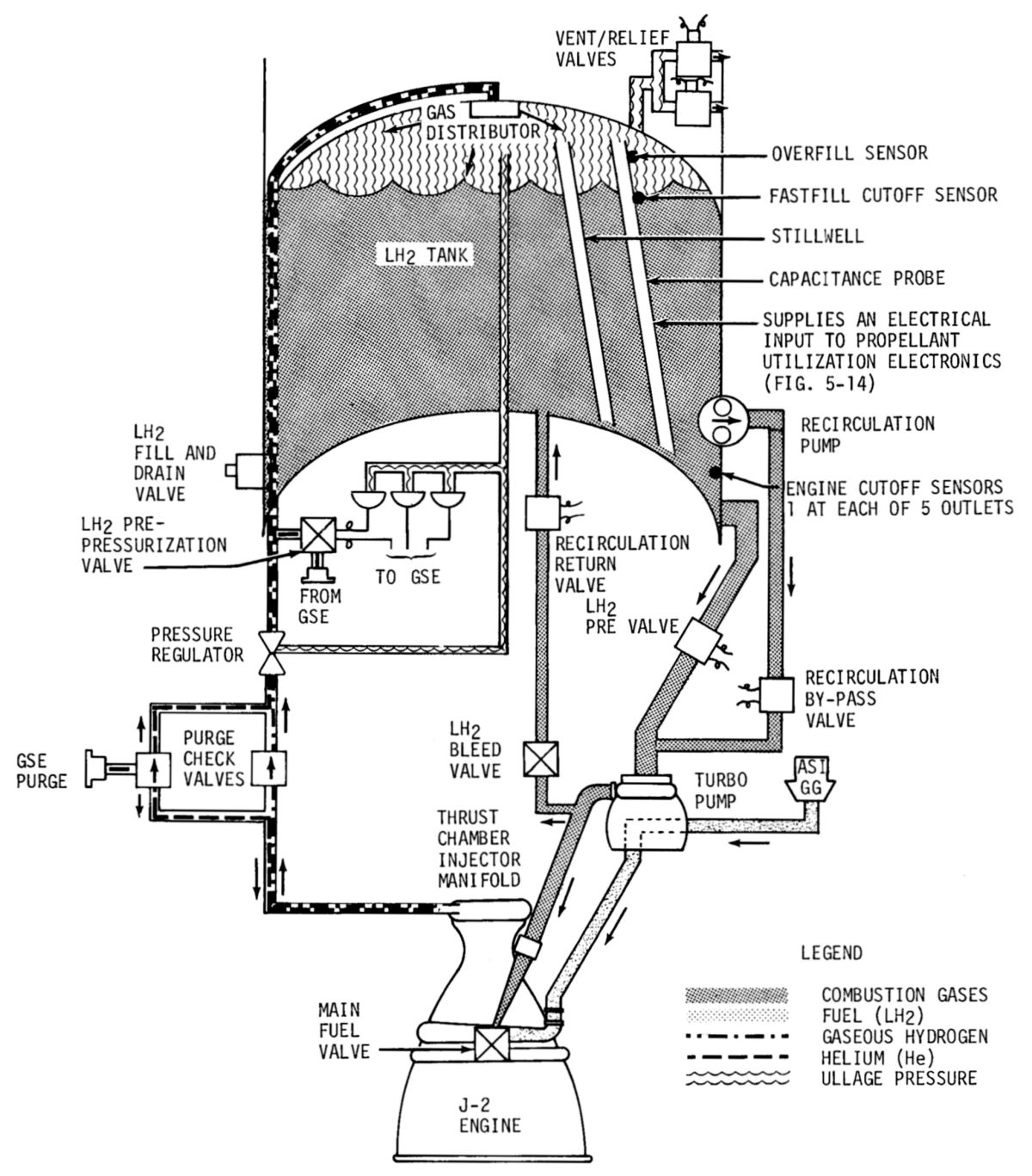
The Propellant Servicing Systems supported pad servicing operations including propellant tank and line filling, draining, and purging. Ground interface was through the umbilicals, to the fill and drain valves, and into the propellant tanks. Propellants entered the engine feed lines, stopping at the closed main valves.The tanks were vented by opening the two tank vent valves, which allowed ullage gas to escape from the tanks.
Propellant tanks vent valve actuation pressure was provided by two separate 750-psig ground-supplied helium systems. One system actuated the LOX tank vent valves, and the other system actuated the LH2 tank vent valves. The vent valves were open during propellant loading operations and closed for tank pressurization. If the launch was aborted, propellant tank draining was accomplished by pressurizing the tanks, opening the fill valves, and reversing the fill operation.
Propellant recirculation maintained uniform cryogenic density, temperature, and precluded formation of gas in propellant plumbing. This gas could cause turbopump cavitation during engine start, result in a slow engine start, cause slow thrust buildup or cause power surges.
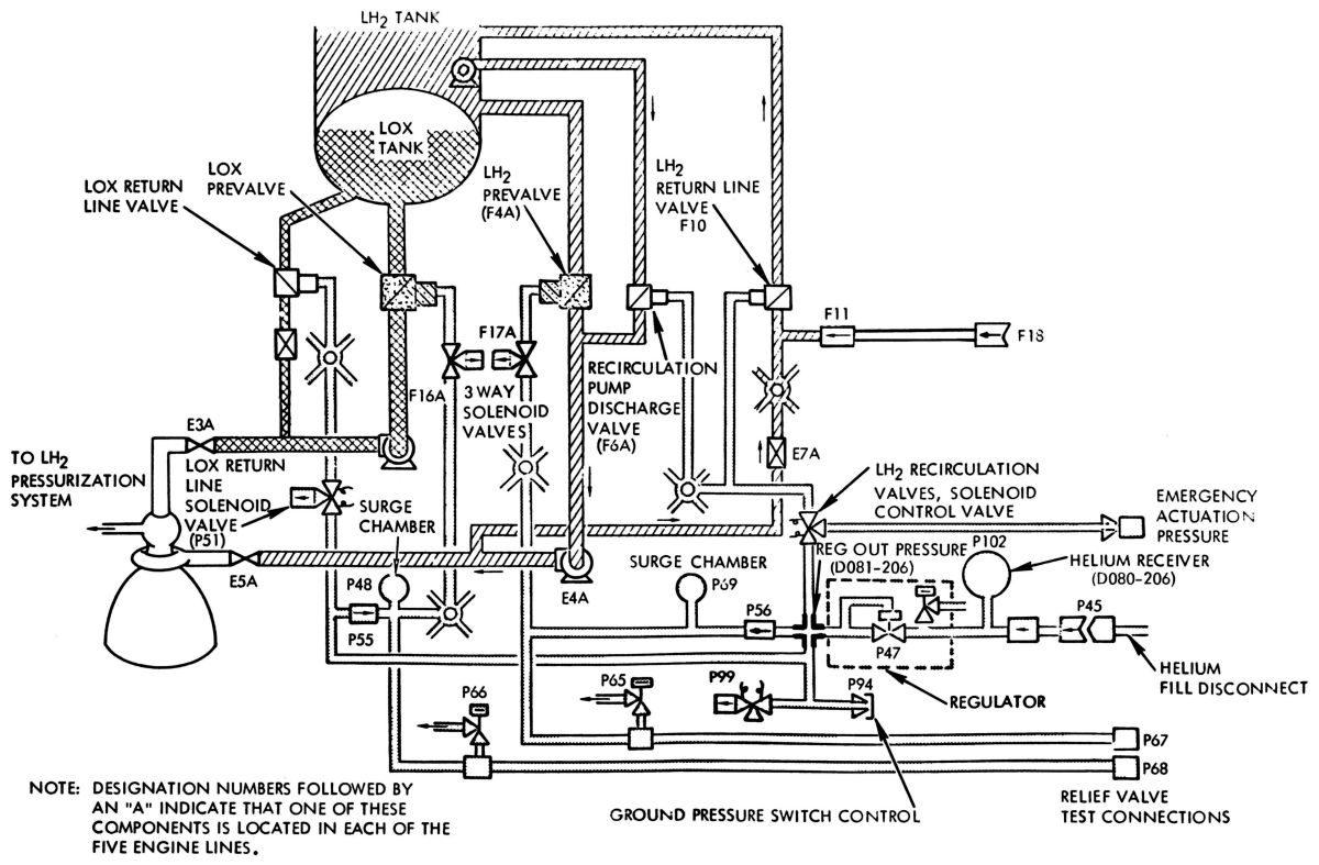
LOX conditioning by natural convection began shortly after start of LOX fill and continued until T-30 minutes. At that time, helium was injected into the LOX recirculation return line to boost recirculation. Helium boost was continuous until just prior to S-II ignition. After launch, helium was supplied from a pressurized sphere. During recirculation, LOX prevalves and recirculation return valves remained open. Return line valves were closed at termination of recirculation. LOX conditioning was accomplished by recirculating the LOX down the engine feed ducts through the prevalves, the LOX turbopump, into the return lines, through the engine bleed valves, and back into the LOX tank.
LH2 recirculation began at approximately T-30 minutes and was terminated just prior to S-II ignition. Forced recirculation during launch and S-IC boost consisted of closing the LH2 feed line prevalves and starting the LH2 recirculation pumps. Each of the five feed ducts had a separate recirculation pump. LH2 was pumped through the recirculation bypass valve, into the LH2 feed ducts downstream of the prevalves, through the LH2 turbopump, LH2 bleed valve, the recirculation return valve, and back into the LH2 tank. Recirculation was terminated by opening the prevalves, stopping the pumps, and closing the recirculation return valves.
Pre-pressurization began after propellant loading was completed, and shortly before liftoff; vent valves were closed and the propellant tanks were pressurized to their required levels by helium from ground supplies. Propellant tank pressurization prior to liftoff provided the required net positive suction head (NPSH) at the turbopump inlets during engine start. It was accomplished from a ground regulated helium source. Pressurization was started by the terminal countdown sequencer at approximately T-3:07 for the LOX tank and T-1:37 seconds for the LH2 tank. Pressurization was terminated at T-30 seconds for the LOX tank and the LH2 tank.
Both propellant tanks were pressurized in the same manner by separate systems. At pre-pressurization start the tank vent valves were closed and the disconnect valve and ground pre-pressurization valves opened allowing GHe at minus 275° F to flow from the ground source through the pre-pressurization solenoid valve into the tank pressurization line. This line carried helium into the propellant tank through the tank gas distributor.
Each propellant tank had a fill overpressure switch for personnel safety. The switch sent a signal to the GSE and was used only during loading. The vent valves acted as relief valves allowing ullage gas to be vented directly overboard during flight. The LH2 vent valves operated between 27.5 and 29.5 psig prior to S-II ignition and at 30.5 to 33.0 psig during S-II burn. The LOX vent valves cracked at 42 psia and reseated at 39.5 psia.
 |
 |
 |
| LH2 System Pressurization, Flow, Conditioning | LOX System Pressurization, Flow, Conditioning | LH2 and LOX Recirculation |
Propellant Delivery Subsystems
The engine feed systems transferred liquid propellants from their tanks to the rocket engines. Each propellant tank had five prevalves that provided open/close control of propellant flow through separate feedlines to each engine. The prevalves were normally open, pneumatically actuated, electrically controlled, butterfly-gate type valves. Built-in four-way pneumatic control solenoids permitted 750 ± 50 psig helium pressure to actuate the prevalves. If pneumatic pressure or electrical power loss occurred the prevalves were spring actuated to the open position. The prevalves remained open during S-II powered flight unless a signal was received from the engine shutdown system.
The LOX feed system included four 8", vacuum jacketed feed ducts, one uninsulated feed duct, and five normally open prevalves. At engine start, LOX flowed from the tank, through the prevalves and feed lines, to each engine. Approximately 300 milliseconds after main valve closure, the LOX prevalves were closed, providing a redundant shutoff for the LOX feed system.
The LH2 feed system included five 8" vacuum-jacketed feed ducts and five normally open prevalves. The prevalves were closed following tank loading and remain closed until just prior to the S-II ignition command. At engine start, LH2 flowed from the tank, through the prevalves and feed lines, to each engine. Approximately 425 milliseconds after main valve closure the prevalves closed, providing a redundant LH2 feed system shutoff.
LOX tank pressurization was initiated at S-II ignition and continued until engine cutoff. Gaseous oxygen obtained by heating LOX bled from the LOX turbopump outlet. When the turbine discharge pressure reached a pressure differential of 100 psi, a portion of the LOX supplied to the engine was diverted into the heat exchanger where it was turned into GOX. The GOX flowed from each heat exchanger into a common pressurization duct, through the tank pressurization regulator, and into the tank through the gas distributor. The flowrate was varied according to the tank ullage pressure, which was sensed by the reference pressure line connecting the tank and the tank pressurization regulator. The tank pressurization regulator provided continuous regulation of the tank pressure throughout S-II powered flight.
LH2 tank pressurization was initiated at S-II ignition and continued until engine cutoff. Heated GH2 for LH2 tank pressurization was bled from the outboard engine's thrust chamber hydrogen injector manifold after being used for regenerative cooling. The GH2 passed from each injector manifold into a stage manifold, through the pressurization line and tank pressurization regulator, and into the tank through the LH2 tank gas distributor. The flowrate was varied according to the LH2 tank ullage pressure, which was sensed by the reference pressure line connecting the LH2 tank and the tank pressurization regulator. At approximately 5 minutes after S-II engine ignition a step pressurization command from the stage switch selector activated the regulator to a fully open position, where it remains the rest of S-II boost. When the regulator was in the full open position, LH2 tank pressure increased to a nominal 33 psia. LH2 tank vent valves prevented pressure in excess of 33 psia. This step pressurization compensated for the loss of head pressure caused by the lowering of the fuel level in the tank.
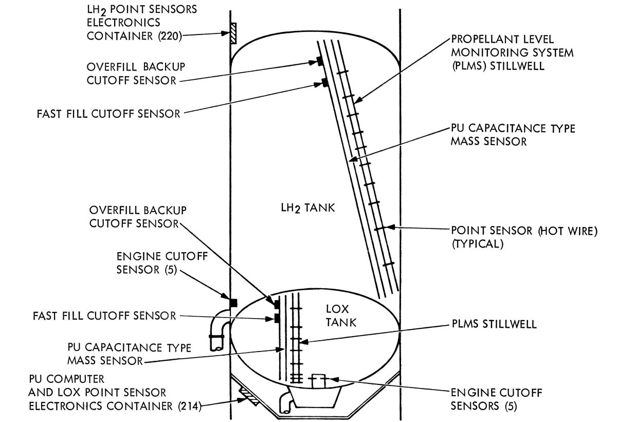
The propellant management systems monitored and controlled propellants during all stage operation phases. LH2 and LOX tank point level sensors and continuous capacitance probes monitored propellant mass. During propellant loading the point level sensors indicated tank levels to GSE. In flight, the level sensors provided signals to the LVDC in order to accomplish a smooth engine cutoff at propellant depletion. Capacitance probes outputs were used to operate the J-2 propellant utilization (PU) control valves, which controlled the LOX quantity flowing to the engines.
The PU subsystem controlled the engine mixture ratios (MR) by regulating LOX flow via a rotary PU valve on each engine. This valve is neutral at engine start, resulting in a nominal 5.0:1 MR. About 5.5 seconds after engine start the LVDC commands a PU valve setting that results in a 5.5.1 MR. Once the launch vehicle achieves a pre-programmed velocity increase a 4.3:1 MR is commanded for the remainder of the burn; this occurs at about 5.5 minutes after engine start.
Five discrete liquid level sensors in each propellant tank initiate engine cutoff when propellant depletion is imminent. The LH2 tank sensors were located above each feedline outlet while the LOX tank sensors were located directly above the sump. The shutdown signal was initiated when two of five engine cutoff signals from the same tank were received.
 |
 |
 |
| Propellant Utilization System Schematic | Propellant Utilization System Block Diagram | Propellant Management System |
 S-II Stage Power Distribution |
Electrical
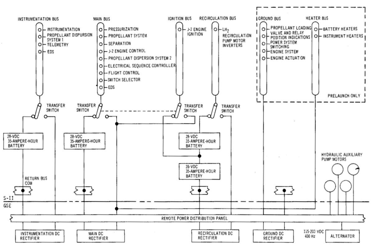
Electrical power and electrical control subsystems comprised the electrical system. The electrical power system supplied electrical power source and distribution. The electrical control system interfaced with the IU to sequence the various S-II functions.
The electrical power system consisted of six DC bus systems and a ground-supplied AC bus system. In flight the electrical power system busses were energized by four zinc-silver oxide batteries. An integral heater and temperature probe were included in each battery. Power for battery heaters and for auxiliary hydraulic pump motors was supplied by GSE and was available only during prelaunch operations. Stage-mounted motor driven power transfer switches were employed to remotely disconnect all batteries from busses just before launch. Approximately 50 seconds prior to liftoff, a power transfer sequence was initiated that changes the source power over to the stage mounted batteries. During the prelaunch checkout period all electrical power was supplied from GSE. The motorized make-before-break (MBB) power transfer switches prevented power interruption during power transfer from ground to onboard battery power.
Each power source had an independent distribution system. There were no provisions for switching between the primary power sources or their associated distribution systems. No electrical failure of any type in one system could cause a failure in the other systems.
The load division between the main DC bus and the instrumentation DC bus resulted in closer voltage regulation and freedom from voltage variations; the number of main DC bus loads was minimized, as were potential failure modes. Instrumentation of most stage systems was still maintained after partial or total main DC bus system failure so that a failure analysis capability always existed.
Primary power was fed to high current capacity busses in the power distributor. Power was then routed to auxiliary and control distributors, or to measuring distributors for instrumentation power. Components that required high current levels were supplied directly from the main power distributor busses.
| Type | Points |
|---|---|
| Acceleraton | 11 |
| Acoustics | 5 |
| Discrete Signals | 225 |
| Flow Rate | 10 |
| Liquid Level | 4 |
| Miscellaneous | 4 |
| Position | 36 |
| Pressure | 192 |
| RPM | 10 |
| Strain | 16 |
| Temperature | 309 |
| Vibration | 72 |
| Voltage, Current, Frequency | 60 |
| Total | 954 |
Instrumentation
 Instrumentation and Telemetry |
The S-II instrumentation system consisted of measurement and telemetry systems. The measurement system monitored and measured conditions on the S-II stage while the telemetry system transmitted this information to ground stations.
The measurement system consisted of transducers, signal conditioners, and distribution equipment that established measurement ranges and presented scaled signals to the telemetry system. The measurement system monitored numerous stage observables, which were processed and conditioned into forms acceptable to the telemetry systems. Measurements fell into a number of basic categories depending upon the type of measured variable, the variable's rate of change with time, and other considerations. Because the stage engines were ignited in flight, a large number of engine and environmental control measurements were required.
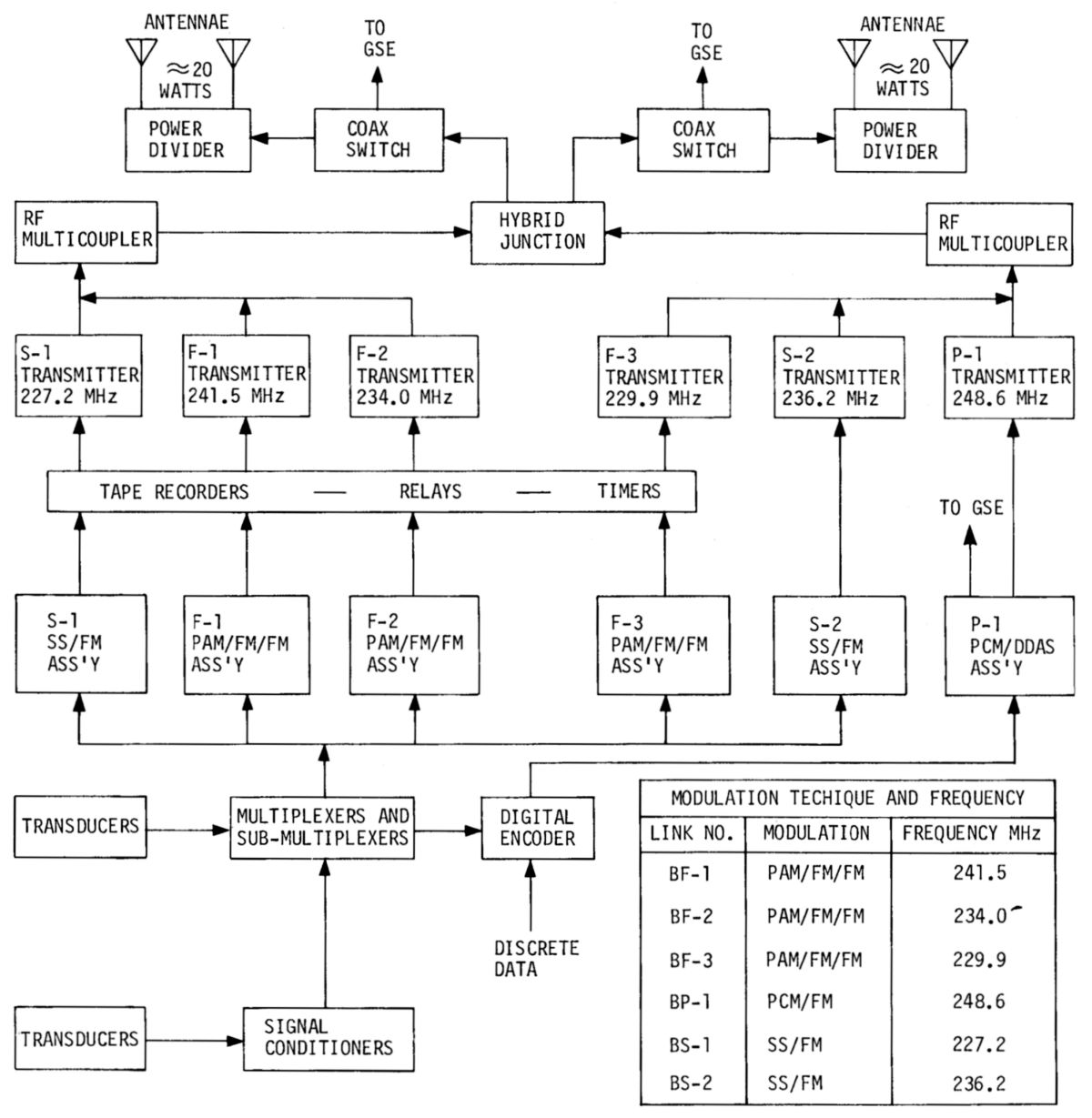
The telemetry system accepted measurement signals and transmitted them to ground stations. Telemetry equipment included signal multiplexers, subcarrier oscillators, amplifiers, modulators, transmitters, RF power amplifiers, RF multiplexers and an omnidirectional system of four antennae.
This equipment also included tape recorders for recording critical data during separation telemetry blackout (separation period) for later play back during stage free fall. The telemetry subsystems used multiplex techniques (signal mixing and time sharing) to transmit large data quantities over a relatively small number of basic RF links. Inflight data was transmitted in the form of frequency-modulated RF carriers in the 225 to 260-MHz band, through the common omnidirectional antenna system. Several telemetry subsystems were provided in the S-II stage. Telemetry data was grouped into low frequency, medium frequency, and high frequency data. The telemetry system employed several different modulation techniques to achieve the necessary data quality and throughput. These modulation techniques included pulse amplitude modulation/frequency modulation/frequency modulation (PAM/FM/FM); pulse code modulation/frequency modulation (PCM/FM) for low-frequency data; and single sideband/frequency modulation (SS/FM) for high-frequency information. A pulse code modulation/digital data acquisition system (PCM/DDAS) transmitted measurements by coaxial cable for automatic ground checkout of the stage. The PCM/DDAS assembly converted analog transducer signals into digital representations, combined these representations with direct inputs, such as those from the guidance computer, and arranged this information into a format for transmission to the ground station on a 600 KHz carrier signal by means of coaxial cable for ground checkout of the stage.
Four antennae, installed at 90° intervals, were employed to provide omnidirectional coverage. The antennae were linear cavity-backed slot antennae that were fed from a hybrid junction ring and power dividers.
Ordnance
The S-II ordnance systems included the separation, ullage rocket, retrorocket, and propellant dispersion (flight termination) systems.
 Stage Separation Systems |
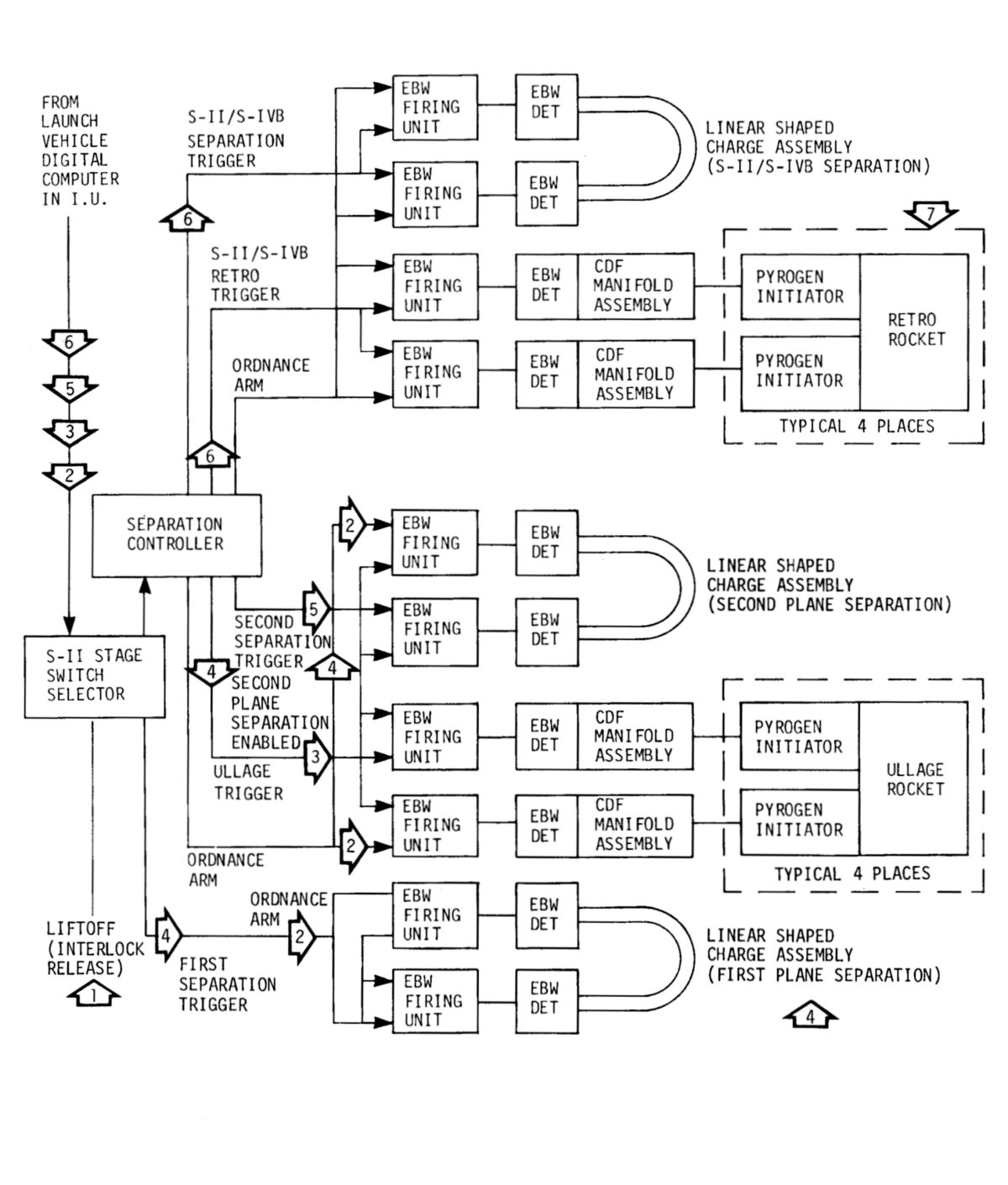 S-IC, S-II, S-IVB Separation |
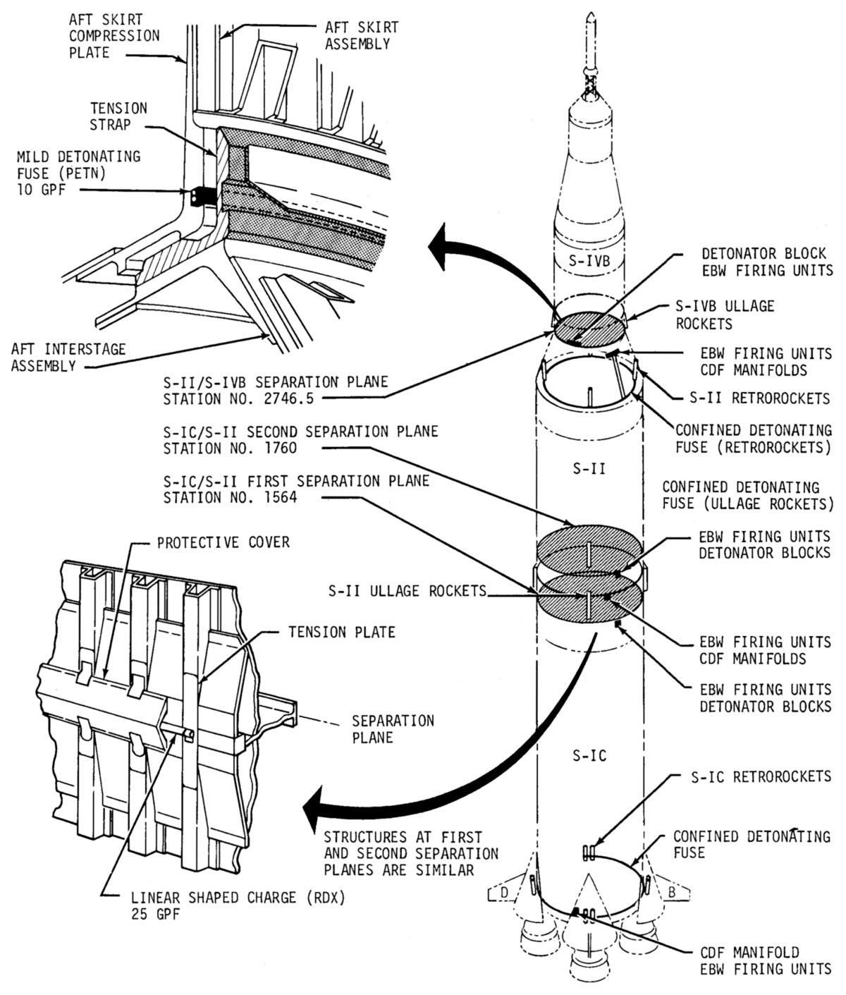
S-IC/S-II stage separation employed a dual plane technique with the structure between the two stages being severed at two different planes. The S-II/S-IVB separation occurred at a single plane. All separations were controlled by the LVDC.
Ordnance for S-IC/S-II first plane separation consisted of two exploding bridgewire (EBW) firing units, two EBW detonators, and one linear shaped charge (LSC) assembly, which included the LSC that contained 25 grains per foot of RDX, with a detonator block on each end. The EBW firing units were installed on the S-IC/S-II interstage slightly below the S-II first separation plane. EBW firing unit leads were fitted to the EBW detonators installed in the LSC assembly detonator blocks attached to adjustable mounts that accommodated LSC assembly length variations and interstage circumference tolerances. The LSC was routed from the detonator blocks around the interstage periphery.
The LSC was held in place by retaining clips and encased by covers that were secured by clips and sealed to environmentally protect the LSC. The two EBW firing units provided redundant signal paths for LSC assembly initiation. A storage capacitor in each EBW firing units was charged by 28 VDC power during the latter part of S-IC boost. The trigger signal caused the storage capacitor to discharge into an EBW detonator, which exploded the bridgewire to release energy and ignited the detonator's explosive charge. Detonation of the LSC assembly severed the tension members attaching the S-IC/S-II interstage at station 1564.
The second plane separation ordnance was similar in composition and function to that of the first plane separation. The EBW firing units were installed on the S-IC/S-II interstage slightly below the separation plane. Detonation of the LSC assembly severed the tension members attaching the S-IC/S-II interstage at station 1760.
No heat-sensitive primary explosives were used and the detonators were not sensitive to accidental application of vehicle or ground power, static discharge, or RF energy. A spark gap in one pin of the firing circuitry prevented burnout of the bridgewire if power was accidentally applied.
This delay permitted transient vehicle motion associated with first plane separation, to dampen out. The separation command was routed to the S-II switch selector and triggerered the ordnance train that ignited the LSC for second plane separation. The LSC detonated, severing the S-II interstage from the S-II stage. The combined effect of vehicle acceleration and the reaction caused by the J-2 engine exhaust plume impingement retarded the interstage.
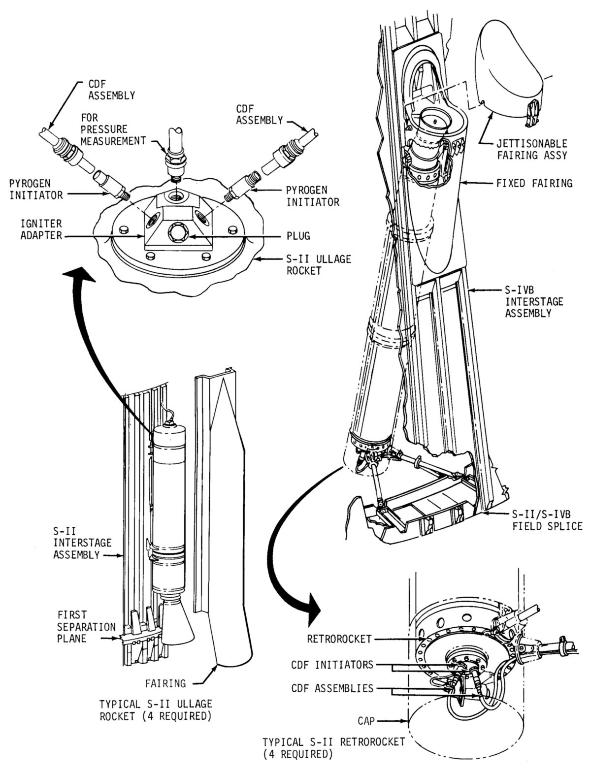
A retrorocket system retarded the S-II stage affecting separation from the S-IVB stage. Two EBW firing units, two EBW detonators, two CDF manifolds, nine CDF assemblies, eight pyrogen initiators, and four Thiokol Elkton TE-M-29-4 retrorockets comprised the system. The components were connected to each other in a manner similar to that of the ullage rocket system. The retrorockets were mounted 90° apart in the aft end of S-II/S-IVB interstage between stations 2519 and 2633. The retrorockets were canted out from the vehicle centerline approximately 3° with the nozzles canted out 9.2° from the centerline.
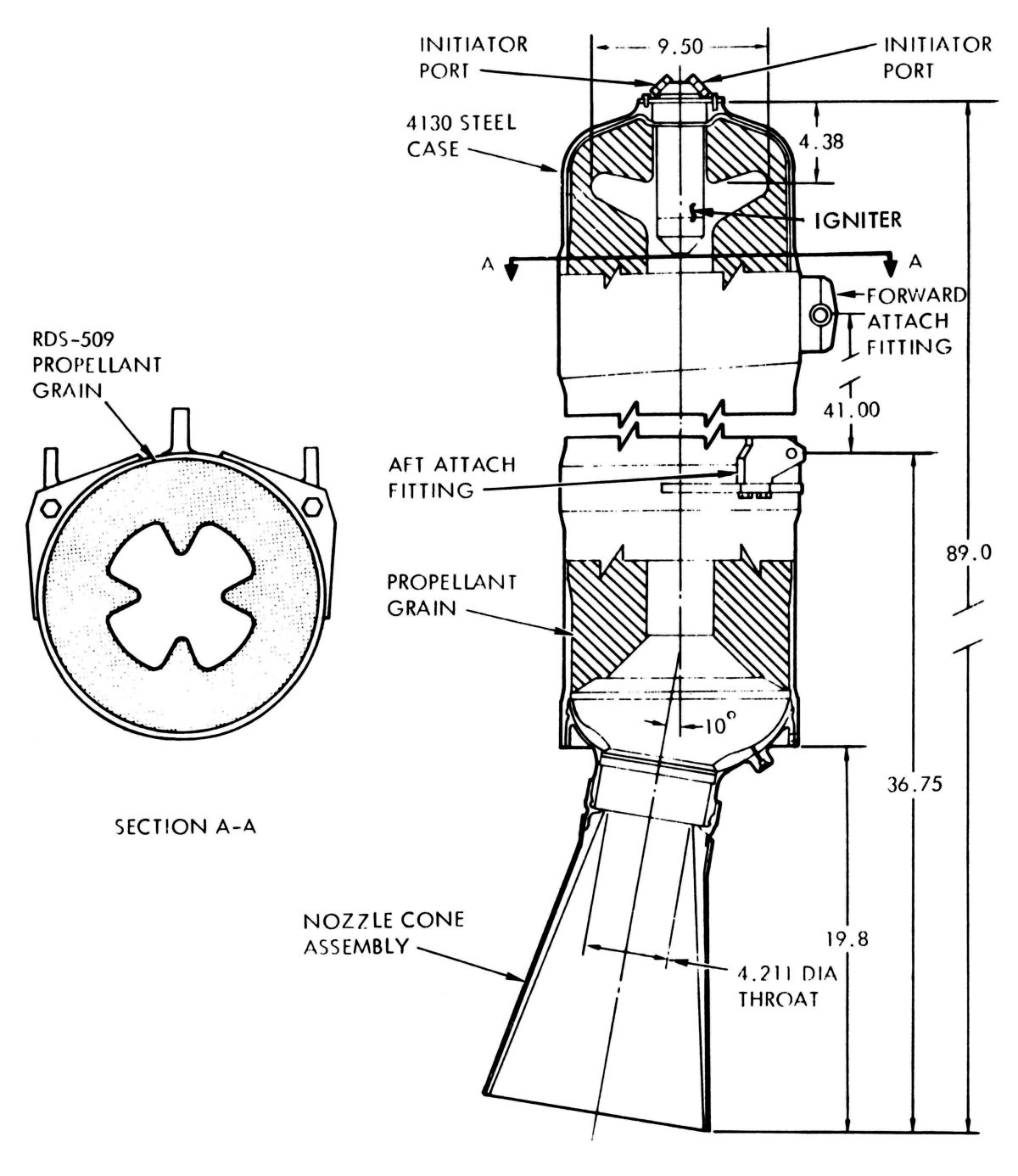
Each retrorocket had a 380 lb gross weight and consisted of a 4130 steel case that was 9" in diameter and 90.68" long containing 268.2 lb of case-bonded, single-grain solid propellant with a tapered, five-point star configuration produceing 34,800 lbT during its 1.52 sec burn time. A steel nozzle raised the retrorocket's total length to 107"/
An ullage rocket system ensured stable propellant flow into the J-2 engines by generating a small forward acceleration that settled the propellants in their tanks.The S-II ullage rocket system consisted of two EBW firing units, two EBW detonators, two combined detonating fuse (CDF) manifolds, nine CDF assemblies, eight CDF initiators and provisions for eight ullage motors; most flights used only four. CDF assemblies connected the two CDF manifolds together and both manifolds to each of the four ullage rockets. The ullage motors were mounted parallel to vehicle centerline 90° apart on the periphery of the S-IC/S-II interstage at its aft end. The nozzles were just above the S-IC/S-II first separation plane and were canted outward 10° to reduce the moment that would result from one or more motors malfunctioning and to reduce exhaust plume impingement. With any one ullage motor inoperative, the remaining ones were capable of maintaining a minimum vehicle acceleration necessary for proper S-II engine ignition.
The RS-U-601 ullage motors were originally built by Rocketdyne in MacGregor, Texas, later by Hercules, Inc. in Wilmington, Delaware . Each 488 lb ullage motor had a 4130 steel case, phenolic exit cone with metal shell, and 337 lb of case-bonded propellant that was 82% ammonium perclorate and 18% carboxy terminated polybutadiene (CTPB) binder cast in a four-point-star grain configuration. The motor was 89" long, 12.5" in diameter, and developed 22,700 lbT for 3.7 seconds.
 |
 |
 |
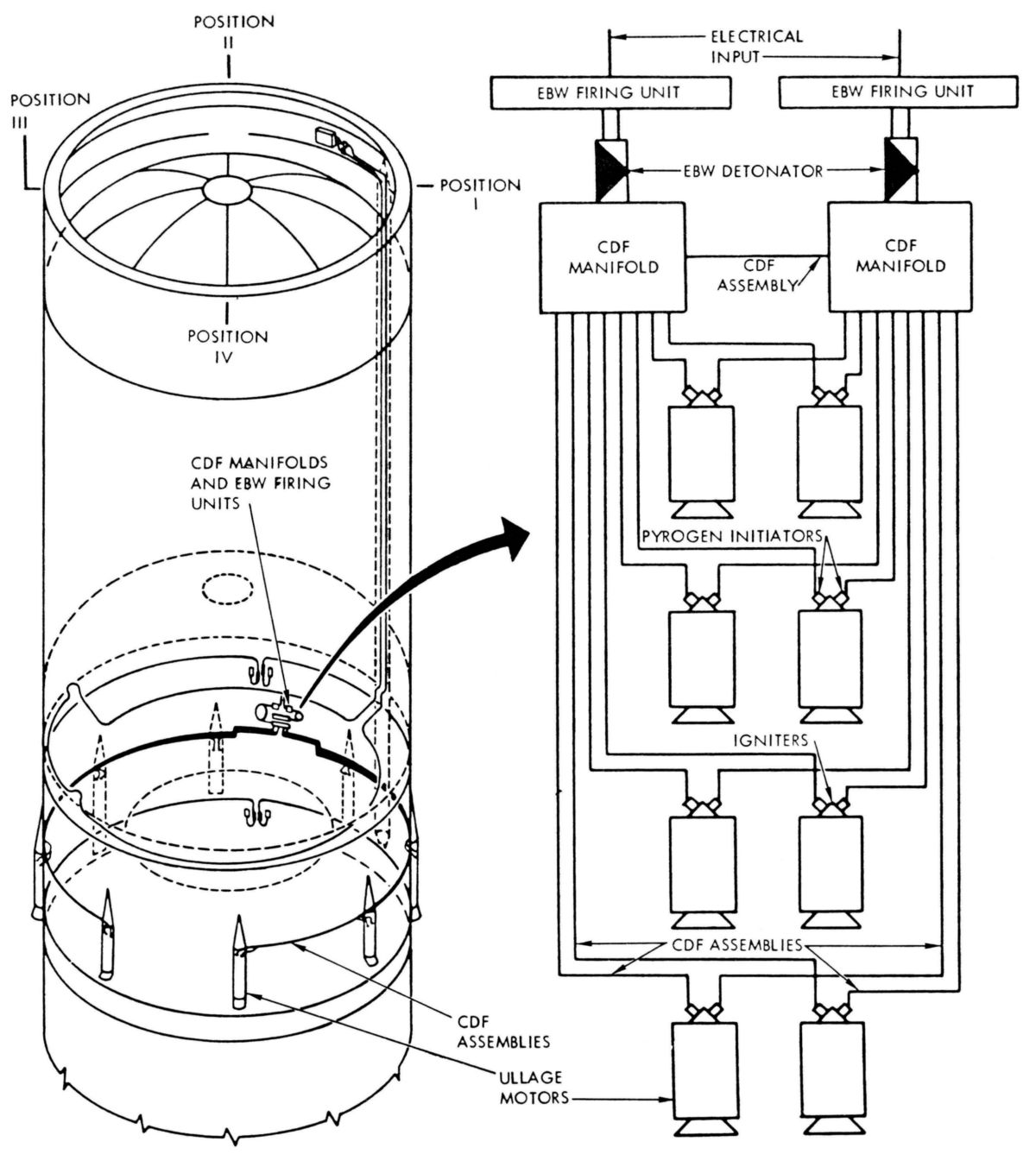 |
| S-II Retro and Ullage Motors | S-II Retro Motor | S-II Ullage Motor | S-II Ullage System. Only Four Ullage Motors Were Used on Later Vehicles |
 Propellant Dispersion System |
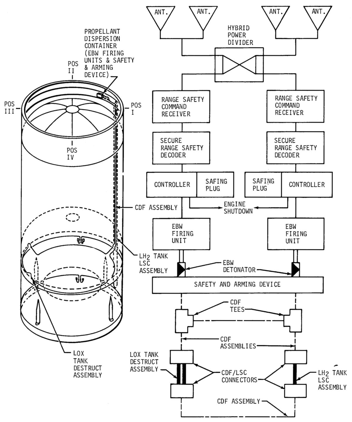
The S-II propellant dispersion system (PDS) terminated vehicle flight during the S-II boost phase if the vehicle flight path varied beyond its prescribed limits or if continuation of vehicle flight created a safety hazard. The S-II PDS was a dual channel, redundant system composed of a radio frequency segment that received, decoded, and controlled the propellant dispersion commands; the ordnance train segment consisted of two EBW firing units, two EBW detonators, one safety and arming (S&A) device (shared by both channels), six CDF assemblies, two CDF tees, one LH2 tank LSC assembly, two LOX tank destruct charge adapters and one LOX tank destruct charge assembly.
If flight termination was necessary, two coded radio frequency commands were transmitted to the launch vehicle by the range safety officer. The first command armed the EBW firing units and initiated S-II stage engine cutoff. The second command, which was delayed to permit charging of the EBW firing units, discharged the in the EBW firing unit storage capacitors across the exploding bridgewire in the EBW detonators mounted on the S&A device. The resulting explosive wave propagated through the S&A device inserts to the CDF assemblies and to the CDF tees. The CDF tees, installed on the S-II forward skirt, propagated the wave to two CDF assemblies that detonated to their respective destruct assemblies. The destruct assemblies were connected by a CDF assembly to provide redundancy.
The LH2 tank linear shaped charge when detonated cut a 30-foot vertical opening in the tank. The LSC assembly consisted of two 15-foot sections of RDX loaded at 600 grains per foot. The LOX tank destruct charges cut 13-foot lateral openings in the LOX tank and the S-II aft skirt simultaneously. The destruct assembly consisted of two linear explosive charges of RDX loaded at 800 grains per foot. The destruct charges were installed in a figure-eight tube mounted on the inside of the aft skirt structure near station number 1831.
References
Bilstein, Roger E. Stages to Saturn NASA SP-4206 (Washington, DC: NASA History Office, 1996)
Engineering Course for Saturn S-II Stage Systems, Volume II: Stage Propulsion and Mechanical Systems. SD-68-654-2 (Seal Beach, California: Space Divisin, North American Rockwell) Nov 1967.
Saturn V News Reference (NASA, Boeing, Douglas, Rocketdyne, North American Rockwell, Dec 1968).
Saturn V Flight Manual, SA-503 (Apollo 8), MSFC-MAN-503 (MSFC, Alabama: MSFC, 1 Nov 1968).
Saturn V Flight Manual, SA-507 (Apollo 12), MSFC-MAN-507 (MSFC, Alabama: MSFC, 15 Aug 1969).
Send mail to
![]() with questions or comments about this web site.
with questions or comments about this web site.
![]()