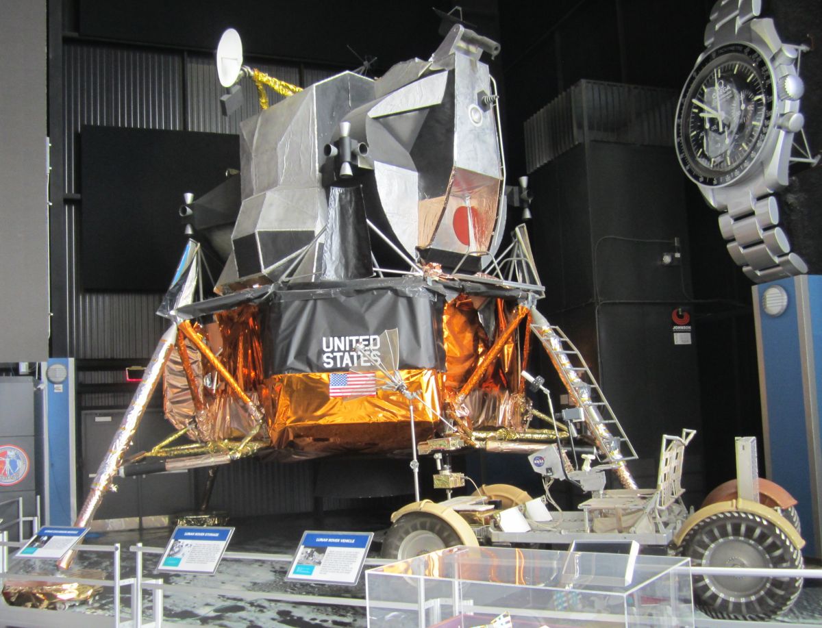
LM Mock Up at the
U.S. Space & Rocket Center
U.S. Manned Rocket Propulsion Evolution
Part 9.40: The Apollo Lunar Module
Compiled by Kimble D. McCutcheon
Published 28 Dec 2021; Revised 4 Aug 2022
LM Mock Up at the U.S. Space & Rocket Center |
The Grumman lunar module (LM) was an exquisite, complicated, ingenious, miraculous, complete spacecraft, capable of a journey from lunar orbit to the earth's moon, landing there, and returning to the host command/service module (CSM), where it docked, deposited its two astronauts and their moon-rock bounty for return to earth. Such a vehicle was a very big deal, especially since it was designed in the early-to-mid 1960s and actually flown in the late 1960s. To have created such a complex, cutting-edge craft at that time is extraordinary beyond belief. Every LM subsystem was newly-engineered and nearly all functioned perfectly. Such a feat, accomplished mostly by engineers whose average age was 28 years, most of whom were recently out of college, and nearly all of whom shared a passion getting to the moon, is nearly unimaginable today. This final installment in the U.S. Manned Rocket Propulsion Evolution series will explore the LM in the detail it deserves. |
LM Introduction
|
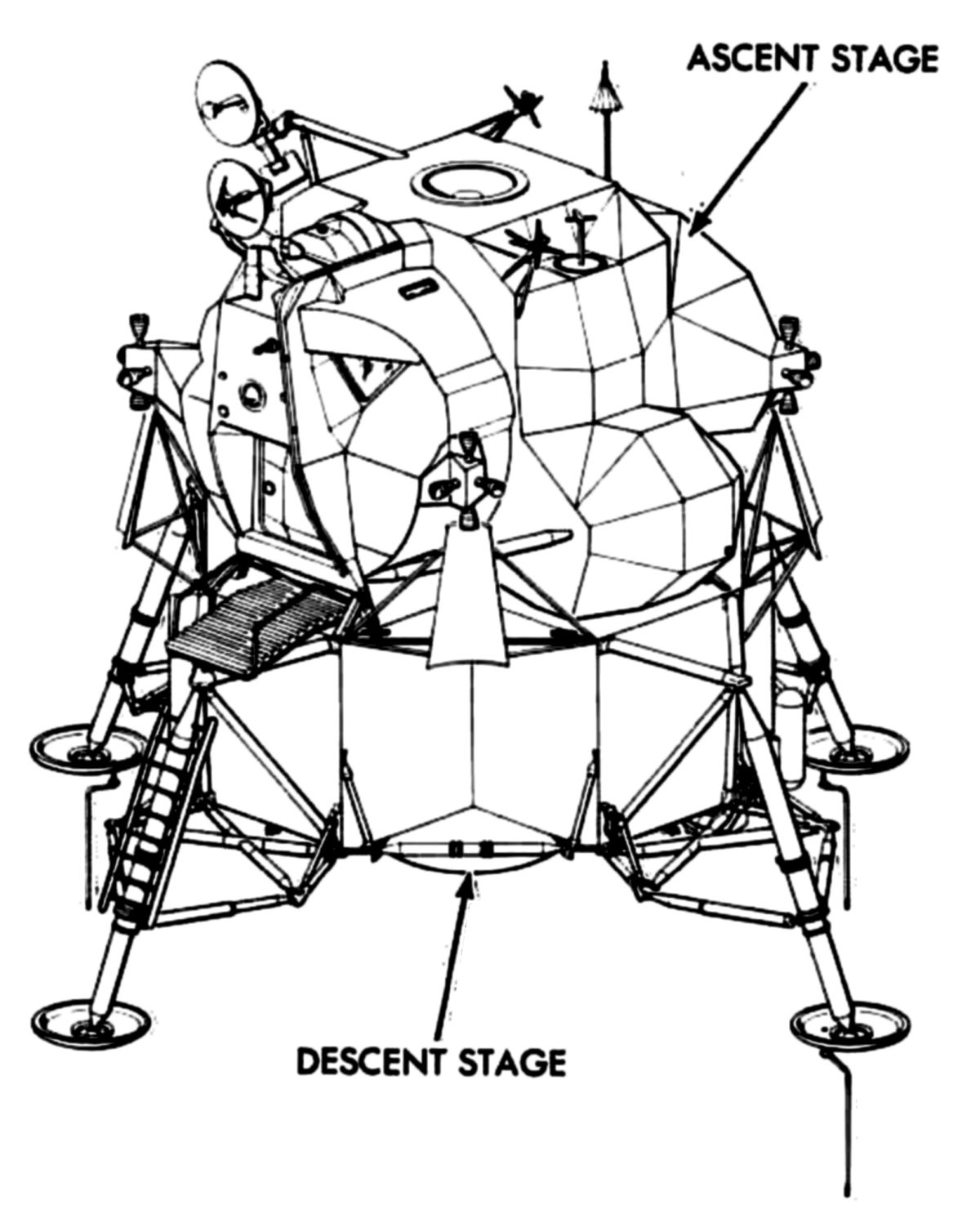 |
| The Lunar Module |
The lunar module, which operated in the vacuum of space, had no need for aerodynamic symmetry. Its outer configuration was dictated only by component location and its cabin provided a nearly perfect operating environment for its two astronauts. The LM consisted of an ascent stage and a descent stage. Both stages remained linked together during separation from the CSM, lunar descent, and lunar stay. The descent stage then served as a launching platform for the ascent stage as it exited the lunar landing site. During lunar ascent, rendezvous and docking the ascent stage operated independently. The ascent and descent propulsion systems, along with the reaction control system (RCS), used identical hypergolic fuel (Aerozine 50, a 50-50 mix of hydrazine (N2H4) and unsymmetrical dimethyl hydrazine (H2NN(CH3)2)) and oxidizer (nitrogen tetroxide (N2O4)) combinations mixed at a 1.6:1 weight ratio.
At earth launch, the NASA/Grumman LM was housed within the spacecraft-lunar module adapter (SLA), which had an upper and a lower section. The upper section had deployable panels that were deployed and jettisoned, seperating the CSM from the SLA. After transposition, the CSM docked with the LM. A drogue within the LM, which mated with the CSM docking probe, was installed in the LM docking tunnel, just below the ring. The probe provided initial vehicle soft docking and attenuated impact imposed by CSM and LM contact. After the CSM probe and drogue joined, latches around the CSM docking ring periphery engaged, resulting in a pressure-tight seal and structural continuity. After docking was completed, astronauts connected electrical umbilicals in the CSM/LM tunnel that furnished electrical power to the LM, allowing separation from the SLA.
Pads at the descent stage outrigger apexes mated with the SLA attachment fittings. Tiedown tension straps, which were explosively released, held the pads against the LSA attachment fittings. After the CSM and LM docked, an astronaut in the CSM fired an explosive charge that severed the tiedown straps after which preloaded springs separated the LM and SLA.
The LM, after descending to the lunar surface from lunar orbit, provided a base from which the astronauts explored the landing site and enabled the astronauts to take off from the lunar surface and to rendezvous and dock with the orbiting CSM. The LM ascent and descent stages were joined by four interstage fittings that were explosively severed at staging. Subsystem lines and umbilicals required for subsystem continuity between the stages were either explosively severed or automatically disconnected when the stages separated.
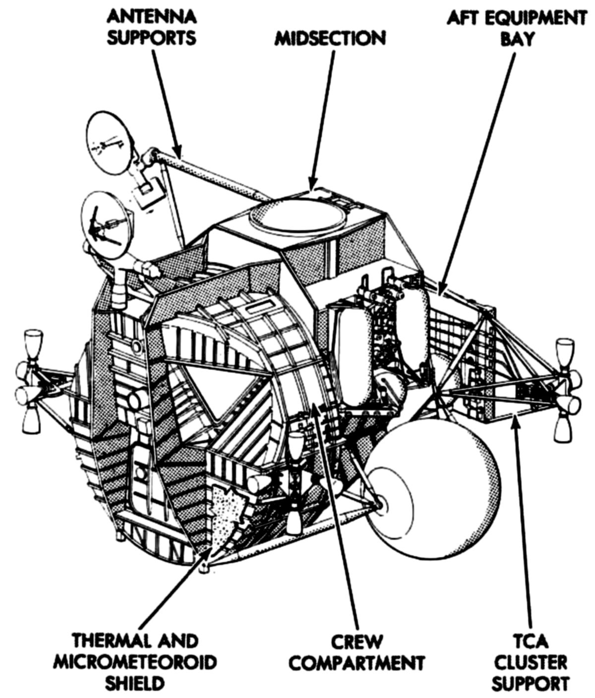
Ascent Stage
The ascent stage consisted of a crew compartment, midsection, and equipment bay. The crew compartment and midsection made up the cabin, which had a 235 ft³ volume, equivalent to a 6.2-foot cube. Its structure was primarily aircraft-style aluminum alloy, with titanium fittings and fasteners. Its skin and web panels were chemically milled to reduce weight. Structural members were fusion welded wherever possible, to minimize cabin leaks and reduce weight. The mechanical fasteners that joined major structural assemblies were sealed with epoxy. The structure, which included reaction control system engine clusters and various antennas, was enveloped by thermal insulation and a micrometeoroid shield.
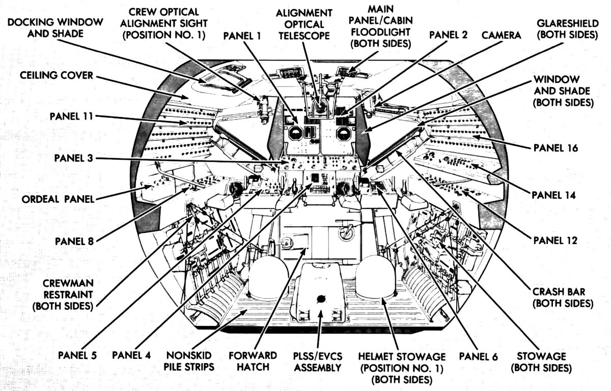
The ascent stage provided a controlled environment for the two astronauts while separated from the CSM, along with sufficient visibility for mission operations. The crew compartment, which occupied the ascent stage front, was cylindrical, with a 92" diameter and a 42" depth. The Commander occupied the left station and the LM Pilot the right. Flight-station centerlines were 44" apart. For maximum downward vision the compartment upper part extended forward of the lower portion. The forward area had control and display panels, body restraints, landing aids, a front window for each astronaut, a docking window above the Commander's station and other accessory equipment. Each flight station had an attitude controller, a thrust/translation controller, and adjustable armrests. There was a hatch in the compartment front face for lunar surface egress/ingress.
A portable life support system (PLSS) donning station was behind the central optical alignment station. S-band and rendezvous radar antennas were attached to the crew compartment exterior. The crew compartment deck measured approximately 36" by 55" and was covered with nonflammable Velcro pile that interfaced with hooked Velcro on the astronauts' boot soles. This helped hold the astronauts to the deck during zero-g flight. Handgrips, aligned with the forward hatch and recessed in the deck, aided ingress and egress.
Control and display panels contained everything necessary to control and monitor subsystem performance. The panel arrangement permitted either astronaut to fly the LM to the CSM. All panels were canted to facilitate viewing. Six of the panels were in front of the flight stations. The upper two panels, one inboard of each flight station, were at eye level. The next two lower panels were centered between the flight stations to enable sharing of control functions. One of the remaining two front panels was in front of each flight station, at waist height. The Commander's panel contained lighting, mission timer, engine, and thrust chamber controls. The LM Pilot's panel had abort guidance subsystem controls. To the left of the Commander's station were three panels: a five-tier circuit breaker panel at the top, an explosive devices and communications audio control panel, and an earth and lunar orbital rate display panel. To LM Pilot's station right, top-to-bottom, were a four-tier circuit breaker panel, electrical power controls and displays, and communications controls and displays. The circuit breaker panels were canted to the line of sight so that the white band on each circuit breaker could be seen when the breakers were open.
The forward hatch was in the front face assembly, just below the lower display panels. The hatch was used for transfer of astronauts and equipment between the LM and lunar surface, or for in-flight extravehicular activity (EVA) while docked with the CSM. The hatch was approximately 32" square and was hinged to swing inboard when opened. A cam latch assembly held the hatch closed and forced a circumferential lip into a preloaded elastomeric silicone seal secured to the LM structure. Cabin pressurization forced the hatch lip further into the seal, ensuring a pressure-tight contact. A latching handle was provided on both sides of the hatch. The hatch could only be opened when the cabin was completely depressurized by opening a cabin relief and dump valve on the hatch. When the cabin was depressurized, the hatch was opened by rotating the latch handle. The cabin relief and dump valve could also be operated from outside the LM. Quick-release pins in the latch plate and hinges could be pulled from inside the LM to open the hatch in an emergency.
The two triangular windows in the front face assembly each had a two ft² viewing area. They were canted down and sideways to permit adequate peripheral and downward visibility. The docking window above the Commander's flight station had approximately 80 in² of viewing area and provided docking visibility. All three windows consisted of two separated panes, vented to space. The outer pane was of low-strength, annealed glass that inhibited micrometeoroid penetration. The pane's outer surface was coated with 59 blue-red thermal control layers and metallic oxide to reduce infrared and ultraviolet light transmission. The outer pane inner surfaces had a high-efficiency antireflective metallic oxide coating that reduced the window mirror effect and increased their light-transmission efficiency. Each window's inner pane of was of chemically tempered, high-strength structural glass. The front window inner panes had a seal between it and the window frame and was bolted to the frame through a metal retainer; the docking window had two seals. The inner pane had the high-efficiency antireflective coating on its inner surface and a defogging coating on its outer surface. All three windows were electrically heated to prevent fogging. The window temperature was not monitored. Heater operation directly affected crew visibility, so proper operation was visually determined by the astronauts. A window shade, with an antireflective coating on its outboard side, was provided for each window. Normally, the shade was rolled up at the window edge. A glare shield mounted between each front window and the control and flight display panels reduced window reflection of internal panel lighting.
Equipment Stowage
Underneath the control end display panels to the right of the LM Pilot's station was a compartmented cabinet. Equipment used during the mission was stowed in this cabinet. This equipment includes food, personal hygiene items, EVA waist tethers, a camera, camera lens filters, a spare light bulb, and a multipurpose special tool having a modified Allen-head. A similar cabinet to the left of the Commander's station contained a spare Environmental Control Subsystem (ECS) lithium hydroxide canister, waste collection containers, a PLSS lithium hydroxide cartridge, and a PLSS condensate container.
 |
 |
 |
 |
| Structure | Crew Compartment Front | Crew Compartment Midsection | Thermal Blanket and Micrometeoroid Shield |
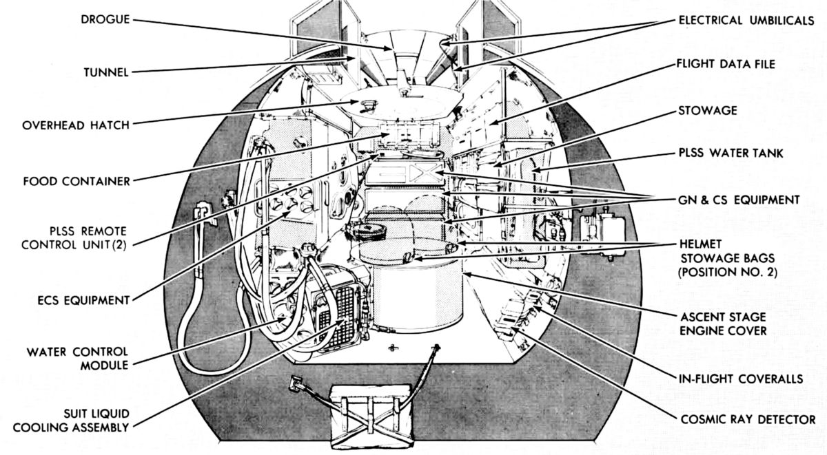
Midsection
From the flight stations the astronauts had an 18" step up into the midsection, which was immediately aft of the crew compartment. Normally, the midsection was not manned; it was traversed by the astronauts upon entering and exiting the LM after docking. The midsection was 54" deep and about 60" high. The internal shape was elliptical, with a minor axis of approximately 56". The midsection housed the ascent engine, part of which protruded up through the lower deck. ECS components, a water-dispensing fire extinguisher, a container for lunar samples, and life support and communications umbilicals were installed on the right side of the midsection. Along the left side were the waste management system and an oxygen purge system, along with stowage for food, lunar overshoes, a pilot's reference kit, and miscellaneous containers. Components of the electrical power subsystem (EPS) and the guidance, navigation, and control subsystem (GN&CS) were mounted on the aft bulkhead. A cylindrical cover protected the accessories section from the engine protrusion. The cover was also used as an astronaut rest position and as a platform for initially observing the lunar surface through the overhead (docking) hatch. Above the hatch was a docking tunnel; directly forward of the hatch, PLSS fittings were mounted. These fittings aided the astronauts in donning their PLSS units.
Midsection construction was similar to the crew compartment, but the midsection had a bulkhead at each end. The aft bulkhead supported the aft equipment bay structure. In addition to the lower deck to which the ascent engine was mounted, there were two others, one supporting the overhead hatch and the lower end of the docking tunnel, the other supporting the upper end of the docking tunnel and absorbing some docking-imposed stress. All decks were made of integrally stiffened machined aluminum alloy, or reinforced chemically milled web. The exterior structure formed a cradle around the midsection to absorb or transmit all stress loads applied to the ascent stage. Stress loads applied to beams atop the crew compartment were transmitted through midsection beams, to the aft bulkhead and, in turn, to the interstage fittings. The external structure, along the sides of the midsection, supported propellant subsystem storage tanks and S-band steerable and VHF in-flight antennas. The aft midsection bulkhead supported propellant and ECS tanks, an aft equipment rack assembly and two aft reaction control system (RCS) quads. A docking target, used for aligning the LM with the CSM during docking, was mounted on the upper left midsection exterior structure.
The 33" overhead hatch was at the top midsection centerline. When the LM and CSM were docked, the hatch permitted transfer of astronauts and equipment. The astronauts passed head-first through the hatch. Handgrips in the docking tunnel immediately above the hatch aided in crew and equipment transfer. The hatch had an off-center latch was operable from either hatch side. The hatch opened inward by rotating the latch handle 90°. A preloaded elastomeric silicone seal was mounted in the hatch frame structure. When the latch was closed, a lip near the hatch outer circumference entered the seal, ensuring a pressure tight contact. Normal cabin pressurization forced the hatch into its seal. To open the hatch, the cabin had to be depressurized by opening a cabin relief and dump valve, which was within the hatch structure. The valve could be operated with a handle on either hatch side.
The docking tunnel, immediately above the overhead hatch, provided a structural interface between the LM and the CSM to permit transfer of equipment and astronauts without exposure to space environment. The tunnel diameter was 32" and it was 16" long. A ring at the tunnel top was compatible with the CSM docking ring, which had automatic clamping latches. The ring was concentric with the nominal ascent and descent engine thrust centerlines. The drogue, a portion of the docking mechanism, was secured below the ring to three mounts in the LM tunnel so that it can mate with the CSM docking probe. When the CSM and LM were docked, the rings were joined, ensuring structural continuity for transmitting midcourse correction and lunar orbit injection stresses throughout vehicle structure.
Aft Equipment Bay
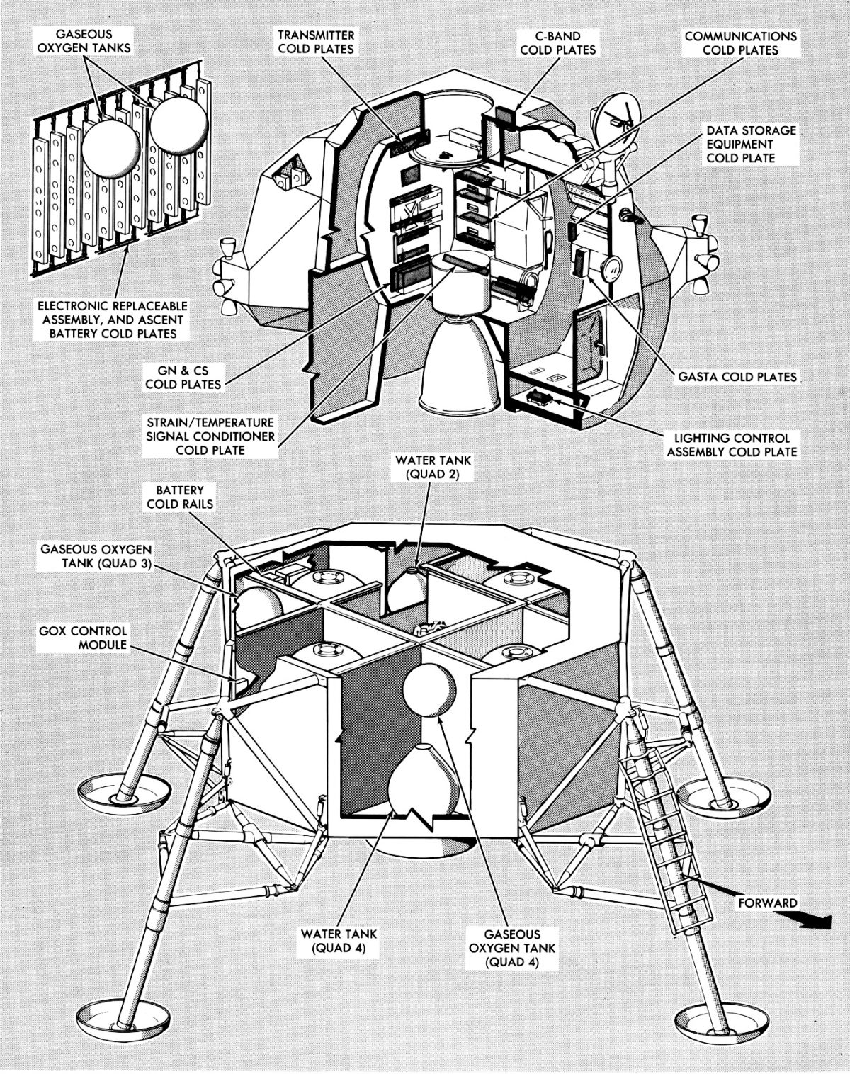
The unpressurized aft equipment bay was formed by the aft midsection bulkhead and the equipment rack, which was cantilevered approximately 33" aft of the bulkhead. The equipment rack had integral cold rails that transferred electronic and electrical equipment (components of the GN&CS, EPS, and Communications Subsystems) heat to the rack. The cold rails were mounted vertically in the rack structural frame. Water-glycol flowed through the cold rails. Two gaseous oxygen tanks and two gaseous helium tanks were secured to truss members between the midsection aft bulkhead and the equipment rack. ECS and main propulsion subsystem components that did not require a pressurized environment or astronaut access were mounted to the aft bulkhead outboard side. The equipment rack and the aft bulkhead supported the aft RCS thrust quads.
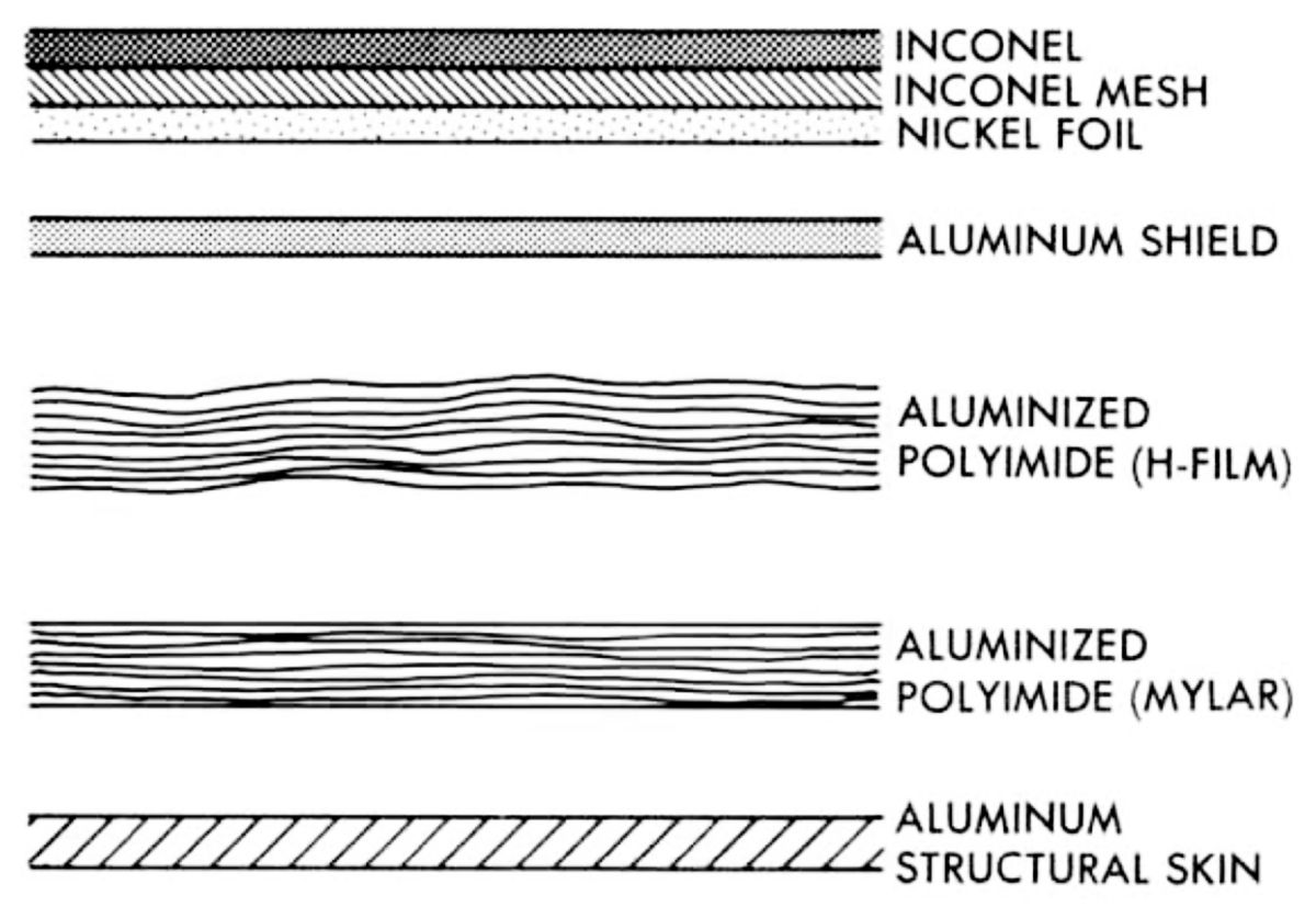
Thermal and Micrometeoroid Shield
After the LM was removed from the SLA it was exposed to micrometeoroids and solar radiation. Active and passive thermal control protected the LM, astronauts and equipment from temperature extremes. Active thermal control was provided by the ECS. Passive thermal control isolated the vehicle interior structure and equipment from its external environment to sustain acceptable temperature limits throughout the lunar mission. The entire ascent stage structure was enclosed within a thermal blanket and a micrometeoroid shield. Glass fiber standoffs of low thermal conductivity held the blanket away from the structural skin. Aluminum frames around the propellant tanks prevented contact between tanks and blanket. The thermal blanket consisted of at least 25 layers of aluminized sheet (Mylar or H film). H film, later known as Kapton, is a specialized polyimide film resistant to temperature extremes but heavier than Mylar. Each layer was only 0.00015" thick and was coated on one side with aluminum. To make an even more effective insulation, the polyimide sheets were hand crinkled before blanket fabrication. This crinkling provided a path for venting, and minimized contact conductance between the layers. Structures with a high thermal conductivity, such a antenna supports and landing gear members, that passed through the thermal blanket also had thermal protection. Individual blanket layers were overlapped and sealed with a continuous strip of H film tape. To join the multilayered sections, blanket edges were secured with grommet type fasteners, then the seam was folded and sealed with a continuous strip of tape. Mylar sheets were used predominantly in those areas where temperatures did not exceed 300°F. In areas where higher temperatures were sustained, additional layers of H film were added to the Mylar sheets. H film can withstand temperatures up to 1000°F, but because it was a heavier material, it was used only where absolutely necessary. Certain areas of the ascent stage were subjected to temperatures as high as 1,800°F due to CSM and LM RCS plume impingement. These areas were thermally controlled by a sandwich of thin nickel foil (0.0005") interleaved with Inconel wire mesh and Inconel sheet, Finally, the highly reflective front and docking window shade surfaces reduced heat absorption. The micrometeoroid shield outboard of the thermal blanket was a sheet of aluminum that varied in thickness from 0.004" to 0.008", depending on micrometeoroid-penetration vulnerability. It was attached to the same standoffs as the thermal blankets. Various thermal control coatings were applied to the outer surface of the shield to provide an additional temperature boundary for vehicle insulation against space environment.
Descent Stage
 |
| LM Descent Stage Structure |
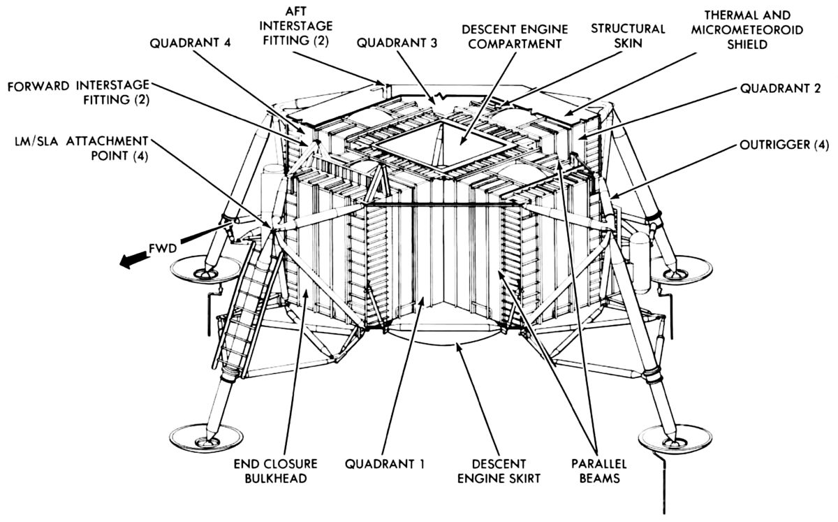
The unmanned LM descent stage accounted for about two-thirds of the LM weight at launch. This was because the descent engine was larger than the ascent engine and it required a much larger propellant load. Its higher weight also resulted from its ascent stage support, landing gear. LM support within the SLA, and support of scientific, communication and transportation equipment for lunar surface use.
Two parallel beam pairs arranged in a cruciform, along with upper and lower decks approximately 85" apart, comprised the descent stage structure. The beam ends about 81" from center were closed off by aluminum beams to provide five equally sized compartments: center, forward, aft, right and left. A four-legged truss outrigger at the end of each beam pair supported the LM in the SLA and the landing gear primary strut. Two of the four ascent stage interstage attachment fittings were mounted on the forward compartment beams; the other two fittings were on the side compartment aft beam. The center compartment housed the descent engine, while fuel and oxidizer tanks were in the remaining compartments. Struts between all main beam ends formed triangular quadrants to give the descent stage its octagonal shape. The quadrants were designated 1 through 4, beginning at the forward compartment left side and continuing counterclockwise (as viewed from the top) around the center. Quad No. 4 housed the modularized equipment stowage assembly (MESA), which consisted of television equipment, lunar sample stowage, and PLSS components. The quad No. 3 contained the lunar roving vehicle (LRV) and the Lunar Retro-Ranging Reflector. Four plume deflectors, which kept the downward-firing RCS thrusters plumes from impinging upon the descent stage, were truss-mounted to the descent stage.
The entire descent stage structure was enveloped in a thermal and micrometeoroid shield similar to that used on the ascent stage. Because the descent stage top deck and side panels were subject to engine exhaust, these areas were extensively protected with a nickel inconel mesh sandwich outboard of the Mylar and H film blankets. A Teflon coated titanium blast shield that deflected the ascent engine exhaust out of and away from the descent engine compartment was secured to the upper compartment side below the thermal blanket. The engine compartment and descent stage bottom were subjected to temperatures in excess of 1,800°F when the descent engine was fired. A special base heat shield protected the descent stage structure and internal components. It consisted of a titanium shield attached to descent stage structure. The heat shield supported a thermal blanket on each of its sides. The thermal blanket that faced the engine nozzle consisted of multiple nickel foil and glass wool layers with an outer H film layer. This blanket acted as a protective membrane to withstand engine exhaust gas back pressures at lunar touchdown and prevented heat, absorbed by the lunar surface during LM landing, from radiating back into the descent stage. Twenty-five layers of H film comprised the blanket. A flange-like ring of columbium backed with a fibrous (Min-K) insulation was attached directly to the engine nozzle extension and joined the base heat shield via an annular bellows of 25-layer H film layers. This bellows arrangement permitted descent engine gimbaling but prevented engine heat from leaking into the engine compartment.
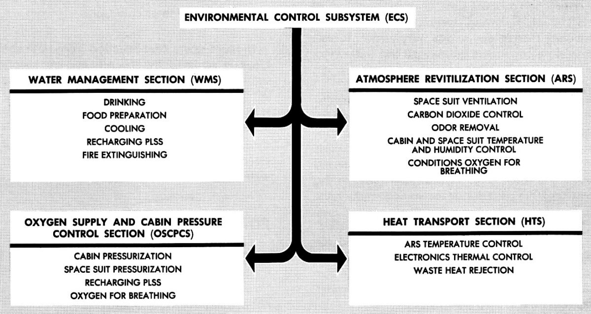
Environmental Control Subsystem (ECS)
 |
 |
 |
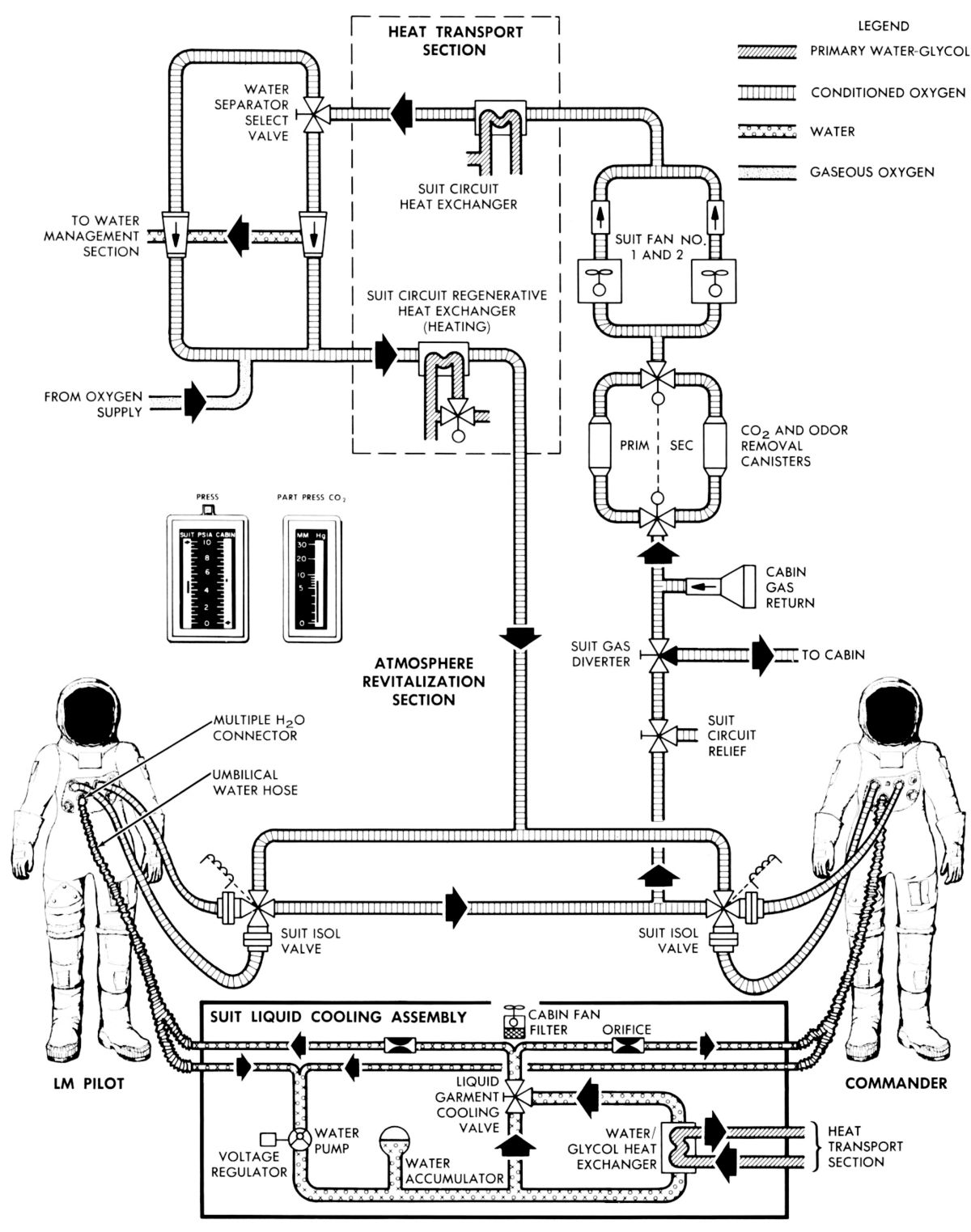 |
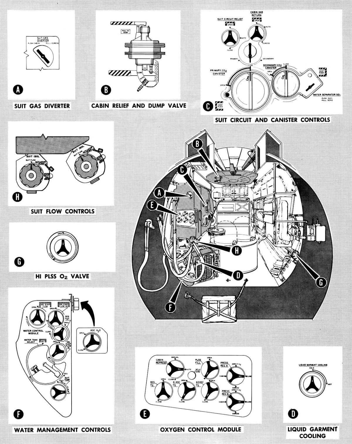
| Block Diagram | Component Location (1) | Component Location (2) | Atmospheric Revitalization Flow Diagram |
 |
 |
 |
 |
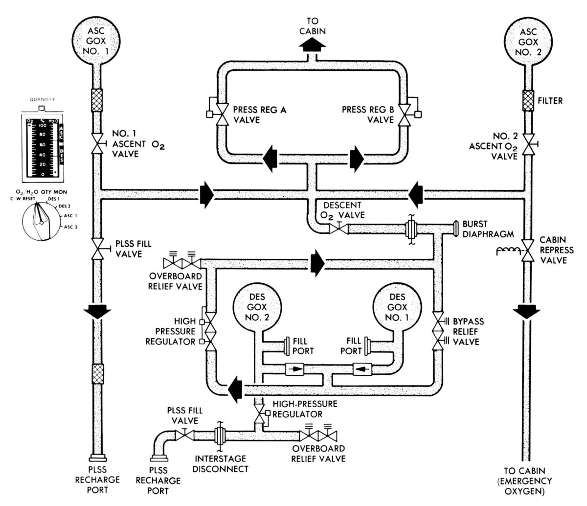
| Oxygen Supply Cabin Pressure Flow Diagram |
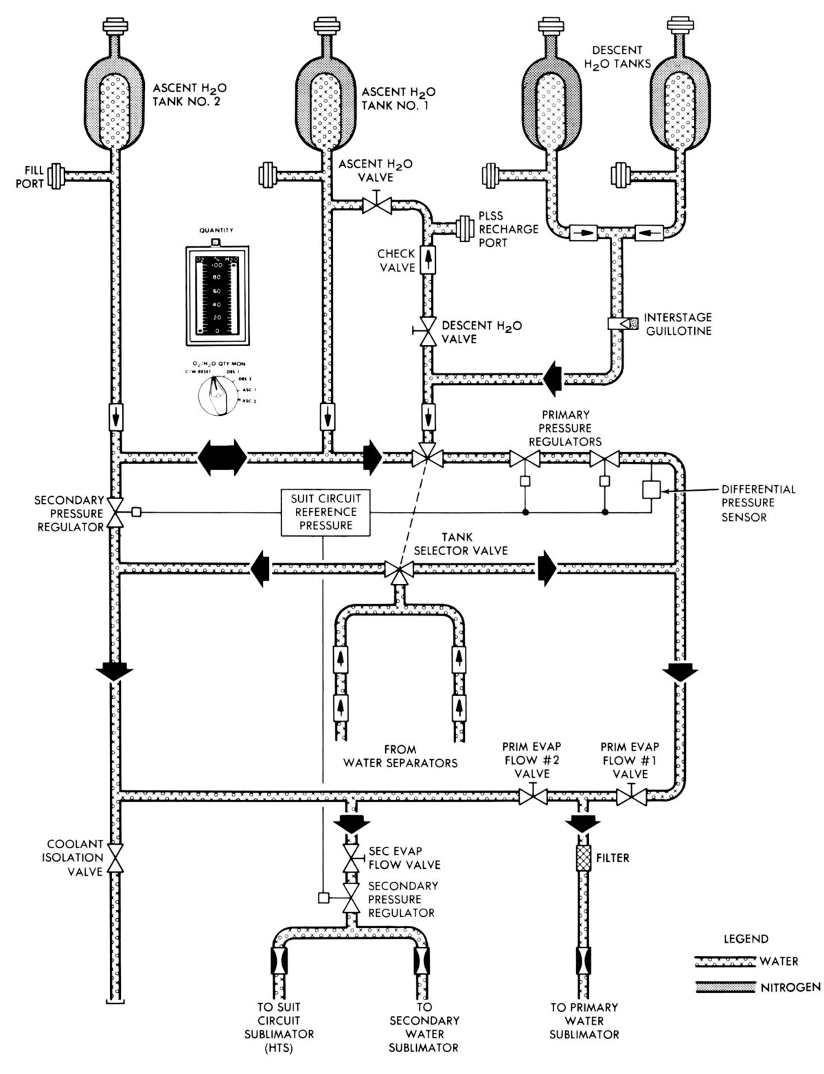
Water Management Flow Diagram |
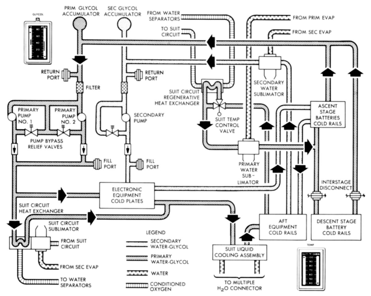
Heat Transport Flow Diagram |
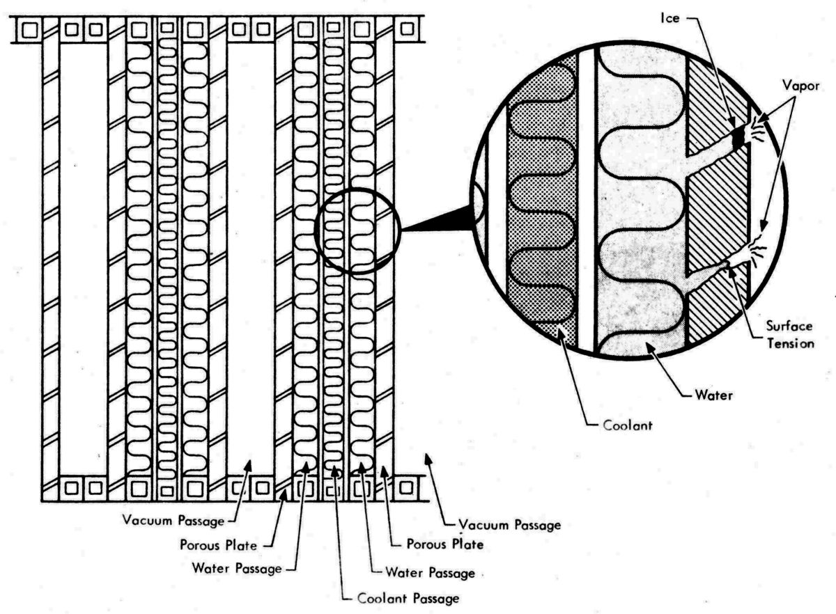
Sublimator Cross Section |
The HTS sublimators, unlike heat exchangers, moved excess heat out of the LM rather than just transferring it to another medium. Water under pressure entered the sublimator and flowed into pores in the porous plate. As the water in the pores encountered the space vacuum at a temperature and pressure below the triple point of water, an ice plug formed in each pore at the outer water surface and continued to build back toward the water passage. As heat was transferred from the coolant, through the water passage and ice layer, the outer surface sublimed (changed state from a solid directly to a gas). As the heat level increased, the ice sublimed at a faster rate, increasing the water flow rate. The converse was also true. The sublimator had an advantage over a heat exchanger because the water flow was self-regulating; as the heat flux decreased, ice plugs formed in the pores decreasing the water flow. Sublimators were also smaller and lighter than the surface radiators used in the SM ECS.
Electrical Power Subsystem (EPS)
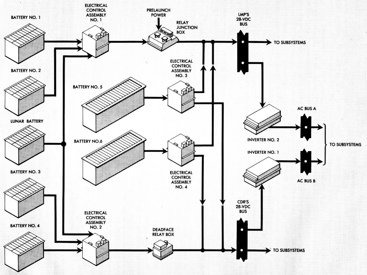 |
| EPS Block Diagram |
The EPS supplied LM electrical power using seven silver-zinc batteries, five in the descent stage and two in the ascent stage. The batteries furnished current for the EPS DC section and two solid-state inverters for the AC section. Both sections supplied operating power to respective electrical buses, which powered all LM subsystems through circuit breakers. Other batteries furnished power that triggered explosive devices, operated the portable life support system, and operated scientific equipment.
The descent stage batteries powered the LM from T-30 minutes until the docked mission phases, at which time the LM received electrical power from the CSM. After separation from the CSM, during the powered descent mission phase, the descent stage batteries were paralleled with the ascent stage batteries, which ensured the minimum required voltage for all possible LM operations. Before lunar surface liftoff the ascent stage battery power was enabled, descent battery power was terminated, and descent battery feeder lines were deadfaced (depowered before physical disconnection) and severed. Ascent stage battery power was then used until after final docking and astronaut transfer to the CM. The batteries were controlled and protected by electrical control assemblies, a relay junction box, and a deadface relay box, in conjunction with the control and display panel.
In addition to being the primary source of LM electrical power, the EPS distributed externally-generated power during prelaunch and docked operations. Prelaunch DC and AC power was initially supplied from external ground power supplies until approximately T-7 hours. At this time, the vehicle ground power supply unit was removed and DC power from the launch umbilical tower was connected. From launch until LM-CSM transition and docking, the EPS distributed internally generated DC power. After docking, LM power was shut down and the CSM supplied DC power to the LM. Before LM-CSM separation, all LM internally-supplied electrical power was restored.
Functional Description
Outputs from the five descent stage batteries and two ascent stage batteries were applied to four electrical control assemblies. The two descent stage electrical control assemblies provided an independent control circuit for each descent battery. The two ascent stage electrical control assemblies provided four independent battery control circuits, two control circuits for each ascent battery. The electrical control assembly monitored reverse current, over-current, and over temperature within each battery. Each battery control circuit could detect a bus or feeder short. If an over-current condition occurred in a descent or ascent battery, the control circuit operated a main feed contactor associated with the malfunctioning battery to remove the battery from the distribution system.
Ascent and descent battery main power feeders were routed through circuit breakers to the DC buses. From these buses, power was distributed through circuit breakers to all LM subsystems, The two inverters that made up the AC section power source were connected to either of two AC buses. Either inverter, when selected, could supply the LM AC requirements.
Astronauts monitored the primary AC and DC voltage levels, DC current levels, and the status of all main power feeders. The electrical power control and indicator panel in the cabin had talkbacks that indicated main power feeder status, indicators that displayed battery and bus voltages and currents, and component caution lights, which were used to detect low bus voltages, out-of-limit AC bus frequencies, and battery malfunctions. Backup AC and DC power permitted the astronauts to disconnect, substitute, or reconnect batteries, feeder lines, buses, or inverters to assure a continuous electrical supply.
Equipment
The ascent and descent stage batteries were made by the Eagle-Picher Company of Joplin, Missouri. Each of the five identical descent stage batteries was composed of silver-zinc plates with a potassium hydroxide electrolyte. Each battery had 20 cells, weighed 155 lb, and had a 415-Ah capacity. Normally, the descent stage batteries were paralleled so that they discharge equally. The batteries could operate in a vacuum while cooled by the ECS cold rail assembly to which the battery heat sink surface was mounted. Five thermal sensors monitored cell temperature limits (+145.5° F) within each battery and illumined a caution light to indicate a battery over-temperature condition. The batteries initially had high-voltage characteristics; a low-voltage tap was provided at the 17th cell for use from T-30 minutes through transposition and docking. The high-voltage tap was used for all other normal LM operations. If one descent stage battery failed, the remaining descent stage batteries could provide sufficient power.
The two identical silver-zinc batteries resided in the ascent stage. Each battery weighed 125 lb, and had a 296 Ah capacity. To provide independent battery systems, the batteries were normally not paralleled during the mission ascent phase. The batteries could operate in a vacuum while cooled by ECS cold rails to which the battery heat sink surface was mounted. The nominal operating temperature of the batteries was about +80° F. Battery temperature in excess of +145° ±5°F closed a thermal sensor, illuminating a caution light that reminded the crew to disconnect the faulty battery. The batteries ordinarily supplied the DC power requirements, from normal staging to final ascent stage docking with the orbiting CSM or during any malfunction that required separation of the ascent and descent stages. If one ascent stage battery failed, the remaining battery supplied sufficient power to accomplish safe rendezvous and CSM docking.
The two descent stage electrical control assemblies managed the descent stage batteries. Each assembly had a control circuit for each battery. A battery control circuit failure did not affect the redundant set. The assembly protective circuits automatically disconnected a descent stage battery if an over-current condition occurred and caused a caution light illumination if a battery over-current, reverse-current, or over-temperature condition was detected. The major elements of each assembly were high- and low-voltage main feed contactors, current monitors, over-current relays, reverse-current relays, and power supplies. An auxiliary relay supplied system logic contact closures to other control assemblies in the LM power distribution system.
The reverse-current relay caused a caution to illuminate when current flowed opposite to normal current flow for at least four seconds. Unlike the over-current relay, the reverse-current relay did not open the related main feed contactor and was self-resetting when the current monitor ceased to detect a reverse-current condition. During reverse-current conditions, the related contactor had to be manually switched open. The control assembly power supplies provided AC for current-monitor excitation and regulated DC for the other circuits.
The two ascent stage electrical control assemblies individually controlled and protected the two ascent stage batteries. Each assembly contained electrical power feed contactors, an over-current relay, a reverse-current relay, and a current monitor. Each ascent stage battery could be connected to its normal or backup main feeder line via the normal or the backup main feed contactor in its respective assembly. Both batteries were therefore connected to the primary DC power buses. The normal feeder line had over-current protection; the backup feeder line did not.
The relay junction box controlled the low-voltage contactors of batteries 1 and 4 (on and off) from the launch umbilical tower and CSM, and all low- and high-voltage descent power contactors (off) on receipt of an abort stage command. The junction box included abort logic relays, which, when energized by an abort stage command, close the ascent stage battery main feed contactors and open the deadface main feed contactors and deadface relays. The deadface relay was manually opened and closed or automatically opened when the abort logic relays closed. The deadface relay in the junction box disconnected half of the main power feeders between the descent and ascent stages; the other half of the power feeders was deadfaced by the deadface relay in the deadface relay box. The ascent stage then provides primary DC power to the LM.
The deadface relay box disconnected those power feeders that were not controlled by the relay junction box, in the same manner as the relay junction box. Two individual deadfacing facilities (28 volts for each circuit breaker panel) were provided.
Two identical redundant 400-Hz inverters individually supplied the primary LM AC power. Inverter outputs were derived from a 28 VDC input. The inverter stage output was controlled by 400-Hz pulse drives developed from a 5.4 KHz oscillator, which was, in turn, synchronized by timing pulses from the Instrumentation Subsystem. An electronic tap changer sequentially selected a tapped transformer output in the inverter stage, converting the 400-Hz square wave to an approximate sine wave of the same frequency. A voltage regulator maintained the inverter output at 115 VAC during normal load conditions by controlling the DC-to-DC converter output amplitude . The voltage regulator also compensated for DC input and AC output load variations. When a bus voltage was less than 112 VAC or the frequency was < 398 Hz or > 402 Hz, a caution light went on, but went off when the malfunction was remedied.
All primary LM AC and DC power circuits were protected by circuit breakers on the Commander's and LM Pilot's buses. Two DC buses were electrically connected by the main power feeder network. Functionally redundant LM equipment was placed on both DC buses (one on each bus), so that each bus could individually perform a mission abort.
Two sensor power fuse assemblies in the aft equipment bay provided a secondary DC bus system that supplied subsystem excitation to transducers that developed display and telemetry data. During prelaunch procedures, primary power was supplied to the assemblies from the Commander's 28-VDC bus. Before launch, power from the launch umbilical tower was disconnected, and power was subsequently available to the sensor power fuse assemblies from the LM Pilot's 28-volt DC bus. Each assembly comprised a positive DC bus, negative return bus, and 40 A fuses. All sensor return lines were routed to a common ground bus.
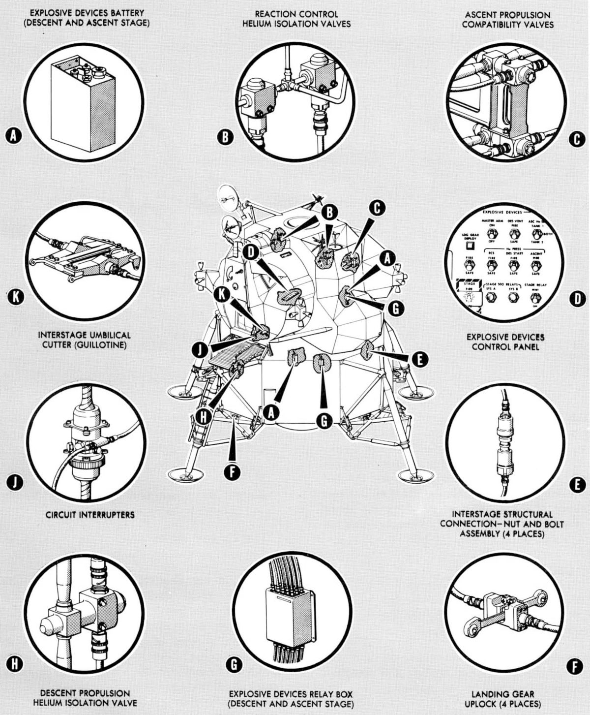
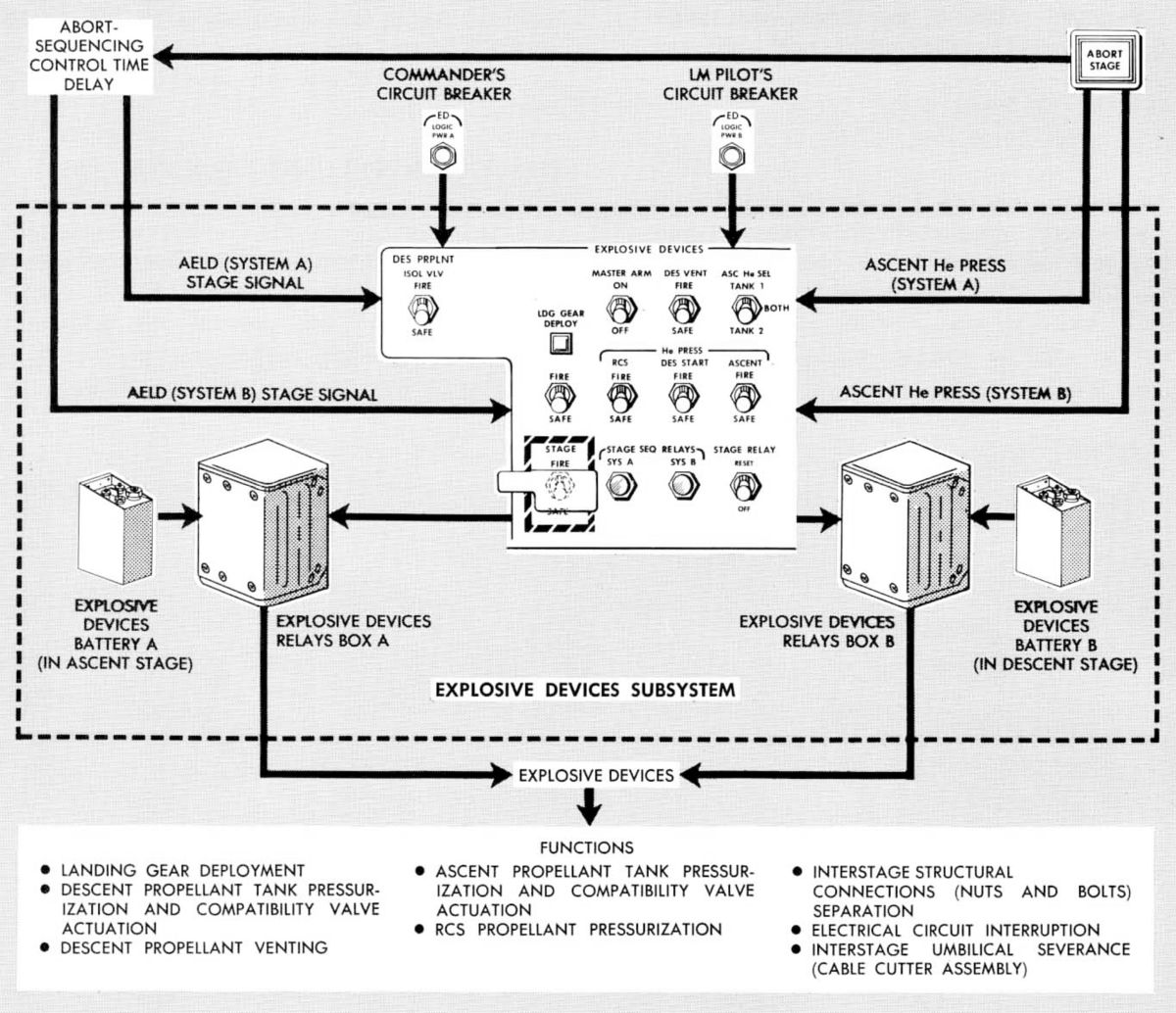
Explosive Devices
Electro-chemical explosive devices were operated by the astronauts to pressurize the propellant tanks, separate the ascent and descent stages, vent the descent propellant tank after landing, and deploy the landing gear. The LM had two types of explosive devices: these consisting of detonator cartridges containing high-explosive charges of high yield and pressure cartridges containing propellant charges of relatively low yield. An electrical signal, originated by an astronaut operating LM control switches, triggered an initiator that fired the cartridges.
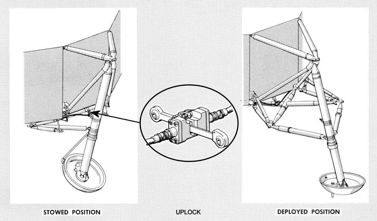
Landing Gear Deployment — Each of the four landing gear assemblies was restrained in the stowed position by an uplock assembly that contained two detonator cartridges. While the LM was docked with the CSM in lunar orbit, the LM Commander deploy the landing gear by firing both detonator cartridges in each uplock. When all four landing gear assemblies had been deployed, a landing gear deployment indicator flag on the LM control panel turned gray.
Reaction Control Subsystem Propellant Tank Pressurization — RCS fuel and oxidizer tanks were pressurized immediately before landing gear deployment when the LM Commander fired two cartridges that opened dual, parallel helium isolation valves. The LM and CSM could then be separated.
Descent Propellant Tank Pressurization — After the LM and CM separated, the astronauts pressurized descent propellant tanks. The Commander fired the compatibility valve cartridges, explosively opening the valves. He then fired cartridges to explosively open the ambient helium isolation valve. After the descent engine was started, the cryogenic helium flowed freely to the descent engine fuel and oxidizer tanks, pressurizing them. The descent engine could then be started.
Descent Propellant Tank Venting — After lunar landing, the Commander simultaneously opened two explosive vent valves to depressurize the descent propellant tanks. This protected the astronauts, when outside the LM, against untimely tank venting through the relief valves.
Ascent Propellant Tank Pressurization — After the lunar stay, the astronauts took off from the lunar surface in the ascent stage. This required ascent stage propellant tank pressurization shortly before the ascent engine was started. To accomplish pressurization, the Commander fired explosive valve cartridges, which simultaneously opened helium isolation valves and fuel and oxidizer compatibility valves. This permitted helium to pressurize the ascent fuel and oxidizer tanks.
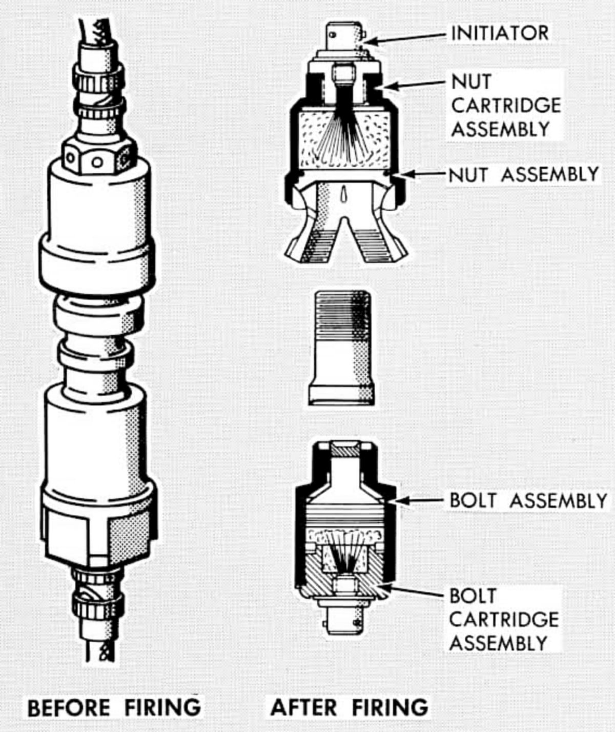
Stage Separation — The ascent and descent stages were separated immediately before lunar lift-off, or in the event of mission abort the Commander set control switches to initiate a controlled sequence of stage separation. First, all signal and electrical power between the two stages was terminated by explosive circuit interrupters. Next, explosive nuts and bolts joining the stages were ignited. Finally, an explosive cable-cutter guillotine automatically severed all wires, cables, and water lines connected between the stages. Stage separation completed, operation of the ascent engine could propel the ascent stage into lunar orbit for rendezvous with the CSM.
 |
 |
 |
 |
 |
| Equipment Location | Block Diagram | Landing Gear Uplock | Nuts and Bolts | Cable Guillotine |
LM Propulsion
Descent Propulsion System
Ascent Propulsion and Reaction Control Systems
References
Apollo Operations Handbook, Block II Spacecraft, Volume 1: Spacecraft Description 5M2A-03-BLOCK II (Houston, Texas: Manned Spacecraft Center, 15 Oct 1969).
Brooks, Courtney G., James M. Grimwood, Loyd S. Swenson, Jr. Chariots for Apollo: A History of Manned Lunar Spacecraft NASA SP-4205 (Washington, DC: NASA, 1979).
Cherne, Jack M. Mechanical Design of the Lunar Module Descent Engine (Redondo Beach, California: TRW Systems, 1967).
Dressler, Gordon A., J. Martin Bauer TRW Pintle Engine Heritage and Performance Characteristics (Redondo Beach, California: TRW Inc., 2000
Fisher, Steven C. and Shamin A. Rahman, eds. Remembering the Giants: Apollo Rocket Propulsion Development (Washington, DC: NASA, 2009).
Hoagland, Richard. Apollo News Reference (Bethpage, New York: Public Affairs, Space, Grumman Aerospace Corporation, 1971).
Humphries, Clarence E. and Reuben E. Taylor Apollo Experience Report — Ascent Propulsion System TN D-7082 (Houston, Texas: NASA Manned Spacecraft Center Mar 1973).
Hammock Jr., William R., Eldon C. Currie and and Arlie E. Fisher. Apollo Experience Report — Descent Propulsion System TN D-7143 (Houston, Texas: NASA Manned Spacecraft Center, Mar 1973).
Interbartolo, Michael Apollo Lunar Module Propulsion Systems Overview JSC-17237-14 (Houston, Texas: NASA Johnson Space Center, 1 Jan 2009).
Lunar Module LM-10 through LM-14 Vehicle Familiarization Manual LMA790-2 (Bethpage, New York: Grumman, 1 Nov 1969).
Vaughan, Chester A., Robert Villemarette, Witalij Karakulko, Donald R. Blevins Apollo Experience Report — Lunar Module Reaction Control System TN D-6740 (Houston, Texas: Manned Spacecraft Center, Mar 1972).
--- On to Part 9.41, The Apollo Lunar Module Descent Propulsion System ---
Send mail to
![]() with questions or comments about this web site.
with questions or comments about this web site.
![]()