U.S. Manned Rocket Propulsion Evolution
Part 8.30: The Saturn S-IVB Stage
Compiled by Kimble D. McCutcheon
Published 1 Aug 2021; Revised 25 Jul 2024
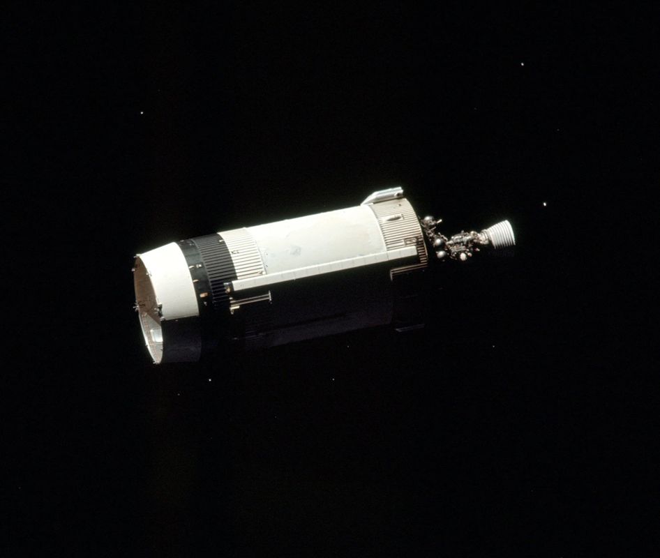
Probably S-IVB-507,
(Apollo 12), Still in Space |
The Saturn S-IVB was the second Saturn IB booster stage and third Saturn V booster stage. While the two versions had much in common, they differed in aft interstage, ullage motor count, and auxiliary propulsion system (APS) details. The Saturn V version is discussed here. Readers interested in Saturn S-IB booster details were invited to review pertinent Chapter 5 of Skylab Saturn IB Flight Manual, MSFC-MAN-206. The S-IVBs single J-2 engine boosted the Apollo spacecraft into a circular earth orbit on the first burn, then boost the spacecraft to lunar intercept trajectory with a second burn. The stage dry weight, including interstage, was about 33,142 lb. Gross weight at ignition was about 262,300 lb.
Because the S-IVB burned twice with an extended coast period between the burns, and because it could be controlled both by the IU and Apollo Command Module, it was far more complicated than the other launch vehicle stages. Propellant tanks had to be pressurized and then repressurized; the APS was added to assist the second burn and keep the pointy end forward during coast periods. |
S-IV and S-IVB Development
The S-IV was originally intended as the fourth stage of a rocket known as C-4, but instead became the Saturn I second stage and Saturn V third stage. In an effort to avoid confusion (?) the S-IV retained its original designation.
As the S-IV was the first contracted Saturn stage, ABMA and NASA leaders carefully crafted preliminary requirements, the procurement process, and invited at least 20 companies to submit proposals. Of the 11 proposals Convair and the Douglas Aircraft Company (DAC) were the top contenders. The contract ultimately went to DAC on 26 May 1960 because Convair already had LH2 work on the Centaur upper stage and NASA did not want LH2 expertise confined to one company. In addition, DAC had designed and produced the PGM-17 Thor IRBM for the U.S. Air Force using a construction similar to its many aircraft designs and has proposed similar construction for the S-IV; NASA thought this would be more durable than Convair's thin-skin inflated structure.
Before the final contract was signed, NASA and DAC refined the requirements, discussed missions, engines and configurations, ultimately deciding on three booster variants. The S-IV would be 18.3 feet in diameter, use six Pratt & Whitney RL10 engines and serve as a Saturn I second stage. The S-IVB would be 21.75 feet in diameter and use a single Rocketdyne J-2; one version, with a straight aft skirt, would serve as the Saturn IB second stage and another, with a tapered aft skirt, as the Saturn V third stage.
The Saturn V S-IVB version was far more complicated than the other launch vehicle stages. Its single J-2 engine had to burn twice – once to achieve a circular earth orbit and a second time to send the Apollo command, service and lunar modules on their collective way to the moon. As much as 4.5 hours could elapse between the two J-2 burns. During this coast period an auxiliary propulsion system (APS) maintained proper vehicle attitude control and settled the propellants against their feed lines prior to engine restart.
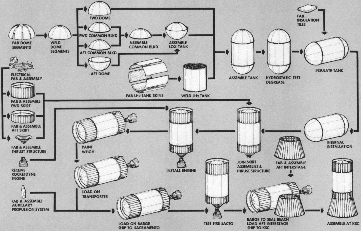
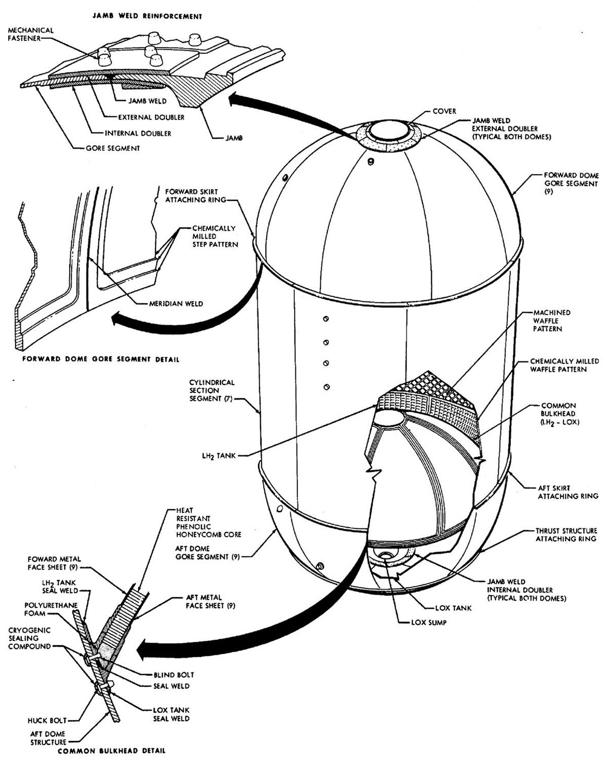
During its Thor missile design and production DAC had chosen 2014 aluminum alloy for propellant tanks and gained considerable experience in its use. Starting with 0.75" thick 2014 sheets, DAC used a Giddings and Lewis mill to form a waffle pattern on the tank segments' inside surfaces, producing recesses that were about 3" square. Technicians then inserted reusable polyethylene blocks into the waffle recesses to prevent the ribs from bucking during progressive forming to a circular form using a Verson power press. Once seven of the skin segments were formed they were welded into tank barrel segments.
The hemispherical domes were built up from nine gores that had been stretch-formed over special dies to accurate contours. Waffle patterns on the gores were chemically milled. Nine gores were then joined using a custom meridian welding jig, forming the tank domes that were then attached to the barrels.
Paleno Blocks |
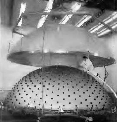
The hemispherical common bulkhead that separated the LOX and LH2 tanks consisted of a three-layer sandwich of 2014 T6 aluminum shells and insulation. The forward shell was only 0.032" thick and the aft shell was 0.055" thick. Such large, thin articles required very careful handling. The aft dome was attached to a bonding fixture. Workers then set 350 small honeycomb Paleno blocks over the surface. Each block had a pad of cellophane-covered putty attached. The forward dome was lowered to its approximate final position, contacting each putty pad. The dome was raised and workers measured the indentation on each pad to map variations in the aft dome contour. The blocks were removed, the honeycomb insulation applied to the aft dome forward face, and using the measurements derived from the Paleno blocks, the insulation surface was milled and sanded to produce a custom fit. Workers then cleaned the insulation surface, bonded it to the forward bulkhead's aft face and cured the assembly at 360°F in an oversized autoclave. Once cured, the common bulkhead edge was machined on a Niles boring mill, an operation that produced the circumferential attach ring.
S-IVB assembly joined the complete LOX tank to the LH2 cylinder, a process that required both inside and outside welding, with the stage in upright and then inverted. Workers positioned the LOX tank in the assembly tower and hung the LH2 cylinder above it. They then heated the LH2 tank base, causing it to slightly expand. The heated LH2 cylinder was lowered over the LOX tank and allowed to cool, forming an interference fit. The assembly was then welded, x-rayed, dye-penetrant checked, and hydrostatic tested.
The flight control system provided S-IVB attitude control via correction signals from the IU. Two linear hydraulic actuator assemblies gimbaled the J-2 engine. Hydraulic pressure was generated by electric and engine-driven pumps, plus an auxiliary pump. The original DAC-designed S-IV actuators were slim and long, like aircraft landing gear actuators. MSFC engineers, relying on past Jupiter experience, insisted that thrust levels and mission environment dictated shorter, thicker actuators. When the DAC actuators developed unacceptable instabilities, DAC contracted with Moog Industries to build actuators to MSFC specifications. In addition to thrust vectoring, these actuators also nulled the J-2 thrust-line angles during liftoff and before ignition. While J-2 actuators handled pitch and yaw, roll control came from the APS.
Insulation
As we learned from the S-II stage discussion, NAA chose to apply LH2 tank insulation panels to the exterior. This approach caused numerous problems with panel adhesion and air liquefaction. The same was true of the Space Launch System (Space Shuttle) external tank, which had continuous trouble with external insulation bonding and even led to the Columbia orbiter loss because an insulation chunk broke away and damaged a leading edge. When DAC began investigating its S-IVB insulation scheme, only the Convair Centaur upper stage was using LH2. The Centaur was a much smaller stage and its external insulation had given considerable trouble. DAC decided to separate the insulation from the tank structure problems. Thus the insulation configuration and material selection could proceed independent of the tank structure.
DAC had numerous worries about external insulation:
- LH2 loading would create severe thermal stress and possibly damage the aluminum tank walls with their high coefficient of thermal expansion.
- External insulation would result in nearly 100% of the tank's capacity boiling off before the tank walls chilled to the -423°F LH2 storage temperature.
- The high LH2 boil-off rate would waste much more expensive propellant and require more robust venting. If the external insulation was damaged exposing the underlying metal, the exposed cold area would pull air into the damage, liquefy it, and form a progressively larger cold area. When aerodynamic heating melted and boiled the liquid air it could rupture the insulation bond and pop off insulation chunks.
- No adhesives were available that would reliably bond insulation to aluminum at cryogenic temperatures.
- External insulation was susceptible to handling and transportation damage as the S-IVB moved through assembly, test and delivery.
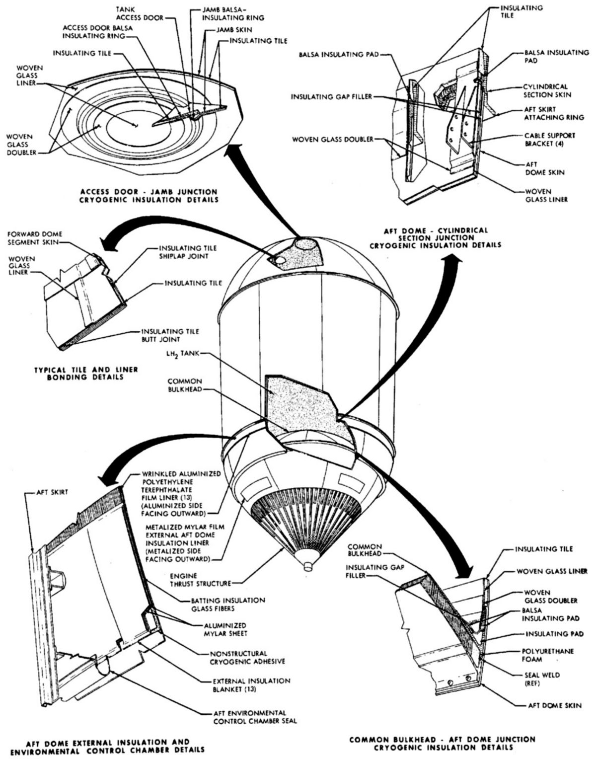
By contrast, internal insulation eliminated nearly all these problems. Its chief disadvantage is that it had to be carefully fitted and applied by hand. Internal insulation dramatically reduced LH2 boil-off loss to around 25%. Even with efficient internal insulation LH2 still had to be replenished before launch at rates approaching 300 gpm. Since the internal insulation prevented contact between the aluminum tank walls and the LH2, the bond between insulation and tank interior was much warmer, allowing the use of existing adhesives.
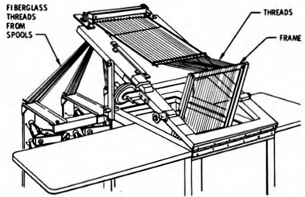
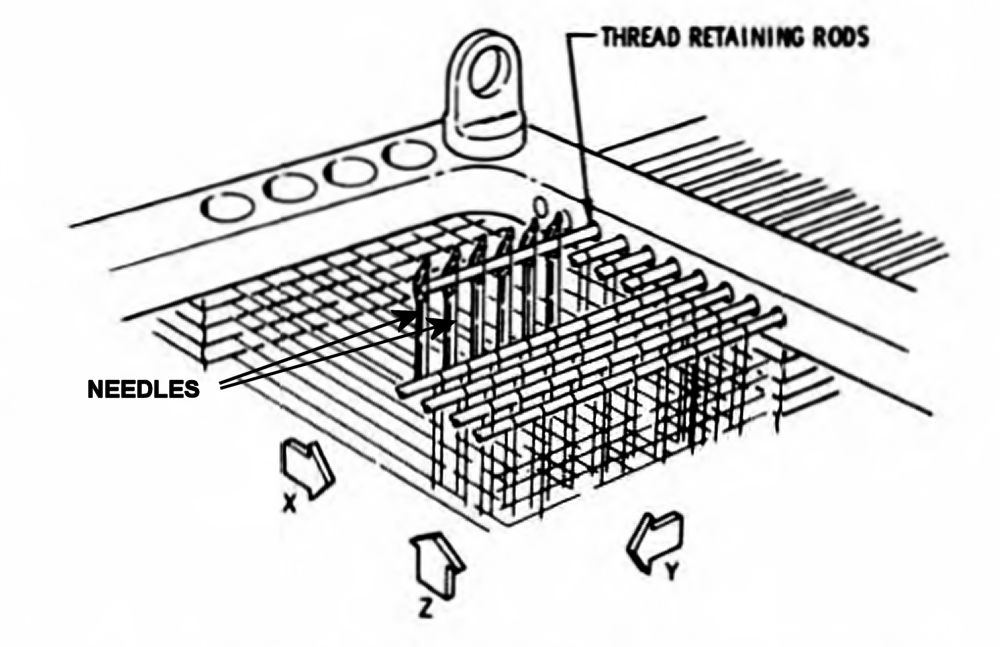
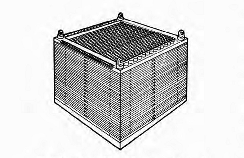
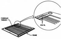
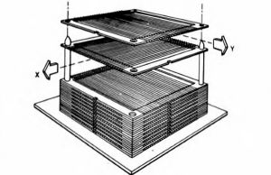
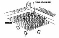
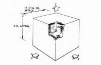
In its search for an effective LH2 tank insulation material DAC seriously considered balsa wood but found that the S-IVB program would use up the world's balsa supply; each S-IVB LH2 tank was 21.75 feet in diameter and 40 feet long, most of which would have to be covered by the internal insulation. DAC tried several iterations of polyurethane-foam-filled fiberglass honeycomb with unsatisfactory results. They ultimately developed a successful synthetic balsa in the form of a foam-filled three-dimensional fiberglass thread matrix. The thread was wound 0.188" apart on special 0.188" thick frames that were then stacked at right angles to one another, forming an X – Y matrix. A custom machine then used special needles to weave the Z-axis by lifting fiberglass threads over 0.188" thread retaining rods. The woven frames were then placed in a mold into which polyurethane foam was poured. The foam cured, producing a 12.5" x 12.5" by 8" block that was subsequently sawed into slices, each of which was machined to match the required interior contour of each waffle pattern recess while maintaining a tab over each waffle rib that contacted adjacent foam tiles. Each of the 4,300-odd insulation tiles was numbered to match its unique position inside the tank. The machining operations left small fiberglass thread ends of sticking out of the tile edges, which improved tile adhesion.
S-IVB LH2 Tank Insulation Production
 |
 |
 |
 |
 |
 |
| Thread Winding |
Thread Frame |
Frame Stack |
Z-Axis Threads |
Frame Assembly |
Insulation Block |

Laying Tile |

Insulation Close-Out |
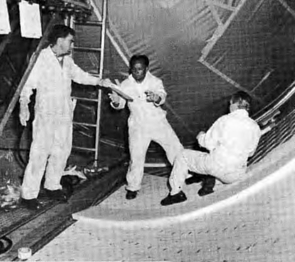
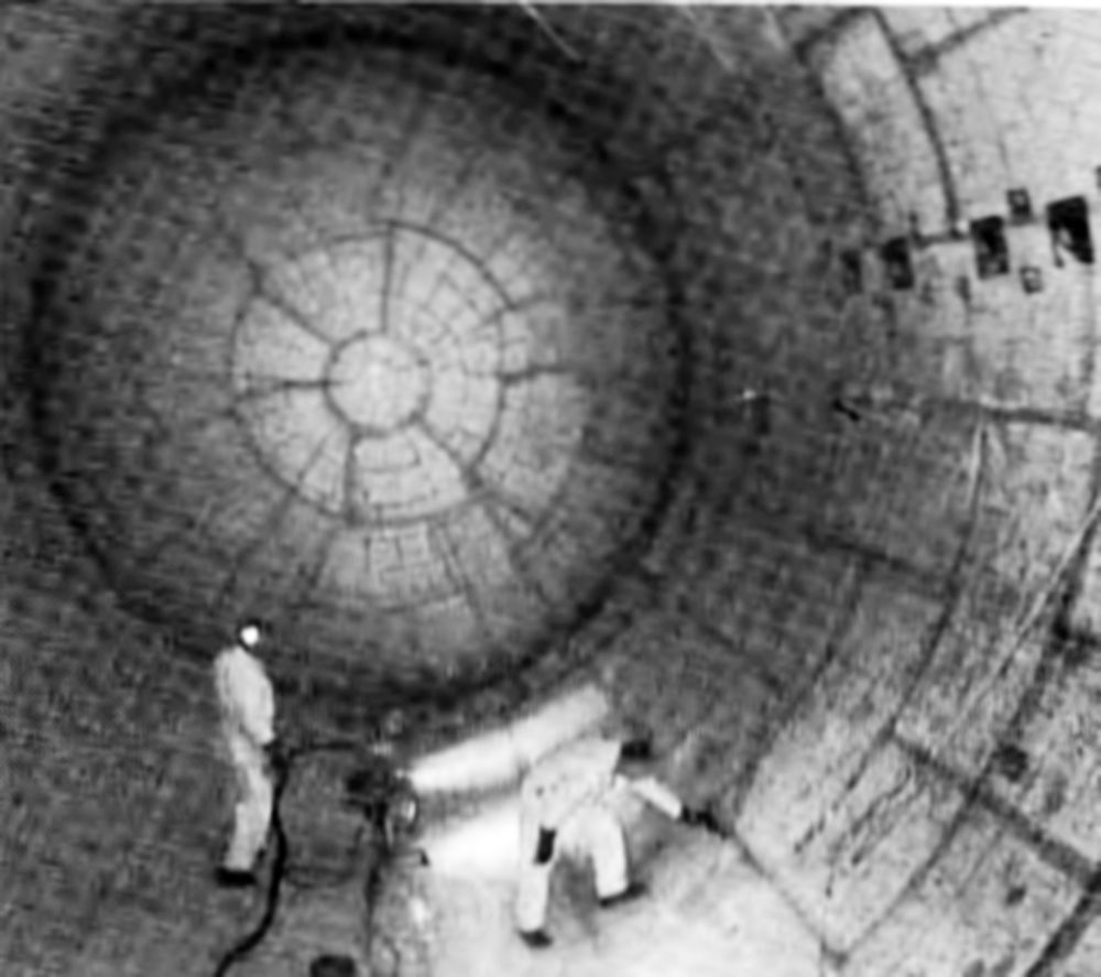
In the environmentally controlled insulation facility work area workers with protective gloves and shoe covers entered the tank through a forward opening and began laying tile aft-to-front, working their way back to the entry point. Adhesive was automatically applied to each tile in an adjoining room and transferred inside the tank via a conveyor to be installed by the numbers. The tank and environment temperature was maintained at 55 – 65°F during this process to extend the adhesive's life. When a section was completely tiled, workers applied a custom fiberglass cloth liner, installed a vacuum bag, and exited the tank. Temperature was then raised to 110°F to cure the adhesive. The tank was then rotated to the next section. When the LH2 tank interior was completely tiled, workers reentered the tank, applied resin-impregnated fiberglass cloth over all the tiles, exited the tank, and subjected it to final 24-hour curing cycle at 160°F. Once the curing process was complete and the tank cooled, workers completed installation of valves, helium bottles, fuel level sensors and other hardware. The tank was degreased, the tank was sealed and hydrostatic-pressure tested.
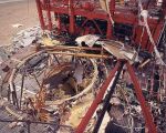
Testing Oopsies
 |
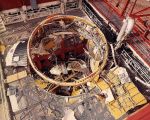 |
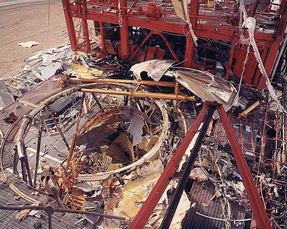
| Destroyed S-IVB-503 in SACTO Beta III Test Stand |
All Saturn stages were subjected to exhaustive quality control procedures and ground testing, which accounted for around 50% of the total manufacturing effort. This is one reason why no the Saturn V launch vehicle was ever lost. But nearly every stage suffered problems during production hydrostatic and firing tests; the S-IVB was no exception.
During one hydrostatic test the sophisticated and complex automated test equipment overpressurized and damaged a tank assembly. After a lengthy investigation, DAC engineers inserted a 140-foot standpipe in the water supply so that if too much water pressure was applied, the excess would rise up the standpipe and simply overflow.
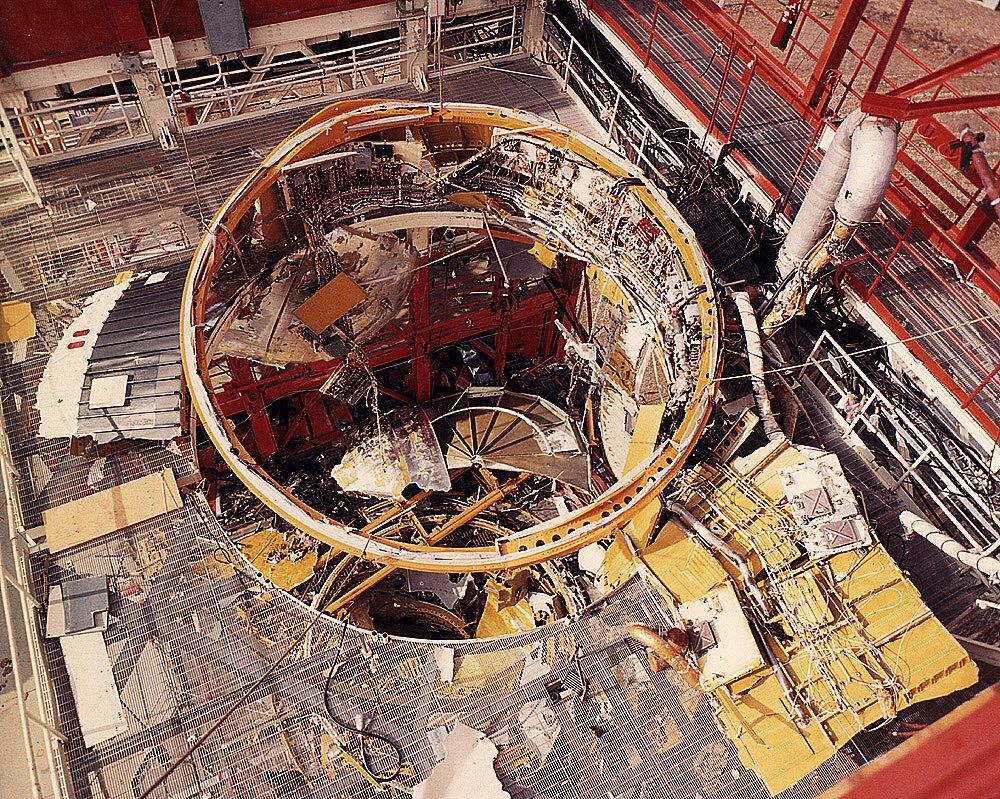
A 20 Jan 1967 S-IVB-503 acceptance test in DAC's Sacramento Test Operations (SACTO) Test Stand Beta III proceeded normally until 11 seconds before ignition when the stage exploded (Video, about 11:35). The stage was blown completely out and away from the test stand, leaving jagged metal hanging in the test stand structure. Nearby structures and windows, along with the Beta II test stand, were damaged. An extensive investigation revealed that one of the eight high-pressure titanium helium storage spheres on the S-IVB thrust structure had exploded, rupturing the LOX and LH2 fill lines, which allowed the fuel and oxidizer to mix and explode. The helium sphere vendor had substituted pure titanium fill wire for the specified fill wire alloy when the helium hemispheres were joined. The resulting weld was weak and failed after a few pressurization cycles. DAC built the remaining helium spheres in-house.
From the start, NASA planners hoped for high-reliability launch operations by using a fully automated checkout, countdown, and launch procedure. DAC developed this automation in parallel with the first production S-IVB and used it for the first time at SATCO on 8 Aug 1965 for the first S-IVB flight stage (AS-201, the two-stage Saturn IB) full-duration acceptance test firing.,
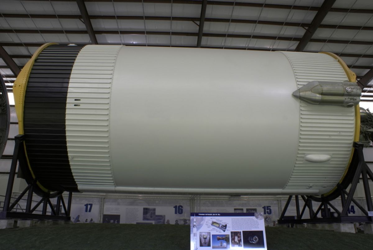
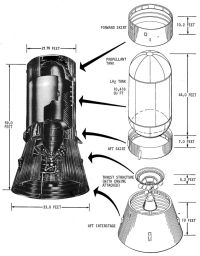
S-IVB Structure
The S-IVB airframe consisted of a forward skirt, propellant tanks, aft skirt, thrust structure, and aft interstage. These assemblies, except for the propellant tanks, were built-up skin-and-stringer aluminum alloy airframe construction. Two longitudinal external tunnels housed wiring, pressurization lines, and propellant dispersion system components. The non-structural tunnel covers were made of aluminum stiffened by internal ribs.
The cylindrical forward skirt extended from the LH2 tank sidewall/forward dome intersection providing hard Instrument Unit (IU) attach points and load support for the IU and Apollo spacecraft. Forward skirt equipment was serviceable via an IU access door. Five environmental plates supported and thermally conditioned electronic components, such as transmitters and signal conditioning modules, which were attached to the skirt interior. The forward umbilical plate, antennae, LH2 tank flight vents and the tunnel fairings were attached externally to the forward skirt.
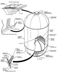
The cylindrical propellant tank featured a hemispherical dome at each end and a common bulkhead separating LOX from LH2. This bulkhead consisted of two parallel hemispherical 2014-T6 aluminum alloy domes bonded to and separated by a fiberglass-phenolic honeycomb core. The LH2 tank internal surface was machine-milled in a waffle pattern, which produced a light, stiff structure. Sealed fiberglass polyurethane insulation blocks were bonded into the waffle pattern milled areas to minimize LH2 boil off.
The tank walls supported and transmitted thrust force to all forward loads. Attached to the LH2 tank interior were a 34-foot-long propellant utilization (PU) probe, nine cold helium spheres, brackets with temperature and level sensors, a chilldown pump, a slosh baffle, a slosh deflector, and fill, pressurization and vent pipes. Attached to the LOX tank interior were slosh baffles, a chilldown pump, a 13.5-foot-long PU probe, temperature and level sensors, and fill, pressurization and vent pipes. The thrust structure forward edge was attached to the LOX tank.
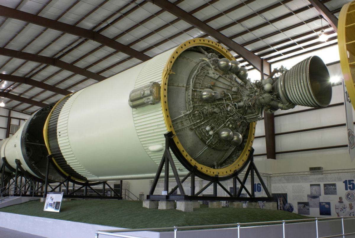
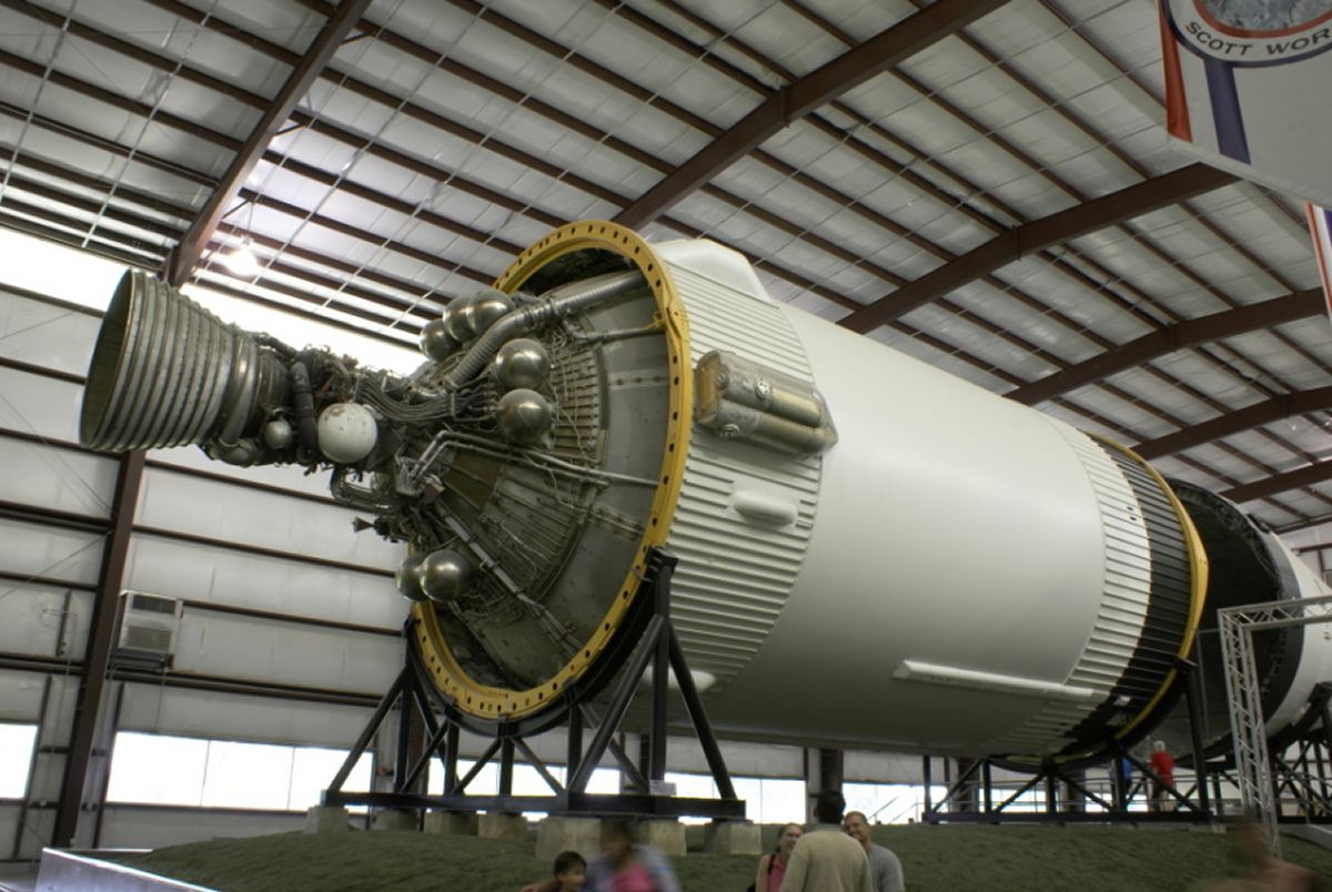
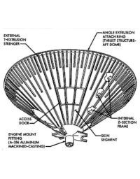
The thrust structure was an inverted, truncated cone attached at its large end to the LOX tank aft dome and attached at its small end to the engine mount. It provided the J-2 engine attach point and distributed engine thrust over the entire tank circumference. Engine piping, wiring, interface panels, eight ambient helium spheres, hydraulic system, oxygen/hydrogen burner, and some of the engine and LOX tank instrumentation was attached to the thrust structure exterior.
The cylindrical aft skirt was the load bearing structure between the propellant tank and aft interstage. The aft skirt was bolted to the tank at its forward edge and connected to the aft interstage via frangible tension ties that separated it from the aft interstage at S-II stage separation.
The aft interstage was a truncated cone that supported the load between the S-IVB stage and the S-Il stage. The interstage also provided the electrical and mechanical interface between the S-II and S-IVB stages. The S-II retrorocket motors were attached to this interstage, which at stage separation remained attached to the S-II stage.
S-IVB Structure
 |
 |
 |
 |
| Components |
Tank Assembly Detail |
Thrust Structure Detail |
Insulation Detail |
S-IVB Systems
Time Bases
Certain discrete events were particularly important to the Saturn V flight program, since they periodically reset the computer time base against which all sequential events were referenced. These significant time base events were:
- T and T1 Liftoff (LO)
- T2 S-IC center engine cutoff (CECO)
- T3 S-IC outboard engine cutoff (OECO)
- T4 S-II cutoff
- T5 S-IVB Cutoff (boost phase)
- T6 S-IVB restart
- T7 S-IVB cutoff (orbital phase)
Several of these time base events are referenced in the following S-IVB systems discussion.
Propulsion System
The S-IVB stage burned twice during its mission. The first burn, immediately after S-II/S-IVB separation, inserted the vehicle into low earth orbit. The second burn sent the Apollo spacecraft to the moon.
At T5, the APS ullage motors were ignited and burned for 1:28 minutes, providing stabilization and propellant settling. At APS engine ignition, the APS yaw and pitch control modes were enabled (roll was already active) for the required attitude control during coast. LH2 continuous propulsive venting was activated at T5 + 59.0 seconds and continued until the oxygen/hydrogen (O2/H2) burner second start.
Prior to second S-IVB burn systems were again readied for an engine start. Approximately 4 minutes before restart, the chilldown systems were reactivated to condition the lines by removing gases collected in the propellant supply system. The O2/H2 burner was started approximately 9 minutes prior to second burn to pressurize the propellant tanks ullage space and to provide thrust to settle the propellants.
LH2 continuous venting was terminated immediately after the O2/H2 burner start. Approximately one minute before engine start, the APS ullage engines were fired and the O2/H2 burner was shut down. The recirculation system was deactivated and engine restart was initiated. With this, the APS ullage engines were shut off, and the APS yaw and pitch control modes were deenergized. The roll control mode remained active throughout the second burn. At the end of the J-2 engine’s second burn the APS pitch and yaw modes were again enabled to provide attitude control during terminal coast. In addition, the LOX and LH2 tank pressures were vented through the stage nonpropulsive vents.
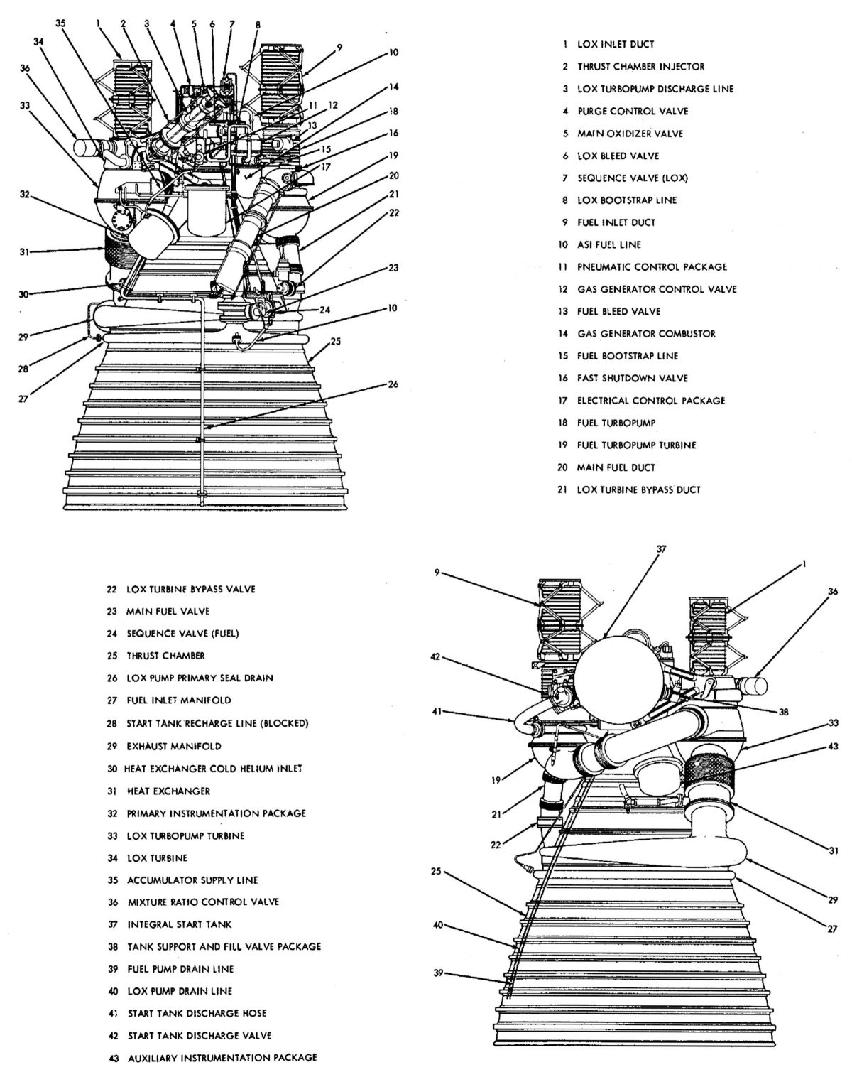
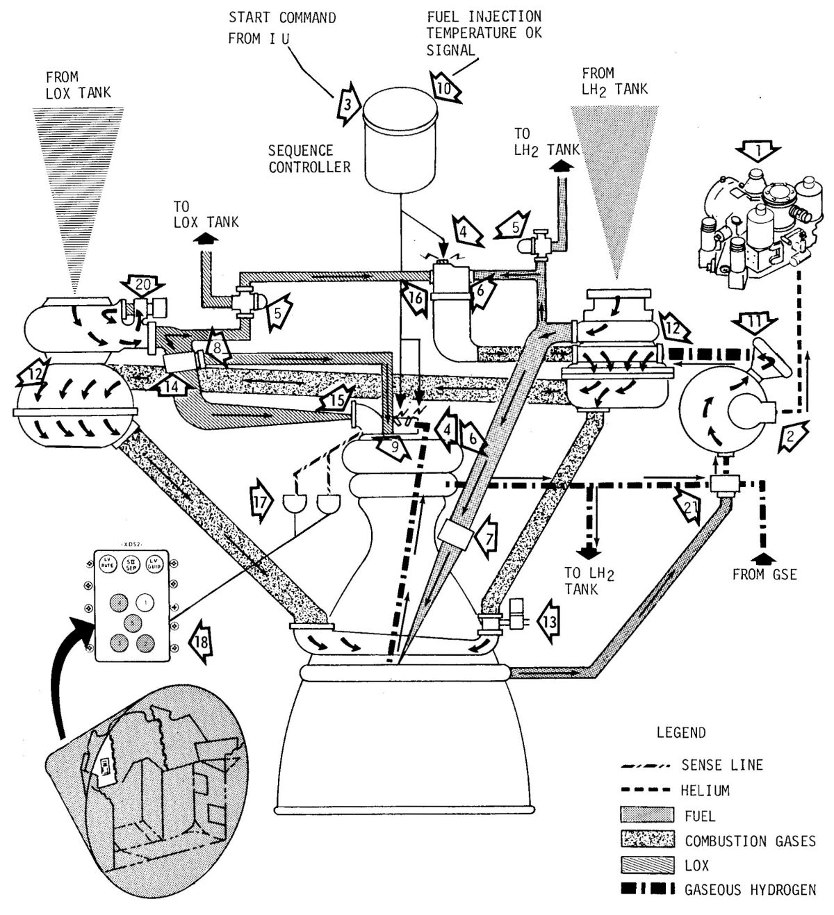
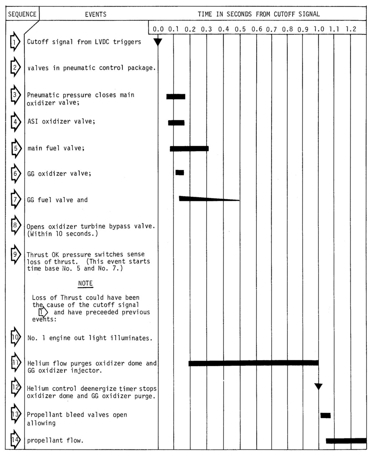
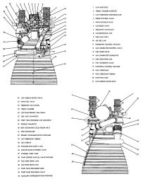
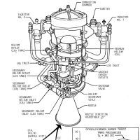
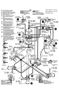
J-2 Rocket Engine
The J-2 featured an electrical control system that used solid state logic elements to sequence engine start and shutdown operations. Electrical power was supplied from the S-IVB aft battery No. 1. During the burn periods, the LOX tank was pressurized by expanding cold helium through the oxidizer turbine exhaust duct heat exchanger; he LH2 tank was pressurized by GH2 from the thrust chamber fuel manifold. Pitch and yaw plane thrust vector control was achieved by gimbaling the main engine. Hydraulic pressure for gimbal actuation was provided by the main hydraulic pump. During coast mode the APS engines affected pitch and yaw control. Roll control during both the burn periods and the coast modes was achieved by firing the APS engines.
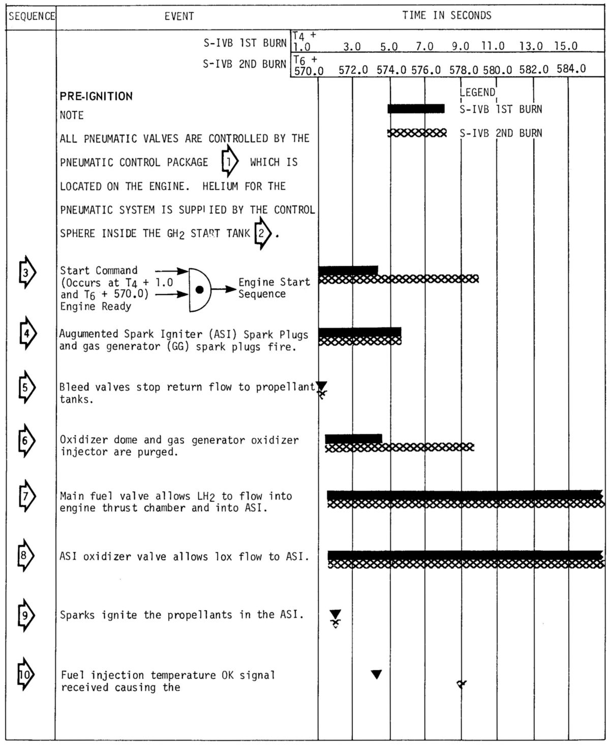
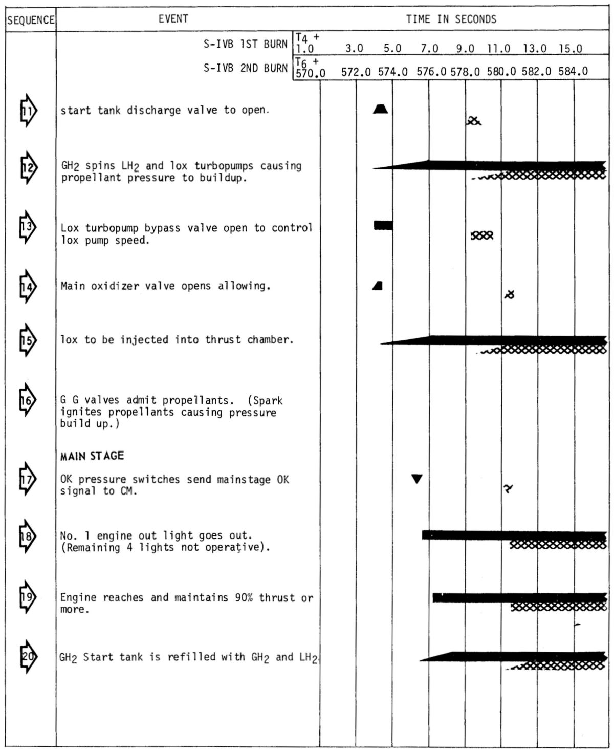
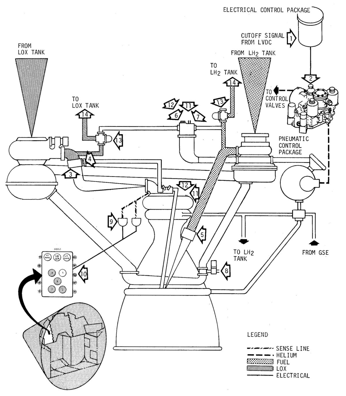
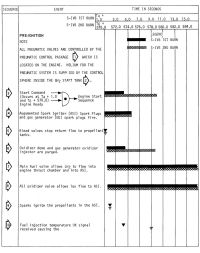
The J-2 received its start signals from the IU after which time the engine electrical control system sequenced and timed the start process. During mainstage, GH2 bled from the thrust chamber fuel injection manifold and LH2 bled from the ASI fuel line, refilled the start tank for engine restart. About 50 seconds of mainstage operation was required to recharge the start tank. Engine cutoff signals could be generated by EDS Nos. 1 or 2, range safety systems Nos. 1 or 2, thrust OK pressure switches, propellant depletion sensors, and an IU programmed command (velocity or timed) via the switch selector. The switch selector, range safety system No. 2, EDS No. 2, and the propellant depletion sensors cutoff commands were tied together (but diode isolated) and sent to the electrical control package cutoff circuit. The dropout of the thrust OK pressure switches removed a cutoff inhibit function in the electrical control package cutoff circuit. EDS No. 1 and range safety system No. 1 cutoff commands indirectly transferred the engine control power switch to the OFF position, causing the engine to shut down due to power loss. Each cutoff automatically reset the electrical control package circuitry, making it ready for restart if all reset conditions were met. The LVDC issued an engine ready bypass signal just prior to each engine start attempt; this bypass signal acted just as a cutoff would act.
J-2 restart was identical to the initial start except for the fill procedure of the start tank. Since the start tank was filled with both LH2 and GH2 during the previous burn period, a waiting period ranging from 90 minutes to 6 hours was required to ensure that sufficient energy was available for spinning the LH2 and LOX pump turbines. The wait time was required to build sufficient pressure by warming the start tank through natural means. The minimum wait was also needed to allow the hot gas turbine exhaust system to cool. Prolonged heating could eventually cause the start tank to lose pressure if the LH2 and GH2 warmed to the point the pressure relief valve popped off; if this venting continued for some time the total stored energy was depleted, which set the restart waiting period 6-hr upper limit.
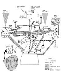
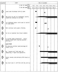
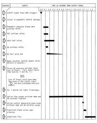
J-2 Engine Operation
 |
 |
 |
 |
 |
 |
| Nomenclature |
Startup Flow |
Startup Sequence 1 |
Startup Sequence 2 |
Cutoff Flow |
Cutoff Sequence |
Propellant Systems
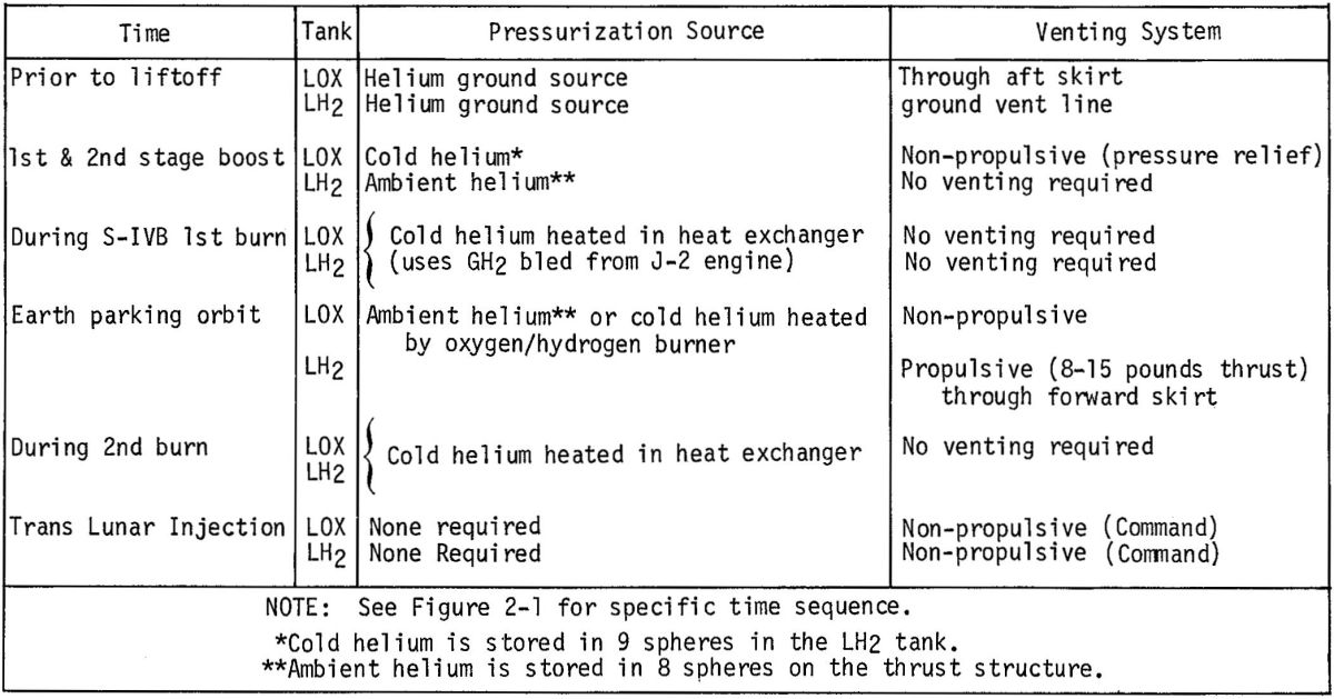
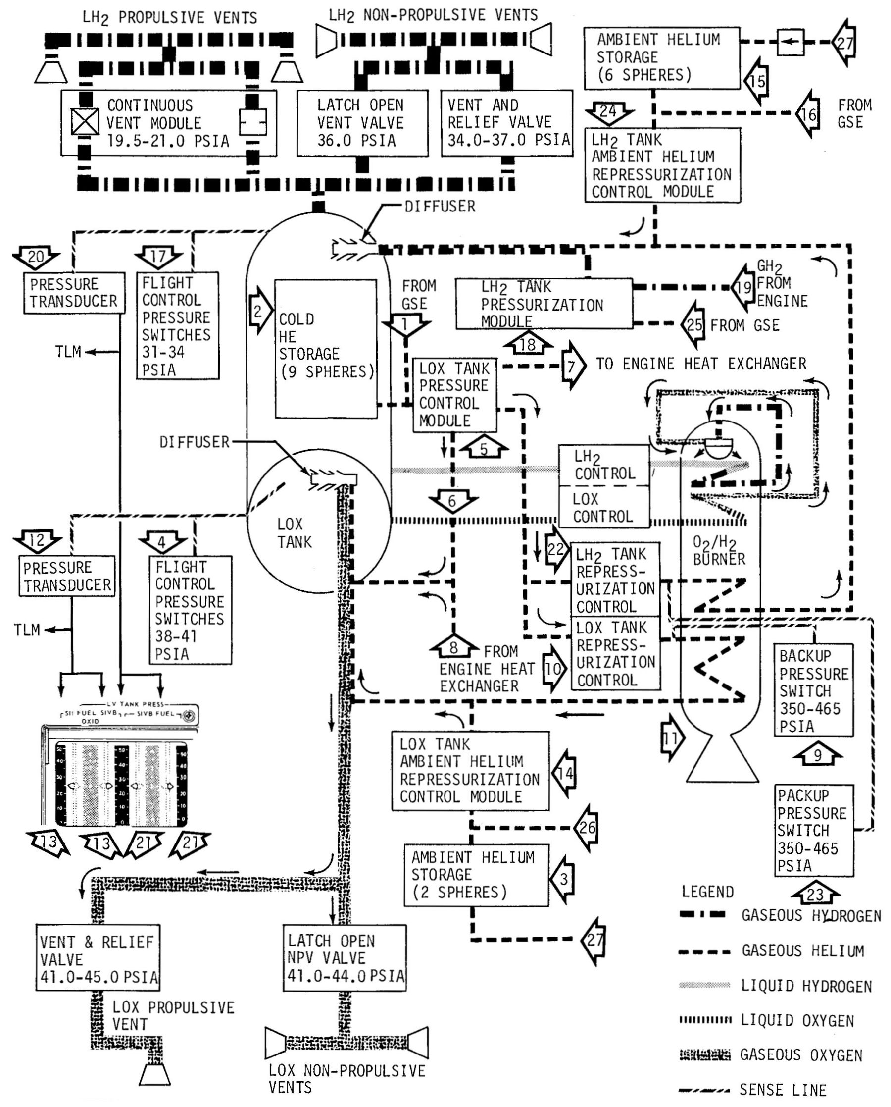
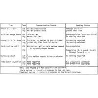
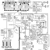
Each propellant tank was equipped with separate pressurization and repressurization systems to monitor and control tank pressures. This assured a minimum net positive suction head (NPSH) of 42 feet for LOX and 150 feet for LH2 at the turbopump inlets during engine start. Each tank was equipped with a pressure switch that opened or closed tank pressurization or repressurization control module valves. The control modules, in turn, metered pressurizing gases to the tanks as required. Prior to flight the ambient and cold helium storage bottles were filled, and the propellant tanks were pressurized from a cold helium GSE source.
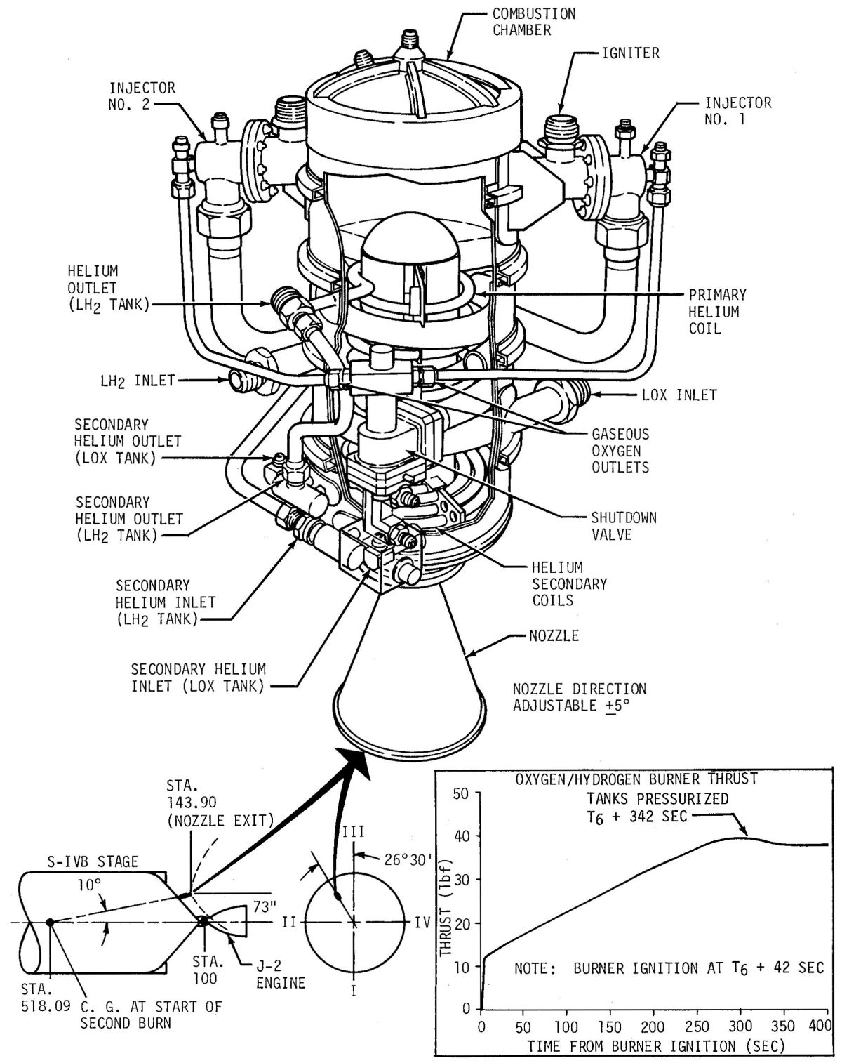
The O2/H2 burner heated helium to pressurize S-IVB propellant tanks during the earth parking orbit between the first and second J-2 burns. The O2/H2 burner propellants were ignited by spark plugs in the O2/H2 burner combustion chamber. Three sets of coils surrounded the chamber. One coil vaporized propellants for use in the O2/H2 burner; the other two coils produced warm GHe for LH2/LOX tank repressurization, a process controlled by the repressurization control module (dual valves). The O2/H2 burner produced 15 to 35 lbT through the S-IVB center of gravity.
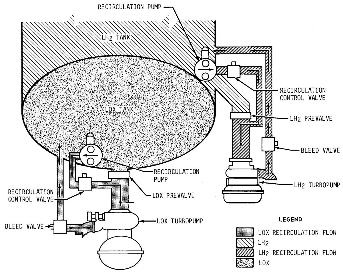
Propellant chilldown conditioned the ducting and engine to a low temperature, thereby eliminating bubbles (two-phase flow) prior to pressurization. The chilldown, along with the net positive suction head obtained by proper tank pressure levels, provided nominal starting conditions. During filling operations the prevalves stayed open to chill the feed system hardware (low pressure feed duct and engine pump), which stabilized the hardware prior to recirculation chilldown system activation. About five minutes before liftoff the prevalves were closed and recirculating chilldown flow was initiated. It continued for about 7.5 minutes, until J-2 engine prestart. Since LOX was already a subcooled liquid producing no two-phase flow (bubbles) in the return line, prepressurization had negligible effect on the flowrate. The LH2, however, became a subcooled liquid at prepressurization (eliminating return line two-phase flow), resulting in increased LH2 chilldown flow.
Chilldown conditioning of the engine pumps, inlet ducting and the engine hardware for both engine starts was accomplished by separate LOX and LH2 chilldown systems. Propellants from each tank were recirculated through the feed systems and return bleed lines by chilldown pumps. Check valves, prevalves, shutoff valves, and ducts control and route the fluids to perform the chilldown. Pneumatic pressure for operating the shutoff valves and prevalves was supplied by the stage pneumatic helium control bottle.
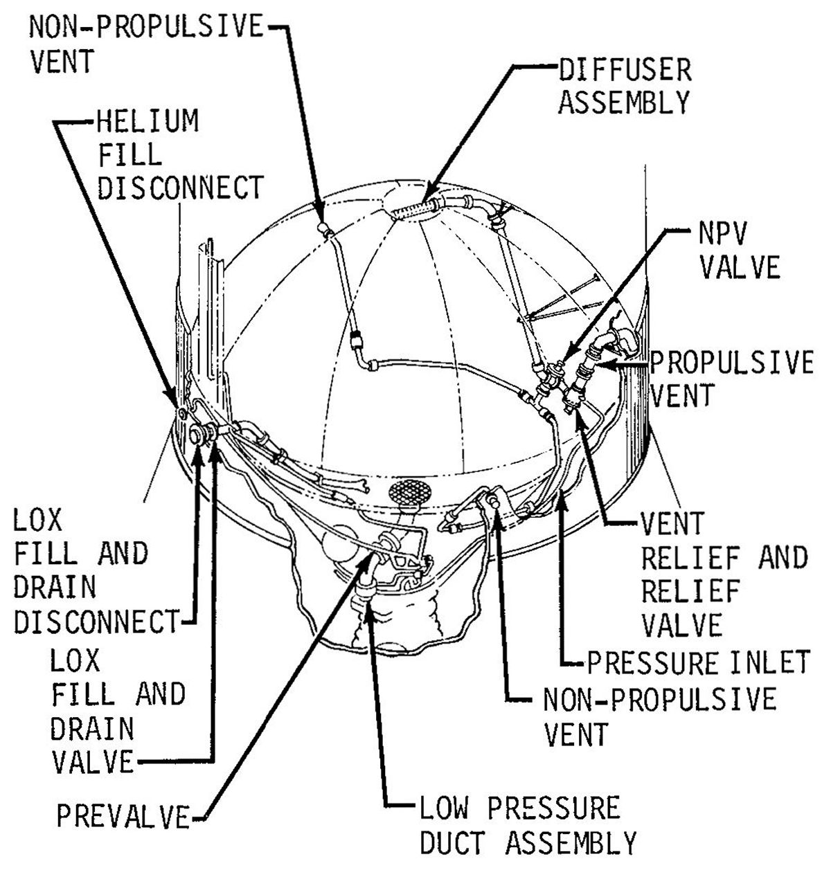
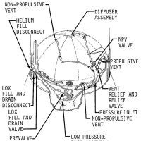
Propellant vent-relief subsystems protected the propellant tanks against overpressurization and enable command venting at any time that controlled venting of tank pressure was required. The LOX and LH2 tanks each had a command relief and venting subsystem. Both LOX and LH2 tank venting sequences provided for propulsive and non-propulsive venting. During loading, the LOX tank was vented through its propulsive vent duct, located in the aft skirt. During flight, LOX venting was normally a relief valve function and escaping vapors were routed through the non-propulsive vents. Either the flight program or ground commands could initiate non-propulsive venting. During fill, LH2 venting was routed through ground vent lines to the GH2 burn pond. At T-40 seconds, the vent valves were closed and the relief valves provided venting through the non-propulsive vents. Non-propulsive venting was continued until after the J-2 engine's first burn, when, as a part of second burn preparations, the LH2 tank was vented through the propulsive vents to provide propellant settling.
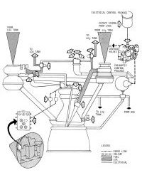
S-IVB Pressurization and Venting
 |
 |
 |
 |
 |
| Schedule |
O2/H2 Burner |
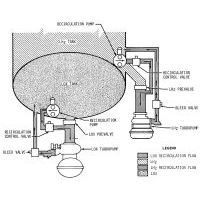
Recirculation Systems |
LOX Supply and Vent |
Schematic |
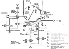
LOX System |
LOX Tank Pressurization and Vent |
LOX System
LOX was stored in the aft propellant tank at a temperature of -297° F. Total LOX tank volume was about 2,830 ft³, which included a 108 ft³ ullage volume. The tank was prepressurized by GHe at 38 - 41 psia and was maintained at that pressure during boost and engine operation. A LOX fill and drain valve allowed flow in either direction for fill or drain operations. During tank fill, the valve could flow 1,000 gpm at an inlet pressure of 51 psia. Pneumatic pressure for operating the fill and drain valve was supplied by the stage pneumatic control system. Loading began with a precooling flowrate of 500 gpm. When the 5% load level was reached, fast fill (1,000 gpm) was initiated. At the 98% load level, fast fill stopped and a slow fill at 300 gpm began. A fast fill emergency cutoff sensor backed up primary control cutoff failure. Slow fill was terminated at the 100% load level and this level was then maintained by a replenish flowrate of 0 to 30 gpm, as required. The replenish flow was maintained through the complete LOX tank prepressurization operation and the 100 % LOX load operation. LOX mass probes monitored liquid level during fill. Pressure sensing switches controlled tank pressure during fill and flight. In the event of LOX tank overpressurization (41 ± 0.5 psia) the LOX tank ground fill valve pressure switch signaled the ground automatic sequencer to close the LOX ground fill valve. A 6" low pressure supply duct supplied LOX from the tank to the engine. During engine burn, LOX flowed at a nominal 392 pounds per second at a pressure above 37 psia. The supply duct was equipped with bellows to provide compensating flexibility for engine gimbaling, manufacturing tolerances and thermal movement.
Three procedures comprised LOX tank pressurization: prepressurization, pressurization, and repressurization. Prepressurization involved that portion of the pressurization performed on the ground prior to liftoff. Pressurization refered to engine burn periods. Repressurization denoted pressurization just before a burn period. GSE-supplied cold helium was used during the prepressurization period to maintain tank pressure and to charge the nine cold helium storage spheres, which were located in the LH2 tank and supplied cold helium for both the pressurization and repressurization periods. The ambient helium storage spheres were filled by GSE and were an alternate source of repressurization helium. Irrespective of the pressurization procedure in use, LOX tank pressure was controlled by dual-redundant flight control pressure switches hooked to solenoid shutoff valves in each supply subsystem.
Prepressurization – At T-167 seconds, GSE pressurized the LOX tank. Pressure-regulated cold helium passed through the LOX tank pressure control module and flowed into the LOX tank until pressure increased to 41 psia, at which time prepressurization was completed and the flight control pressure switch shut off the cold helium supply.
Pressurization – After S-II/S-IVB separation at T4 + 0.8 sec, the LOX tank flight pressure system was activated, routing cold helium from cold helium storage spheres via the LOX tank pressure control module to the J-2 engine heat exchanger. Cold helium passing through the LOX tank pressure control module had its pressure reduced to about 385 psia. After expanding in the heat exchanger the LOX was routed to the LOX tank. A small portion of cold helium bypassed the heat exchanger through a control orifice, and mixed with the hot gas prior to entering the LOX tank. The flight control pressure switch controlled a solenoid valve in the LOX tank pressure control module to regulate LOX tank pressure to 38 - 41 psia. Helium flow to the LOX tank was monitored by a backup pressure switch that regulated pressure by operating LOX tank pressure control module solenoid valves if normal pressure regulation failed. An S-IVB LOX tank pressure reading became available in the command module (CM) at S-II/S-IVB separation. This pressure was sensed by the pressure transducer and was relayed to the S-II FUEL/S-IVB OXID gauges in the CM and, via telemetry, to the ground.
Repressurization – The normal repressurization procedure was initiated at T6 + 48.1 seconds. Cold helium from the cold helium spheres underwent a pressure reduction to about 385 psia as it flowed through the LOX tank pressure control module. It next flowed through the LOX tank repressurization control, and into the O2/H2 burner. If the LOX tank pressure control module failed, the backup pressure switch maintained a pressure of 350-465 psia at the O2/H2 burner. The backup pressure switch controled the pressure by opening or closing valves in the LOX tank repressurization module. As the cold helium was heated in the O2/H2 burner it expanded and was routed to the LOX tank. LOX tank pressure increase was sensed by the flight control pressure switch and pressure transducer . The pressure switch maintained LOX tank pressure between 38-41 psia by opening and closing solenoid shutoff valves in the LOX tank repressurization control module. The pressure transducer transmitted a continuous pressure reading to telemetry and to the LV TANK PRESS gauges in the CM. At T6 + 496.6 seconds, cryogenic repressurization was switched off. Ambient repressurization was turned on at T6 + 497.6 seconds. Ambient helium from the ambient helium storage spheres flowed via the LOX tank ambient helium repressurization control module to the LOX tank where its pressure was sensed by the flight control pressure switches, which regulated LOX tank pressure by opening or closing control valves in the LOX tank ambient helium repressurization control module. Just before the J-2's second burn, ambient repressurization was terminated (T6 + 520.0 seconds).
LOX Venting – The LOX tank vent subsystem controlled LOX tank venting during normal stage operation and pressure relief venting when tank overpressures occurred. The LOX tank venting subsystem operated through a ground controlled combination vent and relief valve. This valve was pneumatically operated upon receipt of the ground command. Prior to loading, the vent and relief valve was placed in the open position and LOX boil-off during loading was directed through one propulsive vent in the stage aft skirt. When LOX tank prepressurization commenced, the valve was closed and placed in the relief position. Over-pressures from the LOX tank were then be vented as necessary. A ground commanded non-propulsive LOX tank vent function was available via two non-propulsive vents placed 180° apart.
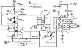
LH2 Tank Pressurization and Vent |
LH2 System
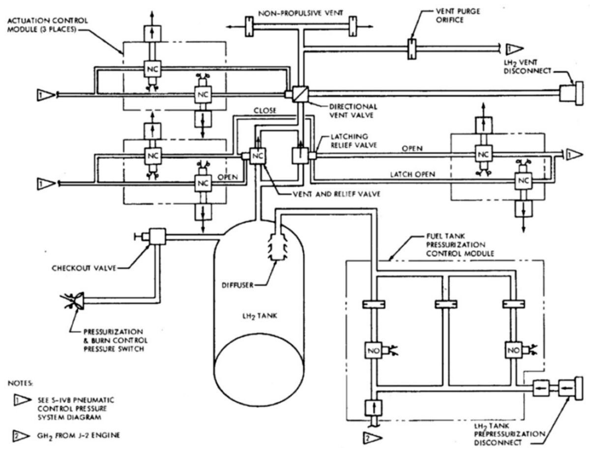
LH2 was stored in an insulated tank at -423°F. Total tank volume was about 10,500 ft³ with an ullage volume of about 300 ft³. The LH2 tank was prepressurized at 28 - 31 psia. A vacuum-jacketed 10" low pressure LH2 duct connected the LH2 tank to the J-2 fuel turbopump. This duct could flow 80 pounds per second at 28 psia. The duct origin was in the aft tank side wall above the common bulkhead joint. Bellows in this duct compensated for engine gimbaling, manufacturing tolerances, and thermal motion. Prior to loading, the LH2 tank was purged with helium gas to remove any air that would have been liquefied when the super-cooled LH2 began flowing. When loading began the ground-controlled combination vent and relief valve was opened, and the directional control valve was positioned to route GH2 overboard to the burn pond. Loading started with a precool flow rate of 500 gpm. When the 5% load level was reached, fast fill was initiated at a flow of 3,000 gpm. At the 98% load level, fast fill stopped and a slow fill at 500 gpm began. A fast fill emergency cutoff sensor compensated for a primary control cutoff failure. Slow fill was terminated at the 100% load level, and this level was then maintained by a replenish flowrate of 0 to 300 gpm, as required. The replenish flow was maintained through the LH2 tank prepressurization operation. Liquid level during fill was monitored by means of the LH2 mass probes. A backup overfill sensor was provided to terminate flow in the event of a 100% load cutoff failure. A LH2 vent system provided command venting of the LH2 tank plus overpressure relief. Pressure sensing switches controlled tank pressure during fill and flight.
LH2 Tank Pressurization – Three procedures comprised LH2 tank pressurization: prepressurization, pressurization, and repressurization. Prepressurization was used on the ground prior to liftoff; pressurization was used during engine burn periods, and repressurization was used just before the second burn period. GH2 and GHe were used as the pressurants. GSE-supplied cold helium was used during the prepressurization period. Cold helium storage spheres located inside the LH2 tank supplied cold helium for repressurization. Five ambient helium storage spheres, located on the thrust structure and filled by GSE, supplied an alternate source of helium for use during the repressurization period. LH2 tank pressure was controlled by dual redundant flight control pressure switches regardless of the pressurization procedure. These switches controlled solenoid shutoff valves in each of the supply subsystems.
Prepressurization – LH2 tank prepressurization, controlled by GSE, commenced at T1 - 97 seconds. Cold helium flowed through the LH2 tank pressurization module and into the LH2 tank. When the LH2 tank pressure increased to 31 psia (T1 - 43 seconds), the flight control pressure switch shut off the ground supply of cold helium to complete prepressurization.
Pressurization was controlled by the flight control pressure switches, which opened or closed solenoid valves in the LH2 tank pressurization module. GH2 bled from the J-2 engine flowed through the LH2 tank pressurization module to the LH2 tank. As pressure in the LH2 tank increased to 31 psia, the flight control pressure switches close valves in the LH2 tank pressurization module to maintain tank pressure at 28-31 psia. This pressure was sensed by a pressure transducer and was relayed to the S-IVB fuel gauges in the CM and, via telemetry, to the ground. In this manner, LH2 tank pressurization was maintained during engine burn periods.
Normal repressurization began at T6 + 48.1 seconds using cold helium from the cold helium storage spheres. Cold helium pressure was reduced to about 385 psia as it flowed through the LOX tank pressure control module. The cold helium next flowed through the LH2 tank repressurization control, and into the O2/H2 burner. If the LOX tank pressure control module regulator failed, the backup pressure switch maintained a pressure of 350 - 465 psia at the O2/H2 burner. The backup pressure switch opened or closed valves in the LH2 tank repressurization module. As the cold helium was heated in the O2/H2 burner, it expanded and was routed to the LH2 tank. Increasing LH2 tank pressure was sensed by the flight control pressure switch and the pressure transducer. The pressure switch maintains LH2 a 28 -31 psia tank pressure by opening and closing solenoid shutoff valves in the LH2 tank repressurization control module. The pressure transducer transmitted a continuous pressure reading to telemetry and to the LV TANK PRESS gauges in the CM. At T6 + 496.6 seconds, cryogenic repressurization was switched off. Ambient repressurization was turned on at T6 + 497.6 seconds. Ambient helium from the ambient helium storage spheres flowed through the LH2 tank ambient helium repressurization control module to the LH2 tank. Here the pressure was sensed by the flight control pressure switches, which controlled LH2 tank pressure by opening or closing LH2 tank ambient helium repressurization control module control valves. Just before the J-2's second burn, ambient repressurization was terminated (nominally at T6 + 520.0 seconds).
LH2 Venting – The LH2 tank vent subsystem could perform either a propulsive or non-propulsive (normal) venting. Non-propulsive venting made use of a ground controlled combination vent and relief valve that routed GH2 through either the ground vent lines or non-propulsive relief venting. The valve was in the ground-vent-line-open position until T-40 seconds at which time it was positioned to the in-flight non-propulsive relief function. Non-propulsive vents were located 180° to each, canceling any thrust effect. Propulsive venting operated through two control valves upstream of the non-propulsive control valve. This mode vented the GH2 through two propulsive vents located axial to the stage. Propulsive venting provided a small additional thrust, prior to the second J-2 burn, for propellant settling
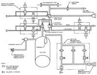
Pneumatic Control |
Pneumatic Control
The pneumatic control system, which provided pressure for all pneumatically operated stage valves and for the J-2 start tank vent valve, was filled with GHe from GSE to 3,200 ± 100 psig. The onboard pneumatic control system consisted of the helium fill module, an ambient helium bottle and a pneumatic power control module.
The helium fill module regulated the incoming supply to 490 ± 25 psia for operation of control valves during preflight activities. The ambient helium storage bottle was initially pressurized to 750 psia, and was capable of supplying operating pressure to stage control valves at that pressure. After propellant loading began and the cold helium bottles were chilled down the pressure was raised to 3,100 psia; both the ambient and cold helium bottles were then completely pressurized to their flight pressure of 3,100 psia by the time the LH2 tank reached a 92% load level.
The pneumatic power control module was set at 475 psig, which was equivalent to 490 psia on the ground and 475 psia in orbit. These pressure levels were essential to the operation of the LH2 directional control valve, the propulsion vent shutoff valve, the LOX and LH2 fill and drain valves, the LOX and LH2 turbopump turbine purge module, the LOX chilldown pump purge control, the LOX and LH2 prevalves and chilldown and shutoff valves, the LOX tank vent/relief valves, the LH2 propulsive vent valve, and the J-2 GH2 start system vent/relief valve. Each pneumatically operated component was attached to a separate actuation control module containing dual solenoids, which provided on-off control. The pneumatic control system was protected from over-pressure by a normally-open pressure-switch-controlled solenoid valve. This switch maintained system pressure between 490 - 600 psia.
Thrust Vectoring |

Hydraulic System |
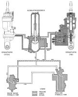
Flight Control
The flight control system used J-2 engine gimbaling for pitch and yaw thrust vector control during powered flight; the APS engines furnished roll control. APS engines operating alone provided attitude control during coast flight. During the S-IC and S-II boost and S-II/S-IVB separation phase, the J-2 was commanded to the null (zero gimbal angle) position to prevent damage by shifting. This minimized the possibility of contact between the engine bell and the interstage at S-II/S-IVB separation, and minimized inertial effects at ignition. The engine was gimbaled in a 7.0° square pattern by a closed loop hydraulic system. Mechanical feedback from the actuator to the servovalve completed the closed engine position loop. When a steering command was received from the IU flight control computer (FCC), a torque motor in the servovalve shifted a control flapper to direct the fluid flow through one of two nozzles based upon signal polarity. Two actuators translated the steering signals into vector forces to position the engine. The deflection rates were proportional to the pitch and yaw steering signals from the FCC.
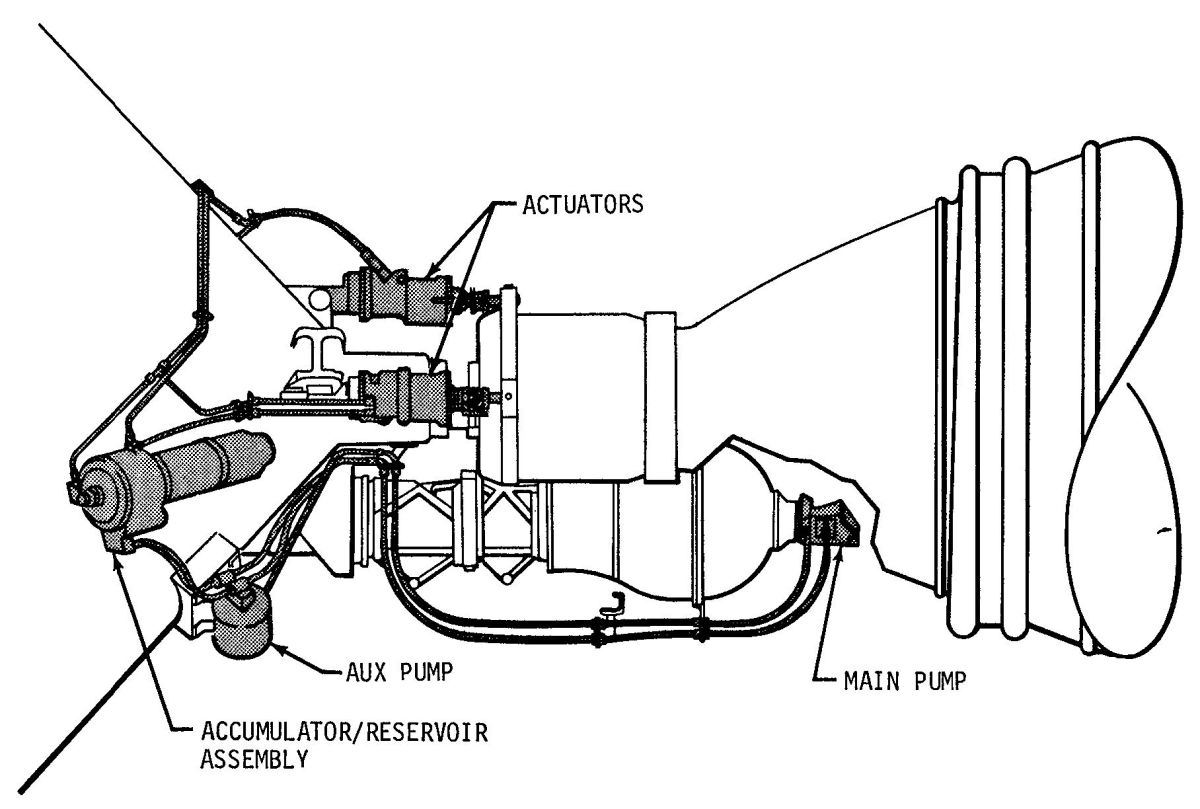
Hydraulic System – An engine-driven hydraulic pump, an electrically-driven auxiliary hydraulic pump, two hydraulic actuator assemblies, and an accumulator/reservoir assembly comprised the hydraulic system. The variable-displacement engine-driven hydraulic pump was driven directly from the engine oxidizer turbopump and delivered up to 8 gpm under continuous working pressure. The electrically-driven auxiliary hydraulic pump was capable of supplying a minimum of 1.5 gpm for preflight checkout, to lock the J-2 engine in the null position during boost and separation, and as emergency backup. During orbit, the auxiliary pump, controlled by a thermal switch, circulated the hydraulic fluid to maintain its temperature between +10°F and +40°F. The auxiliary pump was enabled before liftoff and during coast periods. The accumulator/reservoir assembly, mounted on the thrust structure, stored 167 in³ of hydraulic fluid at 60 - 170 psig. Two pressure-operated pistons within the accumulator section maintained this reservoir pressure, supplemented peak system demands and dampened high pressure surging. The pitch and yaw actuators/servovalves were interchangeable, linear, double-acting devices that provided pitch and roll control proportional to pitch and yaw steering signals from the FCC.
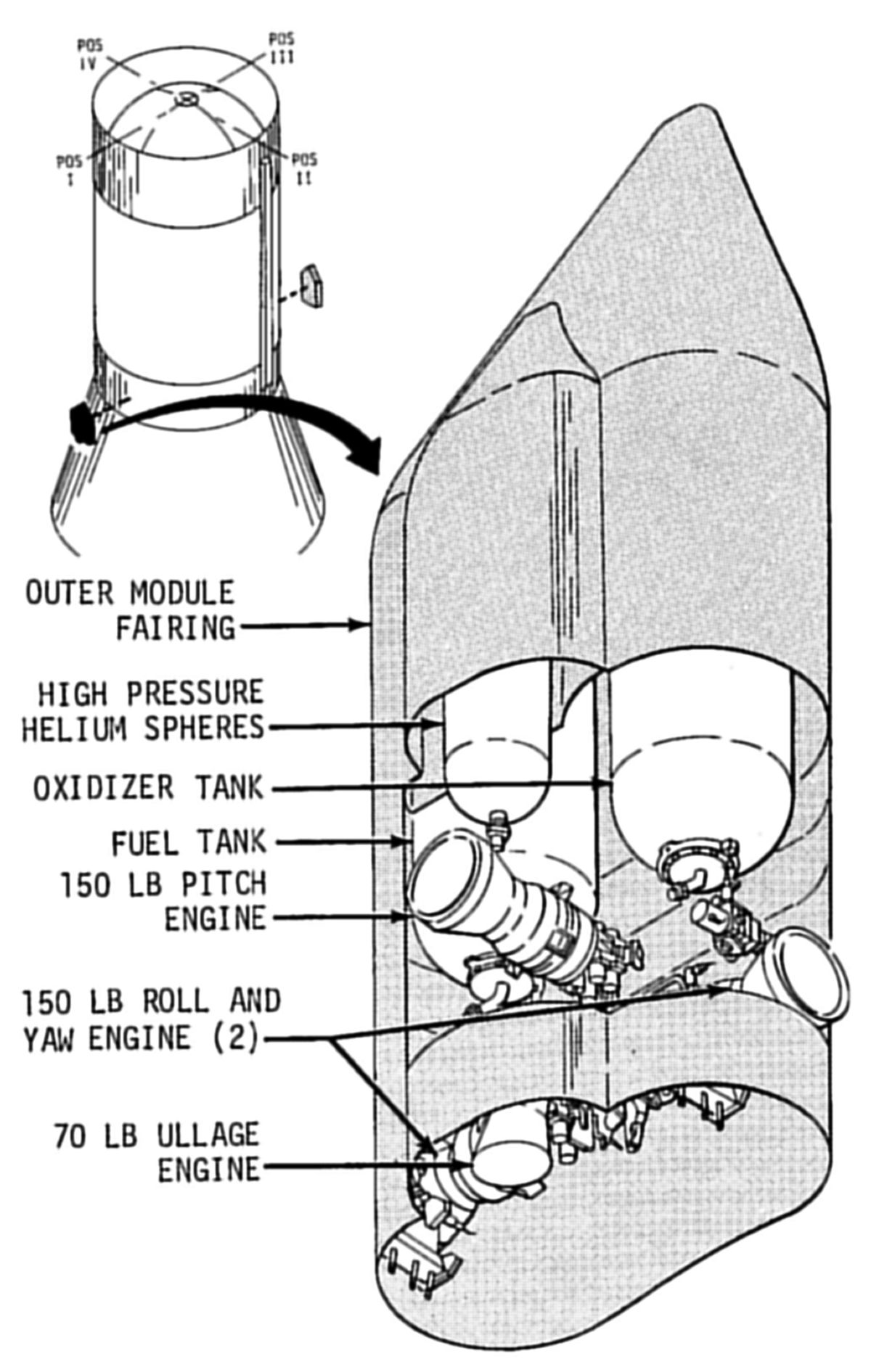
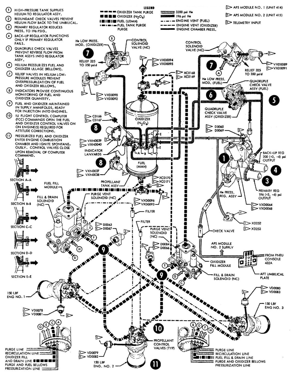
Auxiliary Propulsion System
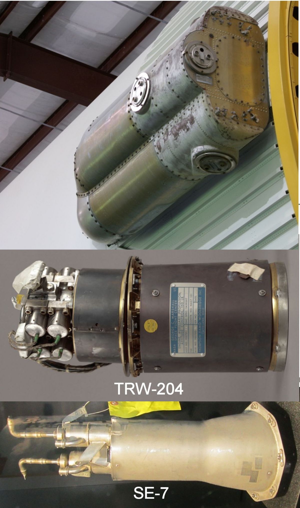
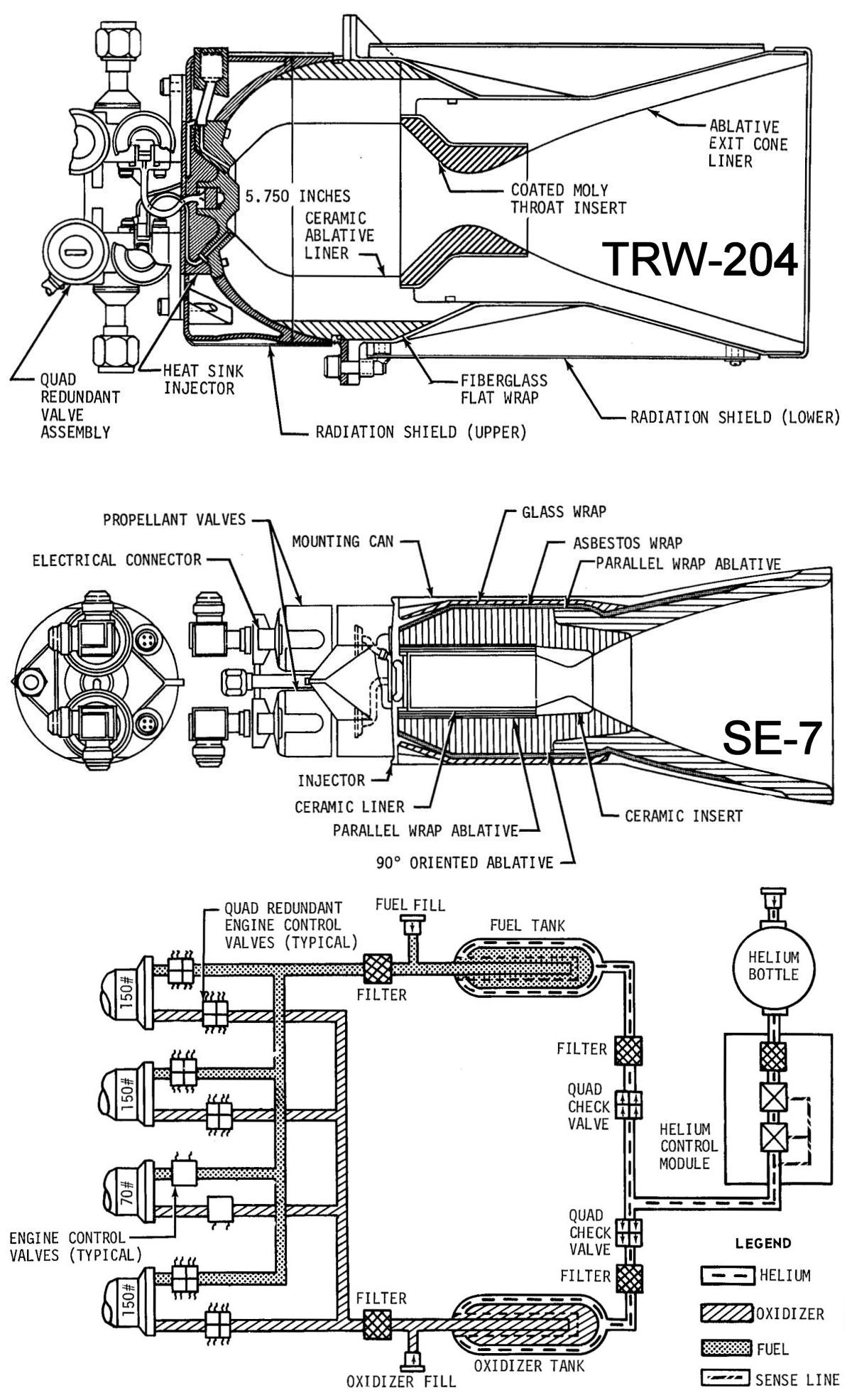
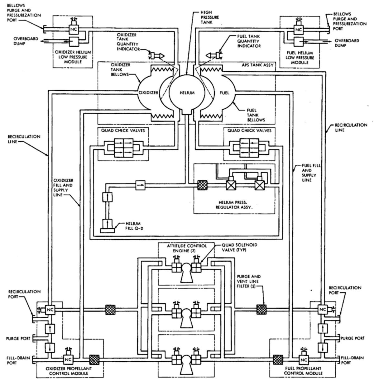
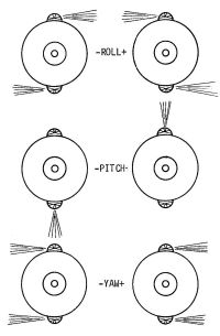
The S-IVB auxiliary propulsion system provided roll control during J-2 burns and three axis attitude and propellant control during coast flight. APS engines were located in two detachable modules spaced 180° apart on the S-IVB aft skirt. Each module contained four engines: three TRW TR-204 150-lbT attitude control engines and one Rocketdyne SE-7-1 70-lbT ullage engine. Each module contained its own oxidizer, fuel, and pressurization systems. A positive expulsion propellant feed subsystem was used to ensure that hypergolic propellants were supplied to the APS engines under zero or random gravity conditions. This consisted of separate fuel and oxidizer propellant tank assemblies, each containing a bladder for propellant expulsion, individual propellant control modules that filtered the propellants and provided auxiliary ports for subsystem servicing operations, and a propellant manifold for propellant distribution to the engines. MIL-P-27404 monomethyl hydrazine (MMH) was used as fuel and MIL-P-28539A dinitrogen tetroxide (N204) was used as an oxidizer for APS engines. The 150-pound thrust engines utilized eight control valves (four for fuel, four for oxidizer) in a fail safe series-parallel arrangement. The 70-pound ullage engine used only single valves on both the fuel and oxidizer lines.
Two of the three 150-pound thrust engines in each module control roll and yaw, while one controlled pitch. The 70-pound thrust engine settled propellants just prior to J-2 engine restart. The minimum engine firing pulse duration was about 70 ms. A signal from the IU energized the pitch control relays, which opened the eight normally-closed quad redundant propellant valves (4 oxidizer, 4 fuel) arranged in two series-parallel circuits. Valve assembly failure occurred only if two valves failed open in series (propellant drain), or two valves fail closed in parallel (oxidizer or fuel starvation). Single valve failures did not affect engine efficiency or performance. The attitude deviation dead band for roll, pitch, and yaw was ± 1°.
The APS attitude engine control signal was composed of an attitude error signal and a vehicle turning rate signal. The Control/EDS rate gyros, located in the IU, supplied vehicle turning rate information. Attitude error information come from either the IU FCC of the spacecraft. Attitude error signals from the spacecraft originated in the Apollo navigation, guidance and control system or by an astronaut through manual control. The LVDC imposed limits on IU-generated attitude error signals, and the IU FCC similarly limited spacecraft-generated attitude error signals. These attitude error limits, ± 2.5° for pitch and yaw, and ± 3.5° for roll, prevented excessive propellant usage that would have resulted from large angular rate commands. These error signals were used only by the APS.
The Apollo spacecraft attitude reference system could follow the instantaneous vehicle attitude by driving the command display unit servomotor with an error signal formed by differencing the commanded and actual gimbal angles. When the astronaut wished to maintain a particular attitude, he used the computer to set the command display unit command resolver to the desired gimbal value. The difference between the commanded and actual gimbal angles resulted in an error signal that was resolved into vehicle coordinates and was given to the IU FCC as an attitude error signal. The S-IVB attitude control system then operated in the limit cycle mode about this command attitude.
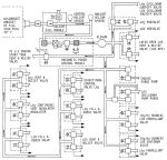
S-IVB Auxiliary Propulsion System
 |
 |
 |
 |
 |
 |
| Components |
Functionality |
APS, Engines
(heriocrelics.org) |
Sections and
Simplified Schematic |
Detailed Schematic |
Operation |
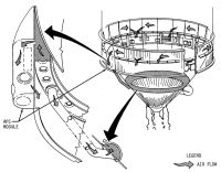
Aft Skirt Environmental Control |
Thermal Conditioning
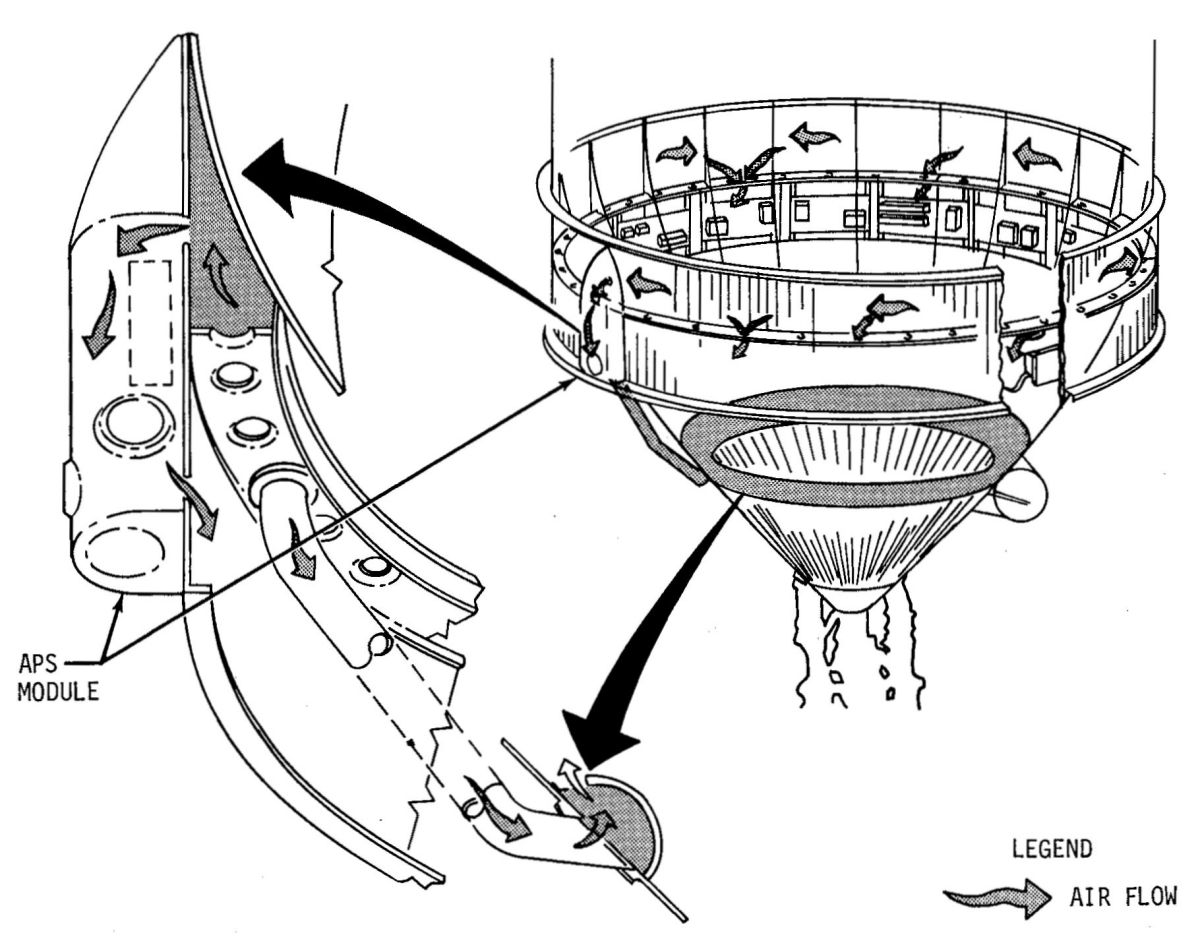
During checkout and pre-launch operations the electrical equipment, APS and hydraulic accumulator reservoir environments were cooled or heated by GSE. In addition, there was forward skirt, aft skirt and interstage purging.
During countdown, air or GN2 was supplied at about 3,600 scfm by the environmental control system, which was capable of switching from air to GN2 purge. The air purge was initiated when electrical power was applied to the vehicle. GN2 flow was initiated 20 minutes prior to LOX chilldown (at T-8 hrs.) and continued until liftoff. During periods of hold, GN2 purge was continued. The aft skirt and interstage thermal conditioning and purge subsystem maintained nominal electrical equipment, APS, hydraulic accumulator reservoir, and ambient helium bottle temperature in the aft skirt during ground operations. It also purged the aft skirt, aft interstage and thrust structure, and S-II stage forward skirt of oxygen, moisture and combustible gases.
The thermal conditioning subsystem consisted of a temperature-controlled air or GN2 distribution system. The purging gas passed over electrical equipment below the ring frame and flowed into the interstage. A duct from the skirt manifold directed air or GN2 to a thrust structure manifold. Another duct directed the gas to a shroud covering the ambient helium bottle used to purge LOX and LH2 pump shaft seal cavities. From the thrust structure manifold supply duct a portion of air or GN2 was directed to a shroud covering the hydraulic accumulator reservoir.
Equipment in the S-IVB forward skirt was thermally conditioned by heat transfer to a circulating coolant. The forward skirt thermal conditioning subsystem consisted of a fluid distribution subsystem and cold plates. Coolant was supplied to the S-IVB by the IU thermal conditioning system starting when electrical power was applied to the vehicle and continuing throughout the mission. The forward skirt area was purged with GN2 to minimize the danger of fire and explosion while propellants were being loaded or stored in the stage, or during other hazardous conditions. The purge was supplied by the IU purge system with a flow rate of about 3,500 scfm.

Electrical System |
PU System |
Electrical
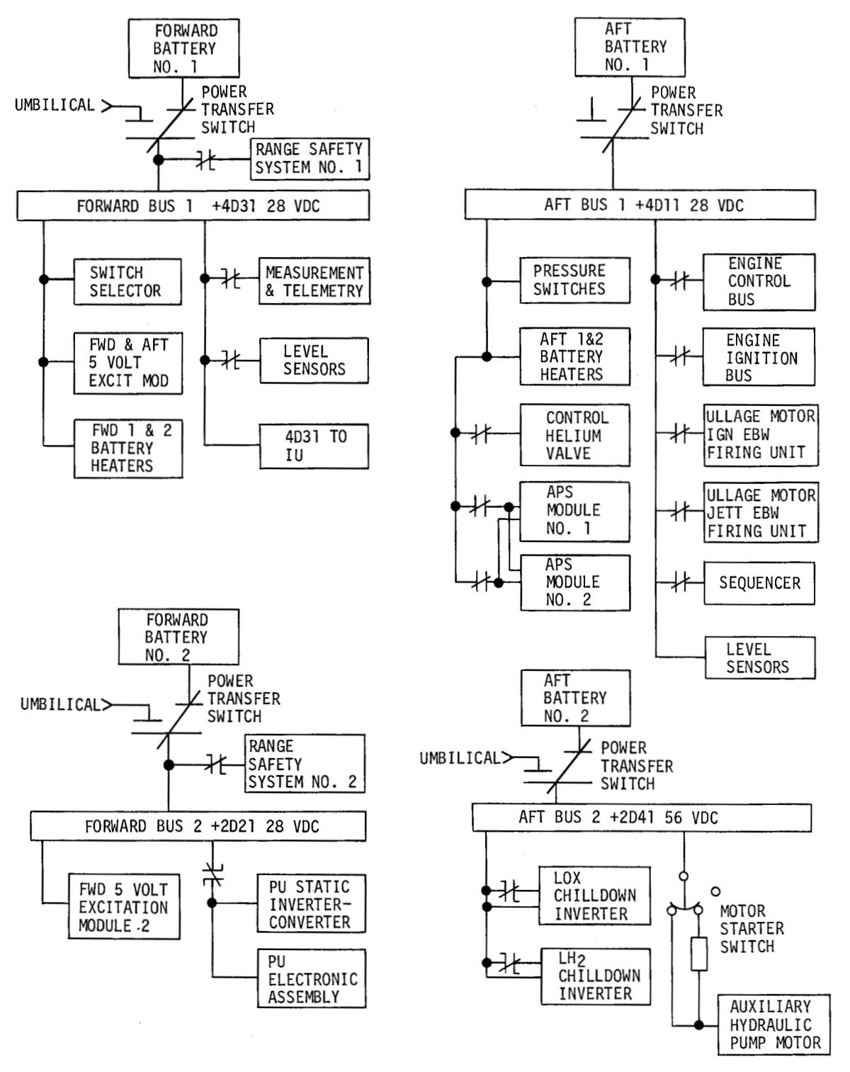
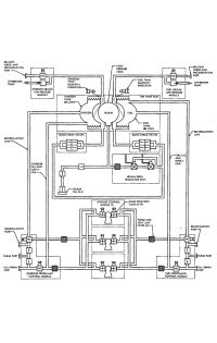
The S-IVB stage electrical system was composed of the electrical power subsystem, which included all power sources, and the electrical control subsystem, which distributed power and control signals to various loads. On board power came from four zinc/silver-oxide batteries, two in the forward equipment area and two in the aft equipment area. These batteries were activated and installed during final prelaunch preparations. Heaters and instrumentation probes were an integral part of each battery.
Power Distribution – Two main forward busses and two main aft busses supplied electrical power to all stage systems. Busses were electrically isolated from each other and each main bus used a power transfer switch to switch from GSE power to stage batteries.
- Forward bus No. 1 provided 28 VDC power to the telemetry transmitters, data acquisition system, transducers, level sensors, switch selector, range safety system No. 1, checkout measurement group, 5 VDC excitation modules and the forward battery No. 1 and No. 2 heaters.
- Forward bus No. 2 supplied 28 VDC power to the propellant utilization electronic assembly, the PU static inverter-converter, and range safety system No. 2. Redundant range safety and emergency detection system requirements dictated the use of a second battery in the forward skirt.
- Aft bus No. 1 supplied 28 VDC power to the J-2 engine, sequencer, pressure switches, all propulsion system valves which were flight operational, attitude control system modules No. 1 and No. 2, ullage motor ignition and jettison system, aft battery No. 1 and No. 2 heaters.
- Aft bus No. 2 provided 56 VDC power to the LH2 and LOX chilldown inverters and the auxiliary hydraulic pump motor. The 56-volt battery was necessary to meet thehigh power requirements of these loads.
- The chilldown inverters were three-phase, 1,500 volt-amp, solid state power conversion devices that provide electrical power to the motor driven pumps for LOX and LH2 circulation, ensuring propellant temperature stabilization at the J-2 engine inlets.
The PU static inverter-converter was a solid state power supply that provided regulated ac and dc voltages to operate the PU electronics assembly. It converted 28 VDC to the following outputs:
- 115 VAC 400 Hz for propellant utilization valve positioning motors and bridge rebalancing servomotors
- 2-VAC peak-to-peak square wave used to convert the propellant utilization error signal to alternating current
- 5 VDC for propellant utilization fine and coarse mass potentiometer excitation
- Regulated 22 VDC for propellant utilization bridges
- 117.5 VDC floating supply for propellant utilization summing potentiometer excitation
- 49 VDC floating supply for valve feedback potentiometer excitation
The 5-volt and 20-volt excitation modules were transistorized power conversion devices that converted 28-vdc to the various regulated voltages required by the instrumentation, signal conditioning, and emergency detection system transducers.
The electrical control subsystem distributed the command signals that controlled the stage electrical components. It consisted of power and control distributors, sequencer assemblies, pressure sensing devices and pressure control devices.
The stage sequencing system included the switch selector and the stage sequencer. Digital sequencing commands from the IU were interpreted by the switch selector, an electronic assembly that controlled stage inflight sequencing. The switch selector consisted of relays, a diode matrix, and low-power transistor switches that drove relays, which operated magnetically latching relays in the sequencer and power distribution assemblies. The switch selector electrically isolated the IU and the S-IVB stage, and provided up to 112 discrete commands to the stage sequencer.
The stage sequencer received discrete inputs from the switch selector (and other S-IVB stage subsystems) and managed S-IVB flight functions by supplying or removing power from the appropriate equipment. Sequence circuits performed logistical input gating necessary for sequencing with as few IU timed commands as possible.
Calibratable pressure switches (calips) performed various control functions, such as:
- LH2 tank pressurization, ground fill, valve control, and pressure control backup
- LOX tank pressurization, ground fill, valve control, and pressure control backup
- Pneumatic power system regulator backup, engine purge and LOX chilldown pump container purge
Calips were located in either the thrust structure or interstage, depending on the pressure control system in which the switch was used. Calips employed two pressure ports that were isolated from one another. The test port facilitated remote checkout without disconnecting or contaminating the primary pressure system. Test pressure settings were calibrated during switch manufacture. Calips used a single Belleville spring that provided "snap" response to actuation or deactuation pressures, thereby switching 28 VDC power relays in the stage sequencer for propulsion system solenoid valve control.
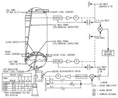
Propellant Management
The propellant management system monitored and controlled propellants during all stage operation phases. Continuous capacitance probes and point level sensors in both the LH2 and LOX tanks monitored propellant mass. GSE used point level sensors during propellant loading to gauge propellants levels. Level sensors signalled the LVDC during flight so that engine cutoff at propellant depletion was smooth. Capacitance probes were used to operate the J-2's PU control valve, a rotary valve that controlled LOX flow. The PU valve followed a signal developed from propellant monitoring capacitance probes so that propellant residuals at flight termination were minimal. Prior to S-IVB first-burn ignition the PU valve was commanded to its null position. This resulted in a MR of about 5:1 for start and throughout the first burn. Prior to S-IVB restart the PU valve was commanded to its full-open position. This produced a MR of approximately 4.5:1 during the start sequence. After about 2.5 seconds the PU valve returned to its null position for a MR of approximately 5:1 for the remainder of the second burn.
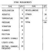
Instrumentation
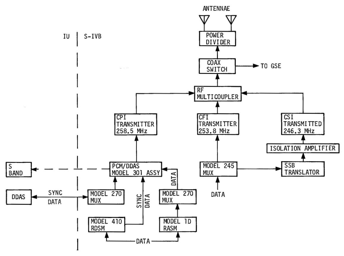
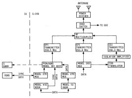
S-IVB instrumentation monitored stage systems operation. Before liftoff, measurements were telemetered by coaxial cable to GSE; during flight, radio frequency antennae conveyed data to ground stations. The measurement subsystem acquired stage functional data from several transducer types, conditioned it, and supplied it to the telemetry system for transmission to the ground stations.
Platinum wire temperature transducers, whose resistance changed with temperature and thermocouples that produced a voltage proportional to temperature measured temperature. Individual bridges and DC voltage amplifiers conditioned each temperature measurement. In cases where the temperature bridge connected directly to the remote analog submultiplexer (RASM), the external DC voltage amplifier was omitted. Potentiometer (5,000 ohm) type and strain gauge type pressure transducers monitored pressure. Potentiometer type transducers were used on 12 sample-per-second measurements where transducer temperature was no colder than -100°F. Strain gauge transducers were used on all 120 sample-per-second measurements, and where transducer temperature was colder than -100°F. All strain gauge transducers had a high and low simulation calibration capability. Conventional turbine type flowmeters with frequency to direct current (0 - 5 DC) measured flow. Actuator and metering valve positions were measured by conventional potentiometers. Switch openings or closures were fed directly to multiplexers. Liquid level sensors used a capacitive bridge for signal conditioning of each data channel. Voltages, currents, and frequencies were conditioned to 0 - 5 volt analog signals. Miscellaneous measurements were conditioned to 0 to 5 volts. Magnetic pickups with frequency to dc converters transformed LOX and LH2 turbopump speeds to 0 - 5 volt analog signals.
The telemetry system consisted of a pulse-code-modulated (PCM) digital data acquisition system for prelaunch checkout, a PCM frequency modulated (PCM/FM) system, a FM/FM system, and a single sideband (SS/FM) system for launch information. Analog, bi-level and discrete flight control data were fed to multiplexers, coded and transmitted via a radio frequency system. Two external folded-sleeve omni-directional antennae on opposite sides of the S-IVB transmitted telemetry data to at least two ground stations.
 |
 |
 |
| Instrumentation System |
Measurements |
Radio Frequency Subsystems |
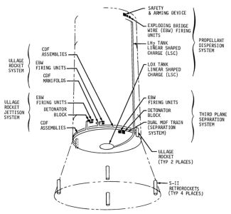
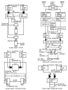
Ordnance
The S-IVB ordnance systems included the separation, ullage motor, ullage motor jettison, and propellant dispersion (flight termination) systems.
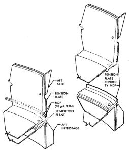
The third plane S-II/S-IVB separation system was located at the S-II/S-IVB interstage top. Third plane separation ordnance consisted of two EBW firing units, two EBW detonators, one detonator block assembly and a detonating fuse assembly. The EBW firing units were on the S-II/S-IVB interstage slightly below the third separation plane. The EBW firing unit leads were attached to EBW detonators installed in the detonator block assembly mounted just inside the vehicle skin, and the detonating fuse assembly ends were installed within the detonator block assembly. The detonating fuse assembly was mounted around the periphery of the vehicle beneath the tension strap. The two EBW firing units provided redundant signal paths for initiation of the detonating fuse assembly. Detonating fuse assembly detonation severed the tension strap attaching the S-II/S-IVB interstage at station 2746.5. At separation time four retrorocket motors mounted on the interstage structure below the separation plane fired to decelerate the S-Il stage; these are discussed in the S-II article.
 |
 |
 |
 |
| Ordnance Components |
Ordnance Systems |
Separation System |
Separation Joint |
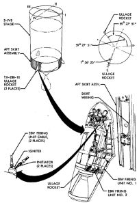
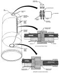
Two ullage motors generated a small acceleration to settle propellants and ensure stable flow of LOX and LH2 during J-2 engine start. The S-IVB ullage motor system consisted of two EBW firing units, two EBW detonators, two confined detonating fuse (CDF) manifolds, nine CDF assemblies, two separation blocks, four CDF initiators, and two ullage motors. The EBW firing units, EBW detonators, and CDF manifolds were mounted on the S-IVB aft skirt. The CDF assemblies connect the manifolds to the separation blocks and then to the CDF initiators. The ullage motors were within fairings mounted diametrically opposite each other on the S-IVB aft skirt. The motors were canted outward from the vehicle to reduce effects of exhaust impingement, and to reduce the resulting moment if one motor failed.
A separation block between the stage and each ullage motor allow motor jettison while maintaining CDF continuity. The inert separation block was located on the S-IVB aft skirt under skin under the ullage motor fairing. Each block consisted of an upper machined aluminum piece that held the CDF assembly ends to the initiators; the lower piece held the CDF assemblies from the manifolds. The separation block formed a connector that held the CDF assembly ends together to ensure propagation and to contain the detonation of the connection. At jettison, the block slipped apart with the lower portion remaining on the stage and the upper portion falling away with the motor and fairing.
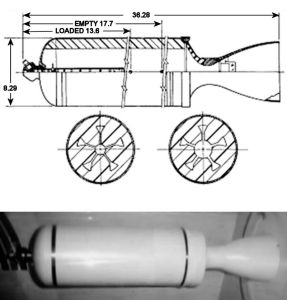
Each Thiokol Huntsville TX-280-10 ullage motor was 36.3" long, 8.3" in diameter and weighed 88.4 lb, 58.7 of which was a case-bonded solid propellant with a 5-point star grain. It produced 3,420 lbT for 3.81 seconds. The motor cases were from 4135 steel and a steel nozzle was also provided.
The ullage motor firing sequence began with the arming of the EBW firing units by charging the storage capacitors to 2,300 volts. At S-II engine shutdown, the EBW units receive a trigger signal that discharges the storage capacitors, releasing high energy pulses to the EBW detonators, and thereby exploding the bridgewires. The resulting detonations propagated through the CDF manifolds, CDF assemblies, separation blocks and to the CDF initiators which cause the ullage motors to ignite. A crossover CDF assembly between CDF manifolds provided redundancy and added system reliability.
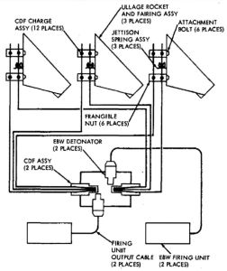
To reduce weight, the ullage motors and their fairings were jettisoned after J-2 engine start. The jettison system, located on the S-IVB aft skirt, used two EBW firing units, two EBW detonators, one detonator block, two CDF assemblies, four frangible nuts, and two spring-loaded jettison assemblies.
The EBW firing units were armed by charging their storage capacitors to 2,300 volts about five seconds after the S-IVB ullage motors stopped firing. A trigger signal released the high voltage pulse to explode the bridgewire in the EBW detonator. Either detonator could detonate both CDF assemblies through the detonator block. The detonation propagated through the CDF assemblies to detonate and fracture the frangible nuts. This freed the bolts that secured the ullage motors and fairing assemblies to the aft skirt. The spring loaded jettison assemblies propelled the spent motor and fairing assemblies away from the vehicle.
S-IVB Ullage Motor System
 |
 |
 |
 |
| Component Installation |
Jettison Components |
Jettison System |
TX-280-10 Motor |
Propellant Dispersion System |
The S-IVB propellant dispersion system (PDS) terminated vehicle flight during the first engine firing boost burn if the vehicle flight path varied beyond its prescribed limits or if continuation of vehicle flight created a safety hazard. The PDS could be safed after the launch escape tower was jettisoned. The system was installed in compliance with Air Force Eastern Test Range (AFETR) Regulation 127-9 and AFETR Safety Manual 127-1. The S-IVB PDS was a dual channel, parallel redundant system composed of a radio frequency segment that received, decoded and controlled the propellant dispersion commands, and an ordnance train segment consisting of two EBW firing units, two EBW detonators, one safety and arming device (shared by both channels), seven CDF assemblies, two CDF tees, and three linear shaped charge assemblies. If emergency termination become necessary, two coded messages were transmitted to the launch vehicle by the range safety officer. The first command armed the EBW firing units and initiated S-IVB stage engine cutoff. The second command, delayed to permit charging of the EBW firing units, discharged the storage capacitors across the exploding bridgewires in the EBW detonators. The resulting explosive wave propagated through the ordnance train to linear shaped charges for the LH2 and LOX tanks. The shaped charges were RDX loaded at 150 grains per foot. Two assemblies cut two 20.2-foot long parallel openings in the LH2 tank side. One assembly cut a 47" diameter hole in LOX tank bottom. Following S-IVB engine cutoff the PDS was electrically safed by a ground command.
References
Bauer, H.E. Operational Experiences on the Saturn V S-IVB Stage (Huntington Beach, California: McDonnell Douglas Astronautics Co. Western Division, Saturn/Apollo Programs, 1968)
Bilstein, Roger E. Stages to Saturn NASA SP-4206 (Washington, DC: NASA History Office, 1996).
Hunley, J.D. Technology for U.S. Space-Launch Vehicles, 1926 – 1991 (College Station, TX: Texas A&M University Press, 2007).
Saturn V Flight Manual, SA-503 (Apollo 8), MSFC-MAN-503 (MSFC, Alabama: MSFC, 1 Nov 1968).
Saturn V Flight Manual, SA-507 (Apollo 12), MSFC-MAN-507 (MSFC, Alabama: MSFC, 15 Aug 1969).
Skylab Saturn IB Flight Manual, MSFC-MAN-206 (Huntsville, AL: Marshall Space Flight Center, 30 Sep 1972).
--- On To Part 8.31 - The Saturn Instrument Unit ---