U.S. Manned Rocket Propulsion Evolution
Part 8.00: The Saturn V
Compiled by Kimble D. McCutcheon
Published 1 Apr 2021; Revised 3 Aug 2022
USSRC
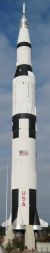
Saturn V
Replica |
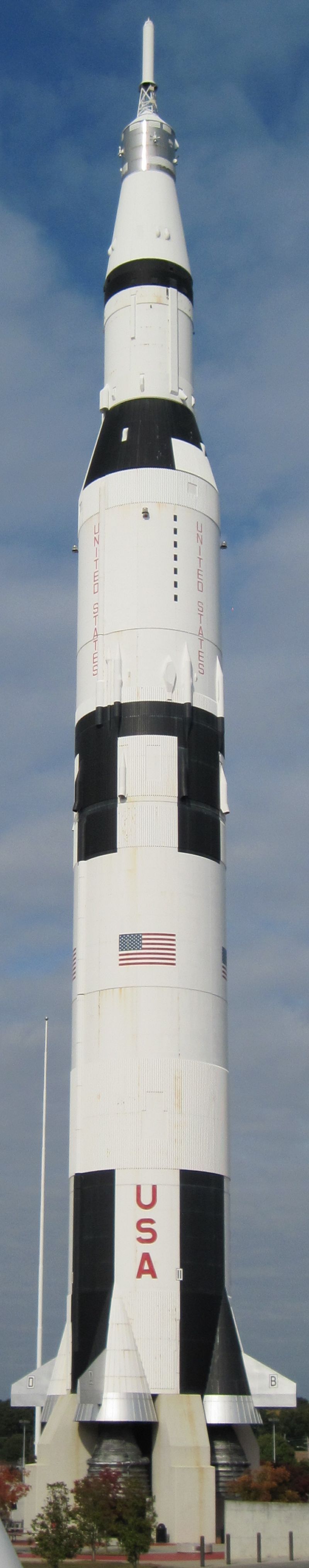
Of the thirteen Saturn V rockets were launched, ten were crewed. Eight missions entered lunar orbit and six of these landed humans on the moon. A ninth mission, Apollo 13, journeyed to the moon but did not enter orbit or land. Of the three uncrewed launches, two were tests and the last launched Skylab, which was the first U.S. Space Station.
This series will cover the propulsion used by Saturn V's stages and components, but before we embark on that exploration, this article will serve to reacquaint readers with the Saturn V, its stages, its components, and an overview of how they all worked together. |
The USSRC Saturn Vs
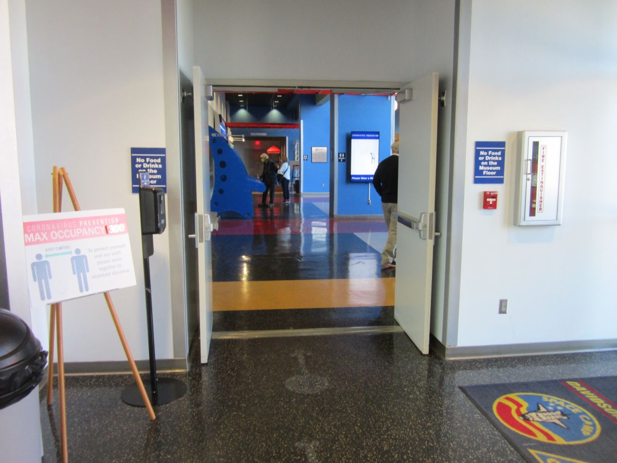
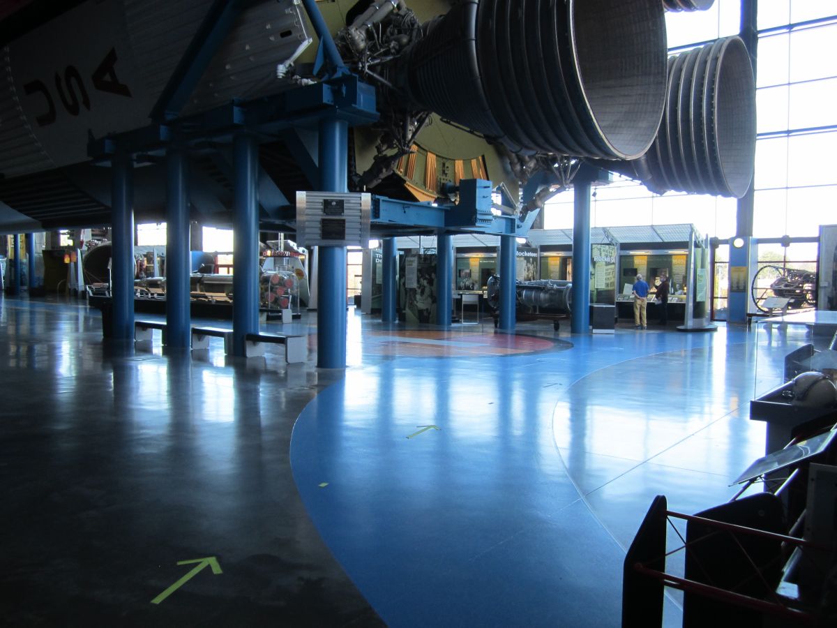
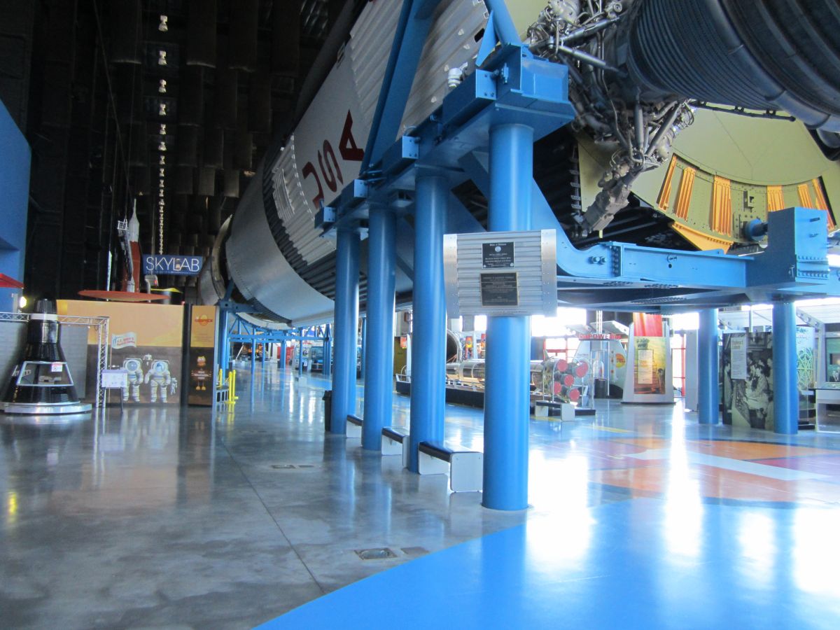
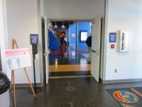
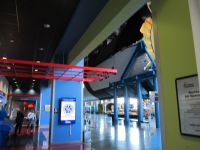
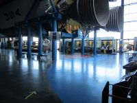
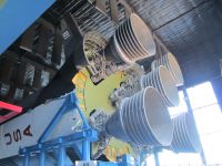
As a volunteer docent at the U.S. Space and Rocket Center (USSRC) in Huntsville, Alabama, I get to spend a lot of time around one of the three remaining Saturn V rockets; the other two are in Florida and Texas. The Saturn V is nothing if not huge and I’m often amused at people’s reactions when they see if for the first time. Housed in the Saturn V Hall, part of the Davidson Center for Space Exploration, it is displayed about 10 feet above USSRC guests, who have probably already seen photographs and certainly seen the 363-foot-tall full-scale replica just outside in the Apollo Courtyard. But none of this prepares them for their first encounter with the real thing. To enter the Saturn V Hall, guests must climb a spiral staircase or take an elevator to the Davidson Center's second level and go through double doors in the corner of the Hall. Their sight line is usually level with the floor, so they first see a huge room full of artifacts. Then they start to realize there is something profound above eye level as they take in the 33-foot diameter Saturn V first stage base with its 5 massive F-1 engines and 62-foot fin span. Then the funny part — their heads start to move up and up, but their chins stay where they were, and they stand, mouths agape at the spectacle before them. This is a universal reaction regardless of whether the guest is young or old, naive or sophisticated, international or local.
 |
 |
 |
 |
 |
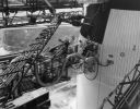
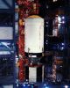
| Entry into the USSRC Davidson Center Saturn V Hall |
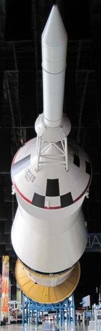
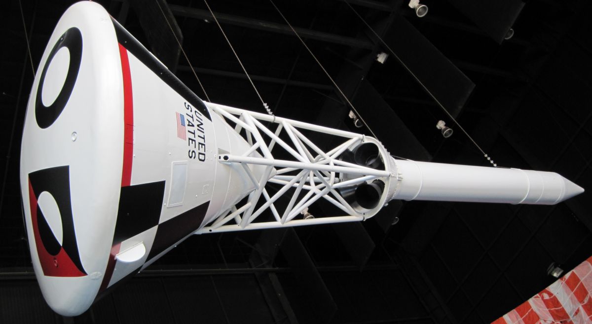
Apollo LES, CM, SM, SLA |

Apollo CM, LES |
Saturn V Components |
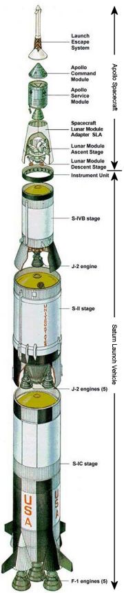
Two main assemblies comprise the Saturn V rocket — the Saturn V Launch Vehicle (LV) and the Apollo Spacecraft (SC). The Launch Vehicle consists of three rocket stages and an Instrument Unit. For historical reasons, the stages are named, from bottom to top, S-IC (pronounced S one C), S-II (pronounced S two), and S-IVB (pronounced S four B). The Instrument Unit (IU) is mounted just above the S-IVB stage. The Apollo Spacecraft, that part that goes to the moon, consist of the Lunar Module (LM) housed within a Spacecraft/Lunar Module Adapter (SLA), Service Module (SM), Command Module (CM) and Launch Escape System (LES). The Launch Vehicle has the job of getting the whole shebang off the earth and pointing the Apollo Spacecraft, which weighs about 100,000 lb, toward where the moon will be in three days and accelerating it to a velocity of nearly 25,000 mph, which is fast enough to get it to a point where the moon’s gravitational influence exceeds that of earth. The Apollo Spacecraft makes the lunar voyage, lands on the moon, and returns the Command Module safely to earth.
The Saturn V on display at the USSRC has more original parts than those in Florida and Texas, which were assembled for display from components left over from the Apollo program. The USSRC Saturn V, designated SA-500D/F, was purpose-built as a dynamic test article. It was named SA-500D/F because it was made up of components intended solely for dynamic testing as well as components previously in the SA-500-F, more about which later.
In the 1960s, accurately predicting the behavior of large, flexible structures, such as big rockets, was a nearly impossible task. Although crude (by today's standards) analytical models existed the fidelity of these models was suspect. The 1960s-era engineers only had one way to verify a rockets' vibration and bending behavior —build a full-sized version, load it and shake it.
SA-500D/F's stage 1, known as S-IC-D was the first S-IC built by Boeing at NASA's Michoud Assembly Facility near New Orleans, Louisiana. It had one "nearly real" F-1 engine and four mass simulators with the same mass and center of gravity as real engines. Boeing and Marshall Space Flight Center (MSFC) engineers had collaborated to build three prior S-IC test articles (S-IC-T, S-IC-S and S-1C-F) and two flight articles (S-IC-1 and S-IC-2). S-IC-T was a static test article that proved the complete stage with all engines and systems running. S-IC-S was a structural test article. S-IC-F was used to verify launch facilities, transportation and logistics; it was also used to train launch crews, develop test and checkout procedures.
Stage 2, built by North American Aviation and known as S-II-F/D, first served as part of the SA-500F facilities checkout stack at Kennedy Space Center, after which it was transported to MSFC to become part of SA-500D/F.
Stage 3, built by Douglas Aircraft and known as S-IVB-D, served as a second-stage Saturn I dynamic test article as well as the SA-500D/F third stage dynamic test article.
TheSA-500D/F Instrument Unit, built by International Business Machines and known as S-IU-200D/500D, also served a dual role during Saturn I and SA-500D/F/F dynamic tests.
Topping out SA-500D/F is a boilerplate Apollo spacecraft, consisting of BP-23A and LTA-2. BP-23A consisted (top to bottom) of a launch escape system, a command module, a service module (SM-10) and a SLA (SLA # 1). BP-23A filled the role of actual flight hardware, having the same shape, mass and center of gravity as the actual LES, CM, SM, and SLA. BP-23A's command module was flown twice during testing of the launch escape system and retains its peculiar paint scheme that allows identification of its orientation during flight.
Dynamic Testing
The components previously described were assembled in the specially-built Saturn V dynamic test stand, which was fitted with numerous hydraulic and electrodynamic shakers capable of simulating the lateral, longitudinal and torsional excitation and bending loads to which the vehicle would be subjected. The collected data verified analytical analyses and was used to design structural, guidance and flight controls systems.
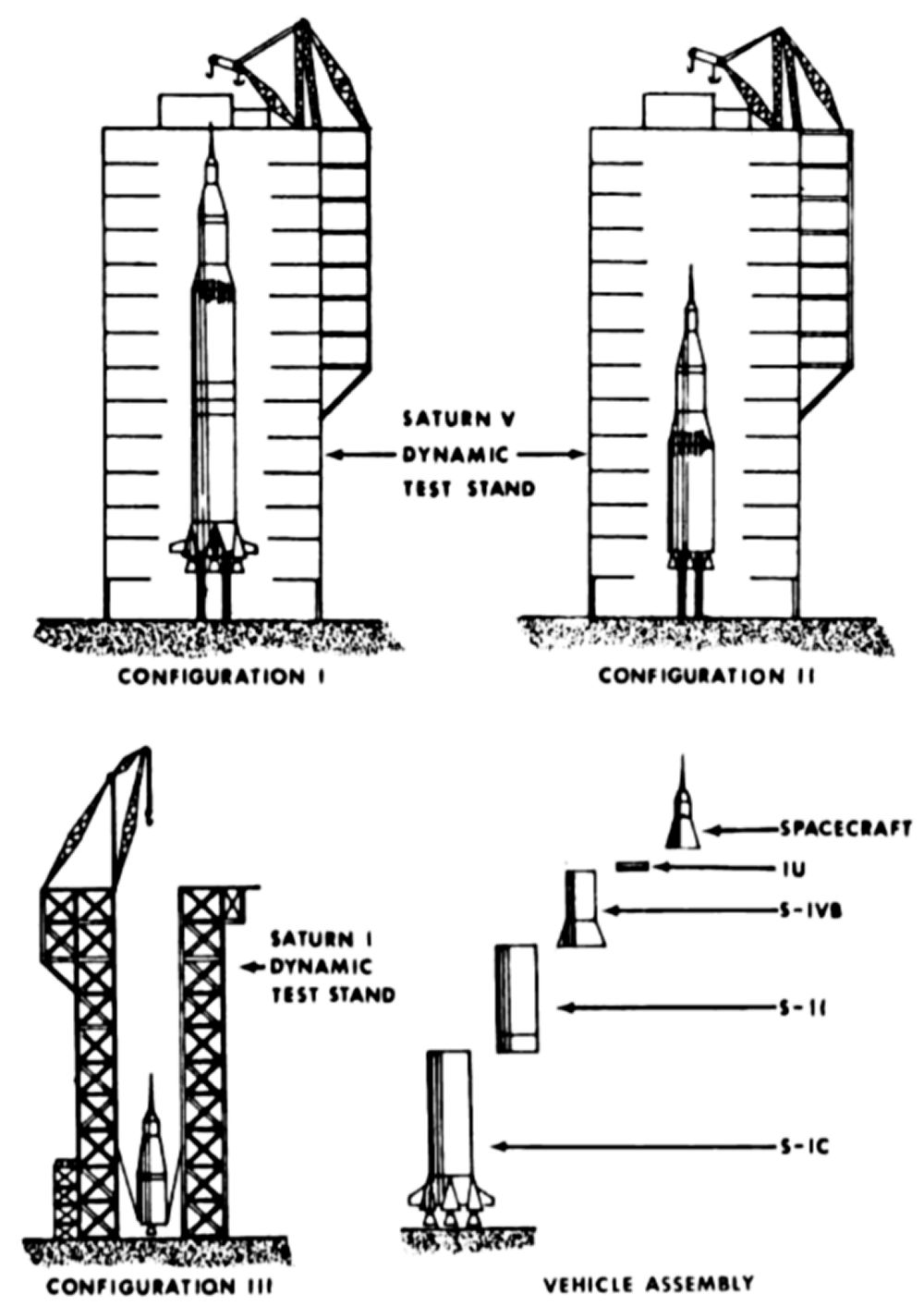
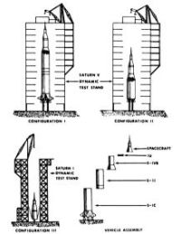
Three configurations were tested at varying fuel loads: Configuration I evaluated the entire stack as it would be when launched; Configuration II evaluated the stack still remaining after stage 1 was jettisoned; Configuration III evaluated stage 3 and the Apollo spacecraft. This dynamic testing transpired from January through August 1967. All this testing took 450 hours and gathered data from over 800 points. SA-500D/F is designated a National Historic Landmark as well as a National Mechanical Engineering Landmark.
 |
 |
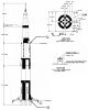
| Dynamic Testing Configurations |
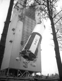
S-IC-D Being Hoisted into
the MSFC Dynamic Test Stand |
How Astronauts Got to the Moon and Back
The Saturn V rocket was designed to include 91 thrust-producing devices including liquid-propellant rocket engines, solid rocket motors, and attitude control thrusters. Not all of these were used on every flight; as the engineering team gained experience with the rocket some of them were omitted.
The S-IC first stage with its over 7.5 M lbT got the fully-fueled Saturn V stack weighing a bit less than 6.5 M lb off the earth. Note that each F-1 engine produced 1.5 M lbT so if one failed early in the flight, there was no longer enough total thrust to lift the rocket. This is one reason for the LES — to snatch the Apollo capsule and its occupants away from impending doom. The S-IC burned RP-1 and LOX, was 138 feet tall, 33 feet in diameter and weighed about 300,000 lb empty. When loaded with RP-1 and LOX it weighed a bit less than 5 M lb. It burned for about 160 seconds and at the end of its burn, had lofted the rocket to an altitude of about 40 miles and achieved a velocity of about 6,000 mph. At the end of its burn, pyrotechnic straps that joined the S-IC to the S-II stage fired and broke the bond between the two stages. Simultaneous to this, eight retro rockets fired at the S-IC base to aid in stage separation before the second stage engines started.
The S-II second stage, using five J-2 engines burning liquid hydrogen (LH2) and LOX, produced about 1.1M lbT and burned for about six minutes. It was 81 feet 7 inches tall, 33 feet in diameter and weighed about 95,000 lb empty. Loaded with fuel, it weighed about 1.04 M lb. At the end of its burn the S-II stage had lofted the rocket to an altitude of about 115 miles and a velocity of about 15,500 mph. After its separation from the S-IC stage, the S-II stage coasted upward and was essentially weightless, allowing the propellants to wander around their tanks, perhaps out of contact with the engine feed lines. The S-II stage used up to eight (usually four) solid propellant ullage motors to create an acceleration that settled the propellants to the tank bottoms. These ullage motors were mounted outside the S-II stage aft skirt, which was jettisoned after the ullage motors had fired. The S-II stage also had four solid-propellant retro rockets that fired during S-II/S-IVB staging.
The S-IVB third stage burned twice. It was also fitted with two solid-propellant ullage motors that settled its propellants prior to the first burn. The S-IVB, with a single J-2 LH2/LOX engine producing 230,000 lbT, was 58 feet 7 inches tall, had a 21 foot 7 inch diameter, and weighed 33,600 lb empty; loaded with propellant it weighed 265,600 lb. Its first burn of 2.75 minutes achieved a circular earth orbit with an altitude of about 115 miles and a speed of 17,500 mph. After at least 1.5 orbits, and after a thorough checkout of the spacecraft and all systems, the S-IVB stage fired two liquid-fueled thrusters to settle its propellant and then restarted the J-2, when burned for about 5.3 minutes. This burn was initiated and timed to enter lunar orbit when the spacecraft reached the moon about three days later. Speed at the end of this translunar injection (TLI) burn was about 24,500 mph.
Transposition, Docking and Ejection (TD&E)
About 30 minutes after TLI the CM Pilot began thrusting forward for about two seconds, pressed the CM/LV Sep pushbutton to separate the spacecraft from S-IVB and continued thrusting forward for another few seconds. The CSM/SLA separation process was rapid but complex. Linear explosives severed electrical connections and cut the metal bands retaining the SM to the SLA. Similar explosives freed the four conical SLA segments near their tops, allowing the spring-loaded partial hinges at the segments' lower edge centers in conjunction with pyrotechnic thrusters to rotate the segments outboard about 45°, disengaging the hinges and jettisoning the panels. The LM was then exposed on top of the S-IVB. The CSM moved forward 50 to 75 feet, pitched backwards 180°, rolled to align with the LM docking target, and then moved back to the LM to dock. Once docking was successful, more explosive hold-down bands released the LM from the S-IVB and springs separated the LM from the S-IVB.
The spacecraft then briefly fired its Service Propulsion System (SPS) engine and the S-IVB dumped its residual fuel through propulsive vents. These actions ensured separation between the spacecraft and S-IVB for the remainder of the mission.
All Saturn V guidance and control up to this point had been achieved by the Launch Vehicle Digital Computer (LVDC), located in the Instrument Unit (IU) atop the S-IVB just below the SLA. This is not a trivial accomplishment, for the LVDC successfully steered the launch vehicle despite four hardware configurations, with full propellant tanks that drain to empty, and with varying vehicle bending and vibration modes, all dependant upon configuration, vehicle center of gravity and mass. This was done with only 112 kilobytes of random access memory, which was used to store both programs and data! From this point forward guidance and control would be accomplished by two Apollo Guidance Computers (AGC), one in the CM and one in the LM. The two AGCs use identical hardware but use different software to acquire data from the respective spacecraft and control their respective systems. The AGCs each had only 36,864 16-bit words of read-only memory and 2,048 words of random access memory. With these scant resources the AGC performed the guidance and navigation problem, monitored and controlled the engines, reaction control system thrusters, and responded to crew requests and control inputs.
 |
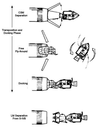 |
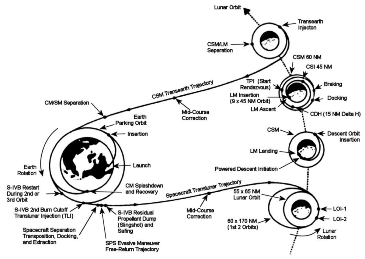
| Apollo Mission Profile |
Transposition, Docking and Ejection |
Translunar Coast, Lunar Orbit, Lunar Landing and Return to Earth
Once TD&E was complete, the spacecraft settled down for a 2.5 – 3.5 day coast to the moon, rolling slowly about twice per hour to maintain even solar heating. As the spacecraft traveled it slowed until it eventually reached a point where lunar gravity exceeded earth gravity. During its translunar trajectory the spacecraft might stop its rotation up to four times to do star sightings, update the inertial guidance units, and possibly perform mid-course corrections, which involved short burns of the Service Module Propulsion System (SPS) for large course changes or the SM reaction control system (RCS) for small corrections.
When the spacecraft reached the moon it performed an SPS braking burn for Lunar Orbit Insertion (LOI) that reduces its velocity from around 5,600 mph to about 3,600 mph. The initial SPS burn put the CSM into a 70 x 195 mile orbit; a second LOI burn achieved a 70-mile circular lunar orbit. The precise timing of LOI burn initiation and duration were calculated by ground control and programmed into the CM AGC, which automatically fired the SPS engine.
Once in lunar orbit, the spacecraft coasted as the LM was checked out in preparation for descent to the lunar surface.
The CM-LM tunnel and LM were pressurized, the CM hatch, docking probe and drogue were removed and stowed in the CM, clearing a path for astronauts into the LM. The LM pilot went first and activated the LM electrical power, environmental control and communication subsystems. The LM commander then entered the LM and the two worked together performing a lengthy series of checks on the LM.
When the LM was ready to descend to the moon, the drogue and probe were reinstalled, the LM hatch closed, the CM hatch is installed, and the 12 docking latches unlatched, . The LM landing gear was deployed and the CM pilot extended the probe, which undocked the LM. The LM pilot used the LM RCS to move the LM away from the CSM far enough for the CM pilot to inspect the LM landing gear, making sure it was correctly deployed.
While the CSM stayed in its 70-mile lunar orbit, the LM used its RCS thrusters to increase its distance from the CSM. The LM descent took about an hour and began when it fired its descent engine to establish an elliptical orbit that ranged from 70 miles to about 50,000 feet. The LM descent engine fired again to reduce the LM's speed. At an altitude of about 9,000 ft another automatic descent engine firing brought the craft to an altitude of about 500 ft. At this point the crew could see and assess the landing site. At about 65 ft the LM was oriented vertically and descended to the moon's surface at about 3 fps. An indicator light marked landing gear contact at which time the LM commander shut off the descent engine.
The crew again checked out the LM, aligned the inertial measurement unit, and prepared the extravehicular mobility back packs for use. The LM cabin was depressurized and the crew climbed down a ladder to the lunar surface where they planted flags, performed experiments, hit golf balls, dropped hammers and explored. A lunar roving vehicle allowed the crew to travel up to 5 km from the touchdown point during the later three missions.
When work on the moon was complete, the crew reentered the LM and prepared for ascent, CSM rendezvous and docking. This process took about three hours. When the LM ascent engine ignited the LM ascent stage separated from the descent stage and achieved an elliptical orbit, followed by a circular orbit that was a constant altitude distance from the CSM. The LM AGC fired the LM RCS to intercept the CSM. The LM commander then took over manual control and docked with the CSM.
The docked LM and CSM then coasted in lunar orbit while the crew prepared for return to earth. CSM and LM pressures were equalized and the LM crew opened the LM tunnel hatch. Again, the CM pilot removed the CM tunnel hatch, probe and drogue. The probe and drogue were this time stowed in the LM. Lunar samples, film and equipment headed back to earth were moved to the CM. Equipment in the CM that was no longer needed was stowed in the LM. The LM hatch was closed, the CM hatch replaced and its seal checked. The LM was jettisoned by firing small pyrotechnic charges around the docking ring, which separated the entire docking mechanism, which was still attached to the LM. The SM RCS then moved the CSM a safe distance away from the LM ascent stage.
At the appropriate point in the CSM's lunar orbit the AGC fired the SPS engine to attain a trajectory that would return to earth. This involved a burn of about 2.5 minutes that accelerated the CSM from 3,600 mph to nearly 5,500 mph. As with all other SPS burns that had occurred near the moon, this one occurred when the CSM was behind the moon, out of radio contact with the earth.
The transearth coast that followed may have required 80 to 110 hours as the CSM's velocity gradually decreased until the earth's gravitational influence became predominant, at which time it started to accelerate until the CM entered the earth's atmosphere at about 25,000 mph. During this coast the CSM again slowly rolled for thermal control and made any necessary mid-course corrections.
About 3.5 hours before reentry the CSM maneuvered to put the pointy end of the CM in shadow, thereby chilling the forward heat shield before reentry. Shortly before reentry the SM was jettisoned using small pyrotechnic charges in the SM. Simultaneously the SM RCS thrusters fired, ensuring separation between the two modules as they reentered the earth's atmosphere.
Atmospheric entry began at an altitude of about 400,000 ft. The CM, traveling at about 24,500 mph, generated atmospheric heating of up to 5,000°F at the aft heat shield. The heat shield surface ablated, carrying away the reentry heat and keeping the CM's interior at about 80°F. The astronauts experienced a deceleration of about 5 g. Because the CM's center of gravity did not coincide with its center of pressure, the CM's reentry path could be altered by rolling the CM.
At about 24,000 ft a barometric switch jettisoned the forward heat shield and deployed the drogue parachutes, which oriented the CM for main parachute deployment and slowed its velocity from about 325 mph to about 125 mph. The three main parachutes started to deploy at about 10,700 ft. When fully open they slowed the CM to about 22 mph.
During the last five minutes before splashdown the crew burned the remaining reaction control propellant, activated the recovery beacon, deployed the communication antennas, adjusted their couches for landing and purged the propellant lines. At splashdown, the crew jettisoned the main parachutes, deployed CM flotation bags to keep it upright and activated post-landing ventilation. Then they waited to be picked up by Navy helicopters.
There and Back Again
We have explored in very general terms the process by which a 6.5 million pound rocket conveyed three men to the earth's moon and returned them safely back to earth in capsule weighing but 11,200 lb. This is an extraordinary accomplishment by any measure. However, this brief account belies the incredible effort required to plan and execute the moon landings. Over 400,000 persons of every skill set imaginable worked for over 20,000 organizations to accomplish this from concept to completion in under a decade. No other human endeavor before or since holds a candle to putting the first human on the moon.
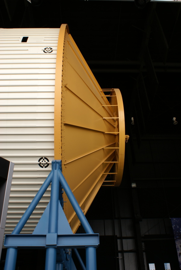
Markings
Each Saturn V stage is painted and marked in a way that provides a unique presentation from every viewing angle. This black-on-white paint pattern facilitates vehicle orientation identification from any image, including film frames.
In addition, there are numerous legends, instructions, camera targets and other nomenclature that identify many exterior stage features.
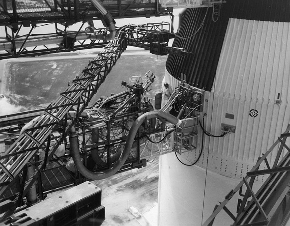
Camera targets were apparently only present on AS-500F (the S-II stage of which appears at the USSRC) and AS-501 (Apollo 4). AS-502 and subsequent do not appear to have the targets. These targets may have been used to help with early stage alignment exercises in the Kennedy Space Center Vehicle Assembly Building.
Saturn V Stage Markings (heroicrelics.org)
 |
 |
 |
 |
 |
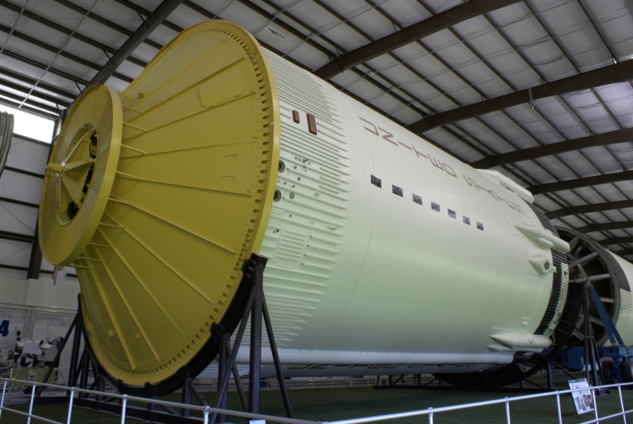
S-II
at KSC |
AS-500
at KSC |
AS-501
at KSC |
AS-500F
at USSRC |
Camera
Target |
References
Bilstein, Roger E. Stages to Saturn NASA SP-4206 (Washington, DC: NASA History Office, 1996)
Apollo 11 Lunar Landing Mission Press Kit (Washington, DC: NASA) 6 Jun 1969.
https://www.apollomaniacs.com/apollo/saturnv_menu_e.htm
https://heroicrelics.org/
https://en.wikipedia.org/wiki/Saturn_V_dynamic_test_vehicle
--- On To Part 8.10 ---