U.S. Manned Rocket Propulsion Evolution
Part 2.2: V-2 Propulsion
Compiled by Kimble D. McCutcheon
Published 1 Nov 2020; Revised 16 Jan 2024
V-2 Propulsion Engineering Challenges
| The V-2 was a huge step forward from the A5. In order to achieve its goal of delivering a 2,200 lb warhead 200 miles away, the missile had to be substantially larger. It now needed to generate about 55,000 lbT (25 metric tons, leading to it being called the 25-Ton engine) and run for more than a minute. This was an over 16-fold thrust increase over the A5, plus a 33% burn time increase. This was to be accomplished by burning huge quantities of propellant at much higher chamber pressure that with earlier rocket engines. This required high-pressure pumps instead of the earlier pressure-fed scheme. Pressure-fed rockets are fine as long as they are small and relatively low performance. However, once the size reaches a certain point, it is better to invest in the additional weight and complexity of pumps to get the propellants into the thrust chamber. The design of pumps and thrust chamber capable of producing the needed thrust was a major V-2 engineering challenge. | |
|
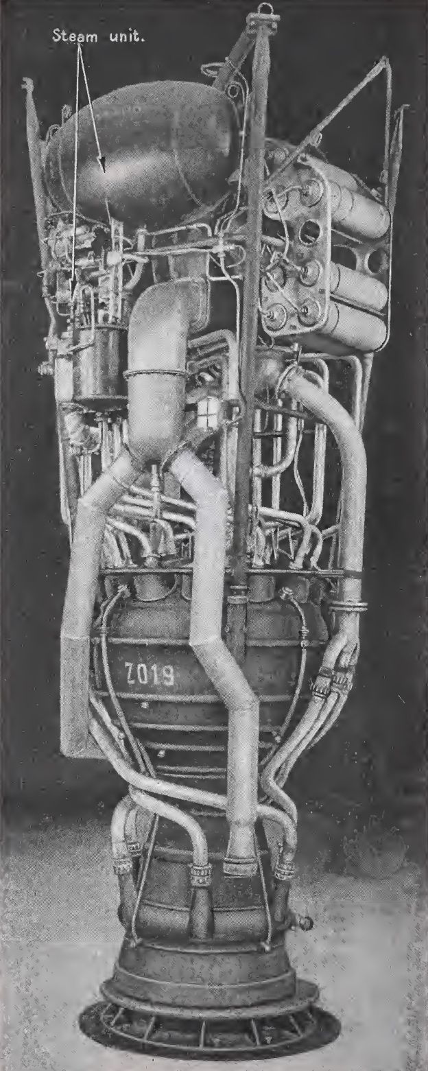
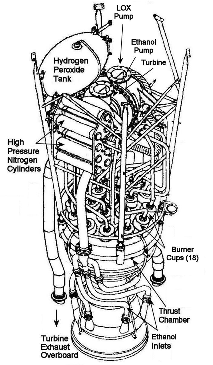
| V-2 Power Plant | V-2 Power Plant Schematic |
 |
 |
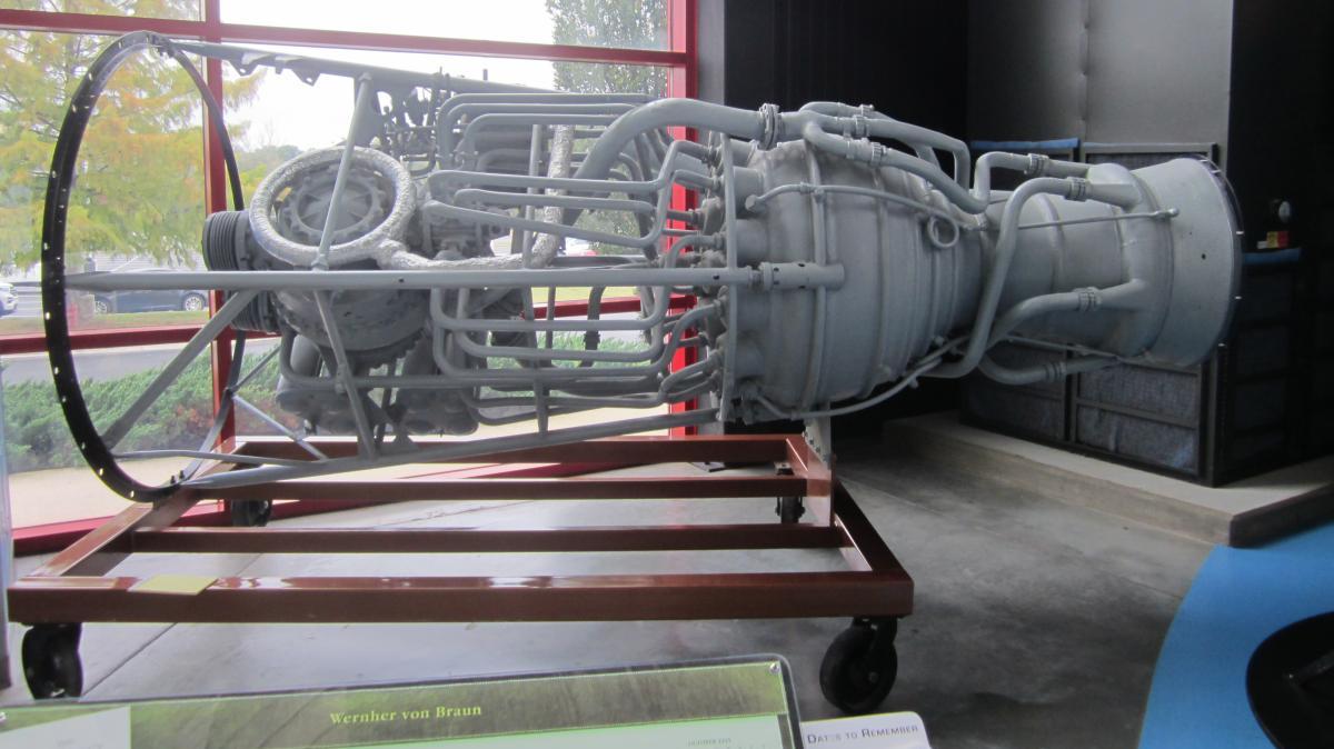 |
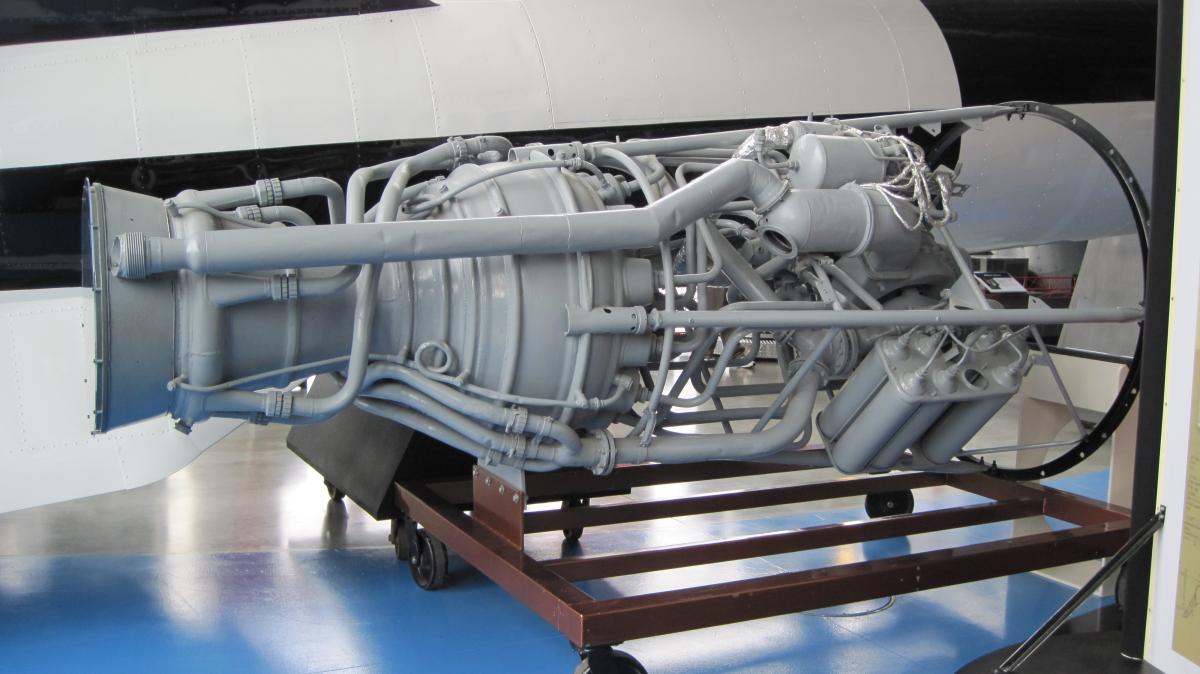
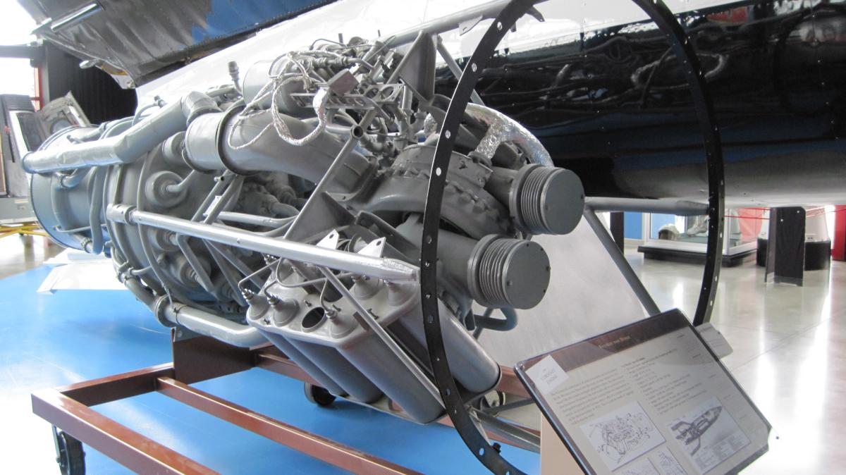
| V-2 Power Plant at the U.S. Space & Rocket Center. The Peroxide Tank is Missing. | ||
The V-2 Thrust Chamber
The von Braun team had already encountered numerous development problems such as thrust chamber burn throughs, explosions, fires, frozen valves and unreliable electrical components. Developing the V-2 thrust chamber would be no different.
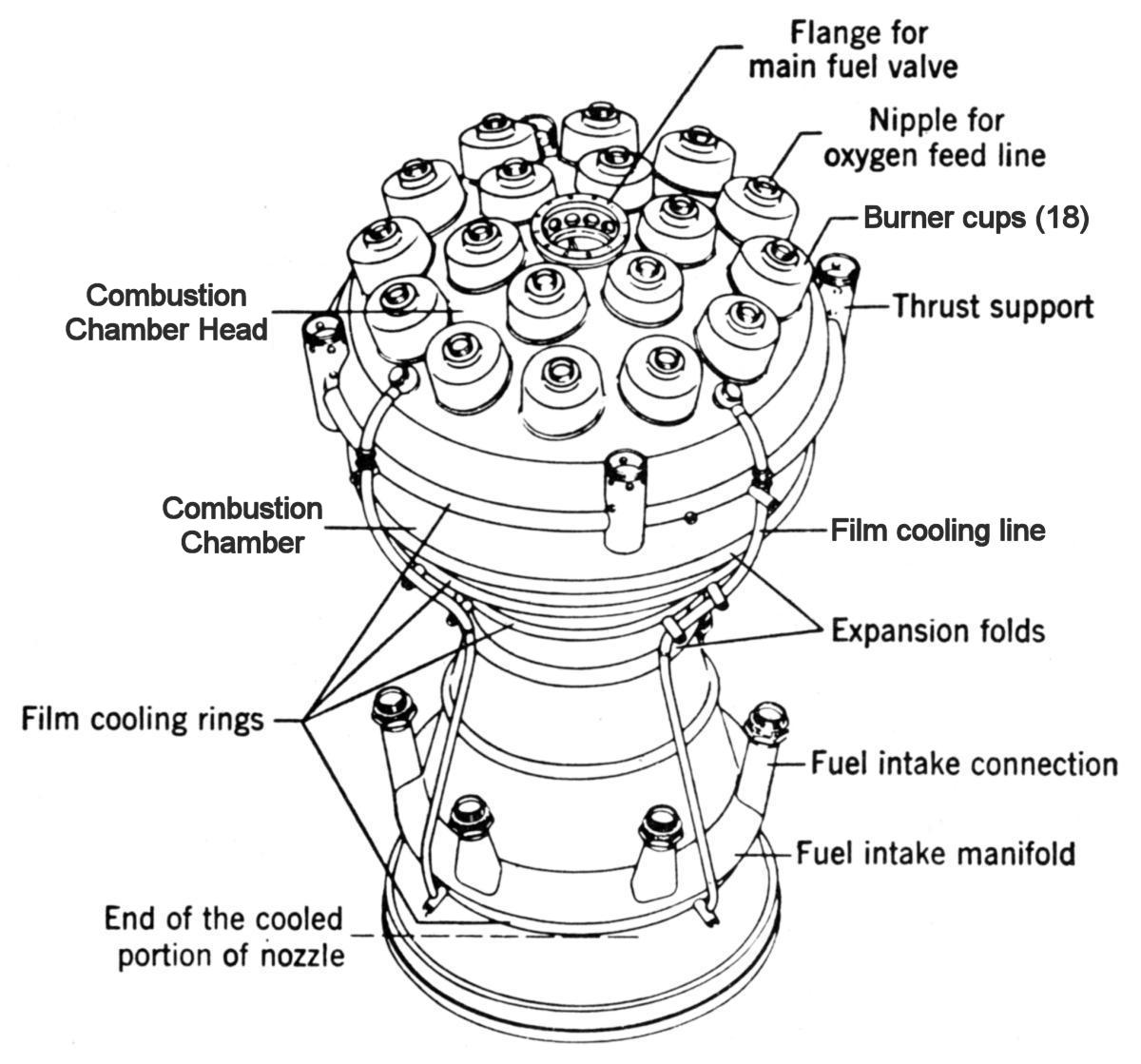
Walter Thiel was hired for the job. His observation that poor combustion was reducing engine efficiency led to shortening the combustion chamber into a sphere, which had the maximum volume to surface area. Previous designers had believed a long combustion chamber gave the propellants more time to mix and burn completely. Thiel also increased chamber pressure and improved injectors to achieve better mixing and better combustion. Thiel's initial work was on smaller engines. In order to keep the combustion process stable in the 25-Ton engine, he used 18 of the small engine injectors (burner cups) arranged in concentric circles around the top on the spherical combustion chamber's head element.
Professor Wewerka of the Technical Institute in Stuttgart contributed to nozzle design, establishing that the ideal nozzle expansion ratio was about 0.75 and that the ideal half-cone divergent angle was 15°.
To cool the big engine, Thiel employed a combination of regenerative and film cooling. The 75% ethanol fuel entered the double-walled thrust chamber near the nozzle bottom via six pipes, made its way through the double-walled nozzle and combustion chamber to the top where the main fuel valve routed it to the fuel injectors. The film cooling was achieved via four circumferential manifolds placed at strategic locations along the thrust chamber length. Small holes drilled in the thrust chamber inner wall oozed about 3% of the fuel, which vaporized into a protective boundary layer that hugged the thrust chamber inner walls.
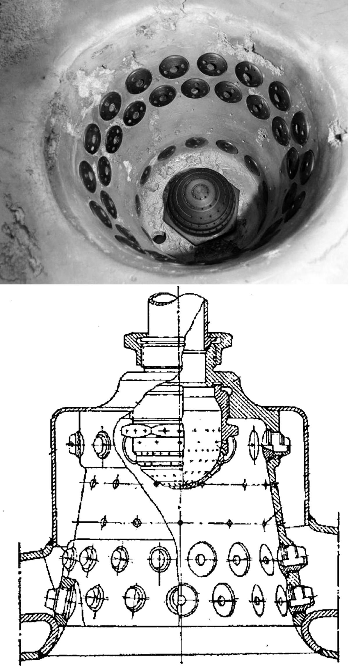
The thrust chamber used no exotic materials. The inner and outer walls were welded up from steel pressings. Each burner cup had a central brass LOX injector into which 120 holes had been drilled. Surrounding the LOX injector in three circles were 68 alcohol injectors that were screwed into the burner cup inner wall. The team hoped to put a thrust chamber with a single large injector into service, but it could not be perfected in time for production deadlines. [Hunley]
 |
 |
 |
.jpg) |
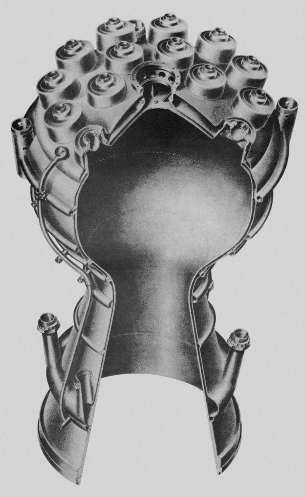
| V-2 Model 39 Thrust Chamber. Clearly visible is the double-wall construction, rows of film cooling holes, and tubes supplying the film cooling manifolds from the thrust chamber head. Also visible within the head is the fuel passage leading to the main fuel valve seat and the fuel manifold serving the 18 burner cups. Note the intricate machining and welding required. | V-2 Thrust Chamber External Features | V-2 Burner Cup Interior and Section | Experimental Single-Injector V-2 Model 39a Thrust Chamber, Never Entered Production |
The Turbopump
In mid-1935, von Braun began looking for pump expertise that could help develop the very demanding V-2 turbopump. The firm Klein, Schanzlin & Becker (KSB), a manufacturer of fire-fighting equipment centrifugal pumps, turned out to be the ideal candidate. Similarly, von Braun brought Helmuth Walter's engineering firm on board to develop a steam turbine for driving the pumps; this technology was based on Walter's scheme for a steam torpedo propulsion package.
The turbopump was a very challenging development problem. Not only did it have to be light in weight, but it also had to pump large volumes of propellant at high pressure. It had to do these things within a device that was pumping ethanol at ambient temperature, LOX at -297°F, while sealing both fluids from each other and the 725°F high-pressure steam. These temperature differentials tended to warp the turbopump. Another problem arose in the requirement to pump the propellants, and in particular the LOX, without cavitation because bubbles in the propellants caused uneven engine performance; this was solved by controlling the pressure in propellant tanks and cross section of pump impellers and diffusers.
Once KSB and Walter had provided the initial equipment, the von Braun team at Peenemünde undertook the task of integrating the components and making them work together.
Special seals and gaskets had to be developed for use around LOX, along with special cleaning procedures for all equipment that camp in contact with it. Even a single stray finger print left on a surface exposed to pressurized LOX could create an explosion.
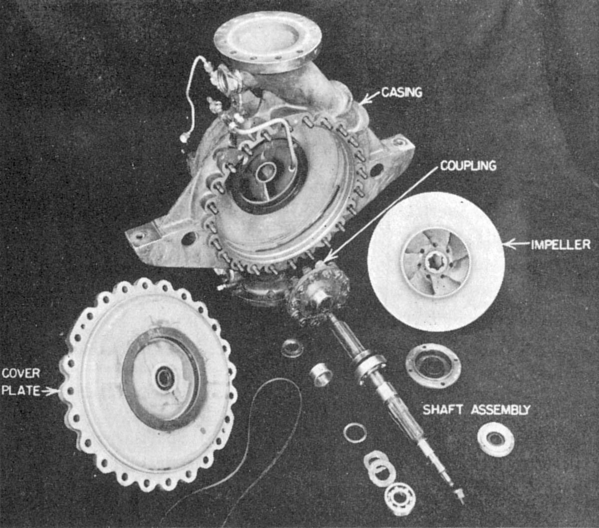
Gradually the turbopump team developed bearings that could be lubricated with the fluids being pumped. These were ball bearings for the fuel pump and plain bearings for the LOX pump.
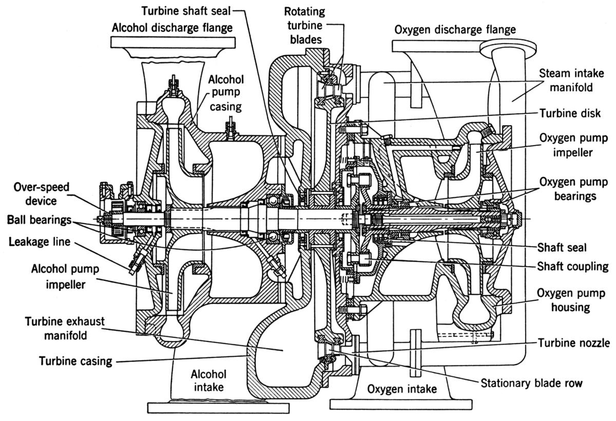
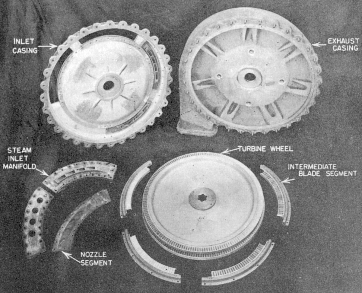
The final design comprised a two-stage impulse steam turbine, nominally operating at 3,800 to 4,900 rpm, fed by three cast iron steam nozzles and running on ball bearings. The fuel pump was splined to one side of the turbine, and the LOX pump attached to the opposite side via a flexible coupling. Shaft seals kept all the fluids where they belonged, and each pump had a leakage line that routed any leaked fuel or LOX overboard. The fuel pump was equipped with a speed sensor that shut down the engine if turbine rpm exceeded 5,000. Choke rings were fitted to the fuel and oxidizer outlets to calibrate the relative outputs of individual pumps, ensuring correct mixture ratio despite turbopump manufacturing tolerances. [Hunley, The V-2 Turbopump (https://www.youtube.com/watch?v=EgiMu8A3pi0)]
 |
 |
 |
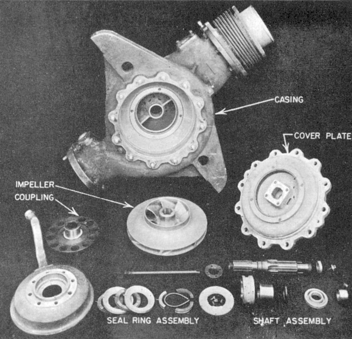 |
| V-2 Turbopump Longitudinal Cross Section | V-2 Turbopump Turbine | V-2 Turbopump Fuel Pump | V-2 Turbopump LOX Pump |
 |
 |
 |
 |
 |
| Fuel Pump Outlet Choke | LOX Pump Outlet Choke | Main LOX Valve and LOX Distrubution (18) |
Fuel Splits Two Ways | Fuel Then Splits Three Ways |
The Steam Plant
The V-2 turbopump turbine was powered by steam obtained by catalyzing 85% hydrogen peroxide with, depending on whom you believe, calcium, potassium or sodium permanganate dissolved in water. This reaction produced hot, high-pressure steam and free oxygen that was fed to the steam turbine via a steel tube sheathed in asbestos. The peroxide and permanganate mixed in the steam generator, whose interior included baffles and spirals that ensured good mixing of the two. Valves, valve controls, gages, etc. that were commercially available could not handle the fluids and/or pressures, or were too heavy. A special laboratory at Peenemünde was dedicated to valve development, which was fortuitous, because the steam plant employed several specialized valves to start, run and stop the engine. Chief among these were the 25-Ton valve and the 8-Ton valve. When only the 8-Ton valve was opened, turbopump output was limited so that the engine only produced a thrust of 8 metric tons. When both the 8-Ton and 25-Ton valves were opened, the turbopump ran at full speed, pumping enough propellant so the engine produced its full 25 metric tons of thrust.
 |
 |
 |
 |
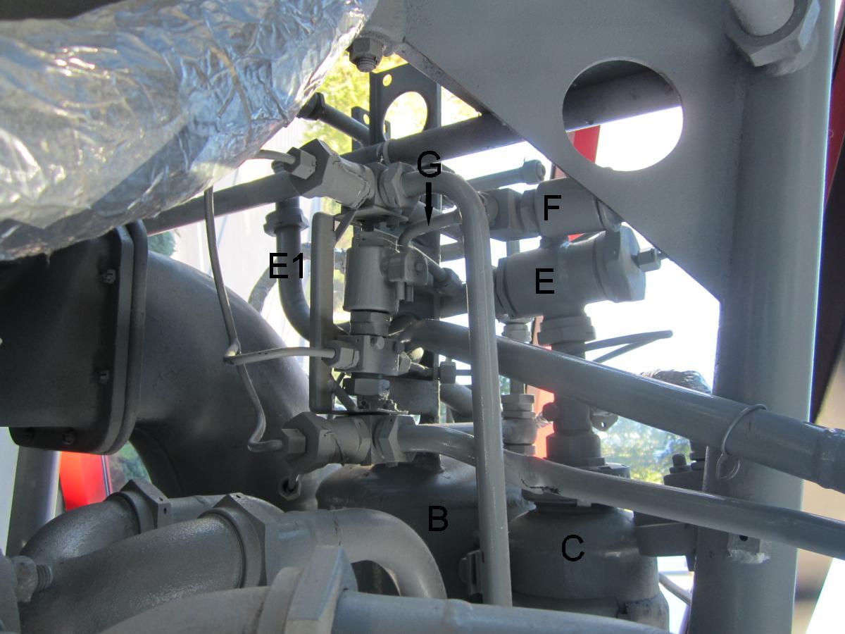 |
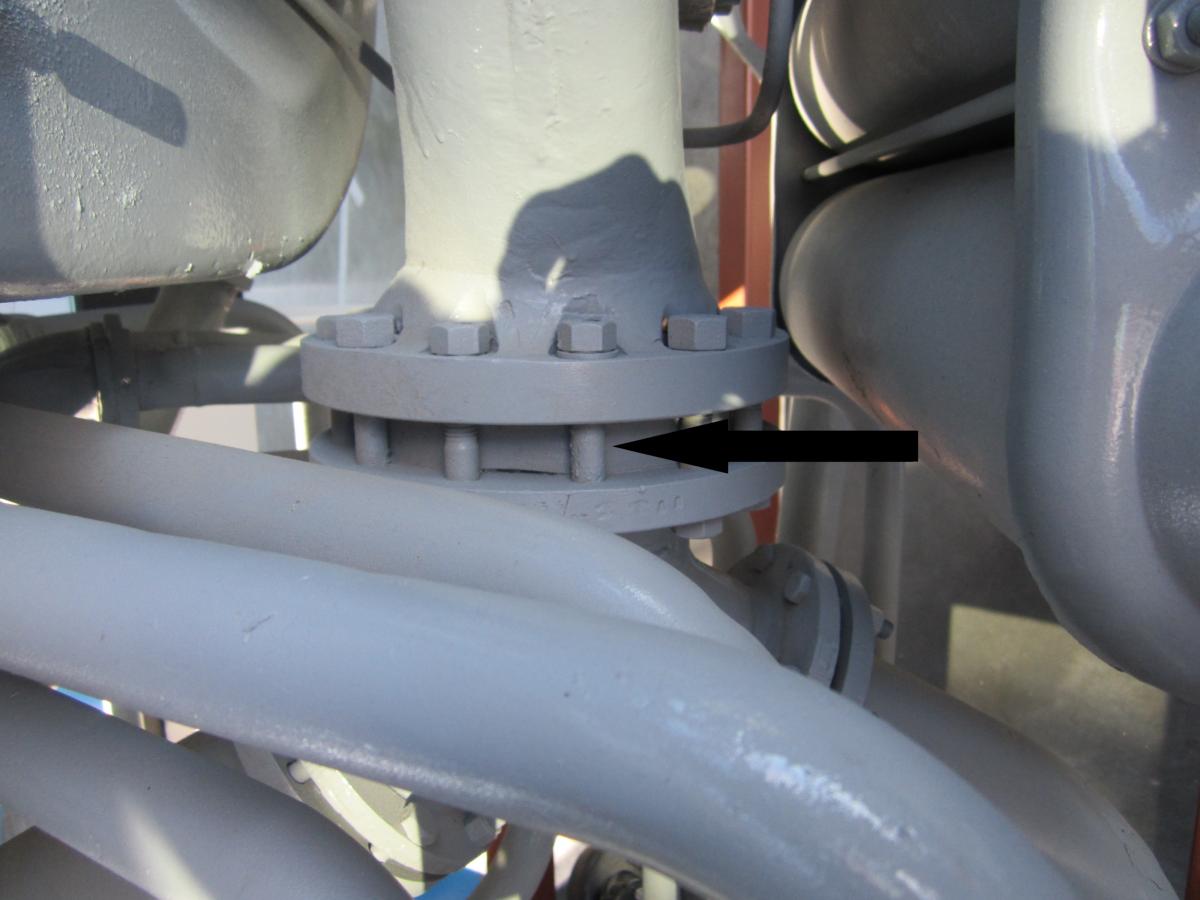
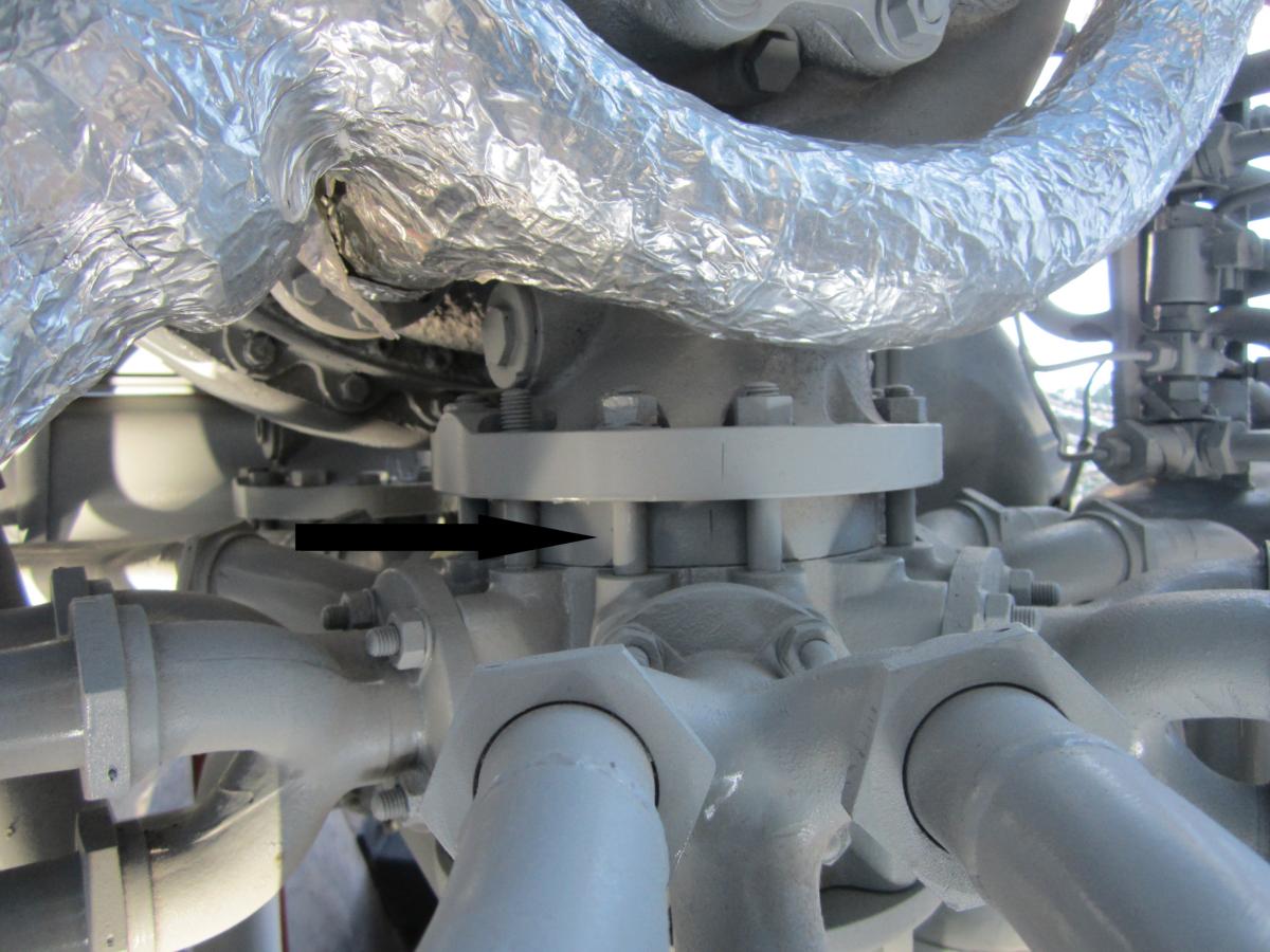
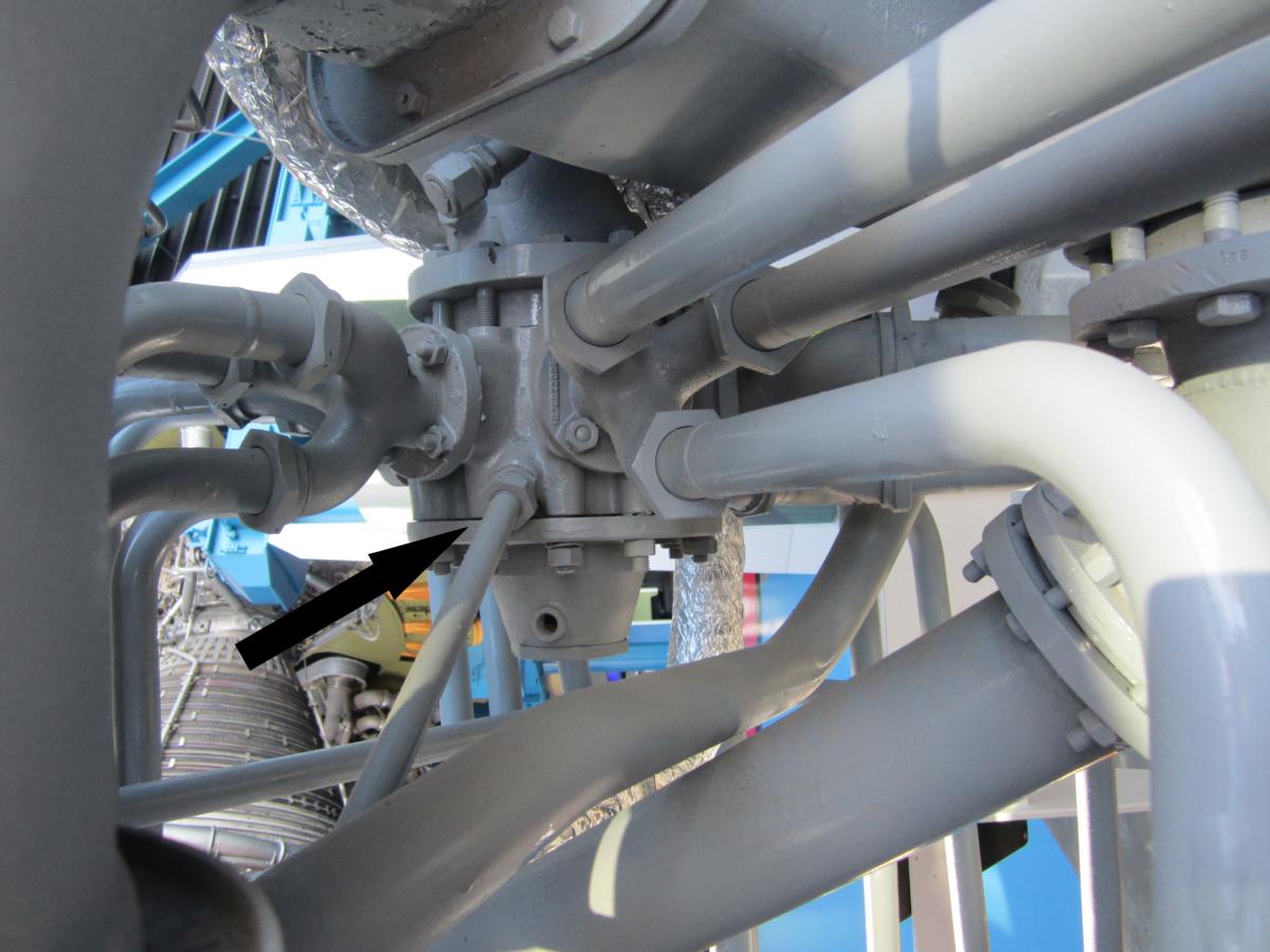
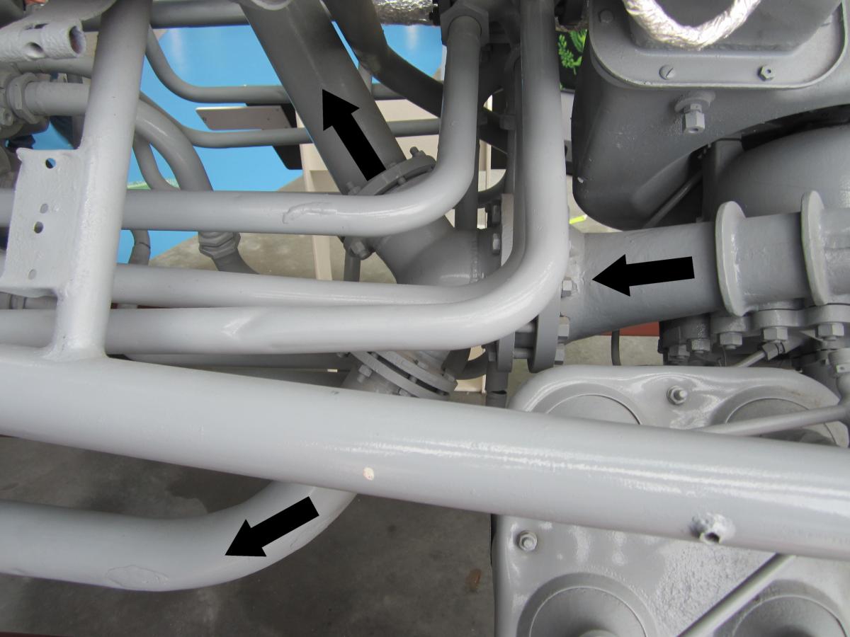
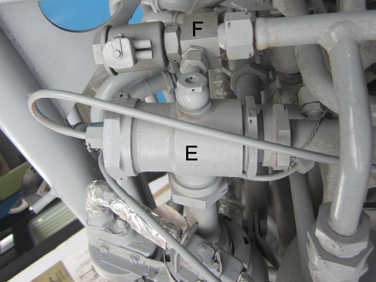
| V-2 Steam Plant Overview. A = Peroxide Tank; B = Permanganate Tank; C = Steam Generator | B = Permanganate Tank; C = Steam Generator; D = Permanganate Pressure Switch; E = 25-Ton Valve | The 25-ton valve (E) allows peroxide to pass unrestricted from the 8-ton valve port (E3) to the steam generator port (E2). When the actuation pistion is pressurized via E4, a poppet valve allows peroxide to also pass from the supply port (E1) to the steam genarator port (E2). | The 8-ton valve (F) lies slightly above and inboard of the 25-ton valve (E). | Steam Plant from the Inside. B = Permanganate Tank; C = Steam Generator; E = 25-Ton Valve; F = 8-Ton Valve; G = Tube Connecting Peroxide Input Line (E1) to the 8-Ton Valve (F). |
Control and Sequencing
Launch
Start
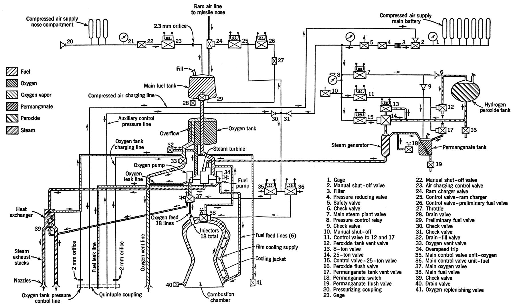 |
| V-2 System Schematic |
Main Stage
Flight
Cut-Off
| Engine | Model 39 |
|---|---|
| Used In | German V-2 |
| Era | 1943 |
| Thrust,SL (lb) | 55,000 |
| Thrust, Vac (lb) | ? |
| Burn Time (sec) | 60 |
| Chamber Pressure (psi) | 218 – 239 |
| Specific Impulse (sec) | 203 – 239 |
| Propellant Flow (gps) | 33.5 |
| Propellant Flow (lb/sec) | 286 |
| Nozzle Expansion Ratio | 2.83 |
| Engine Weight (lb) | 2,484 |
| Thrust / Weight | 22 |
| Fuel | 75% Ethanol 25% water |
| Oxidizer | LOX |
| Mixture Ratio (Ox/Fuel) | 1.13 |
| Turbopump Output (hp) | 580 |
| Turbine RPM | 3,800 |
Sources
Hunley, J.D. Technology for U.S. Space-Launch Vehicles, 1926 – 1991 (College Station, Texas: Texas A&M University Press, 2007)
Mueller, F.K. A History of Inertial Guidance (Redstone Arsenal, Alabama: Army Ballistic Missile Agency, 1963)
Neufeld, Michael J. von Braun: Dreamer of Space, Engineer of War (New York, New York: Random House, 2007)
Schulze, H.A. Technical Data on the Development of the A4 V-2 (Huntsville, Alabama: Historical Office, Marshall Space Flight Center, Feb 1965)
Sutton, George P. Rocket Propulsion Elements (New York, New York: John Wiley & Sons, 1949)
Robert J. Dalby, FRAS, A4 / V-2 Historian and Lecturer, has created an excellent website and several videos about the V-2:
Building the V-2 Rocket Engine
Hunting the ghost of the V2 in the Rocketdyne A-7
A4 / V2 Rocket in detail: Turbopump Part 1
A4 / V2 Rocket in detail: Turbopump Part 2
A4 / V2 Rocket in detail: A72 launch switch
A4 / V2 rocket in detail: Bringing a V2 rocket gyro back to life
A4 / V2 Rocket in detail: umbilical cable system
--- On To Part 3 ---
Send mail to
![]() with questions or comments about this web site.
with questions or comments about this web site.
![]()