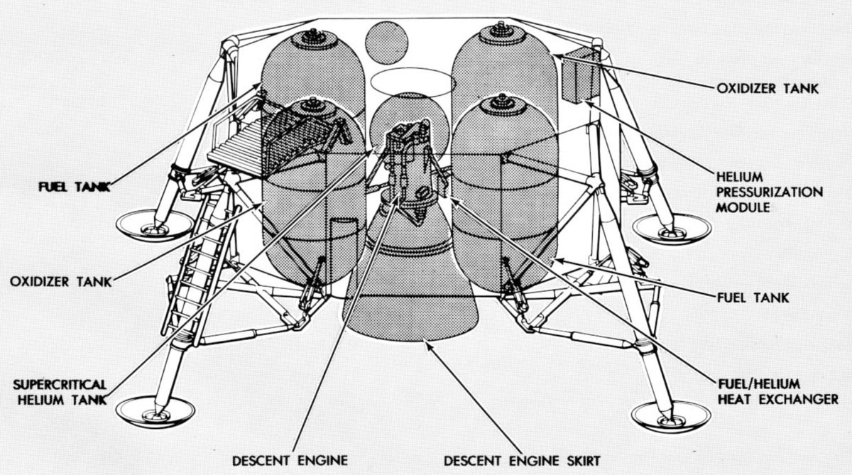
DPS Component Location
U.S. Manned Rocket Propulsion Evolution
Part 9.41: Lunar Module Descent Propulsion System (DPS)
Compiled by Kimble D. McCutcheon
Published 28 Dec 2021; Revised 4 Aug 2022
DPS Component Location |
The DPS was designed to transfer the fully crewed and loaded lunar module from lunar parking orbit to the lunar surface and to hover above the lunar surface for exact landing-site selection. This feat required a propulsion system that used hypergolic propellants and a gimbaled, pressure-fed, ablatively-cooled, ~10,000 lbT engine capable of being throttled. A lightweight cryogenic helium pressurization system also was used. DPS design and development covered approximately 7 years from conception to the first manned lunar-landing, Apollo 11. |
Introduction
|
The DPS provided the necessary velocity change (ΔV) to transfer the LM from lunar orbit to descent orbit and for powered descent to a lunar landing. The DPS was initially intended to support a 26,000 lb LM weight and a ΔV of about 6,000 fps. Later, as the LM was better defined, its weight increased to over a 36,000 lb and impulse required to a 7,000-fps ΔV for landing. This all had to be accomplished after the DPS had been in standby from launch through translunar coast and lunar-orbit coast (about 100 hrs). When the DPS was awakened it executed a burn to accomplish a Hohmann transfer from a 60-nautical-mile circular lunar orbit to a 60-nautical-mile by 50,000-foot elliptical descent orbit, and a powered-descent burn from 50,000 feet to a lunar-surface landing. The powered-descent burn required engine throttling and thrust vectoring. The hover phase included the last 1,000 feet of descent to the lunar surface. Also, the DPS provided contingency mission-abort capability if the SPS became inoperative during translunar coast, lunar-orbit insertion, or early lunar-orbit coast. Because the mission was to be manned, very high system reliability was another design requirement. To achieve all these goals a DPS design featuring a pressure-fed storable-propellant propulsion system using an ablatively-cooled engine was selected.
The DPS operated in concert with the LM reaction control subsystem (RCS), whose propulsion enabled precise attitude and translation maneuvers. If the descent was aborted, either the ascent or descent engine could return to a rendezvous orbit with the CSM. The choice of engines depended on the abort cause, descent stage propellant remaining, and length of time the descent engine had been firing.
Operation And Control
After initial DPS pressurization, the descent engine start required distinct arming and firing operations. Astronauts manually performed engine arming, but firing could be done manually by the astronauts, or automatically by the LM guidance computer. When the descent engine was armed, power was simultaneously routed to open the descent engine actuator isolation valves, enable DPS instrumentation circuits, and start the descent engine at a 10% thrust level. The LM guidance computer and the abort guidance system received an engine-armed status signal, which enabled an automatic engine-run program in the CN&CS, resulting in a descent engine start. A manual start was accomplished when the LM Commander pushed his engine-start pushbutton. Either astronaut could stop the engine engine-stop pushbuttons provided at both crew stations. The low 10% thrust nominal start profile for all descent engine starts was used to permit corrective gimbaling if the thrust vector was not directed through the LM center of gravity.
The astronauts could select automatic or manual throttle control modes, LM Commander or LM Pilot thrust/translation controller authority, and could override automatic engine operation. Redundant circuits, under astronaut control, ensured descent engine operation if prime control circuits failed. Signals from the GN&CS automatically controlled descent engine gimbal trim a maximum of 6° from the center position in the Y- and Z-axes to compensate for center-of-gravity offsets during descent engine firing. This ensured that the thrust vector passed through the LM center of gravity. The astronauts could interrupt descent engine gimbaling if a caution light indicated the gimbal drive actuators were not following gimbal commands.
 |
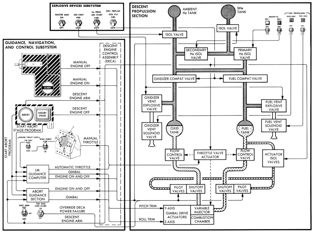 |
| DPS Flow Diagram | DPS Control Diagram |
Description
DPS propellants, Aerozine 50 fuel and nitrogen tetroxide oxidizer, had a relatively high specific impulse (305 sec), were storable for long periods, hypergolically ignited for easy, closely-spaced engine starts, insensitive to shock, had reasonable freezing and boiling points, and were chemically stable. Before starting the engine under weightless conditions, propellants had to be settled to the tank bottoms with an ullage maneuver using RCS downward-firing thrusters. Ullage is the void space required to accommodate thermal expansion of stored fluids. The DPS consisted of pressurization subsystem, a propellant feed subsystem, and a rocket engine that could be shut down and restarted as required.
Pressurization Subsystem
Before launch, all LM propellant tanks were partly pressurized to < 230 psia so that they would maintain safe pressure levels under the temperature changes expected during launch and earth orbit. Before initial engine start, the ullage space in each propellant tank required additional pressurization, which used a small amount of helium stored at ambient temperature and at an intermediate pressure. To open the path from the ambient helium tank to the propellant tanks, the astronauts fired an ambient helium isolation valve and two propellant compatibility valves that prevented propellant vapor backflow from degrading upstream components. After flowing through a filter, the ambient helium entered a pressure regulator that reduced its pressure to about 245 psi. The regulated helium then flowed via parallel paths through quadruple check valves into the propellant tanks. The quadruple check valves, consisting of four valves in a redundant series-parallel arrangement, permitted flow in one direction only, thus protecting upstream components against corrosive propellant vapors and preventing hypergolic ignition.
After initial ambient-helium pressurization, supercritical (a high pressure state with properties of both a liquid and a gas) helium was used to pressurize the propellants. The supercritical helium tank was isolated by an explosive valve, which was automatically opened 1.3 sec after descent engine start. The time delay prevented the supercritical helium from entering the fuel/helium heat exchanger until propellant flow was established so that the fuel did not freeze in the heat exchanger. Once the explosive valve opened, supercritical helium entered a two-pass fuel/helium heat exchanger where the fuel slightly warmed it. Helium then flowed back into a heat exchanger in the supercritical helium tank where it increased the supercritical helium's temperature, causing a pressure rise and ensuring continuous helium expulsion as long as the DPS operated. Finally, the helium flowed through a second fuel/helium heat exchanger loop where it was heated to operational temperature before being regulated and routed to the propellant tanks.
Supercritical helium was stored at a density approximately eight times that of ambient helium. Because heat transfer through the cryogenic storage vessel caused a gradual increase in pressure (approximately 10 psi per hour), the initial loading pressure was planned so that the supercritical helium would be maintained within a safe pressure/time envelope throughout the mission. The double-walled supercritical helium tank consisted of an inner spherical tank and an outer jacket. The void between the tank and jacket was filled with aluminized Mylar insulation and evacuated to minimize ambient heat transfer into the tank. The vessel had fill and vent ports, a burst disk assembly, and an internal helium/helium heat exchanger. The inner tank was initially vented and loaded with cryogenic liquid helium at approximately 8°R (-452° F) at a pressure of 14.7 psia. The cryogenic liquid became supercritical helium when the fill sequence was completed by closing the vent and introducing a high-pressure head of gaseous helium. As the high-pressure, low-temperature gas was introduced the cryogenic liquid helium density and pressure were increased. At the end of pressurization the stored supercritical helium density was about 8.7 lb/ft³.
A burst disk assembly prevented hazardous helium pressure vessel overpressurization. It consisted of two burst disks in series, with a normally open, low-pressure vent valve between the disks. The identical burst disks burst at a pressure between 1,881 and 1,967 psi to vent the entire supercritical helium supply overboard. A thrust neutralizer at the downstream burst disk outlet diverted the escaping gas into opposite directions to prevent unidirectional thrust generation. The vent valve prevented low-pressure buildup between the burst disks if the upstream burst disk leaks slightly. The valve opened at pressures below 150 psia and closed when the pressure exceeded 159 psia.
The helium pressure reduction scheme consisted of two parallel, redundant regulators. If one pressure regulator failed astronauts closed the malfunctioning line and opened the redundant line, restoring normal propellant tank pressurization. A relief valve protected each propellant tank against overpressurization by opening at about 260 psia and reseating after overpressurization was relieved. A thrust neutralizer prevented the vented gas from generating unidirectional thrust. Each relief valve was paralleled by two series-connected vent valves, which were operated by CM panel switches. After landing the astronauts relieved pressure buildup in the tanks caused by rising temperatures thereby preventing uncontrolled venting via the relief valves. The fuel and oxidizer fumes were vented separately and supercritical helium was vented at the same time.
Propellant Feed Subsystem
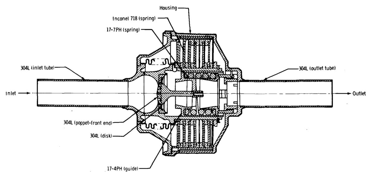
The DPS propellant supply was contained in four cylindrical, hemispherical-ended titanium tanks of identical construction that were initially built by the General Motors Allison Division of Indianapolis, Indiana, and later built by Sargent Industries Airite Division of El Segundo, California. Two equally-sized tanks contained fuel and the other two equally-sized tanks contained oxidizer. Each tank pair was interconnected at the top and all downstream propellant lines contained trim orifices that balanced propellant flow. A helium inlet port diffuser at each tank's top distributed pressurizing helium uniformly into the tank. An anti-vortex device at each tank outlet prevented propellant swirling, thereby precluding inadvertent engine helium ingestion. Each tank outlet also had a propellant retention device (aka, negative-g can) that permitted unrestricted propellant flow from the tank under normal pressurization, but blocked reverse propellant flow under zero-g or negative-g conditions. This arrangement ensured helium did not enter the propellant outlet line as a result of a negative-g or zero-g condition or propellant vortexing thereby eliminating engine helium ingestion.
Propellant Quantity Gaging System
A propellant quantity gauging system (PQGS) enabled astronauts to monitor propellants remaining quantities in the four DPS tanks. The PQGS consisted of four quantity-sensing probes with low-level sensors (one for each tank), a control unit, two quantity indicators that displayed remaining fuel and oxidizer quantities, a switch that allowing astronauts to select a fuel/oxidizer tank set to be monitored, and a descent propellant quantity low-level warning light, which indicated the propellant level in any tank was down to 9.4" (equivalent to 5.6% propellant remaining. When this warning light illuminated the propellant remaining quantity was sufficient for only 2 minutes of engine burn at hover thrust (approximately 25%).
Engine Assembly
The TRW Lunar Module Descent Engine (LMDE) was mounted in the descent stage center compartment cruciform. Fuel and oxidizer entering the engine assembly were routed through flow control valves to the propellant shutoff valves. A total of eight propellant shutoff valves were arranged in redundant series-parallel scheme, four in the fuel line and four in the oxidizer line. The series redundancy ensured engine shutoff if one valve failed to close. The parallel redundancy ensured engine start if one valve failed to open. Oxidizer reached the injector first to prevent rough engine starts. The propellants were then injected into the combustion chamber, where hypergolic ignition occurred.
DPS Development
From the initial 1963 DPS design, system reliability, weight, and component design considerations resulted in numerous changes, many of which are described below.
Pressurization Subsystem
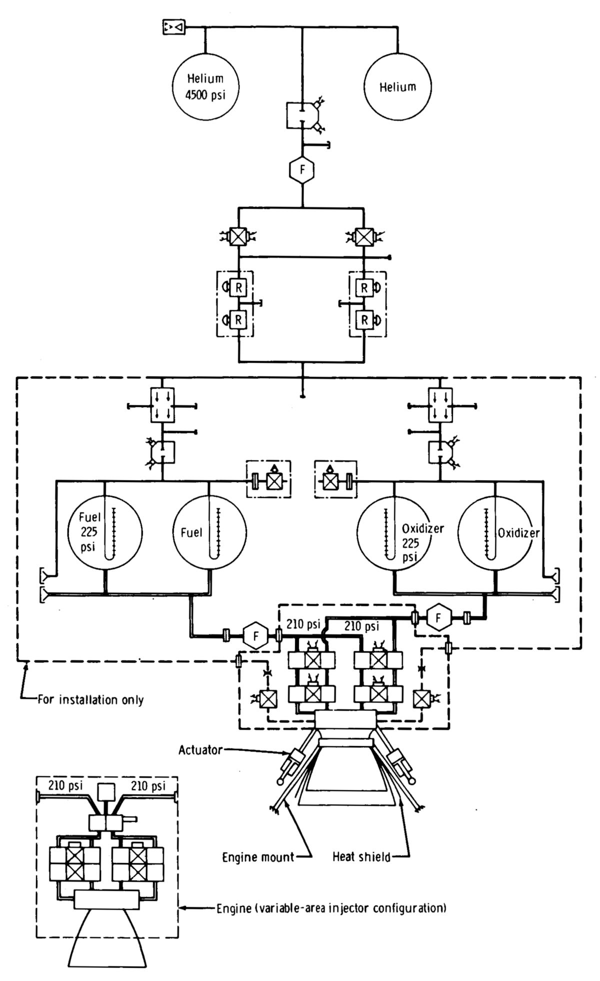 |
| Initial DPS Design |
The initial DPS pressurization concept used helium stored at 4,500 psia two high-pressure tanks; this was later was changed to 3,500 psia to reduce subsystem weight. As the LM design progressed, vehicle weight became a critical factor and gave rise to an early 1964 investigation into using supercritical helium (SHe) pressurization subsystem storage. The idea was to store very dense helium at approximately 10°R in a highly thermally insulated pressure vessel. Pressure in the storage tank was allowed to rise because of the heat leak into the tank (approximately 8 to 10 Btu/hr). As helium was used from the tank, additional heat would be provided to the helium in the tank to raise further the pressure by the use of an external fuel-to-helium heat exchanger and an internal helium-to-helium heat exchanger within the tank through which the total helium flow passed. Subsequently, the helium was routed through a second pass in the fuel-to-helium heat exchanger to raise the helium temperature to nearly ambient conditions (approximately 40° F) before it was supplied to the pressurization subsystem pressure regulators.
By late 1964, SHe subsystem analysis and feasibility testing indicated that it was operationally feasible and that a weight savings of 280 pounds could be realized by using the SHe subsystem rather than the ambient-storage subsystem . In February 1965, NASA and Grumman decided to redesign the DPS pressurization subsystem to incorporate an SHe storage tank. Because pressure in the SHe storage tank increased with time, a minimum-required standby time was defined as 131.5 hours from prelaunch top-off until first usage in the nominal lunar landing.
Developmental problems and reliability requirements reassessment sparked an Oct 1966 decision to use only parallel redundancy in the pressure regulation subsystem (single regulators in each leg). Engineers rationalized that if a wide-open regulator failure occurred, the propellant tanks would be protected from over pressurization by relief valves, and the crew, using the latching solenoid valve, could eventually isolate the failed regulator. This factor would save the subsystem, and the mission could be continued on the second regulator or could be aborted with the ascent propulsion system. To achieve required engine performance, another design change was made to increase the regulated pressure level from 210 psia to 246 psia.
During design and development of the SHe pressurization subsystem, fuel freezing in the fuel-to-helium heat exchanger occurred during the start sequence under certain start conditions. The freezing was caused by the substantial helium flow needed to bring the propellant tanks from prepressurization levels to regulator lockup pressure, during which time no fuel was flowing through the heat exchanger fuel passages. A study to alleviate cold helium flowing with no fuel flow led to the use of an ambient-helium prepressurization start bottle, which was simple and reliable.
Propellant Storage and Feed Subsystem
 |
 |
| Initial Design | Final Design |
The DPS used two oxidizer and two fuel tanks for optimum center of gravity (cg) and weight control. The identical propellant tanks were fed in parallel to minimize cg excursion during propellant usage. Balance lines at the tank tops and bottoms ensured balanced propellant flow from each tank. A burst-disk assembly and relief-valve assembly in the pressurization line leading to each tank pair provided overpressue protection. The burst-disk assembly in series with the relief-valve assembly provided a positive leakage seal until the pressure relief subsystem was needed. The initial burst disk and relief valve design was an integral assembly incorporating a frangible disk and cutter arrangement. Because the burst pressure for this design was not repeatable, the maximum tank pressure was 308 psia. The burst-pressure rating of this design disk was 288 + 20 psia, which was based on lot-sample testing and qualification testing. The 1.3 propellant tank safety margin was limited severely with this design. Also, the fracture-flaw growth potential caused by pressure cycling (fracture mechanics) was more critical than normal, thereby limiting the allowable pressure cycles on the tanks during checkout, servicing, and flight. A new burst disk with a 267.5 ± 7.5 psia burst-pressure improved the propellant tank safety margins and pressure-cycling limitations. The new burst disk could also withstand reverse-pressure differentials of about 150 psid without damage, which eliminated the many checkout failures with old burst disk resulting from inadvertent reverse pressure.
DPS operation during a lunar mission could have resulted in heat soakback from the engine after lunar landing, which could cause the propellant tanks surrounding the engine compartment to warm, raising their pressure, and causing the burst-disk and relief-valve to open. If this venting occurred during extravehicular activity on the lunar surface, astronauts could have been sprayed with propellant vapors. A propellant-tank lunar-dump subsystem consisting of an explosive valve and latching solenoid valve in series was added to a bypass line around the burst-disk and relief-valve assemblies. Actuation of the explosive valve and latching solenoid valves was controlled from the LM crew station.
A propellant-quantity gaging probe in each propellant tank provided continuous monitoring from 0% to 95% percent of tank capacity. Integral to the propellant-quantity probes was a propellant low-level detector that warned the crew impending propellant depletion as the propellant quantity reached a discrete value of 5.6% in any tank.
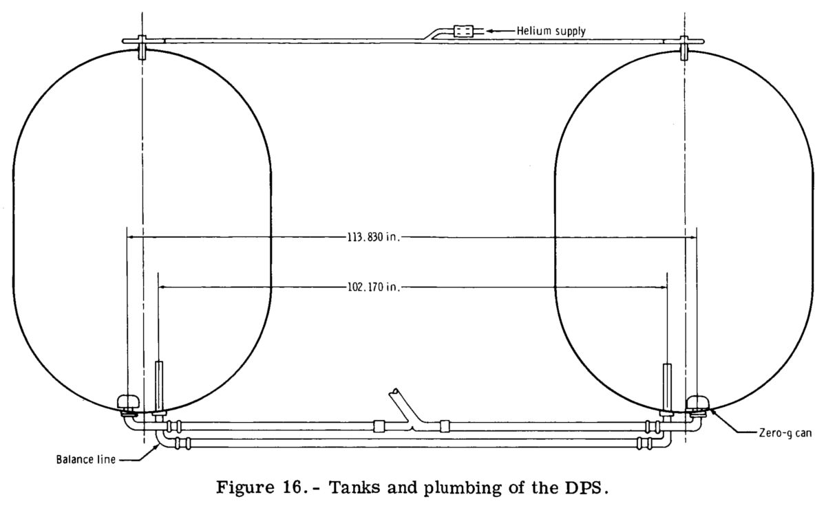 |
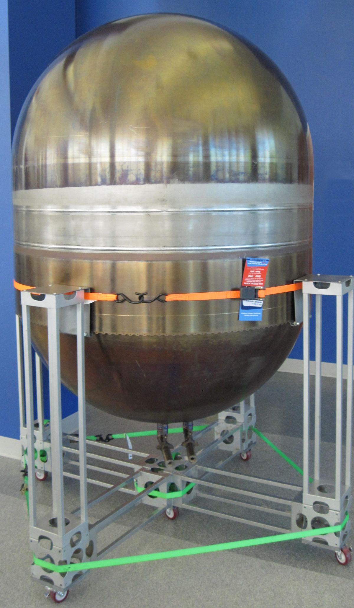 |
| Tanks and Plumbing | Propellant Tank |
Development and Qualification Issues
DPS development and qualification, including component- and system-level work, lasted from August 1963 until April 1969. In many cases, preproduction component configuration were used in early system level developmental testing. In the developmental and qualification testing of components and systems, extensive design-limit tests, off-limit tests, and malfunction tests were used to determine potential design deficiencies and to document operational system limits.
SHe subsystem developmental tests on an early design feasibility test rig identified unique SHe tank-loading requirements and resulted in a parallel GSE SHe servicing subsystem development. SHe flight tank development began in May 1965, with the tanks being manufactured by The Garrett Corporation's Airesearch Manufaturing Company of Los Angeles, California. A preproduction tank with an unsupported coil-type internal heat exchanger was very sensitive to the simulated flight vibration and experienced resonance and vibration amplification at certain frequencies. Its thermal performance was affected by large pressure oscillations as oscillating pressure waves passed through the internal heat exchanger. This problem was corrected by a small line interconnecting the heat-exchanger inlet and outlet lines just outside the tank, thus damping the oscillations, but the fix introduced a path that permitted continuous circulation through the internal heat exchanger and subsequent tank thermal performance degradation. Developmental tests on preproduction tanks at the NASA White Sands Test Facility (WSTF) proved that this circulation phenomenon was a function of the vertical heat-exchanger orientation and the associated head difference between inlet and outlet lines . As a result of circulation, pressure-rise rates as high as 200 psi/hr were detected. In the production tank, the internal heat exchanger was reconfigured to a fully supported (from inner-vessel wall) coil in the lower half of the tank with the inlet- and outlet-tube penetrations going through the bottom of the inner vessel. The interconnecting line was still required to prevent heat-exchanger circuit pressure oscillation.
In the first production-tanks the copper vacuum annulus pinch-off tube had an excessive pressure rating that would rupture the outer shell if a gross inner vessel helium leak occurred. The tube was redesigned and tested to provide a lower relieving pressure within outer-shell limits, and all production tanks were retrofitted or fitted with the new pinch-off tube. During handling and acceptance tests, the outer shell collapsed locally several times. The most prevalent local collapse location was around the outer shell heat-exchanger tube penetration. No definite conclusions were reached concerning the collapse cause other that some tanks were marginal in outer-shell strength. As a result of the collapse, the external pressure-proof test on the outer shell during acceptance testing was reduced from 19.5 psia to 18.5 psia. However, this reduced pressure did not completely eliminate collapse. Collapsed tanks were refurbished by installing new outer shells.
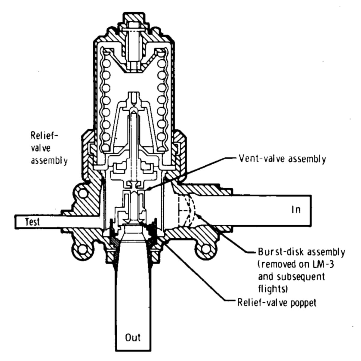
 |
| SHe Tank Burst Disk |
The SHe tank dual burst-disk assembly was designed with stainless-steel Belleville (conical compression) washer springs (17-7 PH) that controlled the burst disk burst-pressure setting. During certain vehicle checks on an SHe tank, the primary disk ruptured at approximately 300 psi below the set pressure of 1,881 to 1,967 psia, This rupture was traced to Belleville spring stress corrosion caused by long-term moisture exposure. One spring of the four-spring stack was cracked completely through; thus, the burst disk preload was lowered. If moisture was detected by a vacuum-dryness check, a pressure-proof test was performed on all production burst disks. Also, desiccant bags were maintained on the outlet tube of all burst disks after the dryness check and the pressure-proof test. Subsequent to LM-5 (Apollo 11), some vehicles' the burst disk were modified to incorporate an Inconel Belleville spring, which was resistant to stress corrosion.
The principal SHe GSE items developed for servicing the SHe subsystem were an SHe conditioning unit and a liquid-helium dewar. Among the design requirements of this equipment were that the automatic checkout equipment (ACE) could remotely control and monitor the equipment and that the equipment could meet the size and weight limitations required for placement close to the LM SHe tank (on the launch-pad mobile-service structure). These two requirements were significant constraints in the development of this equipment.
The liquid-helium dewar initial design inner vessel structural support was marginal. During trucking of one dewar with a full load of liquid helium, the inner vessel vibrated so badly that the fill and discharge tube at the tank bottom were cracked and released liquid helium into the annulus, thus imploding the inner vessel, releasing the expanded helium because the outer vessel relief was not adequate. Subsequently, the dewar was modified to increase the bumper pad stiffness and to improve the suspension-cable annulus arrangement.
The fuel-to-helium heat exchanger development began in June 1965. Primary goals were high thermal performance, high reliability, and good structural integrity. The initial heat exchanger configuration used a nickel-chromium braze alloy to bond the side panels and core. During lunar test article number five (LTA-5) at WSTF testing a side panels separated from the core and ruptured, which resulted in a gross fuel leak and fire. This failure was traced to the test rig factory test, in which the heat exchanger had been exposed to cryogenic temperatures with water in the fuel passages. The water froze, breaking the nickel-chromium braze material. Subsequent WSTF exposure to system-operating pressure resulted in side panel rupture. To avoid this problem on subsequent vehicles, the nickel-chromium braze was changed to a gold-alloy braze, increasing the side panel bonding strength, and water was eliminated from cold flow testing when cryogenic helium was used.
In the initial latching solenoid valve design, nylon and Butyl O-rings were considered adequate for a 3.5-day exposure to propellant vapor. By mid-1966, tests had proved that backup rings and lubricants were necessary to prevent severe Butyl O-ring chewing during cycling. Parallel compatibility tests proved the nylon seat was inadequate. Late in April 1966, the seat was changed to the present Teflon material. Teflon backup rings were also replaced with Teflon cap seals and electromagnetic interference suppressors were added. In November 1967, the latching solenoid valve, installed in a prototype descent stage number two (PD-2) at WSTF, failed to remain in the latched-open position after a rapid open-close command. The problem resulted because of residual magnetism in the latch plunger that exceeded the spring-return force when the valve was cycled rapidly. A high-rate latch spring, modified latch plunger (to house the new spring), and shims to maintain the required latch-spring force were added to each valve assembly. Two valves were successfully subjected to qualification tests that were completed in Spring 1968. In March 1968, the latching solenoid valve on LM-3 leaked externally through the valve body-to-tube nickel-chromium brazed joint. The solenoid valve was redesigned for LM-5 and subsequent vehicles with a brazed joint that had the proper clearances and that used gold-nickel alloy as the braze material. To certify the solenoid valves for LM-3 and LM-4, a special test program was successfully completed with the nickel-braze configuration. Because the valves were not to be flown on lunar landing missions, a program decision was made to accept the potential occurrence of a leakage failure on LM-3 and LM-4. A delta qualification test program (recertification of certified part) was conducted to certify the gold-braze configuration for flight.
The helium pressure regulator development started in June 1964 and was troubled by many problems, especially internal and external leakage. The regulator failed to meet the slam-start requirements (lockup with high pressure upstream and initially with vacuum downstream coupled with minimum downstream volume). Cracking of the main poppet and high lockup pressure were the two major problems during slam starts. Hardware scarcity restrained the developmental program.
In October 1966, an alternate pressure regulator vendor was selected and in mid-1967, the original vendor was terminated. The new regulator exhibited a pressure-spiking characteristic during slam starts although it locked within the maximum limit of 251 psia. The spike was as high as 266 psia in the vicinity of the burst disk and relief valve. No corrective action was made to the regulator; however, this phenomenon was specified as a design requirement for the burst disk.
Two contamination incidents in the reference sensor port resulted in high lockup pressures. One incident of wide-open failure on the primary stage was caused by contamination in the pilot poppet seat. The failures resulted from inadequate contamination control. Special precautions were implemented to prevent their occurrence on flight hardware.
The quad-check-valve design was used in the ascent propulsion system and DPS. Conducted on two valves, the qualification test program was completed successfully in November 1966. Some of the valves did not meet the initial specification of 10 scc/hr (scc = standard cubic centimeter, a gas leakage metric); however, the actual leakage rates were acceptable for the LM missions. The maximum-allowable leakage was increased to 100 scc/hr for each element and to 100 scc/hr for the overall valve. Excessive leakage later occurred on several flight vehicles, In August 1968, failure analysis conducted on internally leaking check valves indicated that most of the internal leakage problems experienced on the LM vehicles were caused by seat contamination. Investigation of these failures led to assembly modification, installation, and cleaning procedures at the facility of the vehicle contractor and at the facility of the component vendor.
The propellant storage and feed subsystem development and qualification was conducted on a component and a system-level basis. Early evaluation tests were conducted on the feedline and parallel-tank balance-line configuration by use of a heavyweight test rig. The major objectives of these tests were to determine the effectiveness of the propellant utilization and the propellant management control under system operating flow conditions. The major concern was evidenced at maximum thrust because differences in system pressures would cause maximum propellant unbalance. At reduced thrust, the engine-cavitating venturis provided the major propellant-utilization control. No major problems were discovered during these tests.
Considerable propellant storage tank weld porosity early in the Apollo program dictated some rewelding; however, as experience was gained, porosity was gradually reduced by adjusting weld speed and current values. During the proof-pressure test of tank S/N P-009 (8 Mar 1965), rupture occurred at 267 psi; the required proof pressure was 360 psi. The premature failure was traced to a massive alpha inclusion a low-density, hard, brittle region of spuriously high nitrogen and oxygen content) in the upper dome near the helium inlet boss. The inclusion source was not determined; however, the vendor speculated that it probably occurred during smelting operations when a small piece of oxidized titanium dropped off the vat side into the slurry during solidification. The metals company was advised of this so that the possibility of recurrence was minimized.
During helium-leakage testing of tank S/N G-029 (August 23, 1966), rupture occurred at a pressure of 180 psi. This rupture happened after the tank had been proof tested. Failure was traced to stress corrosion in the access covers. Early in the Apollo Program, the access covers were made of 6Al-4V titanium alloy. However, a careful analysis indicated that weight could be saved by changing the material to aluminum alloy because of the large amount of low-stress material in the bosses. Previously, these access covers had been proof tested with uninhibited tap water as the fluid. The stress corrosion that caused the tank failure probably occurred during the uninhibited water proof test because the 2014-T651 aluminum alloy was susceptible to stress corrosion under these conditions. Therefore, the decision was made to return to the use of titanium-alloy access covers.
Numerous cracks were found in the contractor-furnished tank support skirt and deck. These cracks appeared after X-X axis vibration tests. Cracks also occurred in the plumbing support brackets and baffles. Deficiencies were corrected by increasing the material thickness and elimination of stress risers.
Early tank/access cover seals were butyl rubber SR 634-70. However, this material tended to deteriorate above 90° F after exposure to nitrogen tetroxide. The seals were replaced with a different design composed of a V-shaped Teflon coated stainless-steel ring.
A weight-reduction program involved changing the stub support skirt, the cover attachment flanges and to the cover itself. The stub skirt was shortened and the spaces between the rivet holes were scalloped to remove useless material. The elimination of a seal, which caused considerable difficulty in subsequent helium-leak checks, allowed material to be removed from the tank and cover flanges.
Stress corrosion from nitrogen tetroxide was a major problem. Several solutions were considered, including a Teflon wall coating, shot peening the wall surfaces, changing the tank material, and changing the oxidizer specification. The nitrogen oxide content in the nitrogen tetroxide was increased to inhibit the stress corrosion.
Propellant quantity gaging system (PQGS) development began in January 1966. The initial continuous-quantity probe calibration accuracy requirement was ±0.25% throughout the full range. Because of the internal wiring configuration, standoffs, etc. in the space between the inner and outer electrode, this accuracy requirement could not be met and was changed. Low-level sensor accuracy was not affected. The revised accuracies were presented in the following table.
During PQGS probe vibration qualification tests (Y axis) the outer electrode cracked adjacent to a rivet hole. Since the vibration qualification requirements were more severe than flight requirements, vibration levels were redefined to more realistic values. Subsequently, the PQGS probes passed the vibration qualification test. During tests at WSTF and on the flight vehicles, the fuel-quantity indicators exhibited an initially low value (90 ‑ 95% for full tanks) when the PQGS was first started. In approximately 15 minutes, the indications settled to the correct or nearly correct full. Engineers attributed the time lag to a fuel conductivity gradient caused by trace amounts of contaminants, which were dispersed by heat from the sensor electronics at the probe bottom.
Leakage at the flange-to-tank access cover joint seal on LM-1 was attributed to inadequate flange flatness when the attaching bolts were torqued, unevenly compressing the single Teflon O-ring. A 0.375" stainless-steel backup ring was added to the flange to improve its torqued flatness. A secondary groove was also cut in the access cover flange into which a viscous sealant (Nitroso for the oxidizer and Vistanex for the fuel) was injected before bolt-torquing to provide a backup seal.
Testing
At WSTF a comprehensive ground-test program helped develop and certify the DPS for lunar landing. This test program spanned 3-1/2 years, from early 1966 and until mid-1969. Three propulsion test rigs were used.
Descent Propulsion Developmental Vehicle
The PD-2 propulsion rig was used for high-altitude firings. The PD-2 employed a flight weight primary structure and a secondary structure designed for small titanium propellant tanks and prototype propellant components. Tests performed on the PD-2 included substitute- and live-propellant cold-flow tests, off-nominal start and operating characteristics, component malfunctions, vehicle mission-duty cycle firings, and 500-Hz oxidizer-manifold oscillations.
Lunar Test Article 5 (LTA-5)
The LTA-5 was a full-scale LM descent stage with a complete production DPS. On 3 Jul 1967, following completion of the first system test (LM-1 mission-duty cycle (MDC)) and while still at altitude, the fuel-helium heat exchanger ruptured. During facility-securing operations, fuel that leaked from the heat exchanger was ignited by an unknown source. LTA-5 was extensively damaged in the subsequent fire. The LTA-5 was then refurbished to approximate the LM-3 and LM-4 configuration, and it was redesignated LTA-5D. Two tests, one in support of mission B (LM-1) and one in support of mission D (LM-3), were conducted before the start of mission-G testing.
Five MDC tests were accomplished to support the lunar-landing mission (mission G). The tests were performed to demonstrate the capability of the DPS to perform the mission-G MDC under nominal conditions, off-nominal conditions, and malfunction conditions. All tests were made with helium-saturated propellants. In addition to the MDC tests, one SPS abort-duty cycle was conducted with two long DPS burns and a long coast in between.
Flight Experience
LM-1 (Apollo 5)
The LM-1, the first flight LM, was launched on 22 Jan 1968 by a Saturn IB. The LM-1 was flown in an unmanned earth-orbital mission to evaluate subsystem flight performance and to verify man-rating. Two DPS anomalies occurred during the LM-1 flight. The engine shutdown prematurely during the first burn and a propellant shut-off valve (SOV) out-of-phase indication appeared during the second and third engine burns.
The first descent-propulsion maneuver, controlled by the primary guidance, navigation, and control system, was scheduled to last approximately 38 seconds. The descent-engine thrust monitor was programmed to stop the engine if any three consecutive 2-second-accelerometer samples indicated an accumulated velocity of less than 45 cm/sec. This criterion was based on a nominal engine start with the propellant tanks initially at full-operating pressure and with the helium supply on line. LM-1 did not have an ambient-start helium-storage tank, and the SHe tank was isolated by the three explosive valves that were fired automatically by the pyrotechnic system 1.3 ± 0.3 seconds after the first "engine on" command. Therefore, the system pressures during the first DPS start, which were normal for this particular system configuration, did not rise fast enough to meet the thrust-time criteria programmed into the guidance computer. All logic and circuits that could command any engine cutoff or inhibit any engine start were reevaluated to prevent unnecessary engine shutdown on subsequent flights. The thrust-monitor logic was the only circuit found to produce a premature engine shutdown.
During the transition from 10% throttle to full throttle on the second and third descent engine firings, an out-of-phase indication was received from one pair of the two-pair position switches that indicated the eight propellant shutoff valve positions. The out-of-phase indication remained until the end of both firings. Several causes were postulated including reed-switch failure (false indication), pilot-valve or actuator-hydraulic malfunction or leakage (valve failed fully or partially closed), and electrical-circuit failure (valve failed fully or partially closed). An investigation could not establish conclusively a single cause or combination of causes for the observed phasing anomaly. However, since the reed switches were known to be unreliable, the most likely cause was a false reed switch indication. The reed switches were eliminated from LM-5 and subsequent vehicles.
LM-3 (Apollo 9)
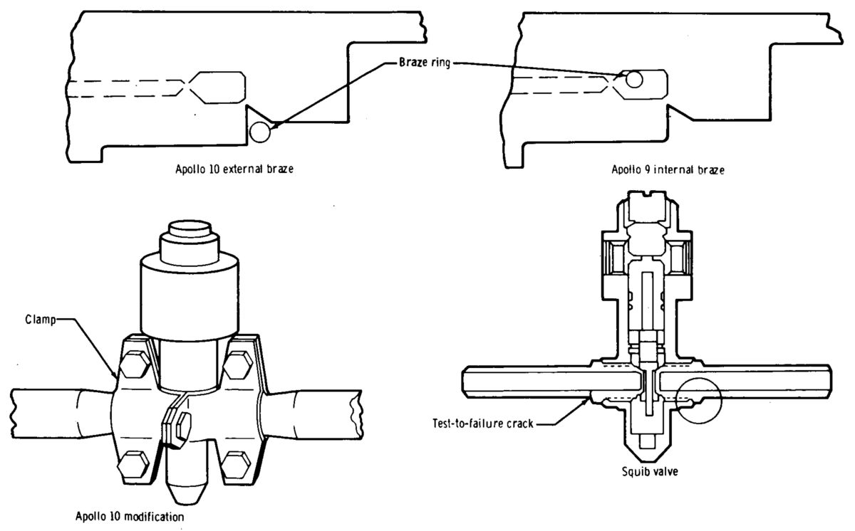 |
| SHe Squib Valve Configuration |
LM-3, the second LM to fly, was flown in a manned earth-orbital mission launched on 3 Mar 1969. The 10-day LM-3 mission was to qualify the LM for future flights and to demonstrate certain combined spacecraft functions for manned lunar flight. LM-3 incorporated the ambient-helium pressurization-start system to allow propellant tank pre-pressurization before the first burn. LM-3 also incorporated a lunar dump-valve venting system on each propellant tank set . The LM-3 guidance computer program was modified to prevent the inadvertent ΔV cutoff phenomenon experienced with LM-1.
Three LM-3 DPS flight anomalies occurred. The SHe tank internal-heat-exchanger froze during the first 35 seconds of the first descent-engine burn. The regulator outlet-manifold pressure dropped from 235 to 188 psia. The regulator should have regulated at 247 psia. Temperature data indicated that the internal heat exchanger was initially blocked. At approximately 35 seconds after engine ignition, the blockage cleared and allowed the regulator outlet-manifold pressure to rise to the proper operating level.
During final SHe tank servicing at the launch complex, the SHe tank had been topped-off and the helium heat-exchanger manifold vented to approximately 25 psia, an inadvertent venting of the helium heat-exchanger manifold to approximately atmospheric pressure occurred while the vehicle quick-disconnects were being warmed by a helium purge to allow their disconnection. During the quick-disconnect purge, the supply pressure probably was allowed to drop below atmospheric pressure, and outside air probably was cryopumped into the helium manifold by the cold heat exchanger in the SHe tank. Subsequently, the air condensed and froze in the internal heat exchanger near-liquid-helium temperature environment. The GSE was modified to isolate the purge system from the helium-manifold pressure-control system for subsequent flights. In addition, continuous pressure recording with proper scaling was employed.
DFS SHe tank pressure began decaying at the rate of 2.9 psi/hr immediately after the first descent-engine firing. The pressure decay continued until staging. Because of heat transfer into the tank, the pressure normally increased under no-flow conditions . Calculations showed that a leak of about 0.1 lb/hr would have caused the 2.9-psi/ hr pressure-decay rate. An internally brazed squib valve failure was found during drop tests of LM-2 at the NASA Manned Spacecraft Center. The failure was caused by a crack in the brazing material, which was thin in the failed area. The time of the failure could not be ascertained; however, it probably was caused by the shock of the squib firing to pressurize the ascent propulsion system. The LM-3 SHe squib valve was similar to the LM-2 squib valve in that the valve fittings were internally brazed, which prevented joint inspection. The LM-3 leak was probably caused by a defective internal squib valve braze that was and could not be inspected.
The mission criticality of external squib valve leakage was evaluated for each Apollo 10 squib valve. On the DPS, the oxidizer-compatibility squib valve was determined to be of the internal-braze configuration; thus, if external leakage developed, it could have been hazardous to the mission. Therefore, this valve was modified to incorporate RTV potting reinforced with an external clamp that contained any leakage if the brazes cracked. This configuration was thoroughly tested before the flight. The valves on all vehicles subsequent to Apollo 14 were of the external-braze configuration.
During the second descent-engine firing, rough combustion was encountered at approximately 27% thrust as the engine was being manually throttled from 12% to 40%. This roughness lasted for approximately 2.5 seconds, during which time the crew delayed increasing the throttle. Helium ingestion was the probable cause of the roughness. A possibility existed for helium bubbles to migrate into the propellant feedlines from the propellant tanks, which had 60% ullage volume after the first burn. This migration resulted from lateral and/or rotational vehicle acceleration combined with the fact that the zero-g-can retention screen was not capable of holding propellants at the 114-inch head between identical propellant tanks. Helium ingestion required that the zero-g can be uncovered and that lateral or rotational accelerations be present. This condition was highly probable with the 60% ullage volume present in Apollo 9 propellant tanks before the second descent engine firing. Tests demonstrated that helium ingestion the engine in this manner has no detrimental effect on the system.
LM-4 (Apollo 10)
LM-4, the third to fly and the second manned LM flight, was launched on 18 May 1969. The 8-day translunar and lunar-orbital mission was to confirm all lunar-landing mission aspects exactly as it would be performed, except for the actual descent, landing, lunar stay, and ascent.
During the phasing burn, the crew reported two master alarms caused by propellant-quantity low-level indications. The first was coincident with engine "on" command; the second immediately after throttling up to fixed throttle position. The crew reset the master alarm after the first low-level alarm, and the low-level indication was reported to have ceased working at that time. The low-level indication probably was caused by a gas bubble in the unsettled propellant uncovering the low-level sensor before the burn but after turning on the PQGS. Once the low-level sensor was uncovered, the indication was latched on by a latching relay and remained on until the PQGS was turned off again after completion of the burn. The crew display of low quantity was inhibited until the engine "on" command was given, thus explaining the master alarm at engine ignition. This fact was verified by the telemetry recording.
The second alarm could not be verified by telemetry nor explained by normal system operation. On subsequent missions, the low-level indication was removed from the master alarm because the low-level warning visual indication was considered adequate crew warning. Also, if the low-level indication occurred at engine ignition, a contingency crew procedure was instituted to reset the low-level indication by cycling the PQGS off and on.
LM-5 (Apollo 11)
LM-5, the first lunar-landing vehicle and fourth production LM to fly; its objective was a manned lunar landing and safe return to earth.
At landing, the quantity of propellants remaining in each of the four tanks was as follows: Oxidizer Tank 1 = 5.7%; Oxidizer Tank 2 = 2.7%; Fuel Tank 1 = 3.9%; Fuel Tank 2 = 3.9%. The minimum-usable quantities, based on the indication of oxidizer tank 2, allowed 63.5 sec hover time. Several minor anomalies occurred in flight. During the power-descent-initiation (PDI) burn, the oxidizer-engine-inlet pressures indicated low-frequency oscillations that varied from 24 psi peak-to-peak during the FTP operation to 67 psi peak-to-peak during throttle recovery (approximately 57%). The oscillations observed were characteristic of those observed in oxidizer-injector manifold and engine-inlet pressures in several ground-test engines, which were verified to be harmless to engine and system operation. During the PDI burn (hover phase) last 140 seconds, a series of large oscillating-throttle changes occurred. These changes were approximately 15% peak-to-peak about a nominal throttle setting of approximately 26%. Large and rapid changes in vehicle attitude (as much as 15° at 10°/sec) in pitch during the final landing phases caused centrifugal accelerations on the inertial-measurement-unit accelerometers located at the top of the ascent stage high above the vehicle cg, thereby giving a false indication of vertical acceleration. This false indication caused the lunar guidance computer to command a throttle change to compensate far an unreal change in vertical acceleration. Later, this problem was investigated under the analysis of the guidance and control system.
During the PDI burn, PQGS readings indicated the tank 1 and tank 2 oxidizer quantity diverged, until, at 360 seconds into the burn, oxidizer tank 2 was about 3.4% less than oxidizer tank 1. This divergence was attributed to propellant transfer from one oxidizer tank to the other through the propellant balance line. The vehicle cg offset from the centerline between the oxidizer tanks (on Z axis) resulted in tilting of the vehicle in that axis to put the thrust vector through the vehicle cg. This tilt caused preferential feeding from the tank that was highest with respect to vehicle cg. Although the observed magnitude was less than the calculated magnitude, calculation of propellant transfer between the two tanks, based on the known geometric head difference, confirmed the transfer of propellant from oxidizer tank 2 to oxidizer tank 1. Propellant margins were adjusted to account for this difference.
At 685 seconds into the PDI burn, the propellant-low-quantity warning light was triggered by one of the four propellant tank sensors. Based on remaining calculated quantities and corrected PQGS indications, the warning was deemed premature by 36 seconds. The early warning was the result of propellant slosh waves created by sudden vehicle maneuvers and by attitude changes. These slosh waves caused the propellant level in the PQGS probe to oscillate about a negatively biased level. At the lowest point of the oscillation, the low-level sensor was momentarily uncovered, thus latching a relay to the warning light.
Before the flights of Apollo 11 and 12 a ground-test program identified critical slosh modes and suggested potential modifications to eliminate or reduce the gaging error. Lateral-mode and ring-mode slosh were found to produce the most errors in PQGS readings. Slosh baffles were incorporated on Apollo 14 and subsequent vehicles to minimize tank slosh.
When the propellant and SHe tanks were vented after lunar landing fuel froze in the fuel-to-helium heat exchanger. Venting of the SHe tank through the lunar-dump valves caused residual cold helium flow into the SHe tank through the heat exchanger, thereby freezing the fuel in the fuel passages and blocking flow of fuel through the heat exchanger. During the subsequent hour, the engine experienced a peak in heat soakback from the ablative chamber, which caused the fuel trapped in the line between the heat exchanger and engine SOV to expand thermally and produce a rapid pressure rise. After 30 minutes, the frozen fuel thawed and the excess pressure was relieved, but the exact cause of relief was not determined. On subsequent flights, the venting procedure was modified to isolate the SHe tank by the latching solenoid valves during propellant tank venting; SHe venting was postponed until immediately before launch from the lunar surface. Based on fuel autoignition tests at various pressure levels, the final-vent fuel-pressure level was revised from 20 - 40 psia to 8 psia to prevent any autoignition hazards in the Aerozine50 fuel during peak engine heat soakback periods. On LM-7 and subsequent vehicles, a bypass line around the heat exchanger added a way to relieve trapped fuel pressure if heat exchanger freezing again occurred.
Conclusion
The throttling and gimbaling complexity, along with advanced pressurization system concept, made the DPS one of the last Apollo propulsion systems to reach maturity. DPS testing with substitute propellants successfully achieved the proper subsystem pressure-drop balance, thus minimizing propellant residuals. Pressure-drop balance was critical to the use of parallel feed tanks in missions where propellant depletion was critical.
A decision to incorporate a SHe pressurization system into the DPS design for a vehicle-weight savings was made early in the LM program. The pressurization system design was tailored to meet the lunar-landing mission time-profile requirements. The pressurization system's capability perform other mission time profiles, such as earth-orbital multi-burn missions and many lunar-abort missions, was limited severely. This also constrained launch-delay turnaround time. Even though a DPS weight savings was realized, a significant penalty occurred in launch and mission flexibility.
References
Apollo Operations Handbook, Block II Spacecraft, Volume 1: Spacecraft Description 5M2A-03-BLOCK II (Houston, Texas: Manned Spacecraft Center, 15 Oct 1969).
Brooks, Courtney G., James M. Grimwood, Loyd S. Swenson, Jr. Chariots for Apollo: A History of Manned Lunar Spacecraft NASA SP-4205 (Washington, DC: NASA, 1979).
Cherne, Jack M. Mechanical Design of the Lunar Module Descent Engine (Redondo Beach, California: TRW Systems, 1967).
Dressler, Gordon A., J. Martin Bauer TRW Pintle Engine Heritage and Performance Characteristics (Redondo Beach, California: TRW Inc., 2000
Fisher, Steven C. and Shamin A. Rahman, eds. Remembering the Giants: Apollo Rocket Propulsion Development (Washington, DC: NASA, 2009).
Hoagland, Richard. Apollo News Reference (Bethpage, New York: Public Affairs, Space, Grumman Aerospace Corporation, 1971).
Humphries, Clarence E. and Reuben E. Taylor Apollo Experience Report — Ascent Propulsion System TN D-7082 (Houston, Texas: NASA Manned Spacecraft Center Mar 1973).
Hammock Jr., William R., Eldon C. Currie and and Arlie E. Fisher. Apollo Experience Report — Descent Propulsion System TN D-7143 (Houston, Texas: NASA Manned Spacecraft Center, Mar 1973).
Interbartolo, Michael Apollo Lunar Module Propulsion Systems Overview JSC-17237-14 (Houston, Texas: NASA Johnson Space Center, 1 Jan 2009).
Lunar Module LM-10 through LM-14 Vehicle Familiarization Manual LMA790-2 (Bethpage, New York: Grumman, 1 Nov 1969).
Vaughan, Chester A., Robert Villemarette, Witalij Karakulko, Donald R. Blevins Apollo Experience Report — Lunar Module Reaction Control System TN D-6740 (Houston, Texas: Manned Spacecraft Center, Mar 1972).
--- On to Part 9.42, The Apollo Lunar Module Descent Engine ---
Send mail to
![]() with questions or comments about this web site.
with questions or comments about this web site.
![]()