NAA/Rocketdyne
Engine
Evolution
U.S. Manned Rocket Propulsion Evolution
Part 3: The Navaho Program
Compiled by Kimble D. McCutcheon
Published 6 Nov 2020;Revised 16 Jan 2024
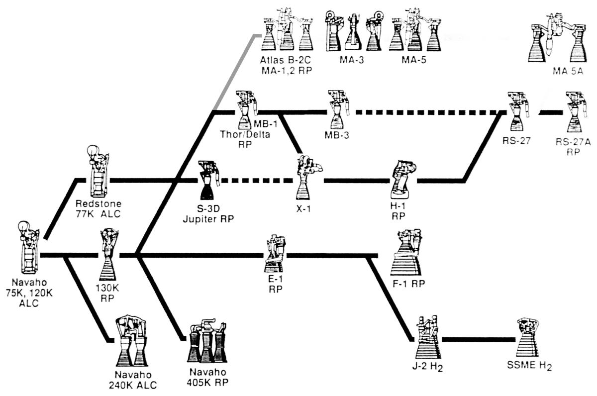
NAA/Rocketdyne Engine Evolution |
Although the North American Aviation Navaho guided missile never carried a human, it was an important exercise that led to numerous rocket engine designs and other technologies important to U.S. missile and space programs. Navaho was the North American Aviation response to a U.S. Army Air Forces 31 Oct 1945 request for proposals aimed at developing long-range surface-to-surface cruise missiles capable of carrying atomic bombs. Because the U.S. Army Air Forces/U.S. Air Force (USAAF/USAF) continually expanded both range and payload requirements, North American Aviation got an elaborate education in many aspects of rocket design, including engines. |
The Players
At the end of WWII, only two American commercial enterprises, Aerojet Engineering and Reaction Motors, Inc., were in the liquid-fueled rocket engine business. A few others, including Bell Aircraft, General Electric, M.W. Kellogg, Jet Propulsion Laboratories and NACA Cleveland, were dabbling in rocketry, but only Aerojet and RMI were actually building rockets. [Kraemer]
Reaction Motors, Inc. (RMI)
RMI grew out of a group of American Interplanetary Society (later American Rocket Society) members. Starting in 1930, the group experimented with rockets and rocket motors, perfecting a regeneratively-cooled liquid rocket engine in 1938. In 1941, the group formed Reaction Motors, Inc. in Pompton Planes, New Jersey to compete for a U.S. Navy contract. In 1943, RMI demonstrating an ethanol/LOX-fueled jet-assisted takeoff engine for a Martin PBM-5 aircraft. In 1945, RMI secured a U.S. Army contract that resulted in the alcohol/LOX XLR11 rocket engine that powered the Bell X-1, X-1A, X-1B and X-1D, along with M2-F2, M2-F3, HL-10, X-24A and X-24B lifting bodies. RMI also developed the ammonia/LOX XLR99 rocket engine that powered the North American X-15 research aircraft. Thiokol Chemical Corp. acquired RMI on April 17, 1958. [http://www.astronautix.com/r/reactionmotors.html, https://en.wikipedia.org/wiki/Reaction_Motors]
 |
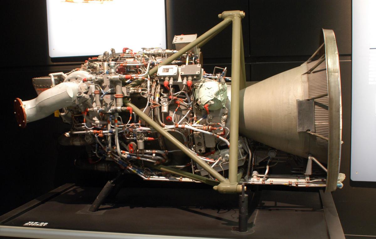 |
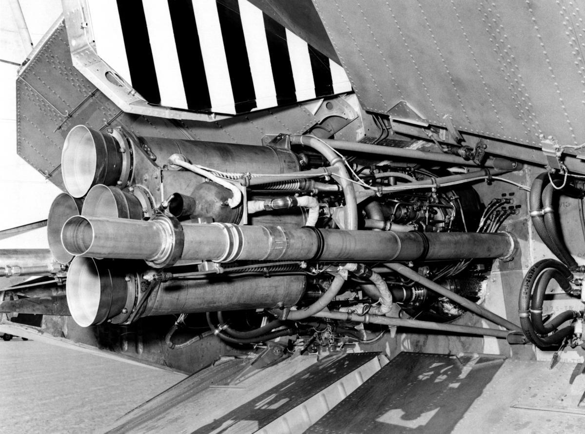
| RMI XLR11 Rocket Engine in Martin X-24A (NASA) | RMI XLR99 Rocket Engine (USAF) |
 |
| First U.S. Jet-Assisted Takeoff |
Aerojet
Starting in 1936, Professor Theodore von Kármán, who was director of the Guggenheim Aeronautical Laboratory at the California Institute of Technology (GALCIT), hosted a series of occasional informal meetings for persons interested in spaceflight. Their discussions eventually led to a small solid-rocket motor that was mounted to an ERCO Ercoupe airplane and tested by USAAF Captain Homer Boushey on 16 Aug 1941. The jet-assisted takeoff (JATO) halved its takeoff distance and resulted in an order for JATO rockets from the U.S. Army Air Forces. Aerojet Engineering Corp (Aerojet) was founded on 19 Mar 1942 to manufacture these rockets. Unable to get funding from banks, Aerojet sold a majority interest to General Tire, which funded additional research into both solid and liquid rockets. The Aerojet division branched into nearly all aspects of rocketry and became quite successful. Aerojet merged with Pratt & Whitney Rocketdyne in 2013, becoming Aerojet Rocketdyne Holdings. We shall be learning more about Aerojet later in this series. [http://www.astronautix.com/a/aerojet.html, https://en.wikipedia.org/wiki/Aerojet]
Rocketdyne
Established in 1928, North American Aviation, Inc. (NAA) became the most prolific builder of WWII aircraft, manufacturing 42,683 medium bombers, fighters and trainers for the war effort. Determined to stay in aviation after WWII ended, Chairman James Howard "Dutch" Kindelberger and President Lee Atwood decided that in addition to maintaining its core military aircraft business, NAA would sink some of its war profits into guided missiles. They stole William "Bill" Bollay, who was head of the U.S. Navy Bureau of Aeronautics' Power Plant Development Branch, and assigned him the task of building a rocket team. Bollay hired the best people he could find and was soon testing rocket engines in the newly-established Aerophysics Laboratory parking lot. The Aerophysics Laboratory was relocated and renamed the Missile and Control Equipment (MACE) Division in 1948, and then spun off as a separate division named Rocketdyne in 1955. Rocketdyne achieved enormous success in the rocket field, as we shall see as this series progresses.[Kraemer]
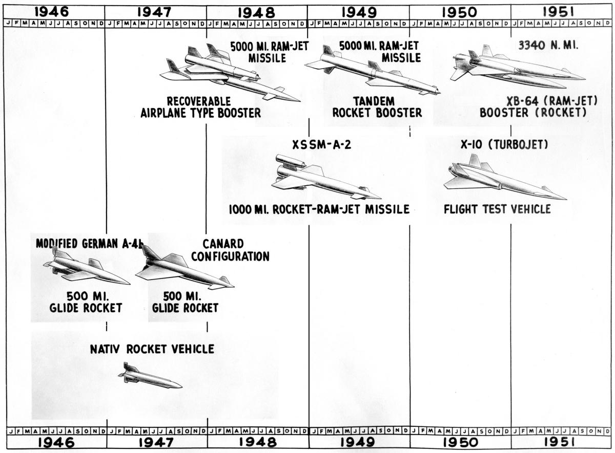 |
| MX-770/Navaho Evolution |
MX-770
Bill Bollay decided to submit a bid for the surface-to-surface missile the USAAF had requested on 31 Oct 1945. Using the German A-4b and A9 winged guided missile as a starting point, his team proposed a supersonic boost-glide missile with a 500 mile range and a 1,984 lb payload. NAA was awarded contract W33-038-ac-1491 on 24 Mar 1946 for a missile designated Materiel Experimental No. 770 (MX-770), which became the Navaho program. As a first example of Navaho's requirements bloat, the USAAF increased the payload to 3,000 lb just three months after the contract was awarded.
MX-770 System Development
 |
| NATIV/RTV-A-3(USAF) |
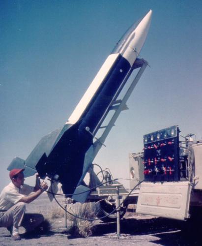
NAA had a lot of ground to cover before it could produce a workable missile. Like the German V-2 development team, NAA had to perfect supersonic airframes, guidance systems, propulsion systems, and the logistics to glue it all together. Captured German hardware and data would expedite the process by forming a basis for studies. NAA initially intended to refine the German A4b and A9 into workable missiles, but studies soon confirmed that both were unstable. Like the V-2 development team, NAA built a series of seven sub-scale rockets, the North American Test Instrument Vehicles (NATIV, also RTV-A-3). These were13.4 ft high, 1.5 ft in diameter, had a fin span of 4.29 ft and weighed 1,320 lb. Six launches were attempted, and of the four that actually left the launch rail, one failed shortly after launch, two were partial successes, and one a complete success where the 2,608 lbT rocket engine boosted a NATIV to Mach 2.23 and an altitude of nearly 60,000 ft. [http://www.astronautix.com/n/nativ.html, Landis Part 1]
 |
| Early MX-770 Cruise Missile Concept (NAA) |
In the mean time, studies of the original boost-glide concept revealed that the planned complex trajectory would be range-limited and difficult to control with any accuracy. In addition, on 18 Sep 1947 the U.S. Air Force had become an autonomous military branch. The U.S. Army was now responsible for missiles with ranges below 1,600 km, and the USAF responsible for missiles with ranges greater than 1,600 km. MX-770 now had to have a range of at least 1,600 km. A pure rocket could not achieve this, so NAA decided to redesign MX-770 as a ramjet-powered cruise missile boosted to ramjet ignition speed by a rocket engine. This three-phase program began in February 1947. Phase 1 was intended produce a missile with a 1,600 km range that could carry a 3,000 lb warhead. Phase 2 would extend the range to as much as 4,800 km, and Phase 3 would again extend the range to intercontinental proportions — 8,000 km with a 9,920 lb warhead.
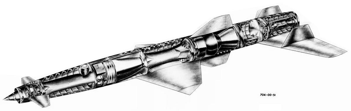
In January 1948 the MX-770 project was redesignated XSSM-A-2. Also called Navaho I and NA-704, it consisted of an integrated rocket booster and two cruise ramjets. XSSM-A-2 was 65 ft high, 5.5 ft in diameter, had a span of 20.6 ft and was estimated to weigh 50,000 lb. NAA developed a 75,000 lbT XLR43-NA-1 rocket engine for the XSSM-A-2.
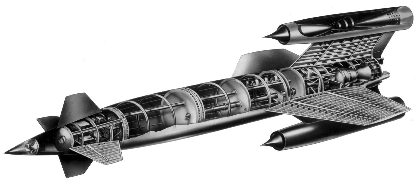 |
| NAA NA-704/XSSM-A-2 (NAA) |
In April 1950 the USAF cancelled the XSSM-A-2 and abandoned the three completed airframes. The USAF instructed NAA to pursue a new design, now called Navaho II that could deliver a 4,740 lb warhead over a 6,334 mile range. This version mounted a ramjet-powered cruise stage atop a rocket booster stage.
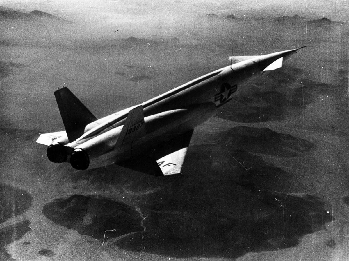 |
| NAA X-10 in Flight (USAF) |
This was yet another three phase program.
Phase 1 would consist of a Westinghouse J40 turbojet-powered reusable drone, designated X-10, which would verify the cruise stage structure, aerodynamics, guidance and control. With its delta wings cropped at the Mach angle, variable inlets, canards, and ability to resist Mach 2 heating, it was more advanced than anything else flying. The X-10 was 66.17 ft long, 5.61 ft in diameter and had a span of 28.8 ft. It weighed 42,291 lb. Thirteen were completed and the one that remains is on display at the National Museum of the United States Air Force. [http://www.astronautix.com/n/navahox-10.html]
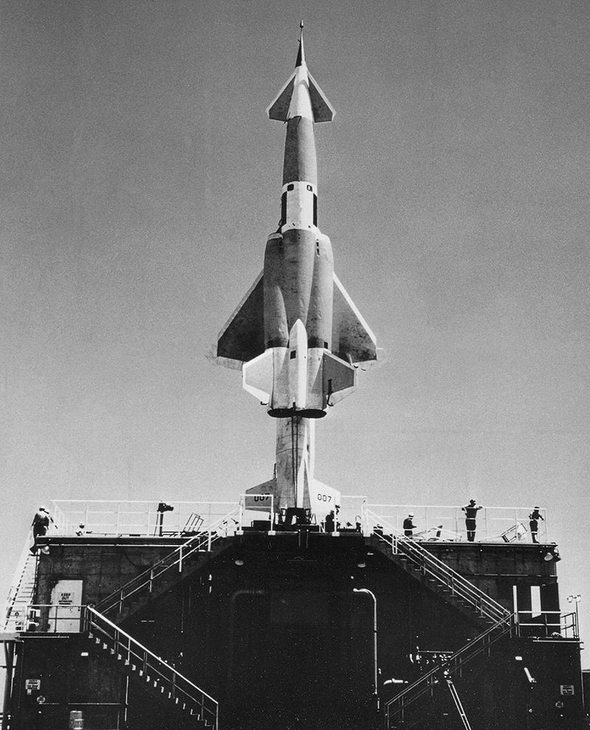
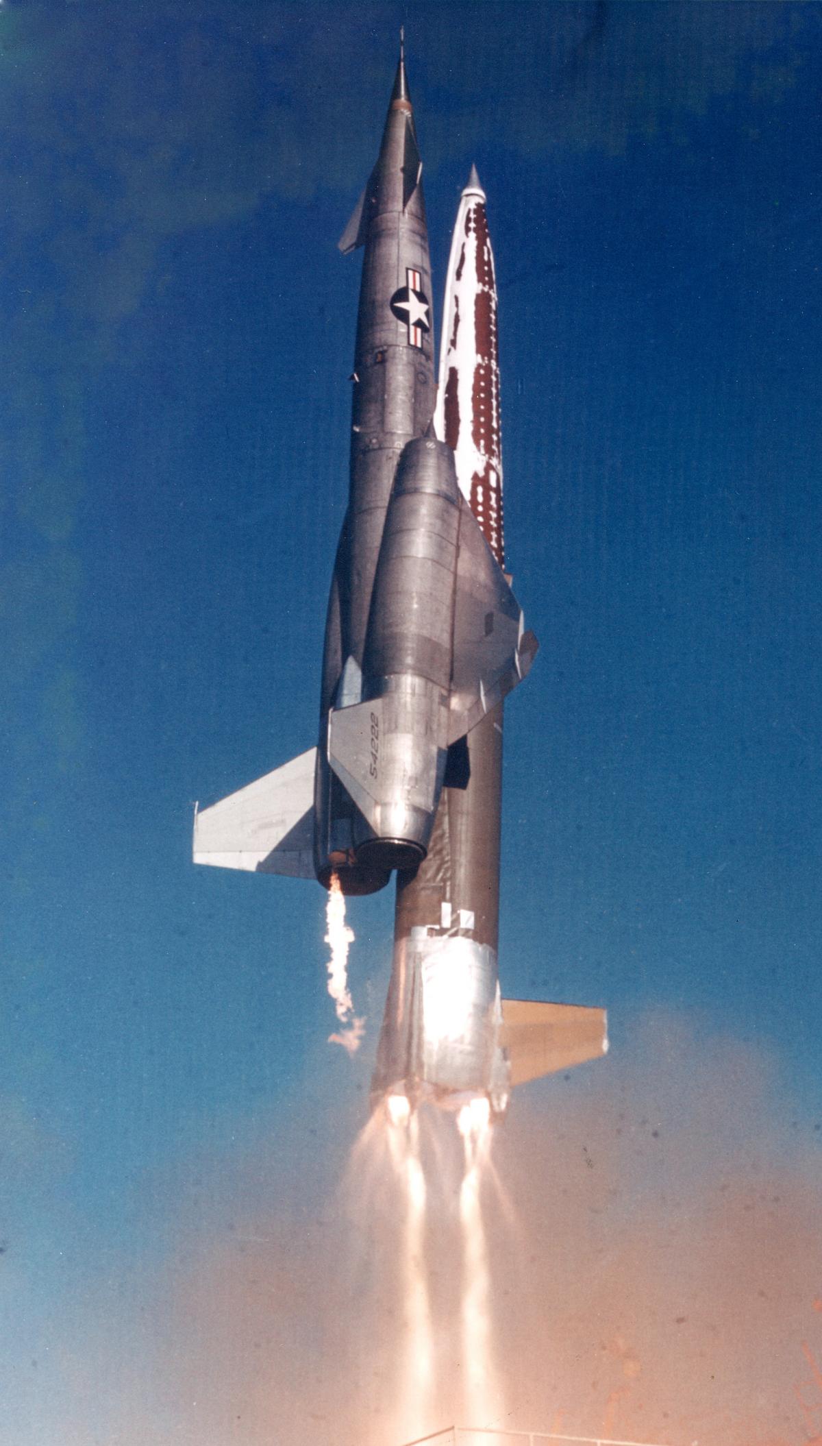
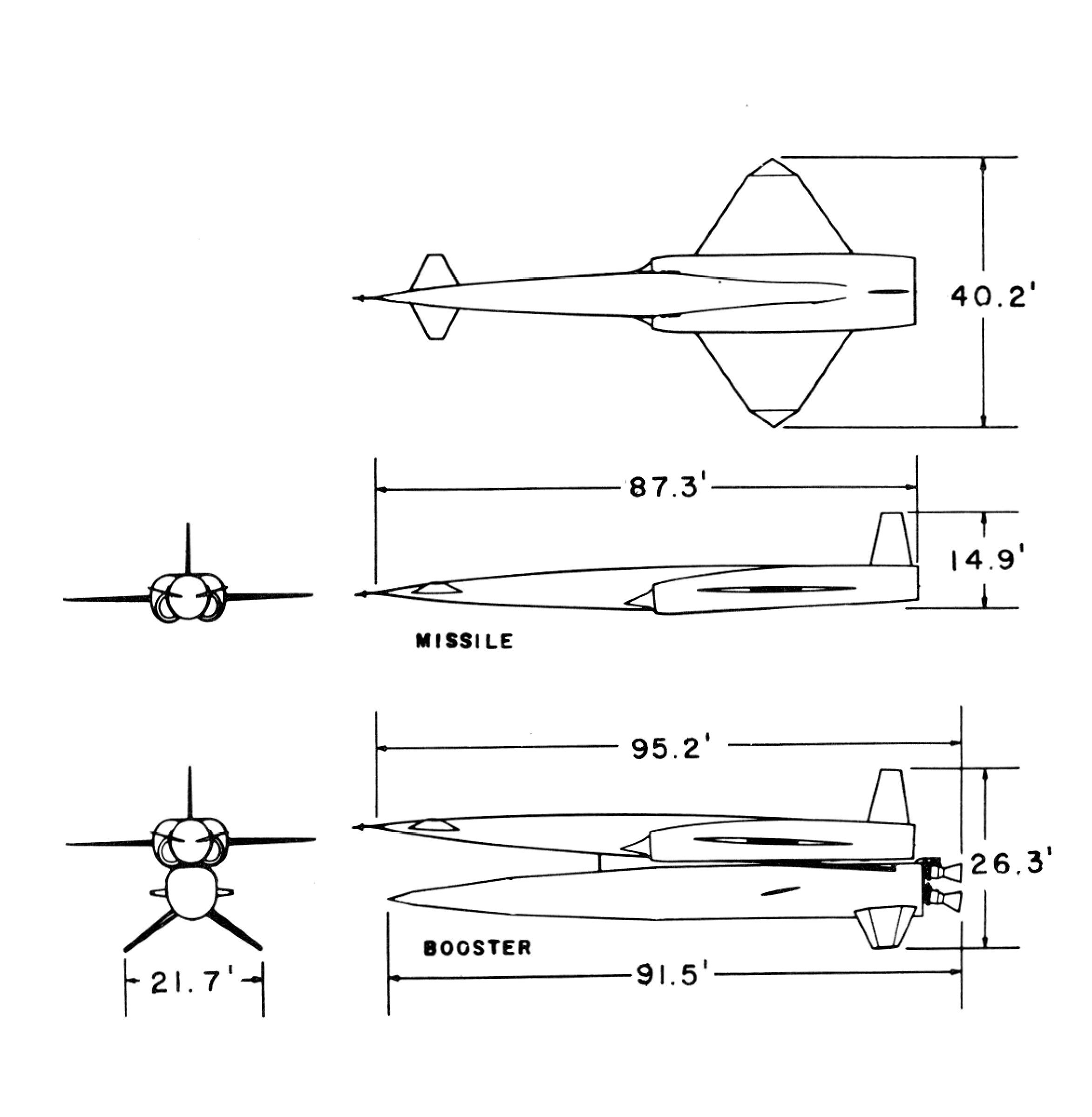
Phase 2, known variously as G-26, Navaho II, W13, XSM-64 and XSSM-A-4, was a 2/3 scale version of the final intercontinental version, which would test the rocket booster stage and ramjet cruise stage. It was 91 ft high, 5.77 ft in diameter, had a span of 28.6 ft and weighed 158,470 lb. The G-26 was to be powered by a pair of new 120,000 lbT XLR71-NA-1 (later 135,000 lbT XLR83-NA-1) rocket engines and twin Curtiss-Wright XRJ47-W-5 ramjets. Around 12 G-26 models were completed, but none of the few that were launched were completely successful. The sole surviving example was destroyed by Hurricane Matthew on 7Oct 2016. [http://www.astronautix.com/n/navahog-26.html]
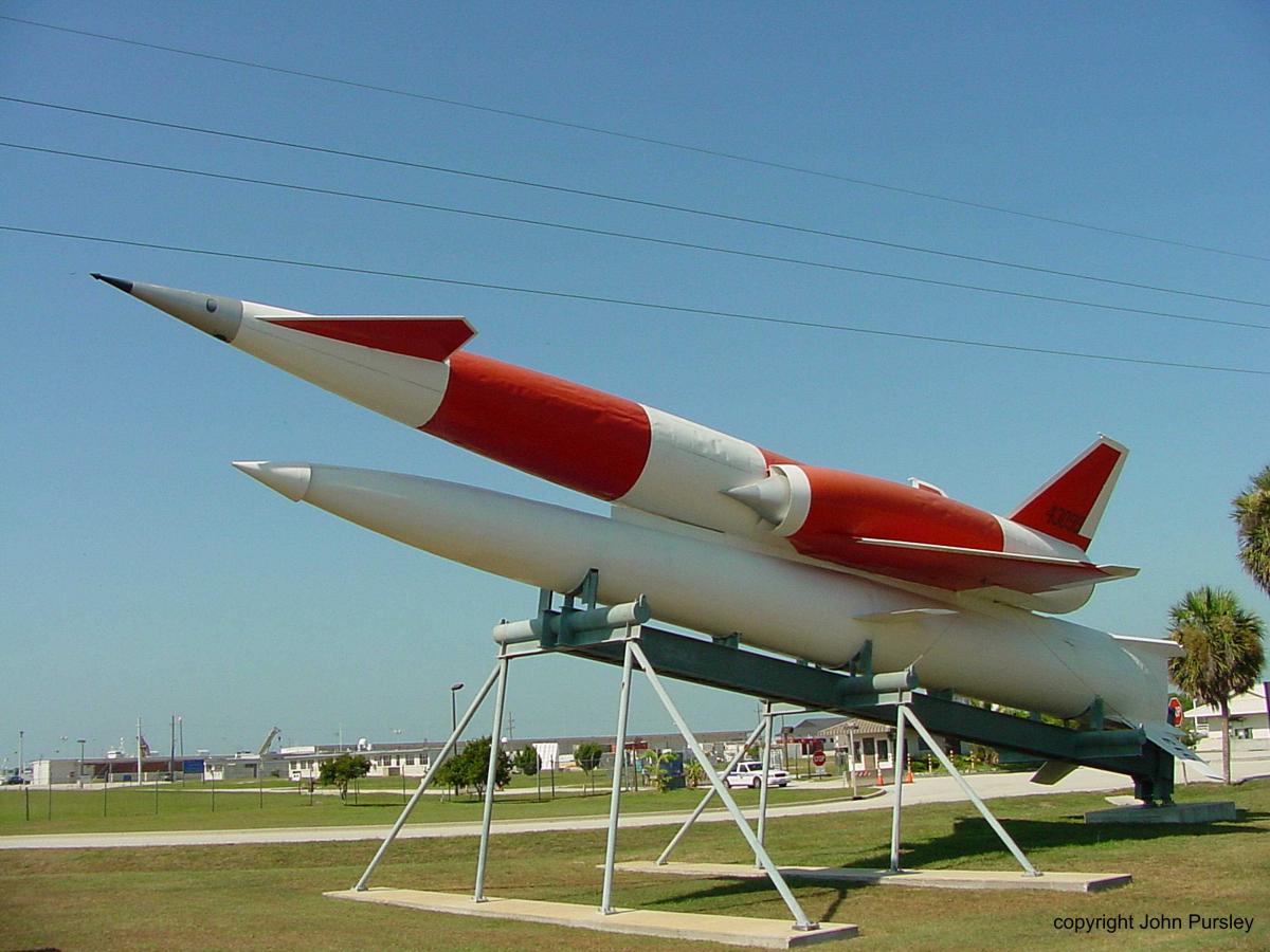 |
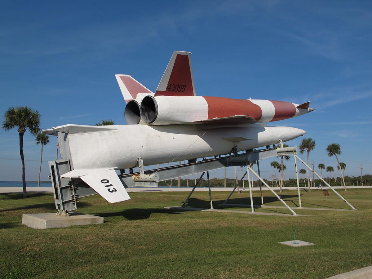 |
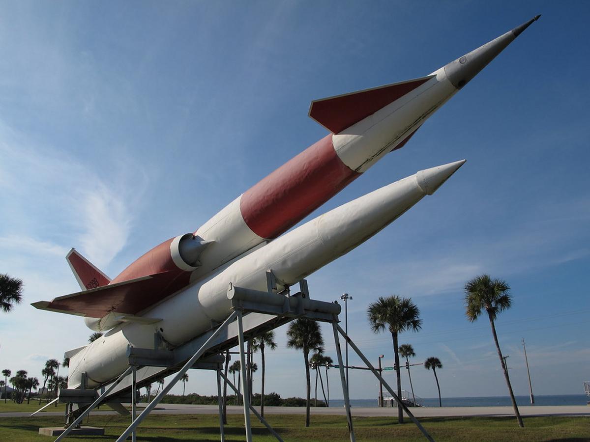 |
 |
 |
| At Cape Canaveral Air Force Station (Wiki) |
At Cape Canaveral Air Force Station (Kelly Michaels) |
At Cape Canaveral Air Force Station (Kelly Michaels) |
Before Launch (USAF) |
Launch (USAF) |
Phase 3, known as G-38, Navaho III, SM-64A, SSM-A-6, W36 and WS-104A, was to be powered by three 135,000 lbT XLR-83-NA-1 rocket engines and twin Curtiss-Wright XRJ47-W-5 ramjets. It was to be 213 ft high, 7.77 ft in diameter, have a 40.19 ft span, and weigh 289,990 lb. Before any G-38s could be completed the USAF determined that intercontinental ballistic missiles were superior to air-breathing intercontinental cruise missiles and cancelled the Navaho program. [http://www.astronautix.com/n/navahog-38.html]
 |
 |
| (USAF) | |
MX-770 Engine Development
The 75K Engine
Although Bollay had assembled a fine rocket team, everyone was ex-military or from academia. Someone with practical engine experience was needed, and Bollay selected Samuel K. Hoffman, who had been Lycoming's chief engineer and then a Penn State engineering professor. To gather technical information, Hoffman and his team met with Wernher von Braun and Konrad Dannenberg, who had been heavily involved with the Model 39a single-injector. Hoffman also hired Dieter Huzel, a Peenemünde lead test engineer, to design and build test facilities. Other Peenemünde team members also consulted to NAA, suggesting things like a rough-combustion cutoff device that saved numerous thrust chambers.
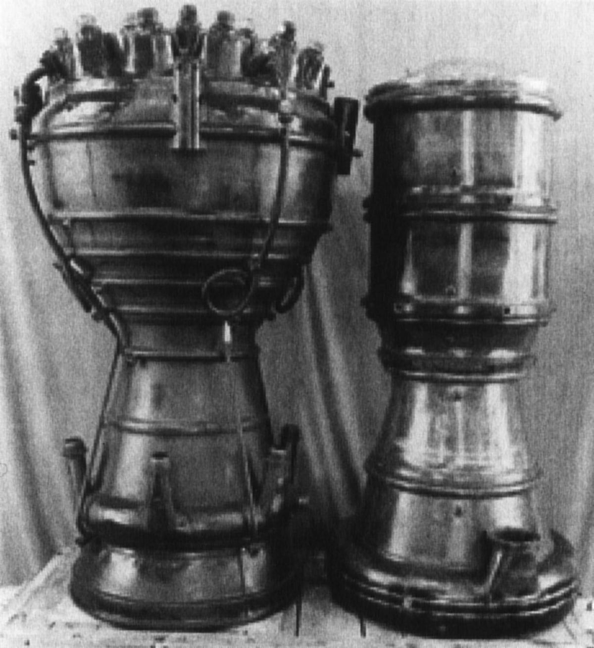
NAA's engine development began with two V-2 Model 39 systems, which NAA tore down, examined in detail, reassembled and tested. This was called the Mark I engine. Next, the German engine was redesigned using American fasteners, materials, o-rings, gaskets, fabrication techniques and engineering standards. Three NAA-704 Mark II (military designation XLR41-NA-1) engines were built and flow-tested but never hot-fired; the process was cut short in early 1947 when NAA got access to a Model 39a engine, which became the new starting point and resulted in the NAA-704 Mark III (XLR43-NA-1) engine. The NAA Mark III engine had a thrust rating similar to the V-2, but was intended to be about 15% lighter. It still used a 75/25 mix of ethanol and water for fuel and LOX for the oxidizer.
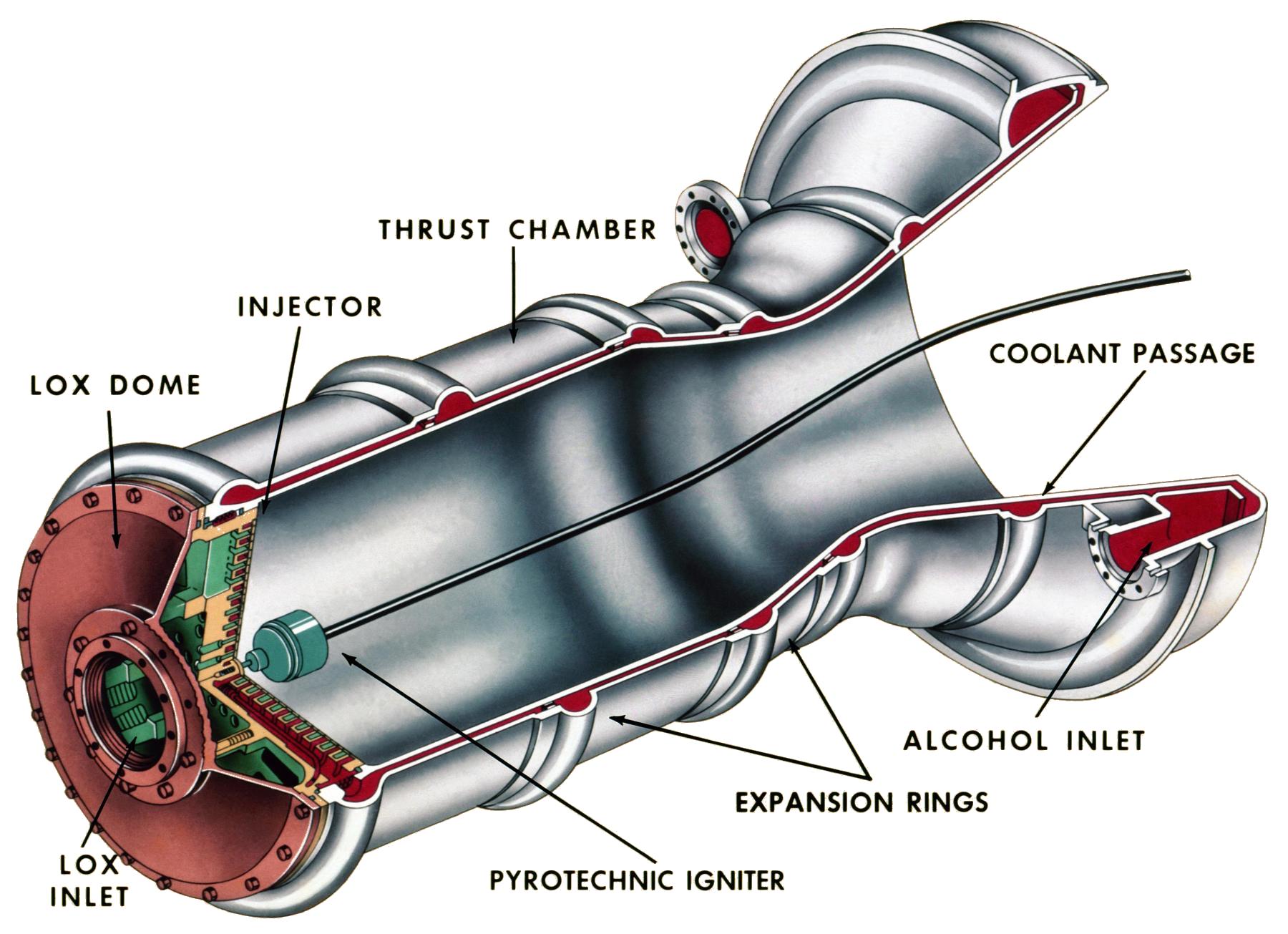
The new thrust chamber was cylindrical rather than spherical in shape, which streamlined the fabrication process considerably. The double-wall regenerative cooling scheme was retained, as was the film cooling, but rather than drilling holes in the inner thrust chamber wall to admit fuel, holes were instead drilled around the single injector periphery. The Germans had not been able to make the single large flat-plate injector work successfully, it being prone to combustion instability. NAA had the same problem at first, but through a process of trial-and-error, eventually arrived at a solution. A series of concentric rings with holes drilled into distribution manifolds comprised the new injector. Alternate rings injected fuel and then oxidizer. The initial injector used a triplet pattern with two fuel streams impinging on one LOX stream. The Mark III engine, with a single LOX feed line to the thrust chamber, was considerably simpler than the V-2.
When the USAF changed the requirements to include a 1,600 km range and 3,000 lb warhead, the resulting rocket required a thrust of about 75,000 lbT (the 75K engine), up substantially from the V-2's 55,000 lbT. NAA addressed this by increasing the chamber pressure to 318 psia while retaining the 15.3" nozzle throat diameter and 15° nozzle expansion half-angle. Engine length was increased slightly to achieve an expansion ratio of 3.61. This provided a thrust increase without much change to the engine dimensions.
The higher chamber pressure necessitated greater mass flow, so NAA also redesigned the 75K turbopump. The basic configuration of a central turbine with a pump on either side was retained, but a single shaft, supported by two bearings made the new turbopump much simpler. The new pump spun about 1,000 rpm faster than the V-2's and pumped about 25% more propellant. Like the V-2 turbopump, the 75K turbopump was powered by high-pressure, high-temperature steam formed by decomposing hydrogen peroxide. However, unlike the V-2's complex liquid permanganate system, the NAA design used a greatly simplified steam generator that housed 36 cobalt-plated metal screens to catalyze the H2O2.
 |
 |
.jpg) |
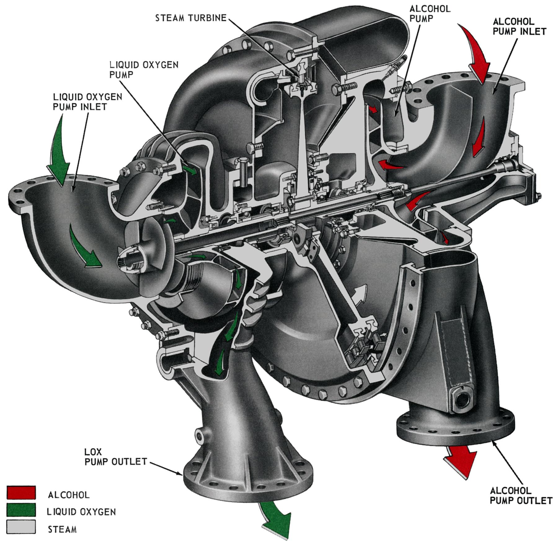 |
| The NAA XLR41-NA-1 (L) and the XLR43-NA-1 (R) Thrust Chambers (NAA) | NAA XLR43-NA-1 Cutaway. Note the injector detail and construction simplification as compared to the German Model 39A. (heroicrelics.org) | NAA XLR43-NA-1 Injector. Note the like-on-like doublet injector pattern. Also note the ring of tiny film cooling holes just inboard of the chamber inner wall. (heroicrelics.org) | NAA XLR43-NA-1 Turbopump. Note the simplification as compared with the German V-2 Turbopump. (heroicrelics.org) |
To test the 75K engine, NAA built a large vertical test stand, VTS-1, at Santa Susana, California. The testing process was anything but smooth. On 2 Mar 1950, the NAA team attempted its first test firing of the 75K thrust chamber. At that time the turbopump had not yet been integrated. NAA invited a bunch of VIPs to witness the test. When the countdown reached zero, the thrust chamber exploded. The design engineer had chosen mild steel as the material from which the LOX dome was constructed without realizing that it would become brittle when cooled to the -297°F LOX boiling temperature. The dome had shattered, making a huge fire. Nearly every part of the testing was a new experience and the development methodology was trial-and-error. The thrust chamber was prone to hard starting, which could damage the injector in the blink of an eye. Eventually a LOX recirculation scheme was developed to prevent LOX line bubbles, the ideal igniter location decided, and a water-cooled steel deflector was added to the test stand.
On 15 Nov 1950 the first full-up 75K American rocket engine, installed in VTS-1, successfully achieved main stage. Gradually, further problems were conquered, igniter location and propellant delivery were refined. But combustion instability continued to be a problem when the engine transitioned from pre-stage to main stage. Ultimately, the triplet injector was abandoned in favor of a doublet like-on-like injector where the injector holes were drilled so that groups of two fuel streams impinged on one another and groups of two LOX streams impinged on one another. The scheme worked and was the first example of a problem that had eluded the Germans being solved by the NAA team .
Another NAA accomplishment was to replace the relatively slow V-2 start process where propellants under tank head pressure were admitted to the thrust chamber and ignited, followed by turbopump activation. Instead, the NAA team changed the start sequence to simultaneously fully open the LOX valve and peroxide valve, and then 0.2 seconds later, fully open the fuel valve. This process worked very well and made starting a much easier process.
The 75K engine was quite an accomplishment for NAA. In about three years the team had succeeded in creating an engine with 20,000 lbT more thrust while weighing nearly 1,000 lb less than the V-2. Although it never saw service in the Navaho, it was refined into the NAA 75-110-A6 and -A7 engines that powered the U.S. Army Redstone and launched Americas first astronauts into suborbital flight. [Kraemer]
The 120K/135K Engines
In order to make the 240,000 lbT necessary to launch the Navaho II, NAA planed a pair of 120,000 lbT thrust chambers burning ethanol and LOX, but derivatives of the old Model 39a engine had reached their development peak. Starting with an injector similar to the 75K engine, NAA engineers created a new thrust chamber that was fueled by 92.5% ethanol at a chamber pressure of 438 psia and a nozzle area ratio of 4.16. A new approach was also required to cool this significantly more powerful thrust chamber.
On 5 Apr 1950, Edward A Neu, Jr., an engineer with RMI, applied for a patent (US 3,190,070) covering a new way of building thrust chambers. Neu shaped a collection of thin-walled steel tubes so they had the same longitudinal profile as a thrust chamber. He then assembled the tubes on a mandrel, added circumferential bands to counteract the interior pressure, and brazed the whole assembly together, forming a lightweight, stiff thrust chamber. Fuel was still used as a coolant, but rather than circulating from the bottom up, it was supplied to alternating tubes at the injector end. Fuel then traveled down the chamber wall into a manifold at the nozzle exit, which redirected it back up the adjacent tubes to the injector, where it was then burned. The thin-walled tubes had much better heat transfer characteristics than the old V-2 and 75K mild steel weldments. NAA found that a thrust chamber constructed in this manner was superior in every respect to the old technology, and it was this construction that was used for all subsequent NAA and Rocketdyne engine designs.
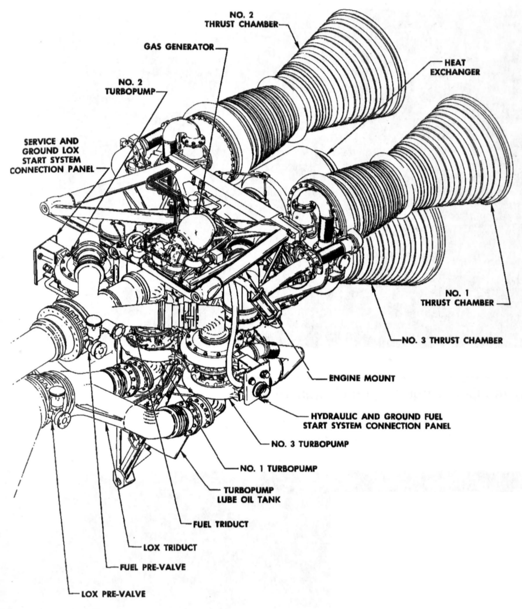
The increased chamber pressure, with its increased propellant flow rate, dictated a new turbopump. However, instead of powering the new one with steam, NAA engineers came up with a scheme to burn a small portion of the propellants in a separate gas generator, which produced fuel-rich hot gas that drove the turbine. The gasses were fuel-rich to limit their temperature to values acceptable to the turbine. This was considerably simpler and more efficient than the old catalyzed H2O2. The new turbopump also did not drive the pumps directly as had been the previous practice. Instead, the smaller turbine turned at a higher speed and drove the pumps through a reduction gear train. This arrangement was not only more compact, but, as we shall see, was capable of being enlarged almost without bounds. Its progeny went on to power Atlas, Jupiter, Thor, Delta and Saturn I. As with the V-2 and 75K engine, a heat exchanger in the turbine's exhaust vaporized LOX to pressurize the LOX tank. This new twin-chamber rocket engine was designated XLR71-NA-1. When still more thrust was desired, NAA engineers again increased the chamber pressure, achieving 135,000 lbT. [Kraemer, http://www.astronautix.com/x/xlr71-na-1.html]
 |
 |
 |
 |
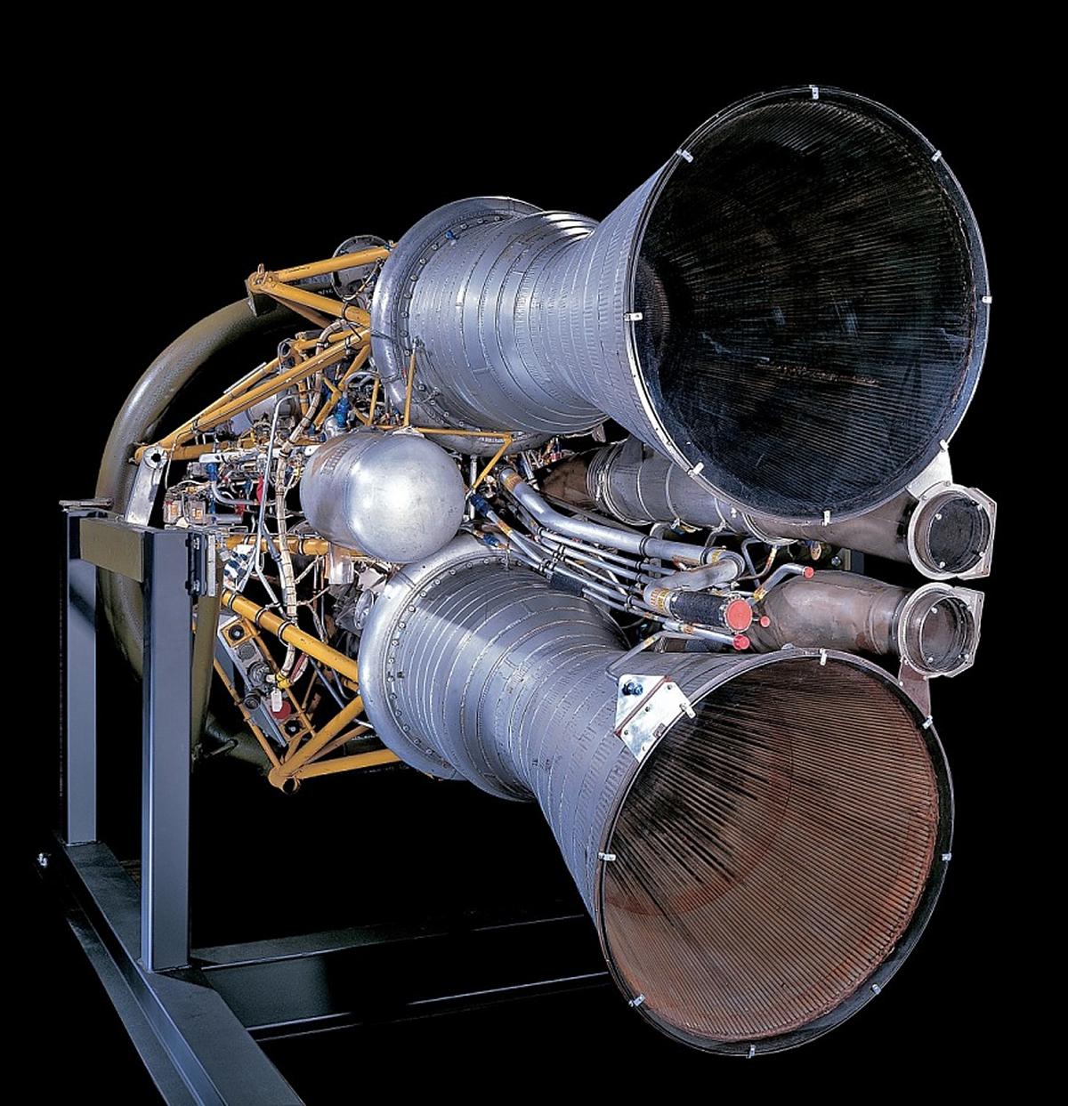
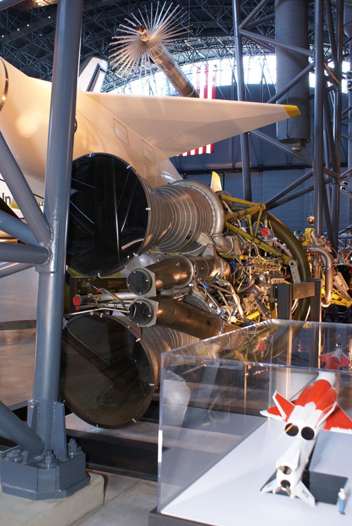
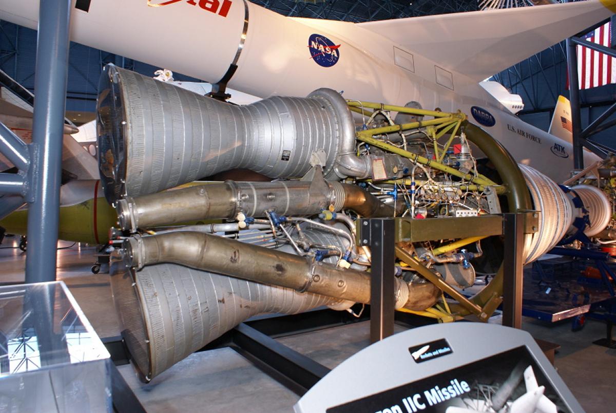
| NAA XLR71-NA-1 (NASM) | NAA XLR71-NA-1 (heroicrelics.org) | NAA XLR71-NA-1 (heroicrelics.org) | NAA XLR71-NA-1 (heroicrelics.org) |
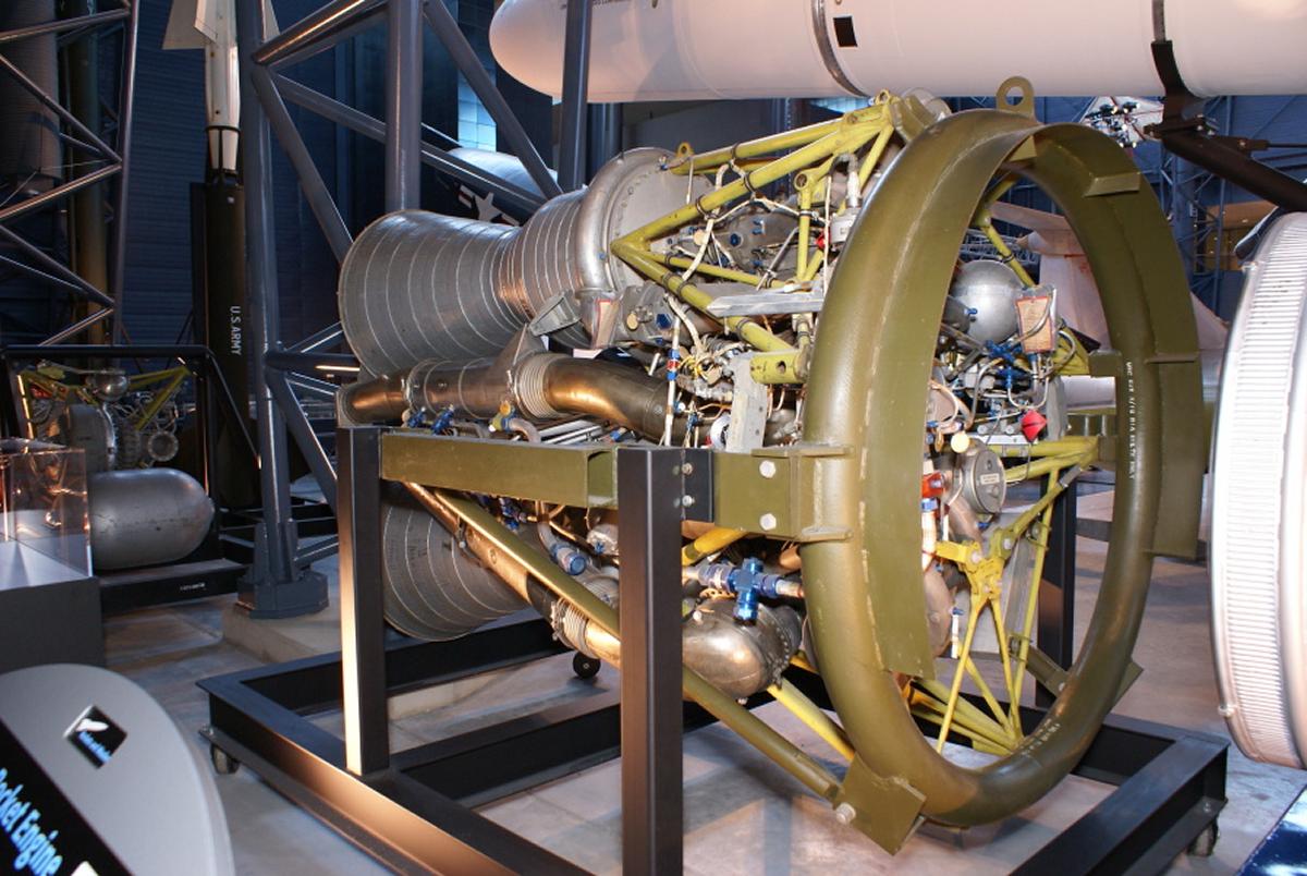 |
 |
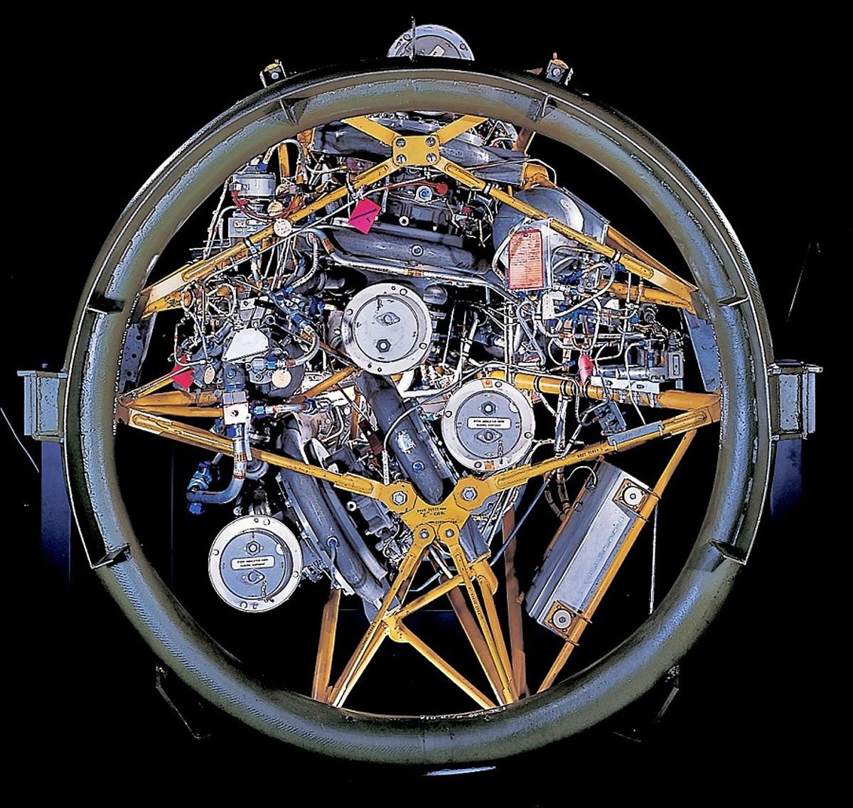 |
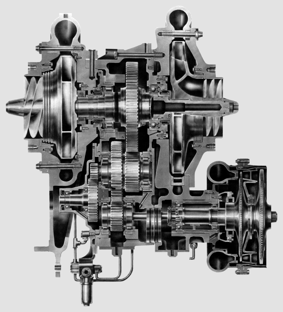 |
| NAA XLR71-NA-1 (heroicrelics.org) | NAA XLR71-NA-1 (heroicrelics.org) | NAA XLR71-NA-1 (NASM) | NAA XLR71-NA-1 Mark III Turbopump (heroicrelics.org) |
The Navaho III booster required a thrust of 405,000 lbT, which could be achieved by upping the thrust of the XLR71-NA-1 to 135,000 lbT. There was also a move to replace ethanol with the more powerful JP-4 jet fuel. This work was done without much change and resulted in the XLR83-NA-1, which consisted of three thrust chambers. This configuration was extensively tested at Santa Susana, and although tested in twin-chamber configuration on the Navaho II, was never flight tested. [Kraemer, http://www.astronautix.com/x/xlr83-na-1.html]
 |
| The NAA XLR83-NA-1 Three-Chamber Cluster (NAA) |
References
Kraemer, Robert S. Rocketdyne: Powering Humans into Space (Reston, Virginia: AIAA, 2006)
Landis, Tony R. AFMC Flashback "Navaho Missile Program: Part 1" (WPAFB, Ohio: Air Force Materiel Command History and Museums Program, Apr 2020).
--- On To Part 4.1 ---
Send mail to
![]() with questions or comments about this web site.
with questions or comments about this web site.
![]()