The Titan Family (Wiki)
[http://www.astronautix.com/t/titan.html, https://en.wikipedia.org/wiki/Titan_(rocket_family)]
U.S. Manned Rocket Propulsion Evolution
Part 6: The Titan Missile
Compiled by Kimble D. McCutcheon
Published 1 Feb 2021; Revised 3 Aug 2022
The Titan Family (Wiki) |
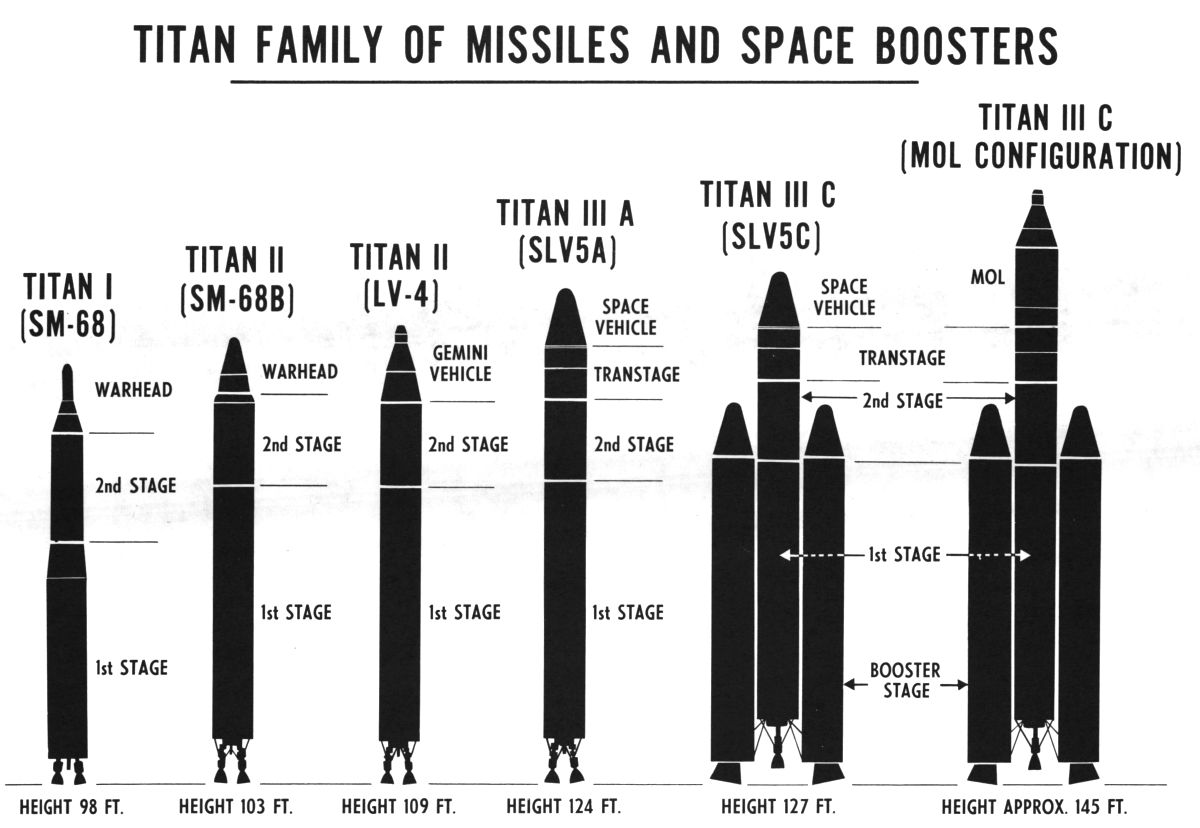
The U.S. Air Force created the Titan ICBM program in October 1955 as a backup in case Atlas ran into insurmountable development problems. What began as a series of studies into alternative engines, guidance systems and other components using non-Atlas contractors eventually grew into a full-fledged program. The Air Force chose Martin as the prime contractor and Martin produced a design substantially different from Atlas. Aircraft-like structure replaced the Atlas pressurized balloon construction. Not only was this construction about 2,300 lb lighter, but it helped increase Titan’s payload by 5,000 lb over that of Atlas E/F. Titan was also to be a true two-stage vehicle, with a two-chambered Aerojet General LR87 rocket engine powering Stage 1 and a single Aerojet LR91 engine for Stage 2. The first Titan flew on 6 Feb 1959. The design concept was almost continually improved and refined to meet defense and low-earth-orbit launch requirements. A total of 368 Titans were built, the last one being launched on 19 Oct 2005. Only a small subset of Titan variants will be discussed here – those up to and including the Gemini Launch Vehicle. [http://www.astronautix.com/t/titan.html, https://en.wikipedia.org/wiki/Titan_(rocket_family)] |
 Martin Matador (Wiki) |
Martin
Glenn L. Martin initially founded the Glenn L. Martin Company on 16 Aug 1912, briefly merged with the Wright Company in 1916, and re-formed the Glenn L. Martin Company on 10 Sep 1917. The new company eventually settled in Baltimore, Maryland where it primarily built bombers, seaplanes and transports through WWII. After the war, Martin had some success in with small commercial airliners, but also branched out into designing and building rockets and guided missiles. The Martin organization’s various names included The Martin Company, Martin-Marietta and Lockheed Martin. [https://en.wikipedia.org/wiki/Glenn_L._Martin_Company]
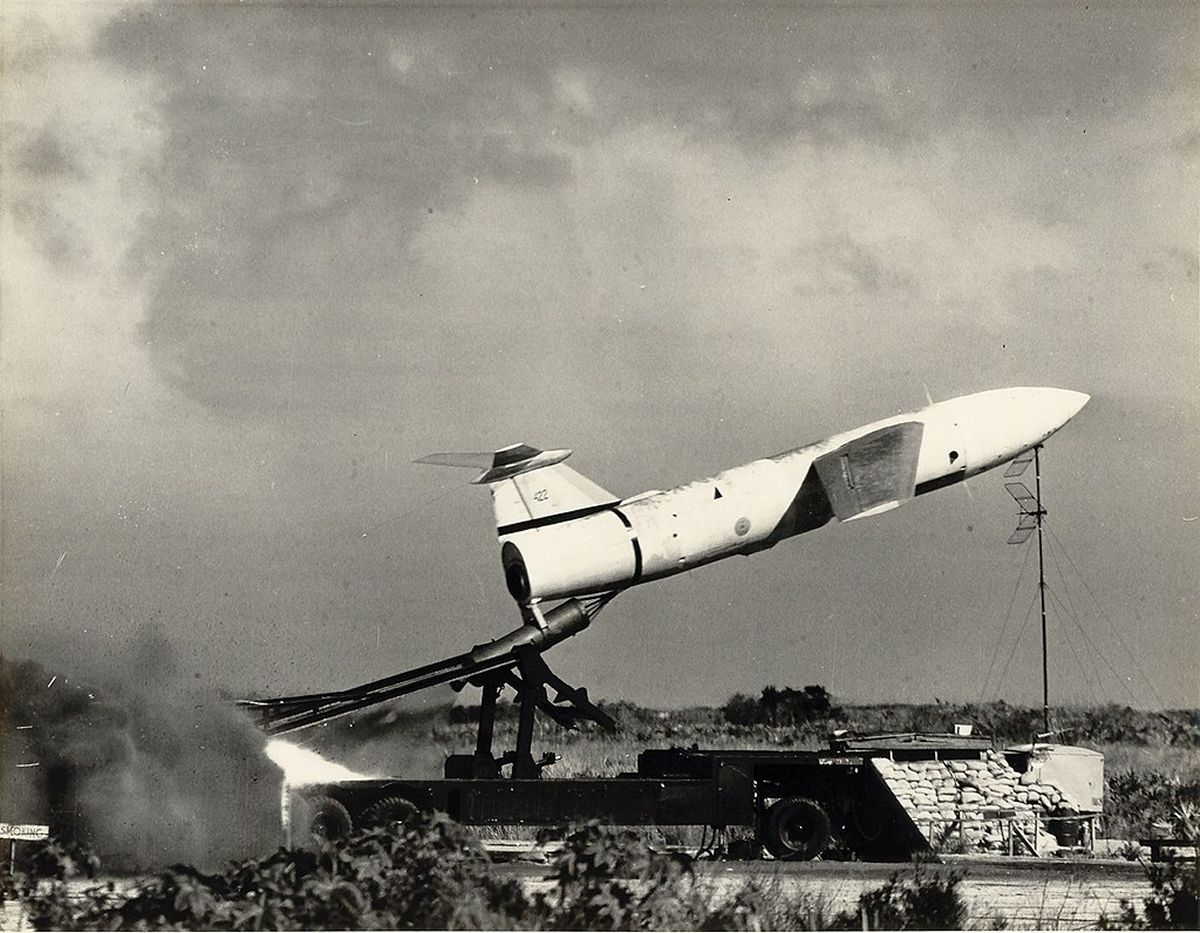
The MGM-1 Matador was the first successful Martin missile, and also the first U.S. designed surface-to-surface missile; it first flew on 12 Jan 1948. A cruise missile, it was launched with an Aerojet JATO solid rocket motor and used an Allison J33-A-37 turbojet for cruise flight. It had a range of about 600 miles and carried a W5 50KT nuclear warhead. A total of 1,000 were built. Martin followed the Matador with an improved version, the MGM-13 Mace. [http://www.astronautix.com/m/matador.html]
Titan ICBMs
Titan I
The Titan I (also LGM-25A and SM-68A) was the second U.S. ICBM with capabilities roughly equivalent to Atlas E/F. Like Atlas, the Titan I was based in underground silos and lifted to the surface using an elevator. Titan still required RP-1 and LOX to be loaded after the launch authorization. It took 7.5 minutes to raise the missile to ground level and about 15 minutes to load the propellants. A total of 54 missiles were deployed and operational between 1962 and 1965.
The Titan I Stage 1 was initially powered by an Aerojet LR87-AJ-1 engine; the first improved XLR87-AJ-3 was released from production in November 1959. The use of two gimbaled thrust chambers allowed control of roll, pitch and yaw. A single gimbaled LR91-AJ-1 powered Stage 2; this was replaced with production XLR91-AJ-3 in November 1959. Turbopump exhaust exiting via four gimbaled vernier nozzles facilitated Stage 2 control.
Titan I used a combination of inertial guidance for the first minute or so of flight and radio guidance for the remainder of the boost phase. A Western Electric AN/GRW-5 guidance radar tracked a transponder on the missile, a Univac AN/GSD-1 Athena guidance computer at the launch control center analyzed the missile’s performance and sent coded radio commands during the remainder of the first and second stage burns, ultimately terminating the burn at the desired speed, final-checking the trajectory, arming the warhead and separating the reentry vehicle from the second stage.
 Titan Internal Structure (heriocrelics.org) |
Titan II (also LGM-25C)
The Air Force had insisted that Titan I use the RP-1 and LOX propellant combination, but almost from the beginning, Martin and Aerojet were suggesting improvements based on storable propellants that would allow the missile to be launched directly from its silo, thereby eliminating the complex Titan I silo elevator system and reducing launch delays to around a minute. In late 1959, the Air Force was considering a crewed space presence with projects such as the X-20A Dyna-Soar, Gemini B, Manned Orbiting Laboratory (MOL) and lifting-body space planes supporting MOL. All these programs required a more powerful launch vehicle. By early 1960, the studies were done, the decisions were made and Martin had a Titan II production contract by May.
Although Titan II was essentially the same size as Titan I, many changes were made to accommodate new propellant combination and upgraded engines with a sizeable thrust increase. Titan II could sit in a silo fully fueled and ready to launch at a moments notice for a practically indefinite time period.
Titan II also got a new inertial guidance system designed by Massachusetts Institute of Technology’s Draper Laboratories and built by AC Spark Plug. This eliminated the radio link and ground-based computers that had been part of the Titan I guidance system.
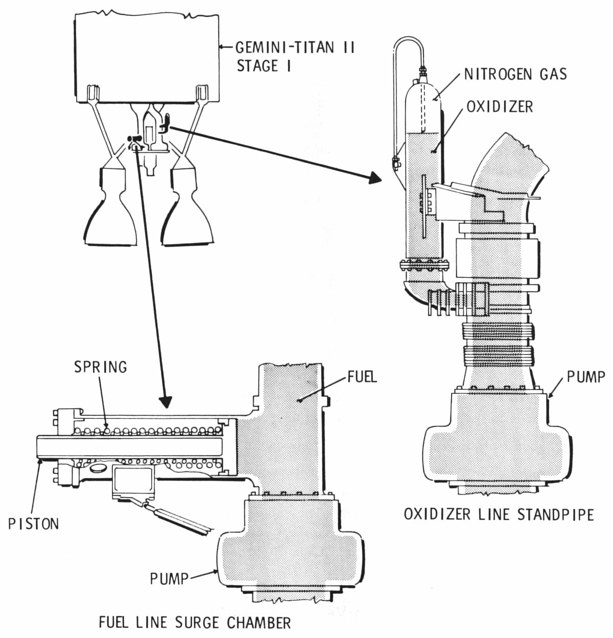
Titan II first flew on 16 Mar 1962, and its development program, while not without incident, was much more successful than Titan I. Of the 33 test launches at least 23 were successful and the last 13 were all successful. The failures included umbilicals that didn’t unplug, premature engine shutdowns, an oxidizer leak, a fuel valve failure, a fuel pump leak, and a gas generator failure. Each of these had to be investigated and solved. The most serious problem was a longitudinal oscillation of the entire rocket that became known as “pogo” vibration. This approximately 11 Hz vibration had a maximum amplitude of 5.0g on one test flight. While this was undesirable for a missile system, it was downright unacceptable for a human-rated rocket (NASA wanted less than ±0.25g) and had to be addressed before Titan II was acceptable to for NASA's Gemini program. Engineers reasoned the pogo vibration was a resonance of the long propellant ducts, rocket structure and engine thrust. The natural vibration of combustion would set up sympathetic vibration in the propellant plumbing and structure, which would affect the engine thrust. The problem was cured by installing an accumulator standpipe in the oxidizer feed duct and a spring-loaded accumulator in the fuel feed duct. [Hunley, 164-165]
Starting in 1963, all Titan I missiles were pulled out of the ground and scrapped, their silos converted to accept Titan II missiles, and by the end of 1964 all 54 silos had Titan II missiles equipped with 9MT W-53 warheads, the most powerful hydrogen bomb ever fielded by the U.S. Titan II CEP was 1.0 mile and the missiles remained in service until 1987.
When solid-propellant ICBMs arrived on the scene, the Titan II missiles were refurbished for use as space launch vehicles. A total of 131 (23 development and 108 production) were built.
| Component / Resource | Titan I | Titan II |
|---|---|---|
| Relays | 49 | 7 |
| Umbilicals | 32 | 4 |
| Valves and Regulators | 91 | 16 |
| Periodic Checkout Functions | 322 | 35 |
| Launch Functions | 230 | 23 |
| Major Underground Structures | 42 | 18 |
| Underground Tunnels (ft) | 6,000 | 945 |
| Squadron Power Requirements (KW) | 12,000 | 2,700 |
| Squadron Chassis Requirements | 945 | 414 |
| Squadron Elevator Components | 13,050 | 0 |
| Ground Guidance Rack | 111 | 36 |
| Squadron PTPS Components | 5,640 | 1,355 |
| Electrical Cables | 194 | 80 |
| Electrical Conductors | 3,500 | 1,900 |
| Electrical Terminations | 8,100 | 3,840 |
[Gemini-Titan II Press Handbook, [http://www.astronautix.com/t/titanii.html, https://en.wikipedia.org/wiki/LGM-25C_Titan_II]
| Titan I | Titan II | Titan GLV | |
|---|---|---|---|
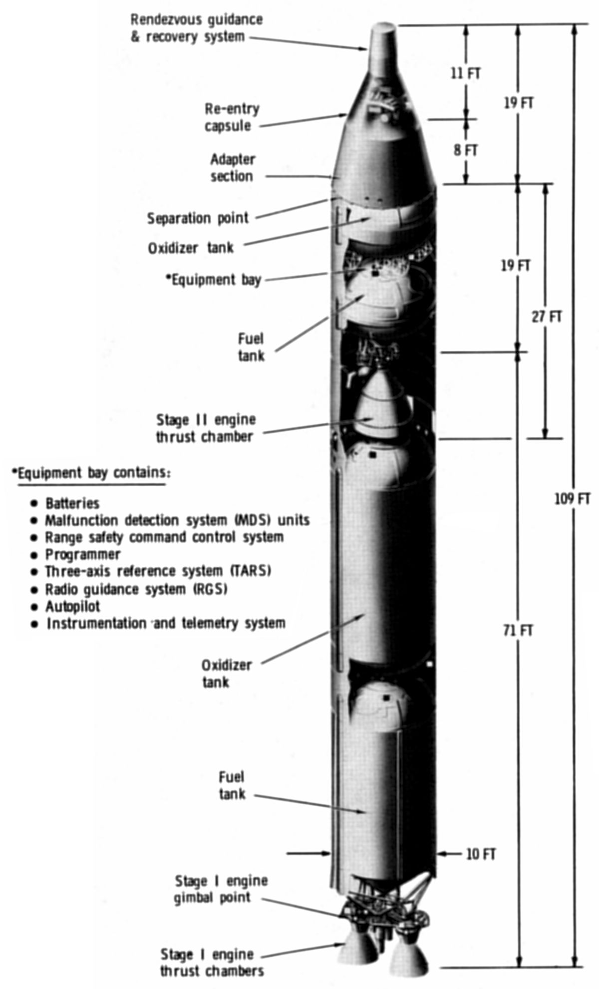
| Height (ft) | 101.00 | 103.00 | 109.00 |
| Diameter (ft) | 10.00 | 10.00 | 10.00 |
| Gross Weight (lb) | 231,798 | 339,000 | 331,500 |
| Thrust, Stage 1, SL (lbF) | 291,330 | 430,000 | 430,000 |
| Thrust, Stage 2, Vac (lbF) | 80,000 | 100,000 | 100,000 |
| Engines, Stage 1 | LR87-AJ-3 | LR87-AJ-5 | LR87-AJ-7 |
| Engine, Stage 2 | LR91-AJ-3 | LR91-AJ-5 | LR91-AJ-7 |
| Fuel | RP-1 | Aerozine 50 | Aerozine 50 |
| Oxidizer | LOX | N2O4 | N2O4 |
| Development Articles | 47 | 23 | 2 |
| Production Articles | 108 | 108 | 10 |
| Total Built | 155 | 131 | 12 |
| Warhead | W49 | W53 | NA |
| Warhead Yield (MT) | 1.44 | 8.9 | NA |
| Warhead CEP (mi) | 1.25 | 1.00 | NA |
Titan-Gemini Launch Vehicle (GLV)
Titan II was chosen for conversion into the project Gemini launch vehicle because it carried the largest payload of any U.S. ICBM, making it able to launch the two-man Gemini spacecraft into low earth orbit. At the time it was chosen, Titan was in an advanced state of development, making for a relatively trouble-free conversion. Since it used storable propellants, achieving launches during the narrow launch windows associated with spacecraft rendezvous was made operationally easier. The use of hypergolic propellants eliminated the need for an ignition system and greatly simplified airborne systems, thereby making them more reliable.
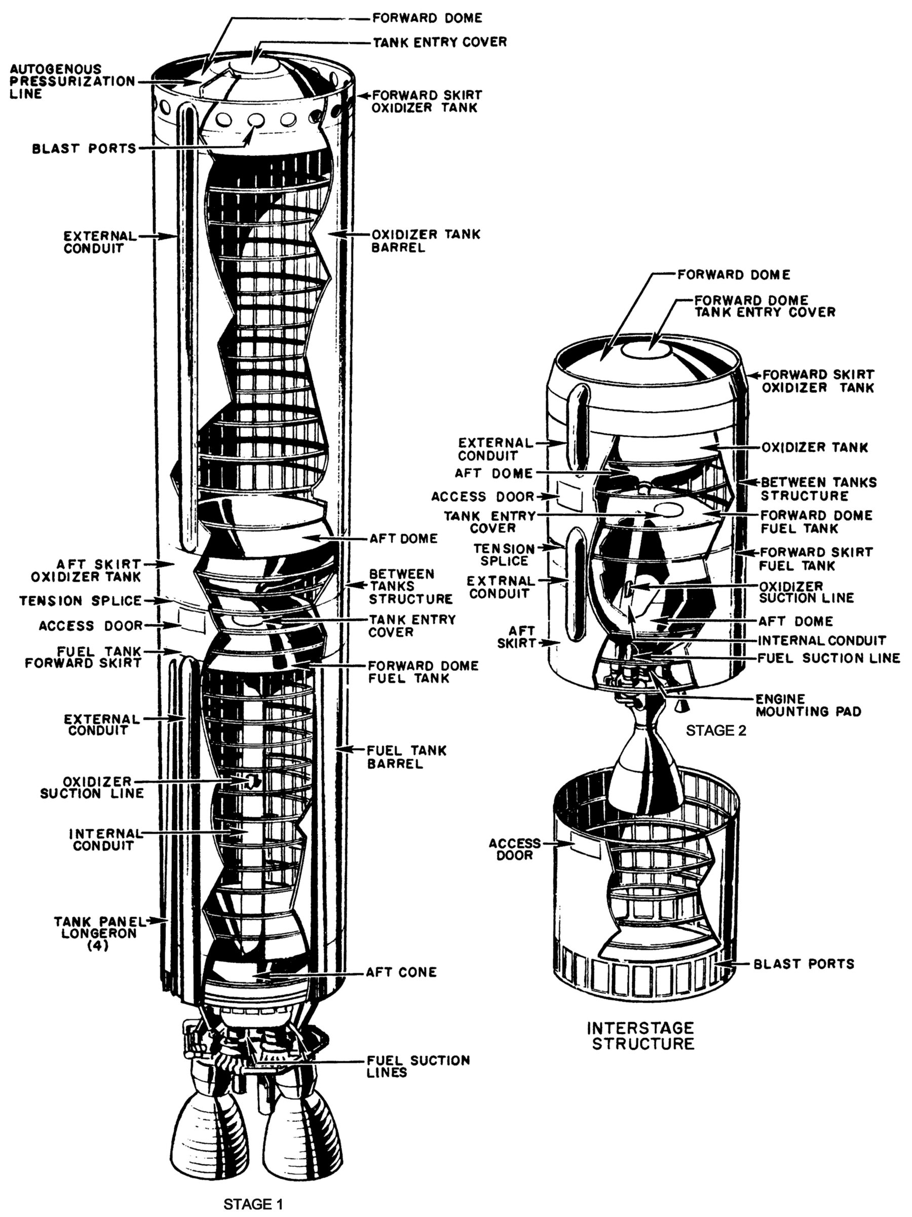
GLV used the same "fire-in-the-hole" staging that Titan II had used; the Stage 2 engine ignited before the stages separated. Exhaust ports in Stage 1 and the interstage adapter vented gasses until staging was complete. Although the propellant tanks were an integral part of the structure, they did not depend on internal pressurization to maintain their shape. All tanks were welded aluminum alloy bolted to short cylindrical sections between the tanks. Vertical wiring runs were housed in external conduits.
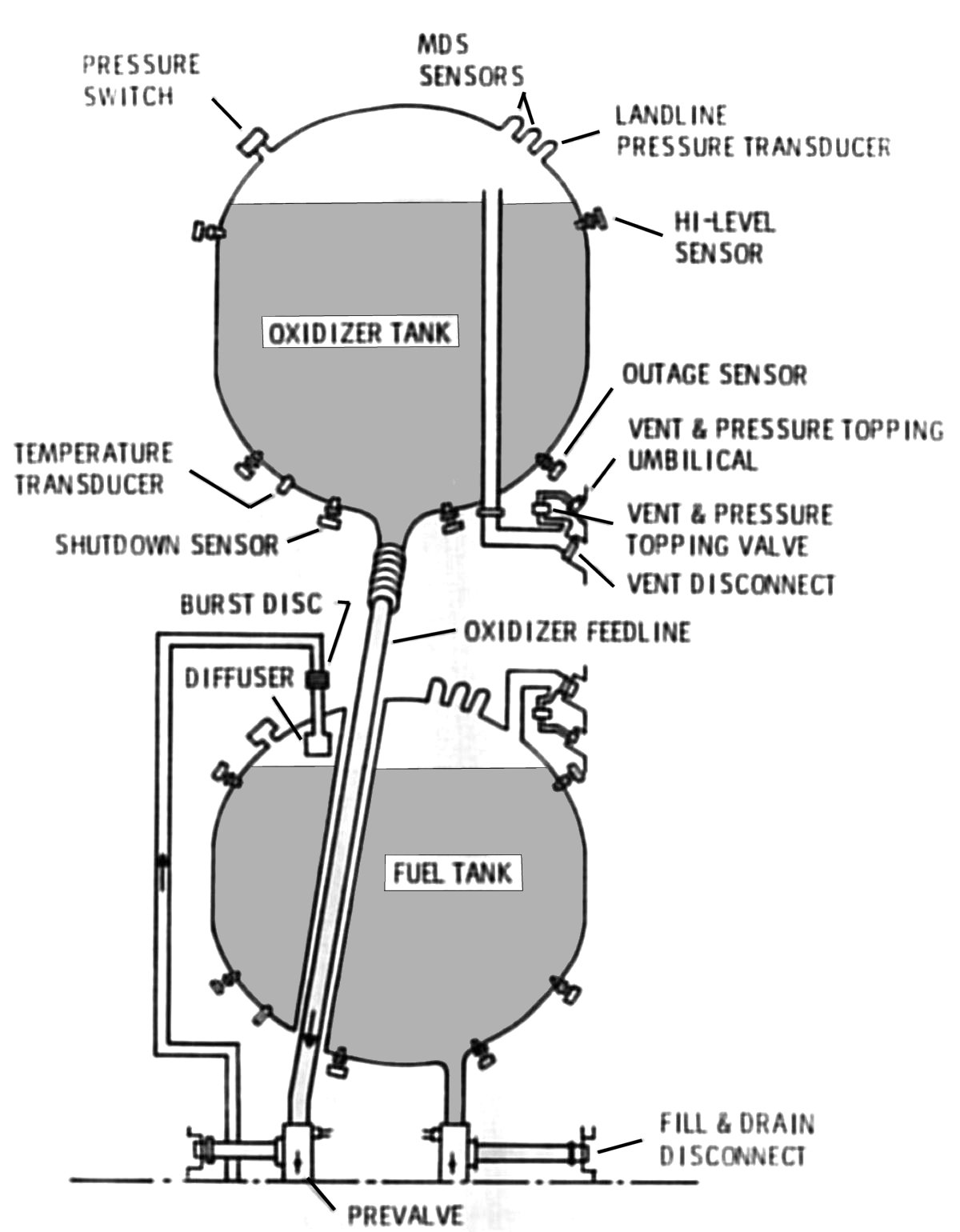
Both stages used Aerozine 50 for fuel and nitrogen tetroxide as an oxidizer. Stage 1's oxidizer feed line was a 10" aluminum tube that passed through the fuel tank and then divided into two 7" lines, one for each engine. Stage 2 had a 6" oxidizer feed line that passed through its fuel tank. A portion of the hot turbopump exhaust was cooled and supplied head pressure to each stage's fuel tanks. Vaporized oxidizer generated by a Stage 1 engine heat exchanger was used to pressurize the Stage 1 oxidizer tank. The Stage 2 oxidizer tank did not require pressurization.
Guidance during Stage 2 flight was achieved via a GE/Burroughs Mod II G radio guidance system, which provided final corrections necessary to achieve the exact orbit required. A combination of ground and flight equipment determined the vehicle's position and direction, a ground-based computer calculated corrections, and pitch and yaw commands were radioed from the ground to the vehicle. The guidance system was also responsible for timely Stage 2 shutdown.
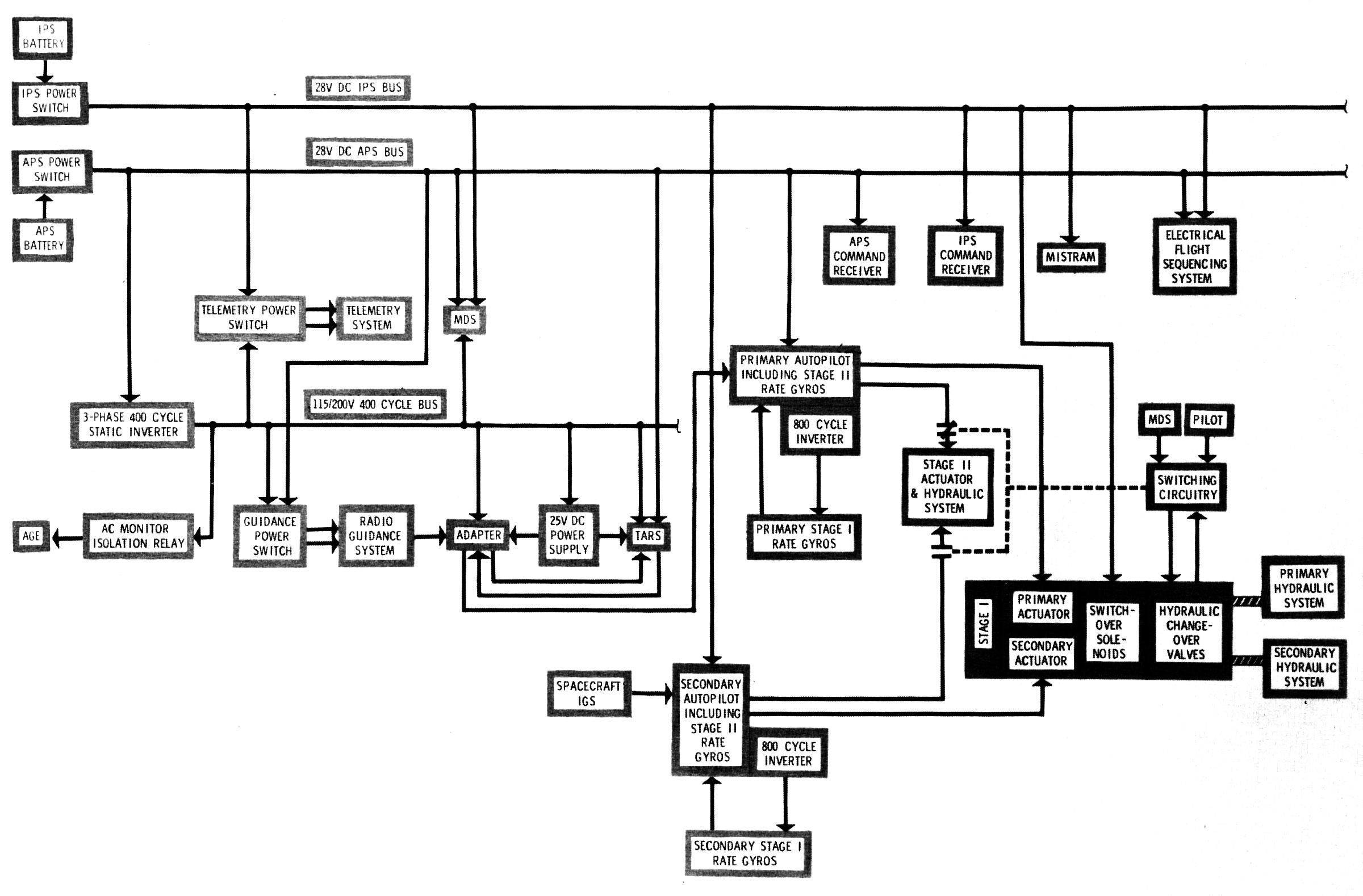
The Flight Control System used gyroscopes to measure rate of change in direction and controlled the trajectory during flight. It maintained the desired azimuth and pitch, executed guidance commands radioed from the ground during Stage 2 flight, and provided timed sequencing for flight events. The flight control system was completely redundant, using the spacecraft inertial guidance system as a backup to the radio guidance system. The secondary system became active when the pilot commanded it, when a malfunction was detected, or if Stage 1 primary hydraulic pressure was lost.
Redundant Stage 1 and Stage 2 hydraulic systems, controlled by electrical signals from the flight control system, commanded engine thrust chamber position through the use of hydraulic actuators. This changed the thrust vectors and vehicle attitude.
The redundant Electrical System, supplied by two 28 VDC batteries, included a time sequencing scheme that controlled things like Stage 1 shutdown, firing of stage separation nuts and Stage 2 engine starting.
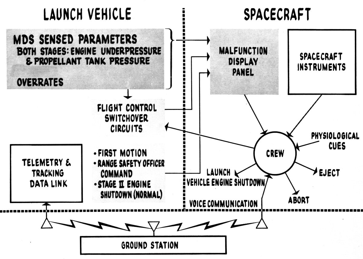
A Malfunction Detection System (MDS) was a significant addition required to human-rate the Titan II for the Gemini program. The MDS monitored vital launch vehicle subsystems and signaled the crew if a malfunction occurred; it was up to the crew to abort the mission. However the MDS automatically switched to secondary systems if sensors detected high turning rates, low hydraulic pressure, and engine hard-over condition.
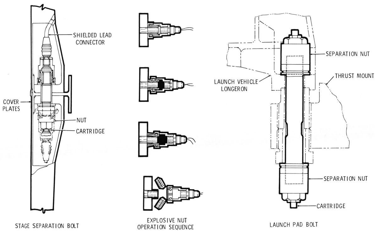
Separation Systems released the launch vehicle from the launch pad and Stage 2 from Stage 1. In each case four sets of explosive nuts held the components together. A stud passed through the attachment flanges and an explosive nut was tightened onto both ends of the stud. An electrical signal caused both nuts to explode, thereby releasing the stud and the components it held together.
A Range Safety and Destruct System employed a General Electric Missile Tracking and Measurement System that provided the range safety officer with accurate range, rate, velocity and trajectory information. If the officer decided to terminate a flight an abort warning was sent to the launch vehicle to shut down the engines and notify the crew. After a short delay a second command ignited pyrotechnic charges that punctured the domes in adjacent fuel and oxidizer tanks, allowing the hypergolic propellants to mix and destroy the vehicle. Presumably the crew, having been warned of the launch vehicle's destruction, would have initiated either ejection or capsule separation, depending on the vehicle's altitude.
A Redundant Stage 2 Shutdown system ensured precise orbit insertion speed. This consisted of an electrically-operated squib valve that immediately shut down the gas generator oxidizer supply upon activation. This led to immediate Stage 2 engine shutdown.
Retro and vernier rockets that had been used to steer the Titan II Stage 2 and reentry vehicle were removed.
In order to ensure the high reliability required for human rating, engineers decided to change as little as possible and that the changes made would be to enhance overall reliability and safety. In addition, the design and production processes were upgraded to include special component handling procedures, careful selection of qualified personnel, exhaustive launch vehicle checkout and procedures intended to ensure flawless launch vehicle performance. All of this “Zero Defects” quality control effort paid off – twelve GLVs were built and all twelve achieved nearly flawless flights.
 |
 |
 |
 |
| Electrical System | Malfunction Detection System | Stage Separation Hardware | Stage 1 Pogo Suppression Modifications |
 Titan GLV (Wiki) |
 GT-4 Launch (NASA) |
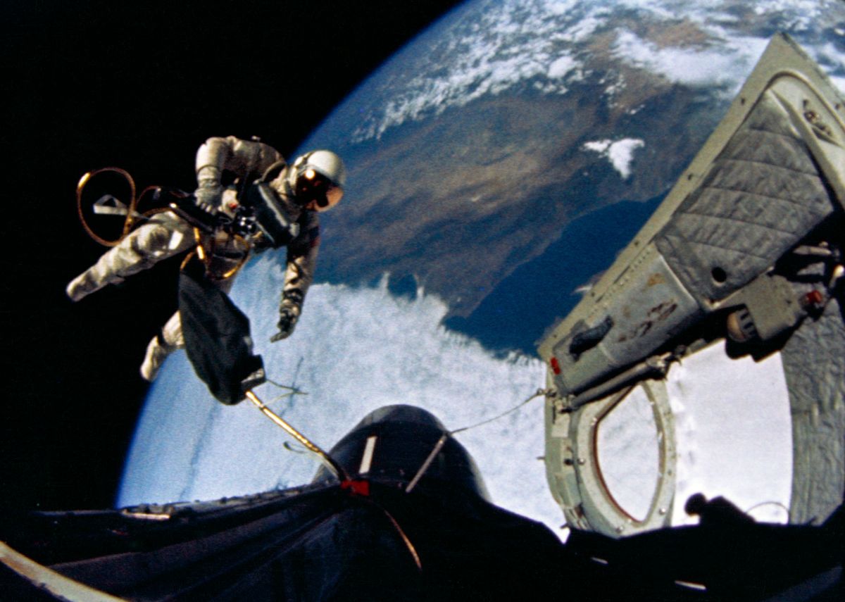 GT-4: First U.S. EVA (NASA) |
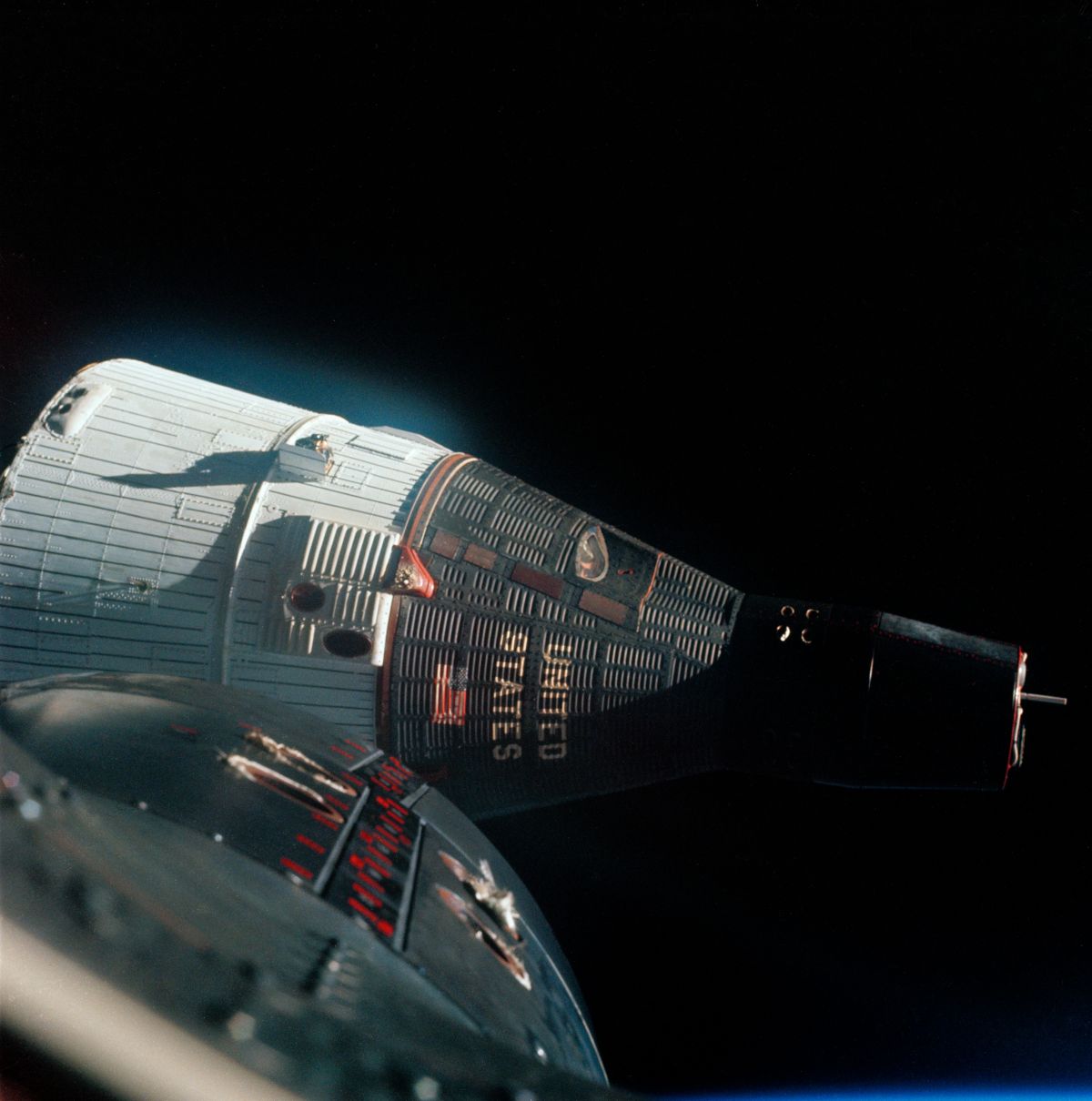 GT-6: First Rendezvous (NASA) |
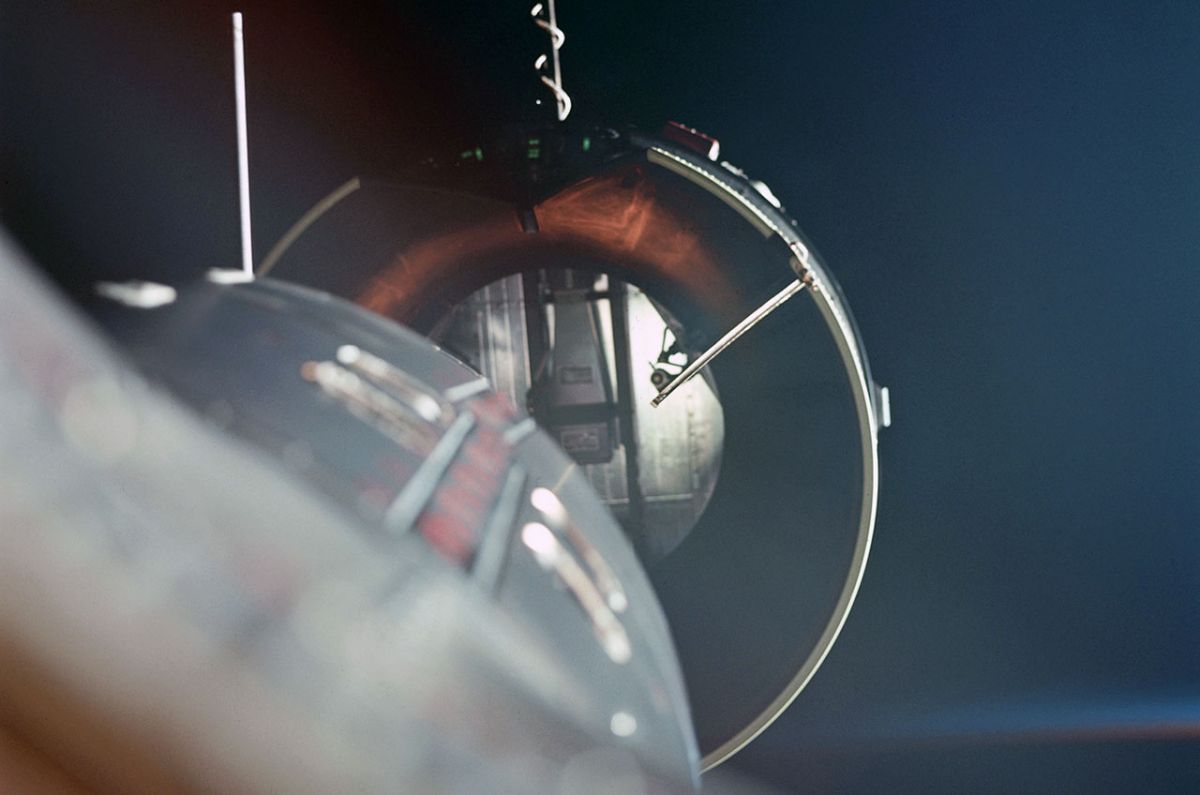 GT-8: First Docking (NASA) |
 GT-12: EVAs Mastered (NASA) |
The Gemini Program
The Gemini Program seems to have been almost lost to history. The U.S.A. had already launched its first astronaut and orbited its first astronaut; the giant Saturn V was under development and, along with the Vietnam War and social unrest, getting most of the press coverage. Despite its lack of fanfare, the Gemini Program’s objectives were monumental and its accomplishments profound. One can only marvel at the ingenuity of its planners, engineers and controllers and be awestruck by the bravery of its crews.
Gemini had five major goals:
These goals involved the development of space suits, EVA procedures, launch logistics, navigation computers, life support equipment, electrical power generation based on fuel cells and many more technologies. Regarding the long-duration missions, one must realize that the Gemini spacecraft had a very small interior volume – only 55 ft³, which had to be shared by two adults. This is not even twice the Mercury spacecraft’s 36 ft³; by comparison, the Apollo Command Module was absolutely palatial at 216 ft³. When one stands beside a Gemini spacecraft and looks inside at the space available for crew, space suits, equipment, food, water, checklists, experiments and garbage, it is inconceivable that two people could survive in such a small space for nearly two weeks.
Gemini-Titan (GT) Mission Summaries (all times Eastern Time)
The Gemini program lasted a short three and a half years, but by the time it was complete, Americans had learned all the skills necessary to go to the moon. [Gemini-Titan II Press Handbook)]
Titan I Propulsion
LR87-AJ-1 and LR87-AJ-3
Early LR87-AJ-1 and later LR87-AJ-3 engines, burning RP-1 and LOX, provided Titan I Stage 1 propulsion. Two nearly identical engine assemblies were gimbal-mounted to a tubular steel engine frame that bolted to the missile structure. Hydraulic systems responding to flight control system commands managed the thrust vector of each engine, which determined the missile’s attitude and direction. Each engine subassembly included a regeneratively-cooled thrust chamber assembly, turbopump assembly, gas generator assembly, and propellant lines and valves. Both engines started and stopped simultaneously. One subassembly carried a helium heat exchanger. The engine thrust chambers, following Edward A. Neu, Jr.’s construction ideas, were built up from thin-wall stainless steel tubing, shaped to the thrust chamber longitudinal profile and brazed together with external structural hoops. A thrust control system maintained constant chamber pressure by throttling gas generator propellant flow. The -3 engines engine version featured changes to reduce parts count, reduce weight and to eliminate -1 design problems. Another -3 improvement was the incorporation of dry-jacket engine starting, which eliminated the need to pre-fill the cooling jacket.
The turbopump assembly in each engine subassembly included a hot gas turbine, propellant pumps and lubrication equipment. Pressurized oil and oil spray in the gear case, in conjunction with a fuel-cooled oil cooler, provided cooling and lubrication for the gears and bearings. The gas generator assembly, which was bolted to the turbine hot-gas inlet, generated hot gases to drive the turbopump assembly. The gas generator included a valve assembly, injector, combustion chamber and dual pyrotechnic igniters.
The helium heat exchanger, installed on the turbine exhaust duct of engine subassembly No. 2, used hot turbine exhaust to heat and expand helium that pressurized the propellant tanks. Helium flowed from the storage spheres in the Stage 1 LOX tank to the heat exchanger, circulated through a tubing coil, evaporated, and flowed back to pressurize both Stage 1 propellant tanks. Hot gases exhausted from the turbopump exhausts added approximately 600 lbT. [Chulick, 19-23, T.O. 21M-HGM25A-1-1]
Operation
Ground-based engine start equipment containing 3,000 psi nitrogen was attached to the missile via umbilicals. Start switch actuation release the pressurized nitrogen to the turbopump turbine and energized the thrust chamber igniters. The high-pressure nitrogen accelerated the propellant pumps, raising fuel and oxidizer pressure. Rising fuel pressure positioned the thrust chamber pressure sequencing valve to the open position, admitting actuation fuel to the actuator. The actuator opened the main fuel valve allowing fuel to fill the thrust chamber cooling jacket. A connecting rod from the fuel valve opened the LOX valve, admitting LOX to the thrust chamber injector. Fuel entered the injector from the thrust chamber cooling jacket. The propellants were sprayed into the combustion chamber via the injector and ignited by the thrust chamber pyrotechnic device placed at the injector’s center.
A position switch on the thrust chamber fuel valve assembly was actuated as the fuel valve opened, providing an electrical signal to open the gas generator valve pilot valve and energize the gas generator igniters. The pilot valve admitted actuation fuel to the actuator, opening the propellant valves. Propellants from the turbopump assembly flowed to the gas generator injector, sprayed into the combustion and ignited.
A gas generator valve assembly position switch was actuated as the valve opened, providing an electrical signal that closed the nitrogen start valve and de-energizing the thrust chamber and gas generator igniter electrical supplies. Hot gases from the gas generator continued to accelerate the turbopump assembly, supplying propellants to the thrust chamber and gas generator. The rising pressure in the combustion chamber ultimately closed the thrust chamber pressure switch to complete the missile release circuit.
Early -1 turbopumps were energized by high-pressure gaseous oxygen (GOX) furnished by ground-based equipment. This scheme required numerous ground interface connections and the GOX plumbing was difficult to purge. A ground-based high-pressure gaseous nitrogen system replaced the GOX system, spinning the turbine fast enough to start pumping propellants. [T.O. 21M-HGM25A-1-1]
 |
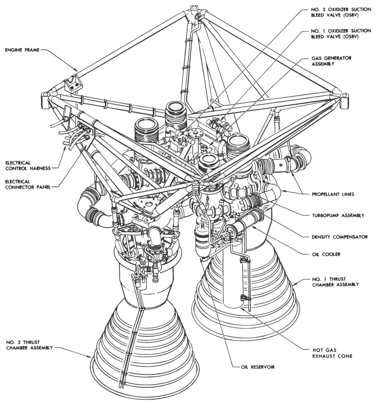 |
LR91-AJ-1 and LR91-AJ-3
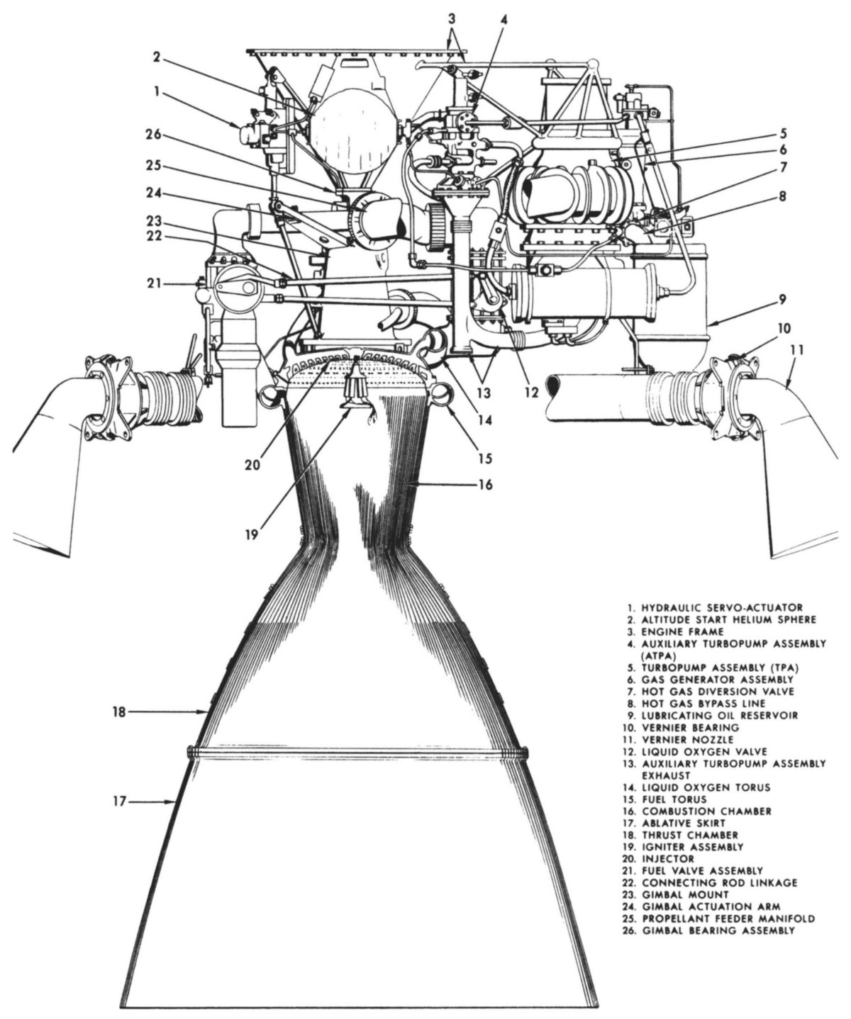
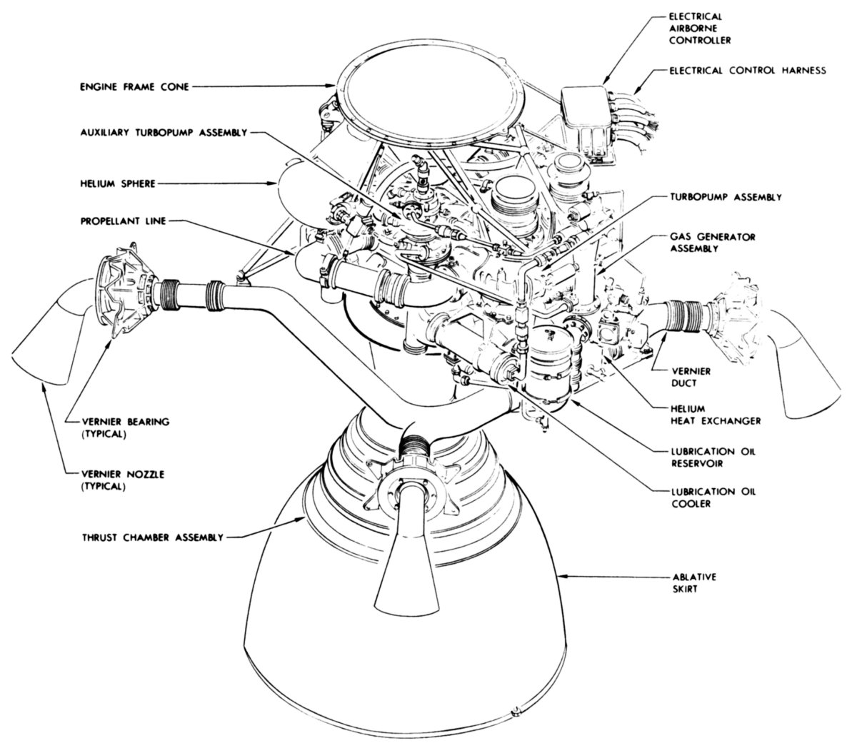
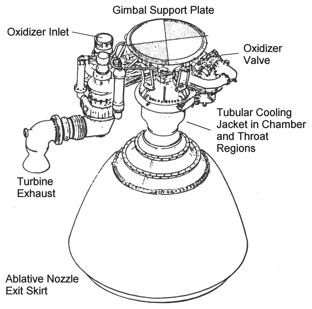
Early LR91-AJ-1 and later LR91-AJ-3 engines, burning RP-1 and LOX, provided Titan I Stage 2 propulsion. A single gimbaled LR91 with a hydraulic actuators responding to flight control system commands that altered the engine’s thrust vector, thereby determining Stage 2’s attitude and direction. Thrust chamber, turbopump and gas generator construction was similar to the LR87, but the LR91 was equipped with an auxiliary turbopump and four gimbaled vernier nozzle. The LR91, operating at altitudes above 250,000 ft, had a much higher expansion ratio (25:1 versus 8:1); this was too much cooling jacket surface area and would have boiled the fuel inside the jacket if the entire nozzle had been devoted to active cooling. To address this, engineers decided to limit the actively-cooled thrust chamber and nozzle portion to a 13:1 expansion ratio. The remainder of the nozzle was a bolt-on ablative nozzle-extending skirt that brought the total expansion ratio up to 25:1.
The -3 engines engine version featured changes to reduce parts count, reduce weight and to eliminate -1 design problems. As with the LR87, the LR91-3 incorporated dry-jacket engine starting, which eliminated the need to pre-fill the cooling jacket. The LR91-3 also replaced the reinforced plastic gaseous helium start bottle with one made from titanium that was less prone to leak.
The LR91 suffered through some development problems. During full-duration runs, coke accumulation on the turbine nozzles, caused by the fuel-rich combustion gas mixture, occluded up to 20% of the nozzle area. The engine control system tried to compensate, but was getting dangerously close to its limits. The problem was cured by introducing a turbulence-inducing swirler near the turbine manifold entrance. This increased the gas generator gas velocity, improved mixing and eliminated the coking problem.
The LR91-AJ-3 operated after stage separation, accelerating the missile along a programmed trajectory. The verniers provided attitude control during stage separation, roll control during Stage 2 engine operation, and final trimming of missile velocity and attitude after Stage 2 engine shutdown.
The LR91-AJ-3 engine included a thrust chamber, turbopump, gas generator, hot-gas diversion valve, auxiliary turbopump, vernier components, helium heat exchanger, propellant lines, altitude start components, an airborne controller, and an electrical harness. The engine frame was an inverted stainless steel cone and a welded steel tube structure. The cone base was attached to the LOX tank support structure and the cone apex was attached via a gimbal bearing to the thrust chamber assembly. The welded steel structure supported the turbopump and auxiliary turbopump. Removable rods supported the vernier ducts and propellant lines.
The engine assembly thrust chamber was gimbal-mounted allowing thrust vector to provide Stage 2 pitch and yaw control. The major thrust chamber components include a combustion chamber and ablative skirt, an injector, propellant valves, a gimbal assembly, a gimbal manifold and swivel assembly, and an igniter assembly.
The turbopump, consisting of a hot-gas turbine, propellant pumps and lubrication system, supplied propellants to the thrust chamber at flow rates required to develop rated thrust. A gas generator, consisting of a combustion chamber, injector, propellant valves, and igniters, burned a mixture of RP-1 and LOX to produce hot gases for the turbopump, auxiliary turbopump, vernier components, and a helium heat exchanger. The diversion valve, a three-way poppet valve located at the gas generator outlet, switched between vernier solo phase and thrust chamber phase during Stage 2 engine operation; it directed hot gas to the turbopump during thrust chamber operation, and bypassed hot gases through the hot-gas bypass line to the helium heat exchanger during vernier solo operation.
The auxiliary turbopump supplied the gas generator with propellants. It includes single-stage centrifugal RP-1 and LOX pumps, and a hot-gas single-stage turbine with one rotor and two gas inlets, all mounted on a common shaft. The fuel pump housing formed the assembly main body and included mounting pads, bearing supports, and internal bearing lubrication passages.
Vernier components included four nozzles, four bearings, and stainless steel hot-gas ducts. The nozzles were placed 90° apart on the outside of the Stage 2 engine compartment; they are controlled by four hydraulic actuators. The nozzles were fastened to the engine compartment framework by bearings that allowed a hydraulic servo-actuator to rotate each nozzle through an arc of 140°. The hot-gas ducts conduct hot gases from the helium heat exchanger to the nozzles. During thrust chamber operation, the hot-gas is used after it is exhausted from the turbopump and auxiliary turbopump assemblies into the helium heat exchanger. During vernier solo operation, the hot-gas from the gas generator passes through the bypass line to the helium heat exchanger.
The helium heat exchanger, installed in the turbopump turbine exhaust duct, used hot gases exhausted from the turbine or directly from the gas generator to heat the helium used for propellant tank pressurization.
 |
 |
Operation
LR91-AJ-3 start components included a spherical 3,000 psi helium start bottle with a solenoid-operated start valve installed at its outlet. A line routed helium from the start valve to the auxiliary turbopump turbine inlet. An electrical signal opened the altitude start valve at the same time that the gas generator pilot valve was opened and the gas generator igniters were energized. Once hot gases from the generator sustained auxiliary turbopump operation the start valve was closed.
An engine controller mounted on the engine frame behind the turbopump received electrical signals from the guidance and control system, which it used to sequence and control Stage 2 engine operation. The engine controller started the gas generator about 7 seconds prior to Stage 1 shutdown by supplying the start signals that opened the altitude start valve and gas generator pilot valve, and energized the gas generator igniters. Pressurized helium accelerated the auxiliary turbopump turbine, which pressurized the propellants causing them to spray into the gas generator combustion chamber, where they were ignited. The hot gases were by-passed the hot-gas diversion valve directly into the helium heat exchanger and exhausted to the vernier. Hot gases were used to sustain operation of the auxiliary turbopump assembly. The verniers operated solo for approximately 4 seconds to provide Stage 2 orientation while stage separation occurred.
Approximately 11 seconds after the gas generator started, the control system generated the thrust chamber-start signal. Hot gases were diverted to the turbopump, causing it to accelerate. Rising fuel pressure opened the thrust chamber propellant valves allowing propellants to reach the thrust chamber injector. During steady-state thrust chamber operation, the verniers provided roll control and the servo-actuators pivoted the thrust chamber to compensate for flight path error detected by the missile guidance system. The thrust control transducer and amplifier assembly controlled the gas generator control valve to maintain constant thrust.
When the shutdown signal was received, the hot-gas diversion valve returned to the bypass position, terminating the turbopump operation. The pilot valve closed and vented actuation fuel, which allowed the propellant valves to close, terminating thrust chamber operation. The gas generator and auxiliary turbopump assembly continued to operate and provide vernier thrust for final missile velocity and orientation trimming.
When the guidance and control system provided the vernier shutdown signal, the gas generator valve pilot valve closed, venting actuation fuel and allowing the gas generator propellant valves to close. This shut down the gas generator, terminated the auxiliary turbopump operation and shut down the Stage 2 rocket engine. [ T.O. 21M-HGM25A-1-1]
If Titan I Stage 1 and Stage 2 engine operation seems extraordinarily complicated it is because it was. A major objective of the Titan II program was to tame this Rube Goldberg creation.
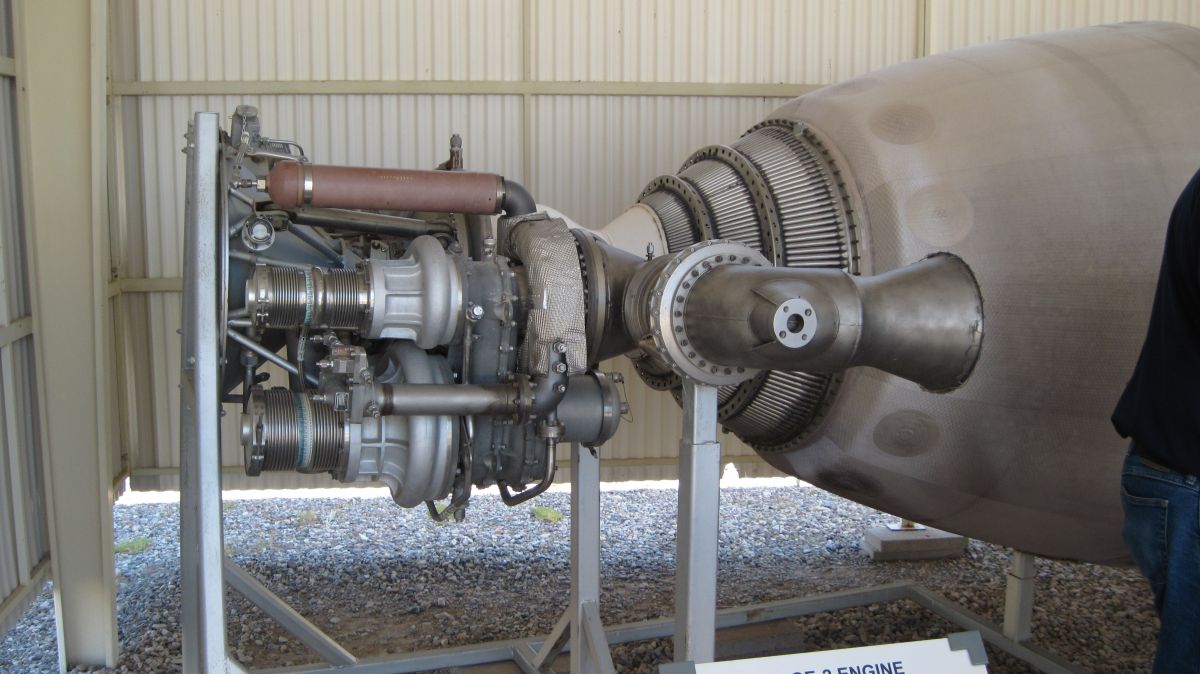
 |
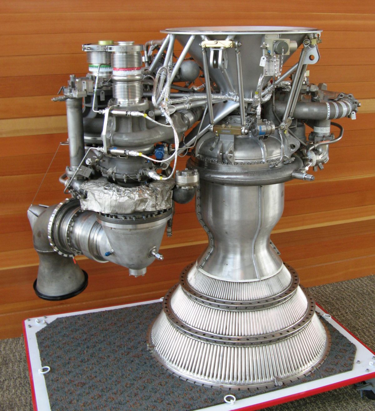 |
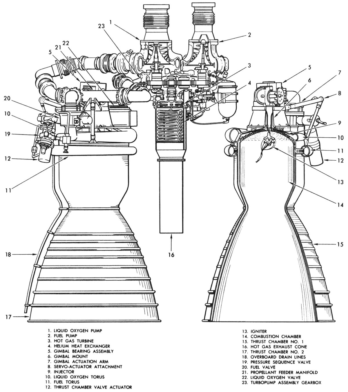
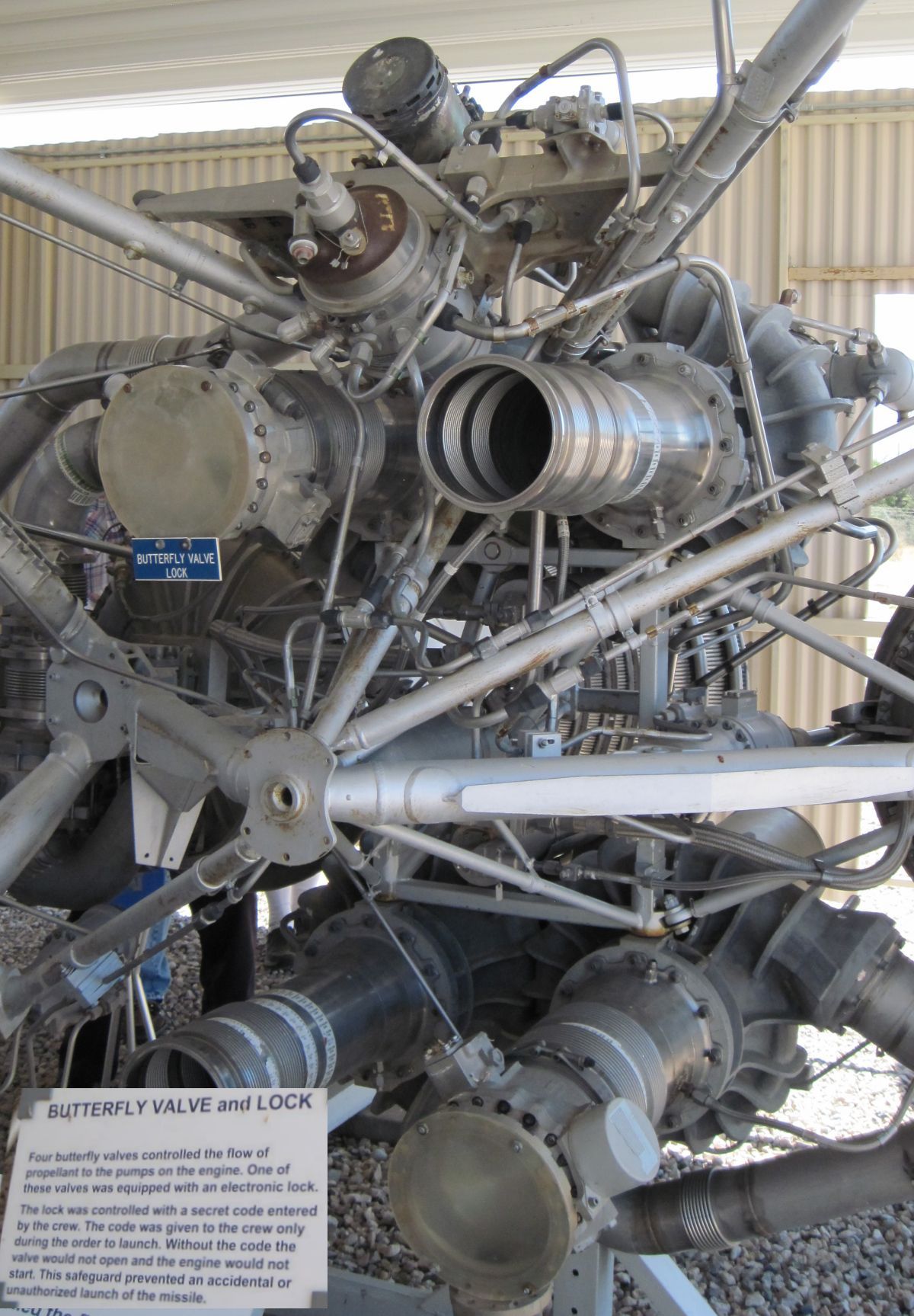
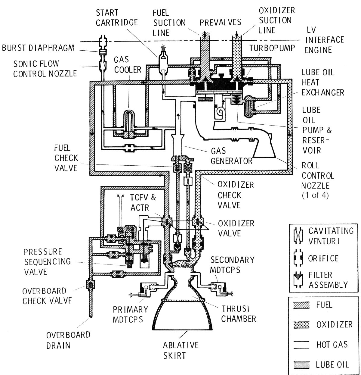
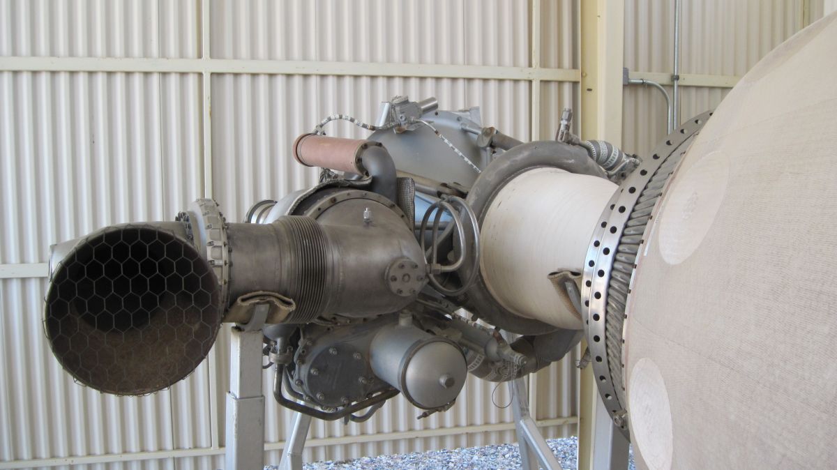
| Compare the complex Titan 1 LR91-AJ-3 Stage 2 engine (left) with the much simpler Titan GLV LR91-AJ-7 Stage 2 engine (right). | |
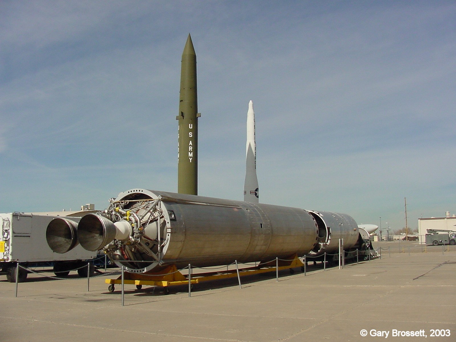
Titan II Propulsion
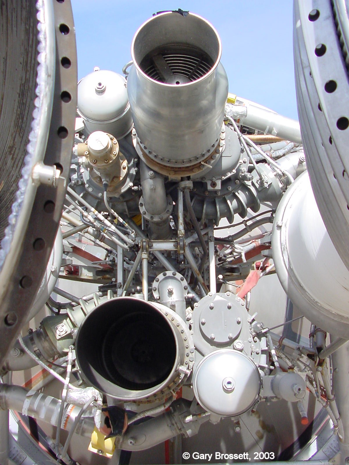
Titan II ICBMs used Aerojet LR87-AJ-5 Stage 1 engines and LR91-AJ-5 Stage 2 engines. Titan GLV used LR87-AJ-7 and LR91-AJ-7 engines for Stage 1 and Stage 2 respectively. The main difference between -5 and -7 engines was the inclusion of a Malfunction Detection System sensors in the -7 engines.
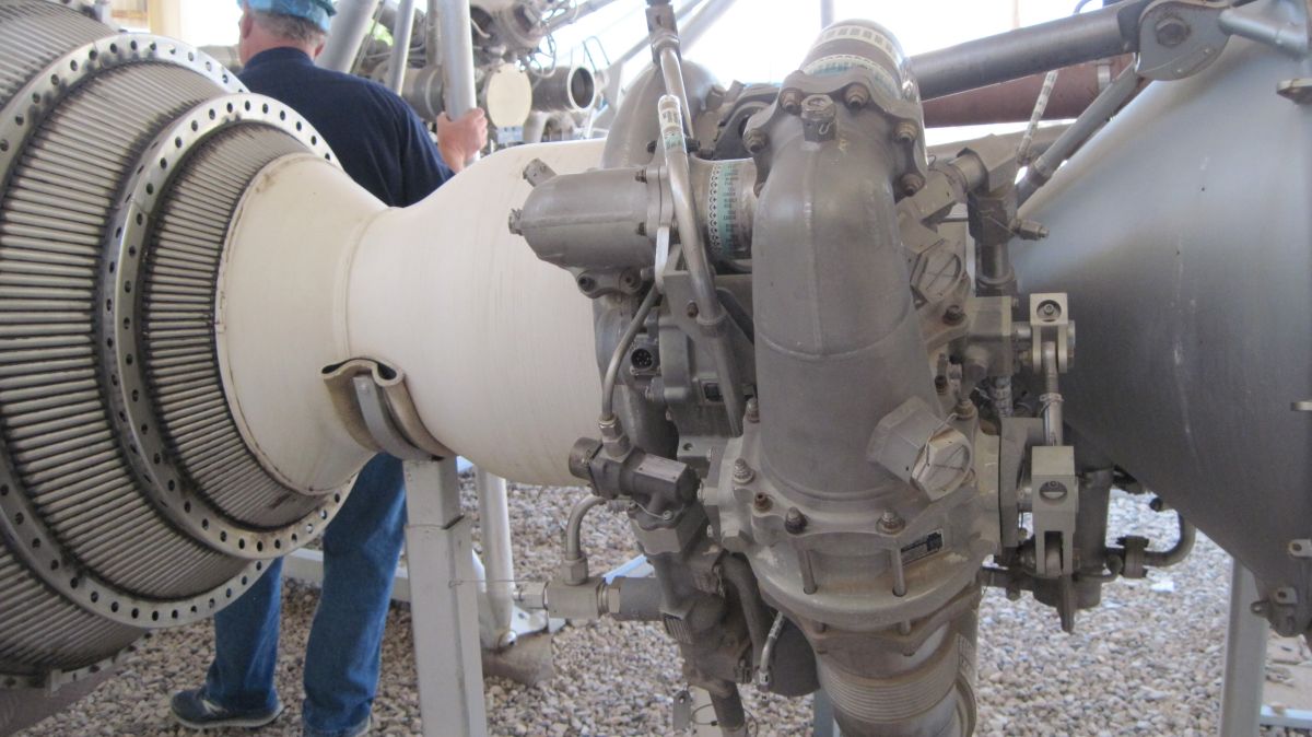
 |
 |
 |
 |
 |
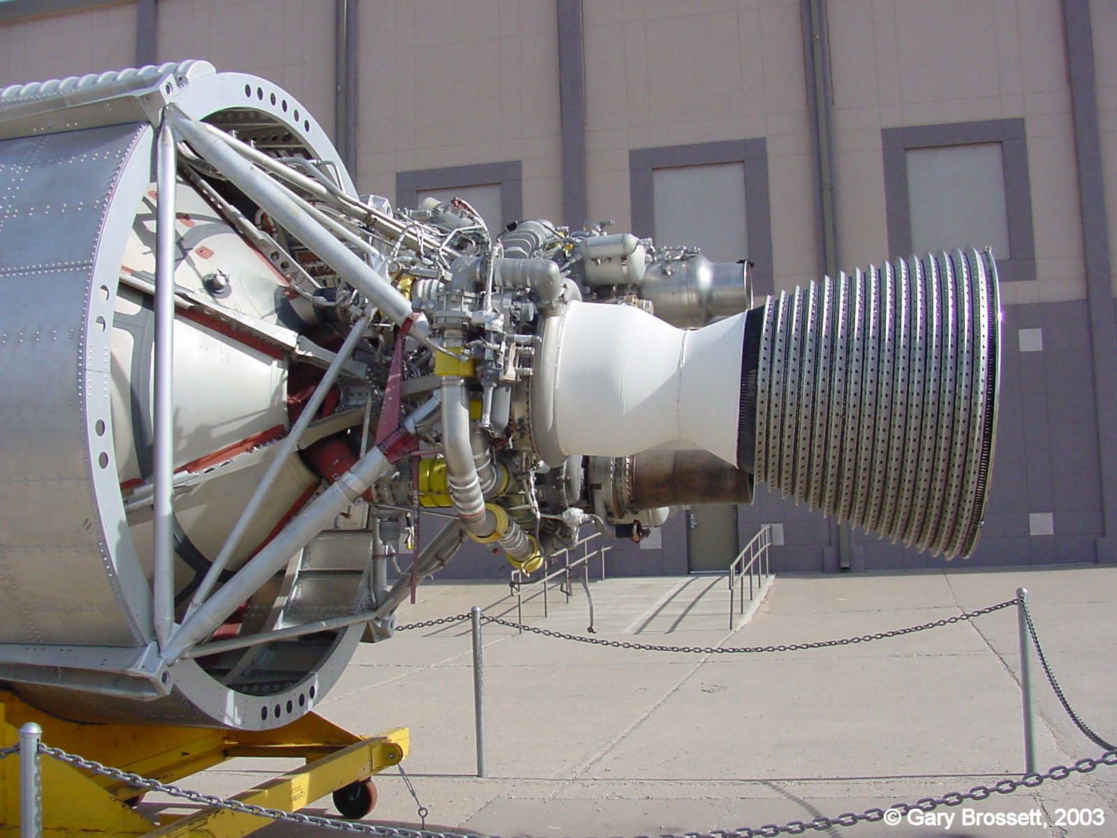 |
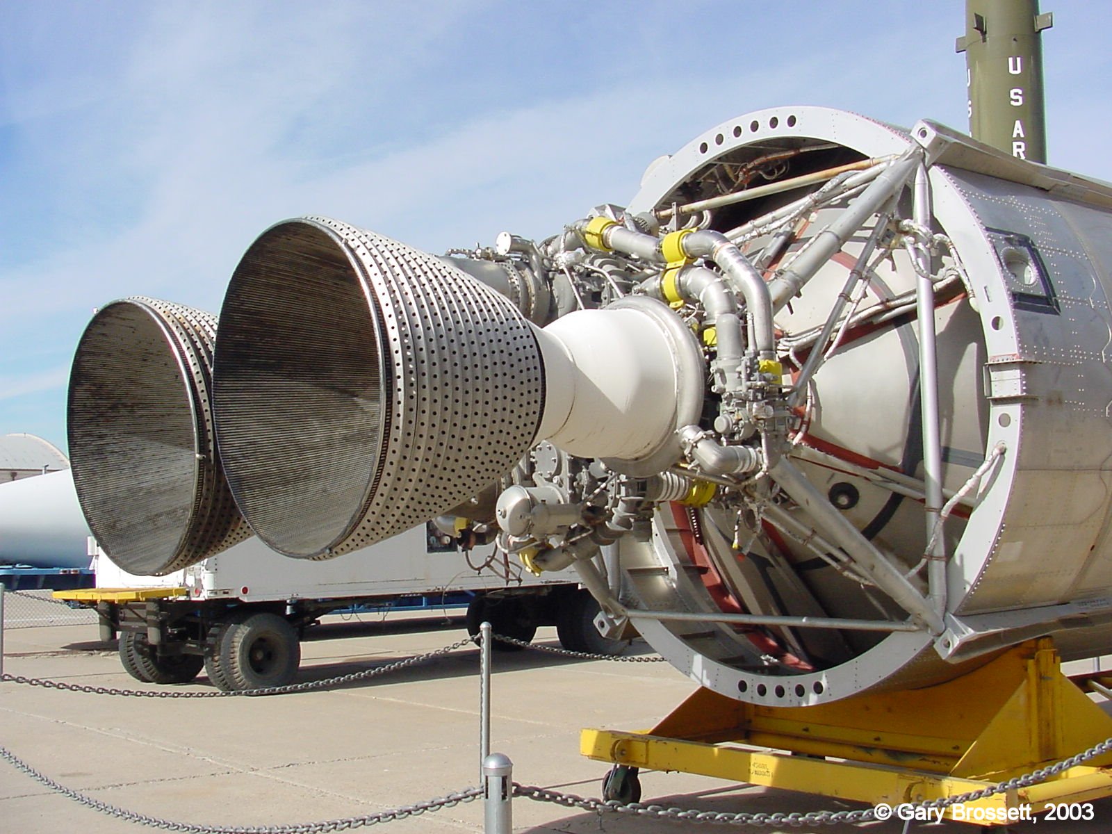
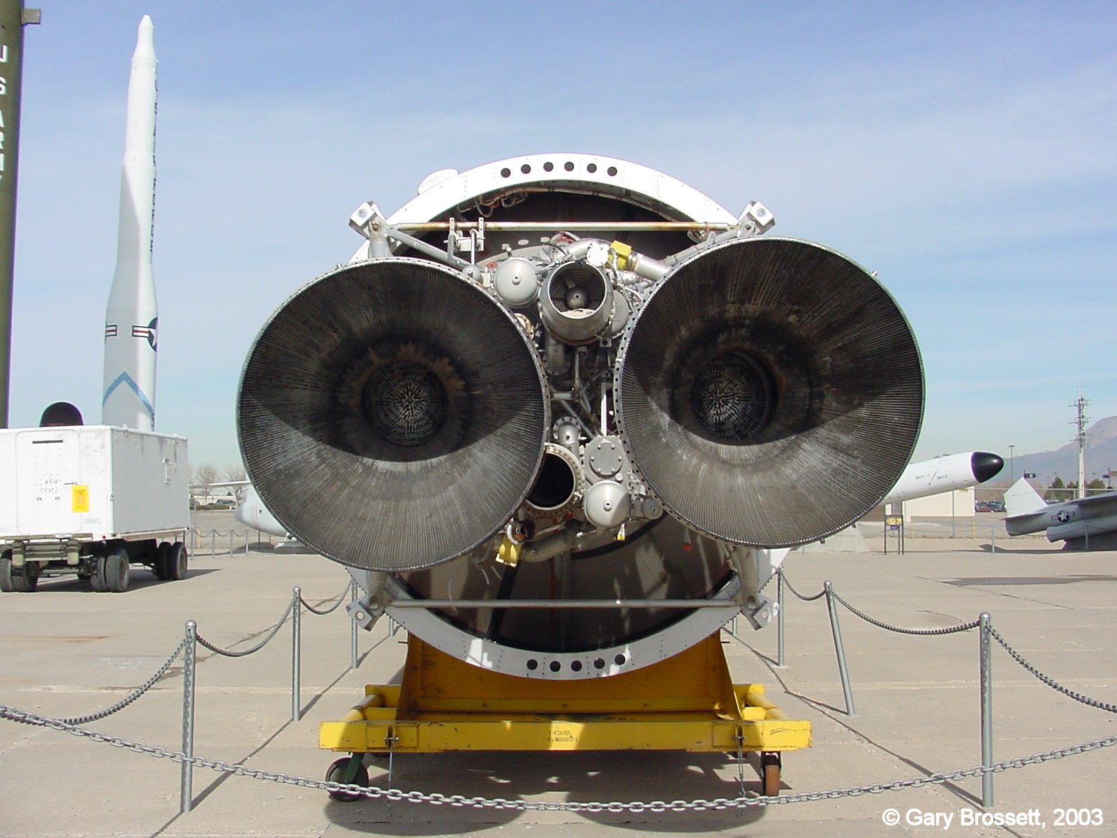
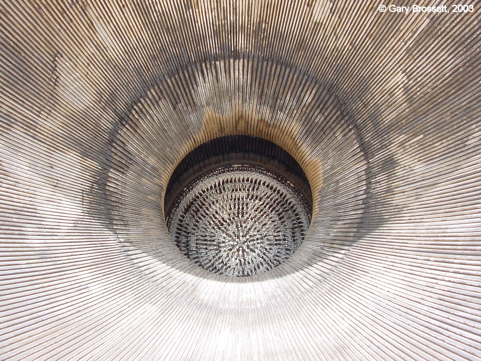
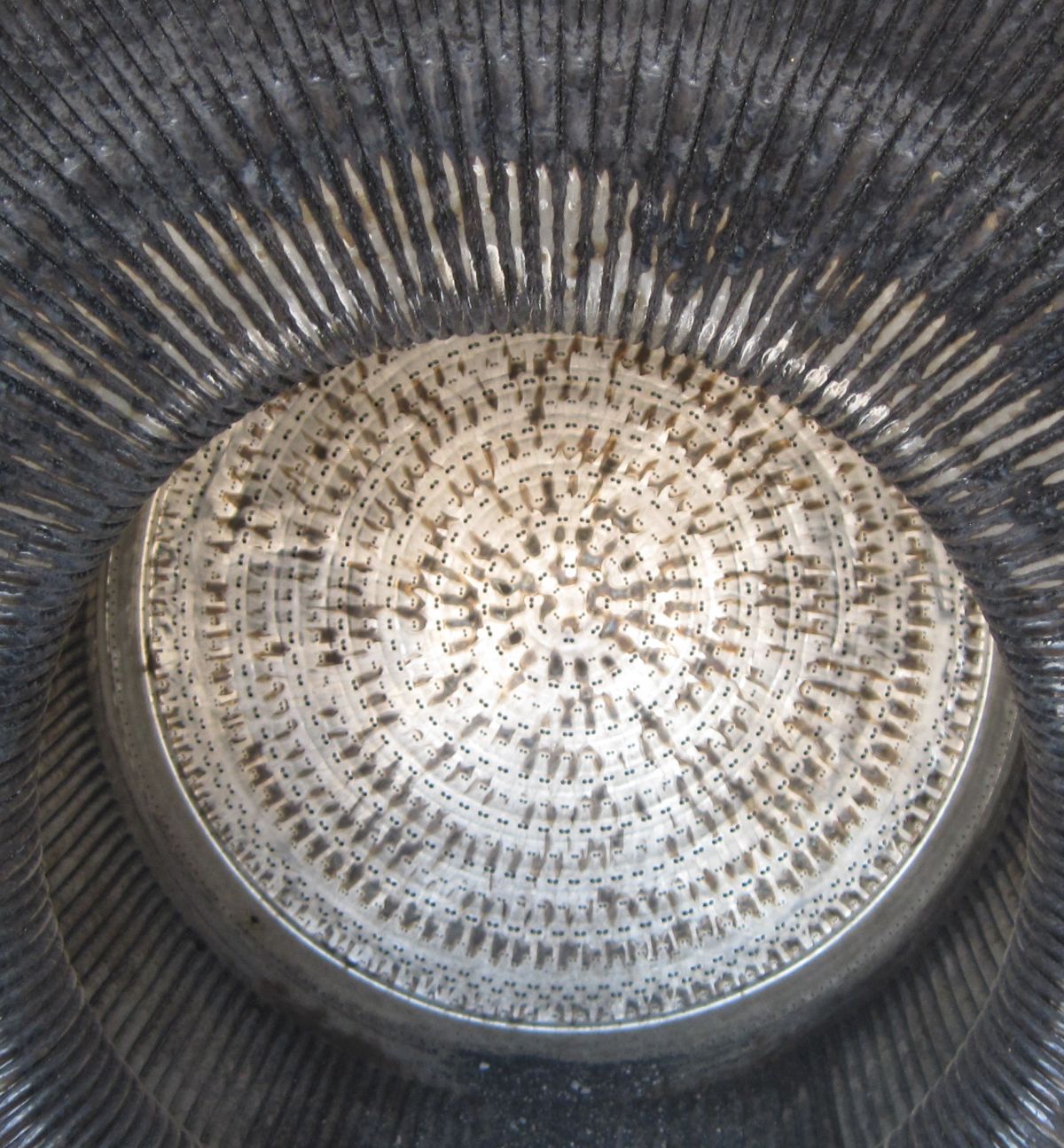
| Blast ports are visible between stages. | Good view of the thrust chamber exterior. | Nozzles and turbopump exhausts. | Oxidizer heat exchanger visible at top. | Injector and thrust chamber throat. | Good view of a fuel valve. |
| Images from the Kirkland Air Force Base by Gary Brossett | |||||
As previously reported, the Graduate Aerospace Laboratories of the California Institute of Technology (GALCIT) and Aerojet began working with storable hypergolic propellants before the U.S. entered WWII. During WWII and the 1950s, Aerojet continued to hone its hypergolic expertise, primarily using aniline for fuel and red fuming nitric acid as an oxidizer. This propellant formed the basis of numerous JATO and sounding rocket designs. Aerojet continued studying propellant combinations and started to find hydrazine (N2H4) to be an attractive fuel candidate, except that it was prone to explode when used to regeneratively cool rocket thrust chambers. A hydrazine derivative, unsymmetrical dimethyl hydrazine (UDMH) (H2NN(CH3)2) seemed to be an attractive alternative, but was in short supply. This changed in 1950 when Karl Klager (15 Mar 1908 – 26 Jan 2002) joined Aerojet. Klager had earned a PhD in Chemistry from the University of Vienna in 1934 and had come to the U.S. as part of Operation Paperclip. Klager figured out how to make large quantities of cheap UDMH and patented the process. Aerojet found a 50-50 mix of hydrazine and UDMH was an ideal blend of performance and utility, and named the fuel concoction Aerozine 50 (A-50). When mixed with the oxidizer dinitrogen tetroxide (N2O4) Aerozine 50 ignited spontaneously. This hypergolic combination formed the basis for Titan II propulsion. The Titan II propulsion system was considerably simpler than that of the Titan 1; active control components were reduced from 125 to 30, while valve and regulator count went from 91 to 16.
Several changes to the Titan I engines helped raise the Titan II Stage 1 engine thrust by 43% and Stage 2 thrust by 26%. Aerojet engineers tinkered with the thrust chamber injector, changing the -3’s like-on-like impingement pattern that to fuel-on-oxidizer impingement using alternating fuel and oxidizer injector rings. This caused injector face erosion, so the impingement pattern returned to like-on-like. Stage 2 engine combustion instability forced the introduction of oxidizer-cooled baffles at the injector. Several different numbers of baffles and baffle material combinations were tried before seven radial copper baffles were selected. Titan II injectors were simplified by replacing a milled solid forging with formed plates that were welded together. Titan I had used both fuel and oxidizer manifolds; Titan II went with a simplified oxidizer dome injector feed.
Although the Titan II turbopumps were similar to Titan I turbopumps, propellant density and higher flow rates required new pumps to handle more power at a lower shaft speed. This also meant the drive gears had to be wider. Impellers were re-shaped and the number of inducer blades went from two to three. The two-stage turbine rotated at 23,000 rpm, the fuel impeller at 8,850 rpm and the oxidizer impeller at 8,000 rpm. A 25 hp hydraulic pump was driven at 3,800 rpm by an accessory drive train. Gear train gears and bearings were lubricated by pressurized oil pumped and scavenged by a five-element (one pressure, four scavenge) oil pump. The pressurized oil from an 8 lb oil supply was directed by jets into the opening gear meshes and into the bearings. A fuel-cooled oil cooler removed heat generated by the gear train and bearings.
New impeller shapes forced housing redesigns. The two impellers rotated in opposite directions to minimize gyroscopic effects. New seal and gasket materials were introduced to handle the highly reactive new propellants. The gaseous high-pressure nitrogen and helium starting systems were replaced by solid propellant start cartridges that initially got the turbines spinning.
Titan II replaced the complicated propellant tank pressurization scheme used on Titan I. The new fuel tank pressurization system tapped hot gas from the gas generator, ran it through a cooler, then a sonic nozzle and finally to the propellant tank. This new method had no moving parts or delicate controls. The Stage 1 oxidizer tank was pressurized by N2O2 vapor generated by a heat exchanger in the turbopump exhaust. The Stage 2 oxidizer tank did not require pressurization.[ Hunley, 164-165; Chulick, 26-27]
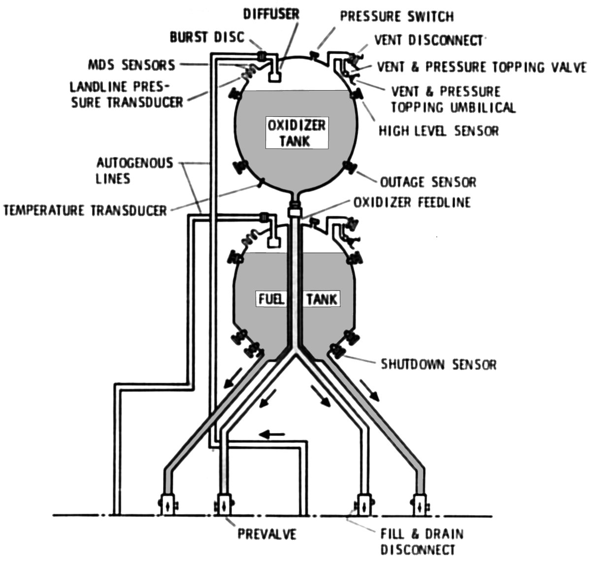
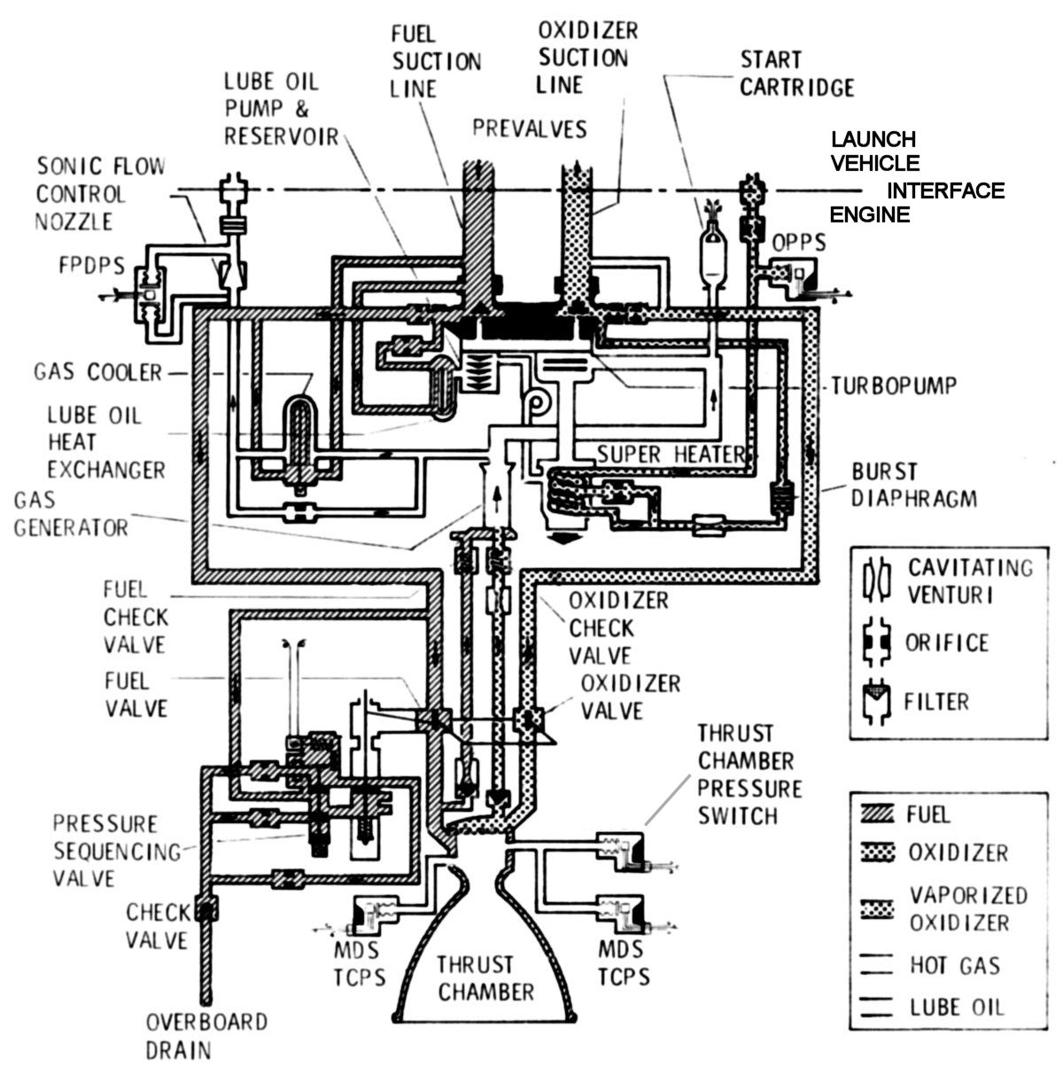
Stage 1 Propulsion
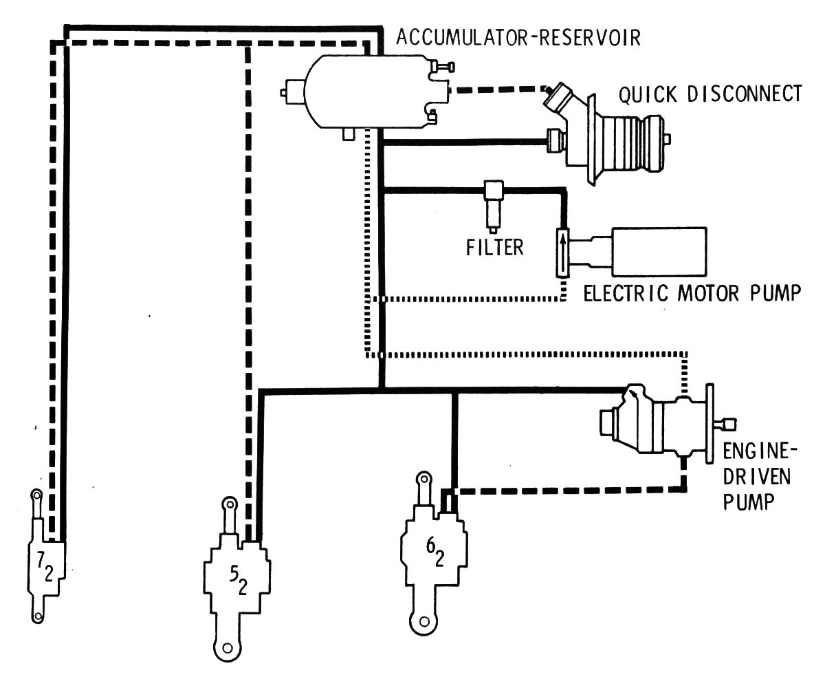
Two nearly identical engine subassemblies comprising the Aerojet LR87-AJ-5 and -7 were mounted via gimbal bearings to a steel engine frame. The gimbals allowed each thrust chamber to independently swivel 5° from neutral in any direction. The thrust chambers were each controlled by two hydraulic actuators attached to the thrust chamber and the engine frame. The actuators responded to electrical signals from the missile guidance and control system. Hydraulic pumps mounted on the engine turbopump assemblies provided hydraulic pressure to the actuators. In the Titan GLV a redundant set of hydraulic actuators powered by an electrically-driven hydraulic pump could take over thrust vector control if the primary engine-driven system failed. Flexible fuel and oxidizer supply duct sections allowed the thrust chambers to move while the turbomachinery stayed fixed. This scheme allowed roll, pitch and yaw control of the missile.
 |
 |
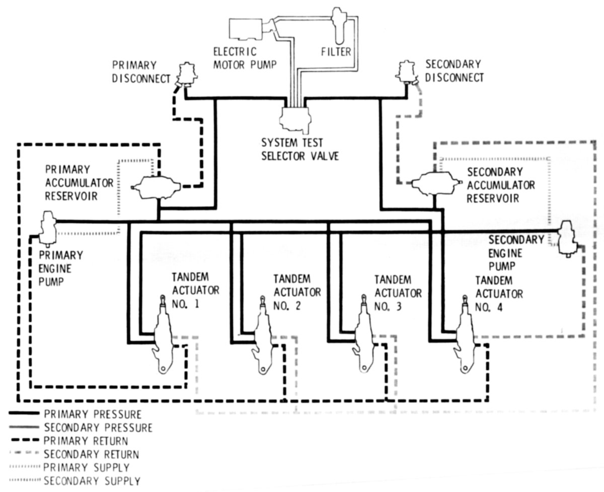 |
| Titan GLV Stage 1 Propellant System | Titan GLV LR87-AJ-7 Engine Subassembly Schematic | Titan GLV Stage 1 Hydraulic System |
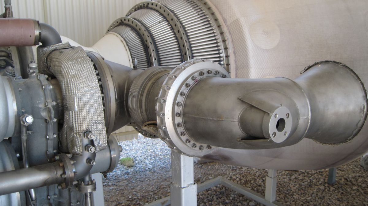
 |
 |
 |
 |
 |
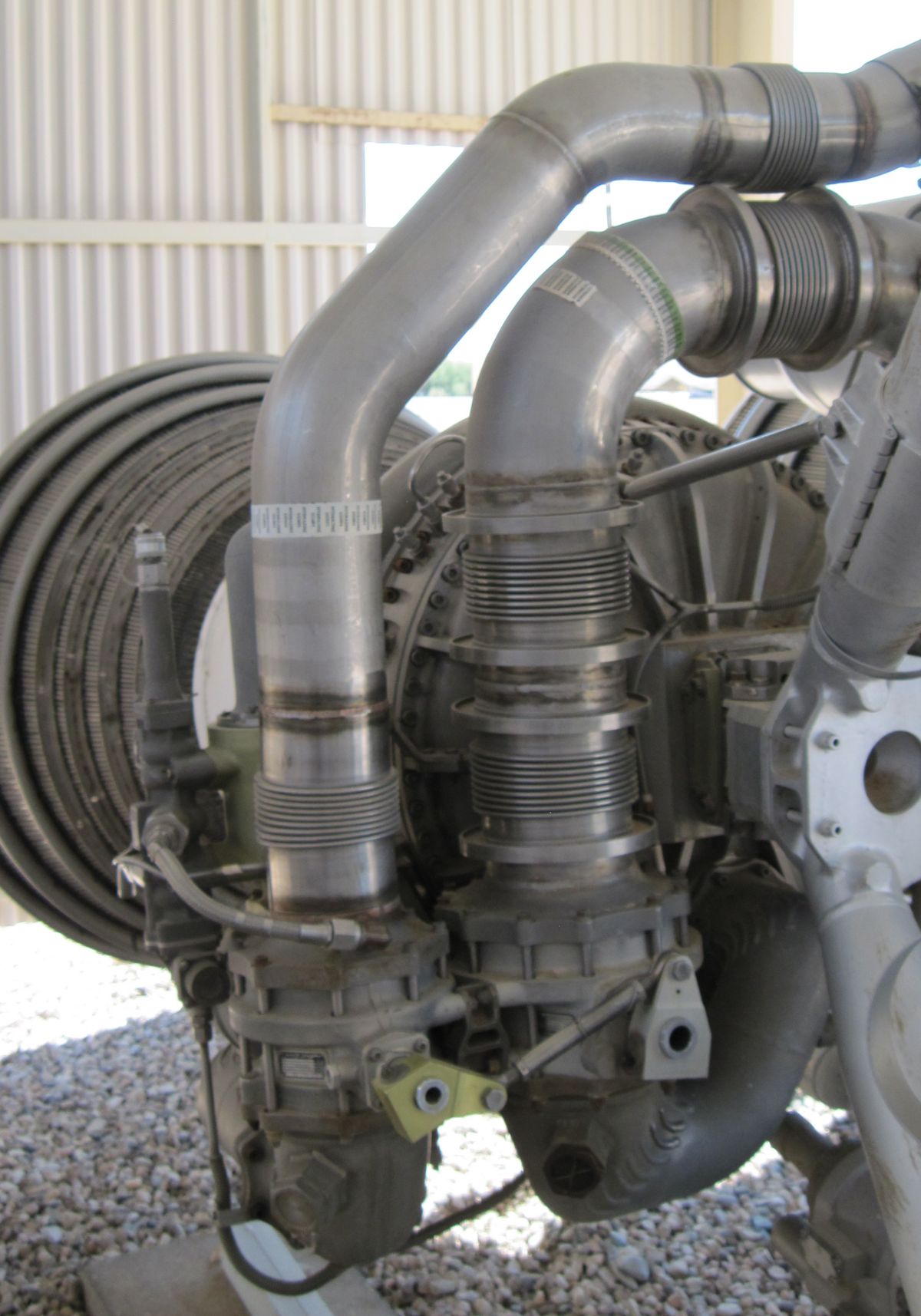 |
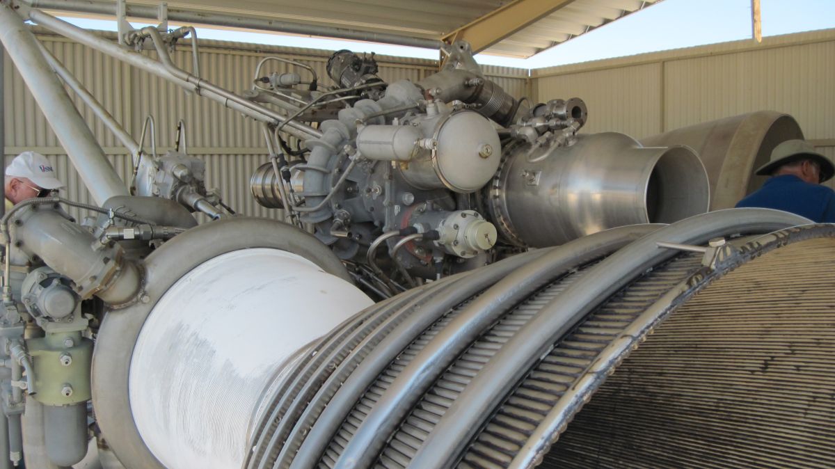
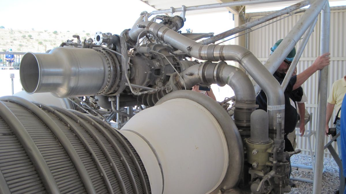
| Overall View | Turbopump, Oil Reservoir, Oil Cooler, Hydraulic Pump | Turbopump, Flexible Ducts | Injector and Nozzle Throat | Engine Top, Propellant Connections | Flexible Ducts, Fuel Valves |
Operation
Both engine subassemblies were started and stopped simultaneously. If the control system detected a problem with either engine subassembly at any time, it would shut down both subassemblies.
An arming signal from ground control armed the start cartridge squib circuit and caused fuel and oxidizer prevalves to open, admitting propellant to the turbopump suction lines. A subsequent firing signal from ground control, a 28 VDC electrical signal activated the solid propellant start cartridge, which introduced 2,000 psia gases to the turbopump turbine and got it spinning. If one watches videos of Titan II launches, one can hear a "whoop" just before ignition; this sound is the start cartridge spinning up the turbine. Once the turbopump started to spin both fuel and oxidizer pressure started to rise. When fuel pressure reached 295 – 325 psia the pressure sequencing valve shuttled to the open position, diverting fuel pressure to the opening side of the thrust chamber valve actuator, which then opened the mechanically-connected thrust chamber fuel and oxidizer valves, admitting propellant to the thrust chamber and gas generator. Once in the thrust chamber, oxidizer flowed into the oxidizer dome, forcing out any air, through the injector face and into the thrust chamber. Fuel flowed through the fuel torus into thrust chamber cooling jacket down tubes to a manifold at the thrust chamber bottom where flow reversed into up tubes, into the injector and finally through the injector face. This fuel flow regeneratively cooled the thrust chamber. Some of the fuel also sprayed against the thrust chamber walls, providing film cooling.
Once in the thrust chamber, fuel and oxidizer ignited on contact. Meanwhile, when propellant pressure in the gas generator propellant supply circuit exceeded the residual pressure from the start cartridge, fuel and oxidizer flowed past the fuel and oxidizer check valves, into the gas generator injector and ignited in the gas generator, taking over the task of keeping the turbopump spinning. Some of this hot gas flowed through a fuel-cooled heat exchanger and was used to pressurize the fuel tank. A hot-gas bypass orifice connected in parallel to the cooler provided temperature control and a sonic nozzle controlled flow to the tank. A fuel pressurization differential pressure switch (FPDPS) provided a signal indicating proper fuel tank pressurization system operation. An oxidizer superheater on the turbopump turbine exhaust evaporated some of the oxidizer to produce gaseous oxidizer that pressurized the oxidizer tank. When oxidizer pressure reached 300 ± 30 psi a burst diaphragm admitted oxidizer through a cavitating venturi to the heater coil. A bypass orifice provided temperature control and an oxidizer pressurization pressure switch (OPPS) provided a signal indicating proper oxidizer tank pressurization system operation. Only one engine subassembly was equipped with the oxygen pressurization system. Both fuel and oxidizer tanks were pressurized to about 6 psi.
During steady-state operation, engine thrust level was held constant through the use of three cavitating venturi tubes in the gas generator propellant supply, which maintained steady turbopump speed and constant propellant flow to the thrust chambers.
Engine shutdown occurred when either the fuel or oxidizer (preferably oxidizer) supply was exhausted. As propellants were depleted a thrust chamber pressure switch (TCPS) sensed thrust chamber pressure decay and opened the 28 VDC circuit supplied by the engine controller. This in turn caused the pressure sequence valve to shuttle back to its original CLOSED position, routing fuel pressure to the thrust chamber valve actuator closing side, thus closing the fuel and oxidizer valve. [Gemini-Titan II Press Handbook]
 |
 |
 |
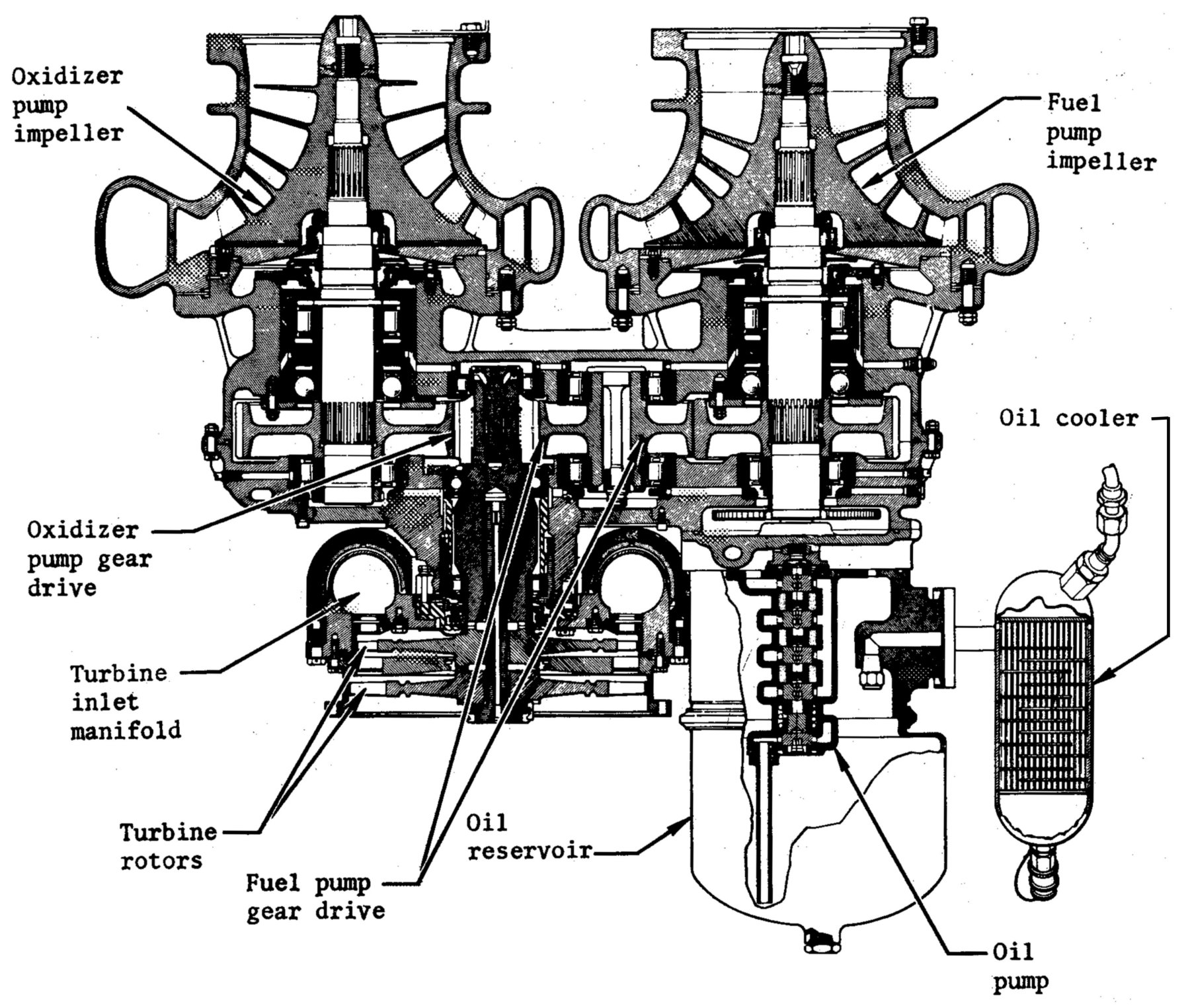
| LR87-AJ-5 (heriocrelics.org) | LR87 Turbopump Longitudinal Section | LR91-AJ-5 (heriocrelics.org) |
Stage 2 Propulsion
LR91-AJ-5 and -7 engines were single thrust chamber engines very similar to LR87-AJ-5 and -7 engine thrust chambers. The thrust chamber was gimbal-mounted and articulated via a dual-redundant hydraulic system through a range of 4° from neutral, allowing pitch and yaw control. LR91 differences included:
 |
 |
 |
| Titan GLV Stage 2 Propellant System | Titan GLV LR91-AJ-7 Engine Subassembly Schematic | Titan GLV Stage 2 Hydraulic System |
 |
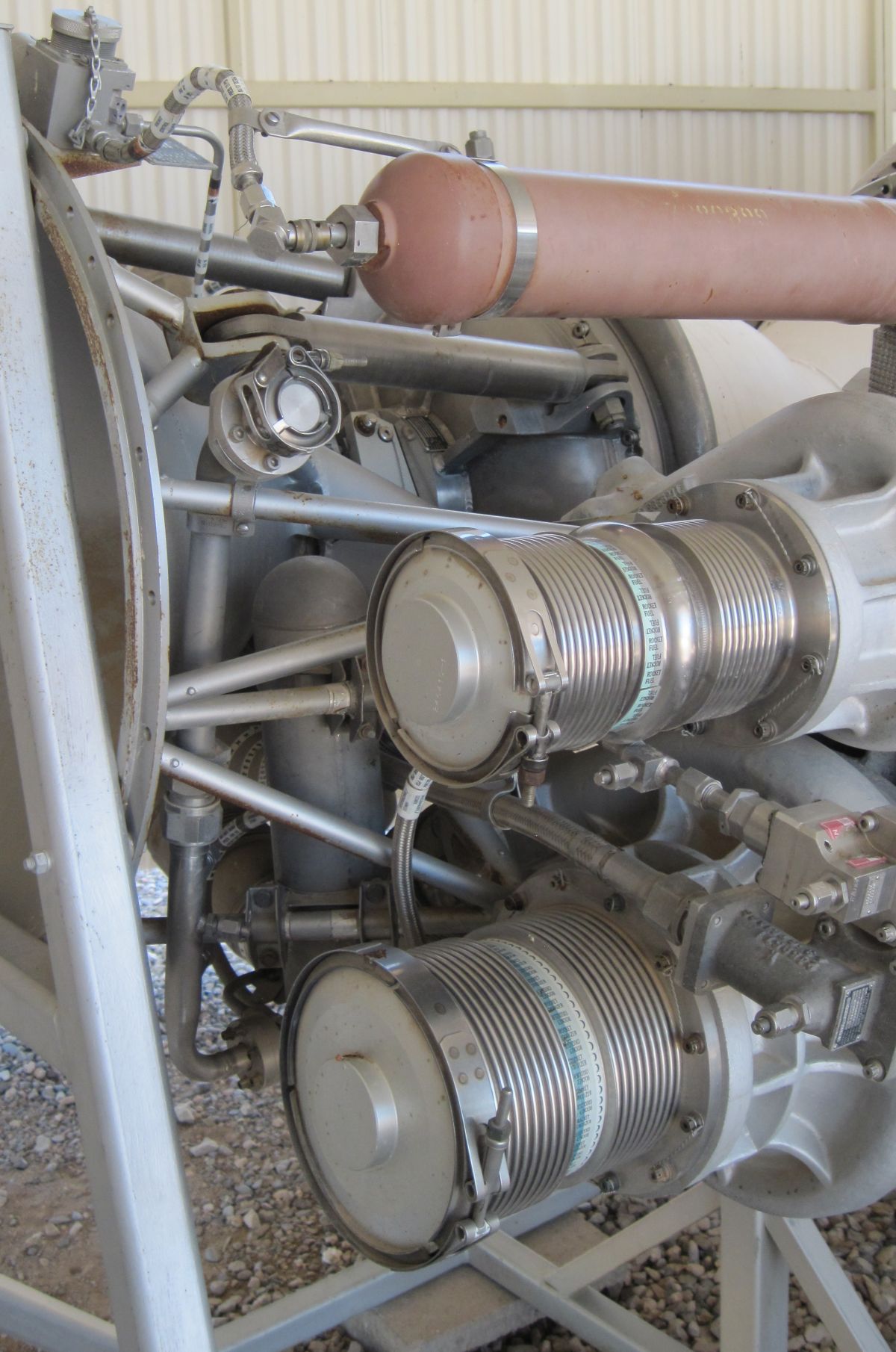 |
 |
 |
 |
| Overall View | Start Cartridge and Propellant Ducts | Turbopump, Roll Control Nozzle | Propellant Valves | Start Cartridge, Turbopump, Roll Control Nozzle, Oil Reservoir |
Operation
The Stage 2 engine began operating slightly before Stage 1 shutdown and provided the force necessary to separate the stages. The Stage 2 firing signal was initiated by the thrust chamber pressure switch during Stage 1 shutdown. Stage 2 startup, main stage and shutdown processes were practically identical to Stage 1 except that the Stage 2 shutdown signal originated in the missile guidance and control system once velocity and altitude objectives were met. [Gemini-Titan II Press Handbook]
| Engine | Model 39 | Rocketdyne 75-110-A-7 | Rocketdyne LR89-5 | Rocketdyne LR105-5 | Aerojet LR87-AJ-7 | Aerojet LR91-AJ-7 |
|---|---|---|---|---|---|---|
| Used In | German V-2 | Redstone | Atlas E, F Booster | Atlas E, F Sustainer | Titan GLV Stage 1 | Titan GLV Stage 2 |
| Era | 1943 | 1953 | 1960 | 1960 | 1962 | 1962 |
| Thrust, SL (lb) | 55,000 | 82,977 | 163,211 | 60,473 | 212,827 | 50,627 |
| Thrust, Vac (lb) | ? | 93,565 | 184,905 | 86,866 | 244,165 | 100,000 |
| Burn Time (sec) | 60 | 155 | 135 | 430 | 139 | 180 |
| Chamber Pressure (psi) | 218 – 239 | 318 | 580 | 696 | 784 | 804 |
| Specific Impulse (sec) | 203 – 239 | 235 – 265 | 248 – 282 | 220 –316 | 258 – 296 | 160 – 316 |
| Propellant Flow (gps) | 33.5 | 41.3 | 47.7 | 20 | 81.3 | 26.9 |
| Propellant Flow (lb/sec) | 286 | 355 | 458 | 193.2 | 824 | 322 |
| Nozzle Expansion Ratio | 2.83 | 3.61 | 8 | 25 | 8 | 45 |
| Engine Weight (lb) | 2,484 | 1,479 | 1,580 | 1,010 | 1,571 | 1,245 |
| Thrust / Weight, SL | 22 | 56 | 103 | 60 | 136 | 80 |
| Fuel | 75% Ethanol | 75% Ethanol | RP-1 | RP-1 | A-50 | A-50 |
| Oxidizer | LOX | LOX | LOX | LOX | N2O4 | N2O4 |
| Mixture Ratio (Ox/Fuel) | 1.13 | 1.324 | 2.21 | 2.25 | 1.9 | 1.79 |
| Turbopump Output (hp) | 580 | 758 | 3,140 | 1,663 | 5,180 | 2,122 |
| Turbine RPM | 3,800 | 4,718 | 30,986 | 30,000 | 25,172 | 23,685 |
References
Hunley, J.D. Technology for U.S. Space-Launch Vehicles, 1926 ‑ 1991 (College Station, Texas: Texas A&M University Press, 2007)
Chulick, M.J., L.C. Meland, F.C. Thompson and H.W. Williams. "History of the Titan Liquid Rocket Engines", AAS 89-553. History of Liquid Rocket Engine Development in the United States: 1955 – 1980 AAS History Series Volume 13 (San Diego, California: American Astronautical Society, 1992)
Gemini-Titan II Air Force Launch Vehicle Press Handbook, Second Edition (Baltimore, Maryland: Martin, 1965)]
T.O. 21M-HGM25A-1-1. Technical Manual - Operation and Organizational Maintenance – USAF Model HGM-25A Missile Weapon System Operation (USAF, 1963)
--- On To Part 7 ---
Send mail to
![]() with questions or comments about this web site.
with questions or comments about this web site.
![]()