U.S. Manned Rocket Propulsion Evolution
Part 8.12: Rocketdyne F-1 Engine Descripton
Compiled by Kimble D. McCutcheon
Published 13 May 2021; Revised 3 Aug 2022
Overview
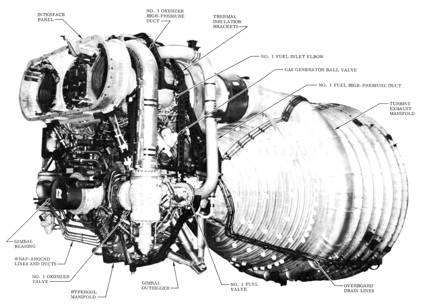
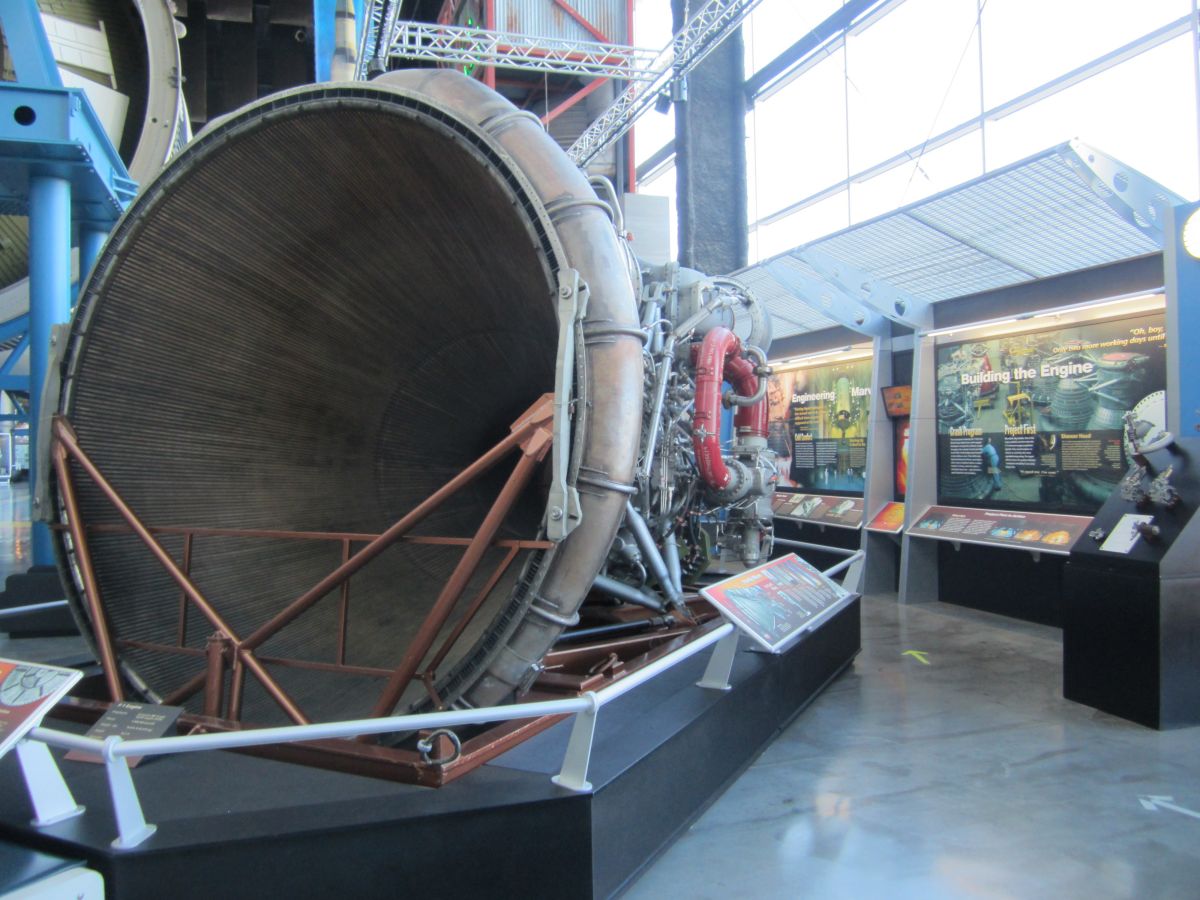
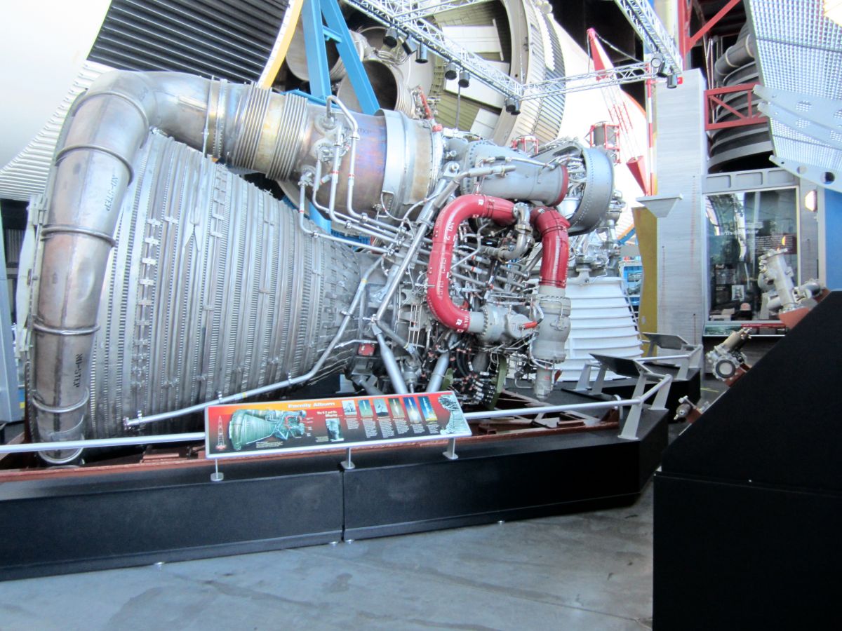
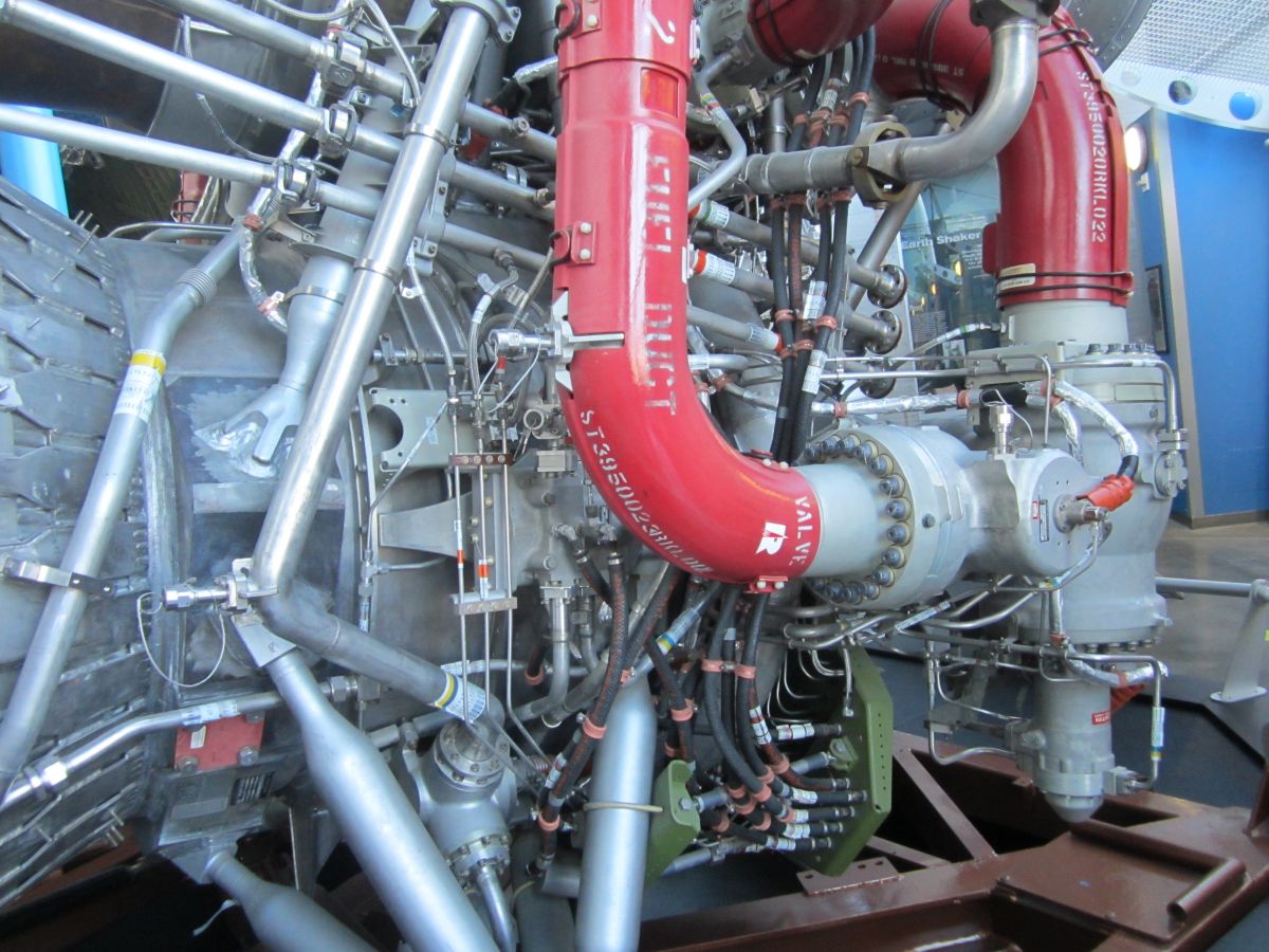
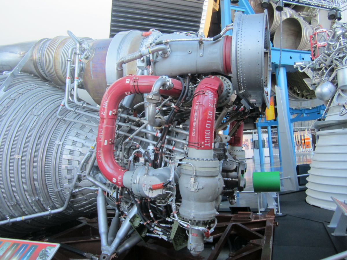
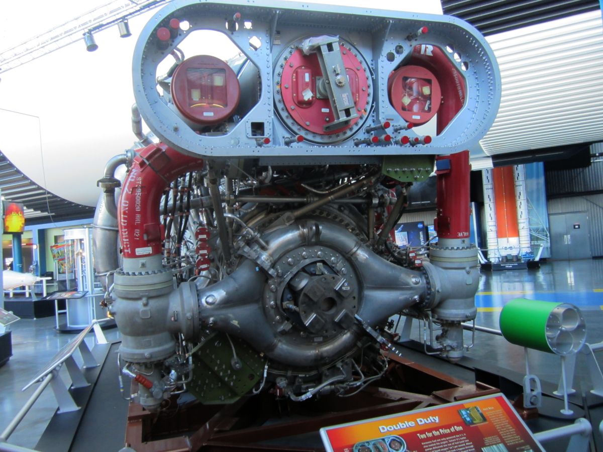
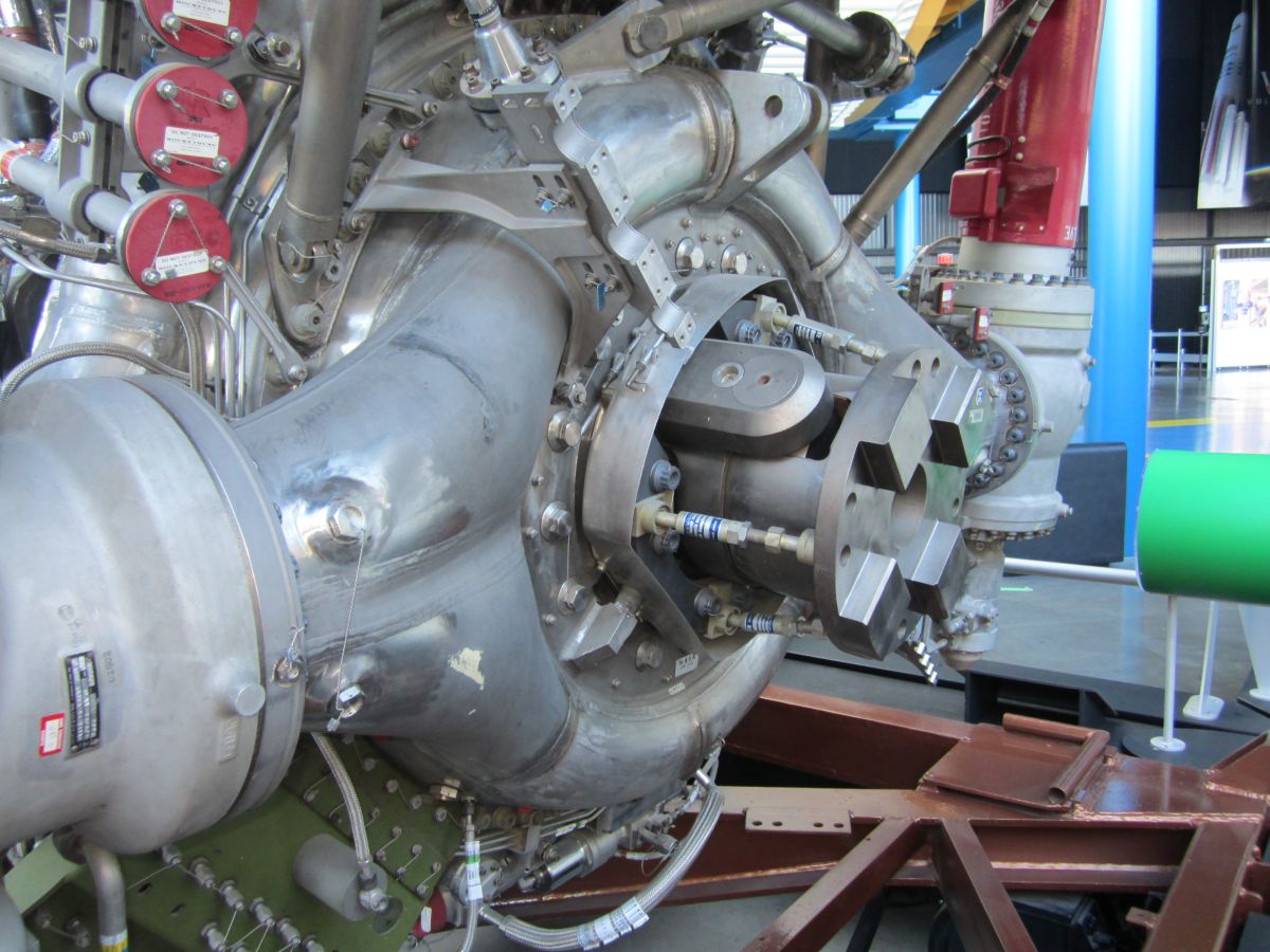
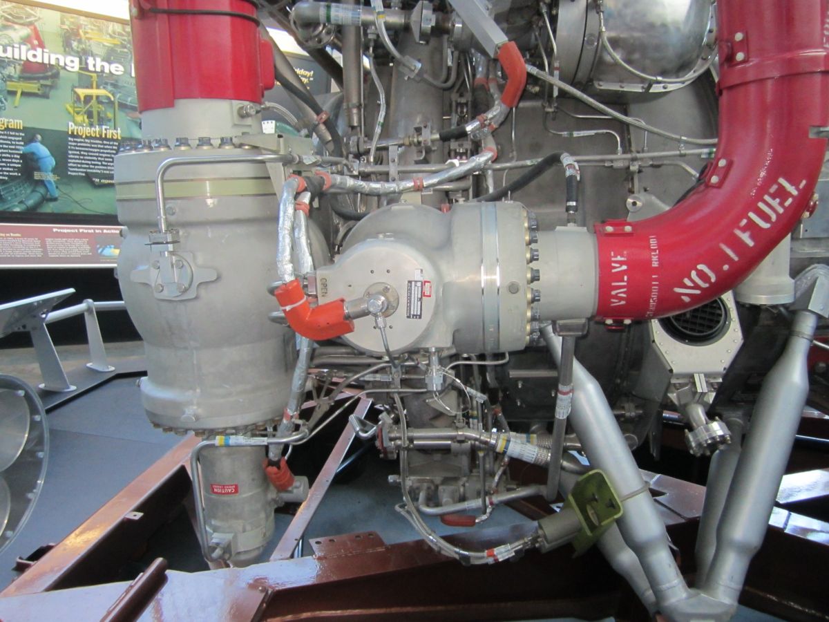
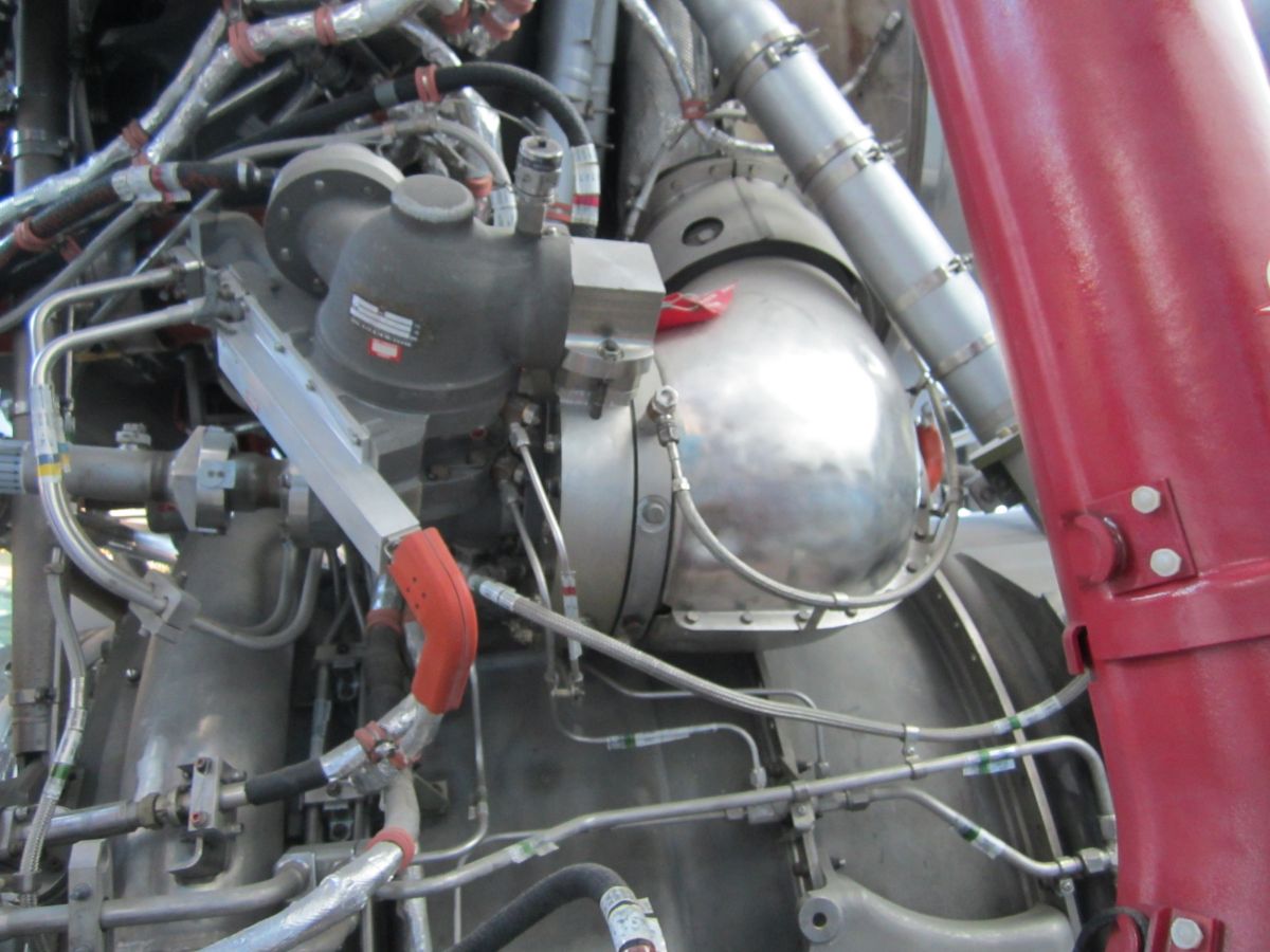
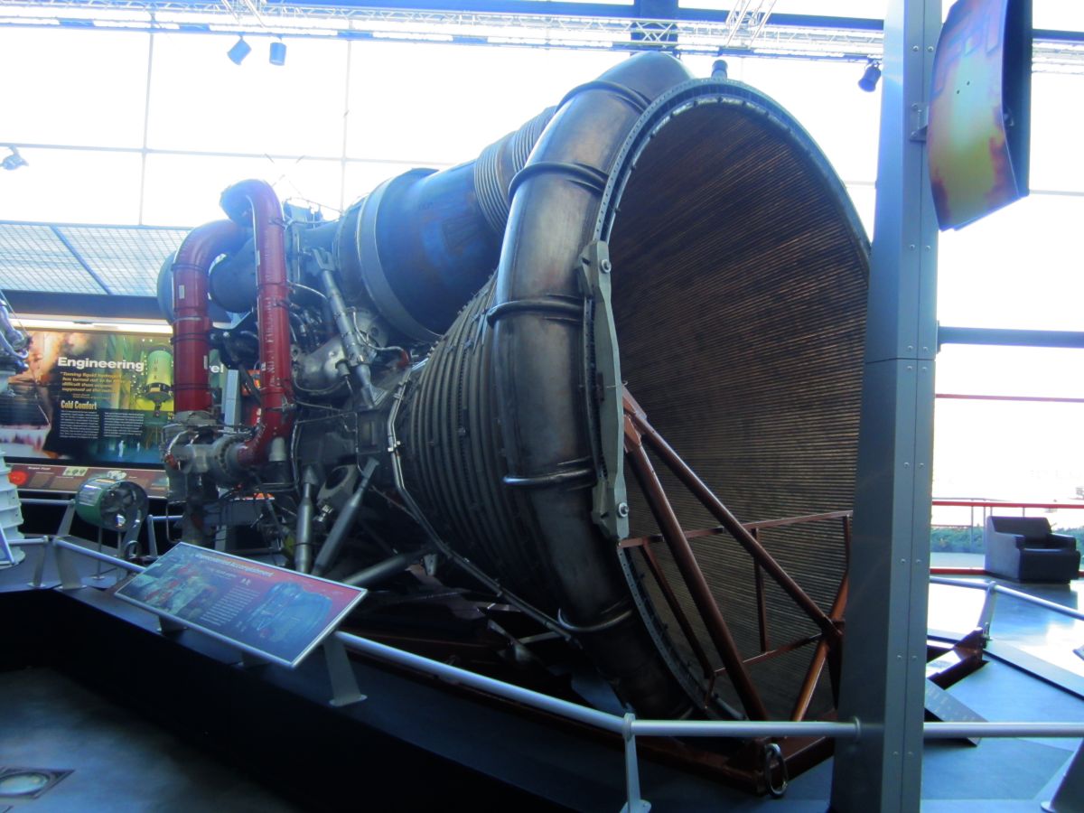
The F-1 featured a two-piece thrust chamber with tubular walls for regenerative cooling to the 10:1 expansion ratio plane, and a double-walled turbine-exhaust-gas-cooled nozzle extension to the 16:1 expansion ratio plane. A turbopump with two centrifugal pumps splined to a two-stage turbine fed four one-piece rigid propellant ducts that were used in pairs to direct fuel and oxidizer to the thrust chamber. A hypergolic fluid cartridge was used for thrust chamber ignition. The F-1 occupied a space 12 feet in diameter by 16 feet long and weighed approximately 18,500 lb dry. Thrust vector control was achieved by gimbaling the entire engine. The gimbal block was located on the thrust chamber dome, and actuator attach points were provided by two outriggers on the thrust chamber body.
The F-1 engine was a single-start, fixed-thrust, liquid bipropellant engine, calibrated to develop a sea-level-rated thrust of 1,522, 000 lb. Seven systems comprised the F-1: propellant feed, ignition, gas generator, control, instrumentation, environmental conditioning, and purge/drain.
|
|
|
| F-1 Side 1 | F-1 Forward End | F-1 Side 2 |
 |
 |
 |
 |
 |
 |
 |
 |
 |
 |
 |
 |
 |
 |
Propellant Feed System
The propellant feed system transferred oxidizer and fuel from the propellant tanks to the thrust chamber and gas generator under pressure. The system consisted a thrust chamber, a turbopump, two oxidizer valves, two fuel valves, two high-pressure oxidizer ducts, two high-pressure fuel ducts, and two fuel inlet elbows.
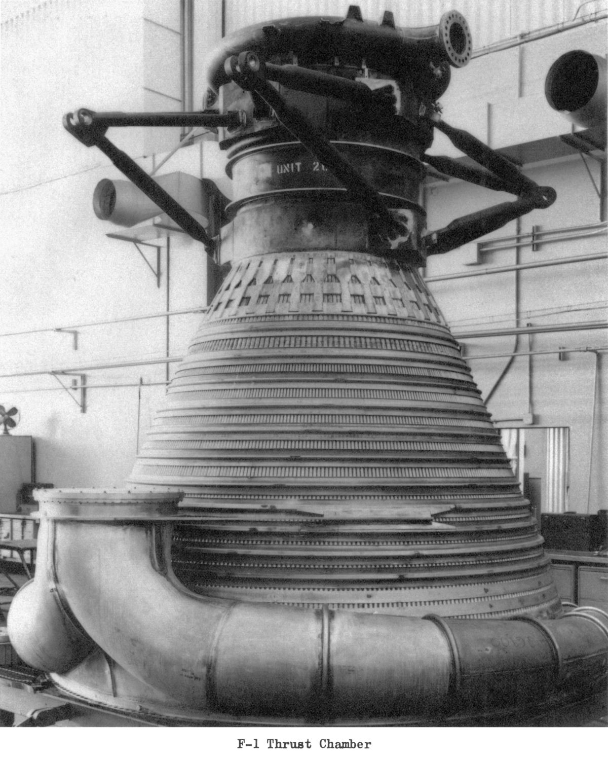
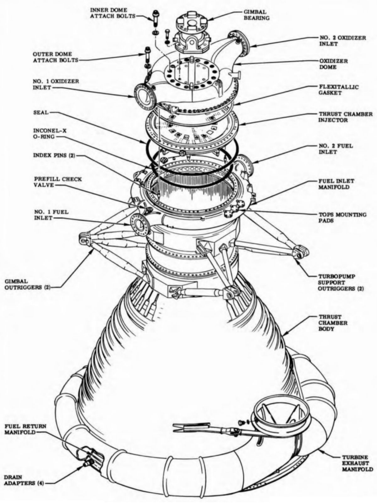
Thrust Chamber
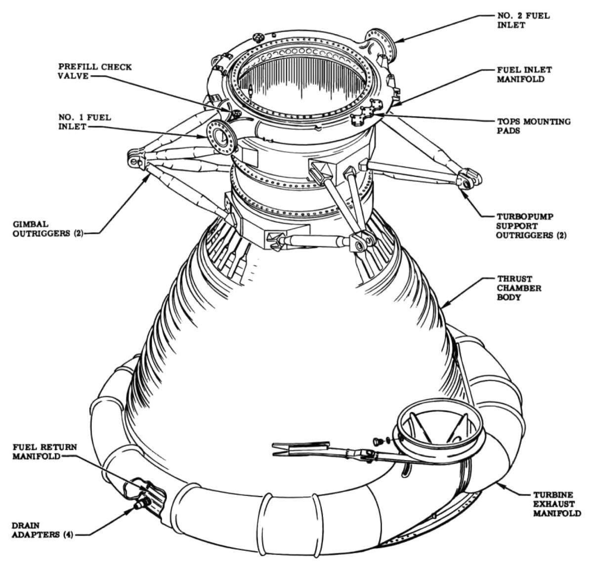
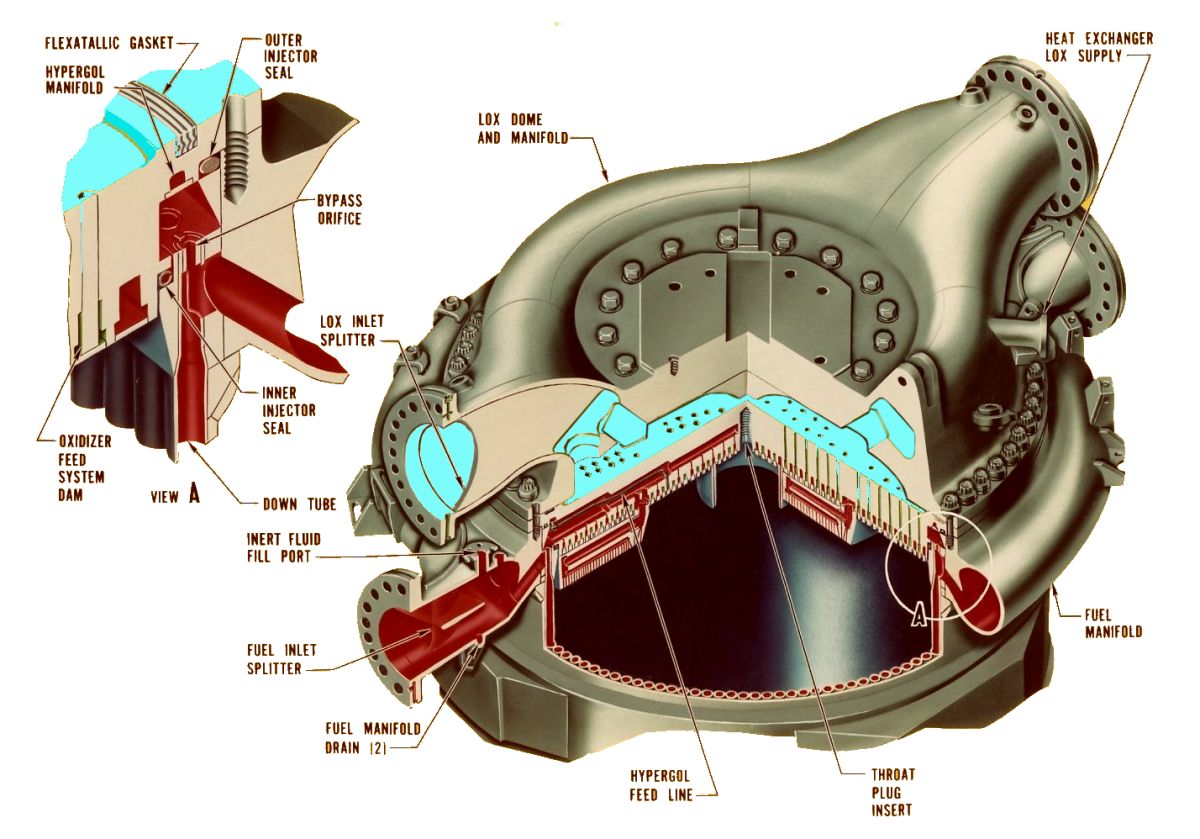
The thrust chamber assembly consisted of a two-piece thrust chamber, an injector, an oxidizer dome and manifold, and a gimbal assembly. The gimbal assembly attached to the oxidizer dome by eight bolts and he oxidizer dome was bolted to the injector by 16 inner-dome support bolts. Both the oxidizer dome and injector were bolted to the thrust chamber body by 64 outer-dome attach bolts. The dome, injector, and thrust chamber body were indexed to each other by one diamond-shaped and one round, non-interchangeable index pin, spaced 180° apart at the interface flanges below the two oxidizer dome inlets. The dome and injector mating flanges were sealed by a Teflon-filled Flexitallic gasket. The mating flanges of the injector and thrust chamber body were sealed at the outer diameter by a Viton-A O-ring and at the inner diameter by a hollow Inconel-X O-ring. The Inconel-X O-ring incorporated drilled holes in its outer diameter to permit injector manifold fuel pressure to enter the hollow section to increase its sealing capability.
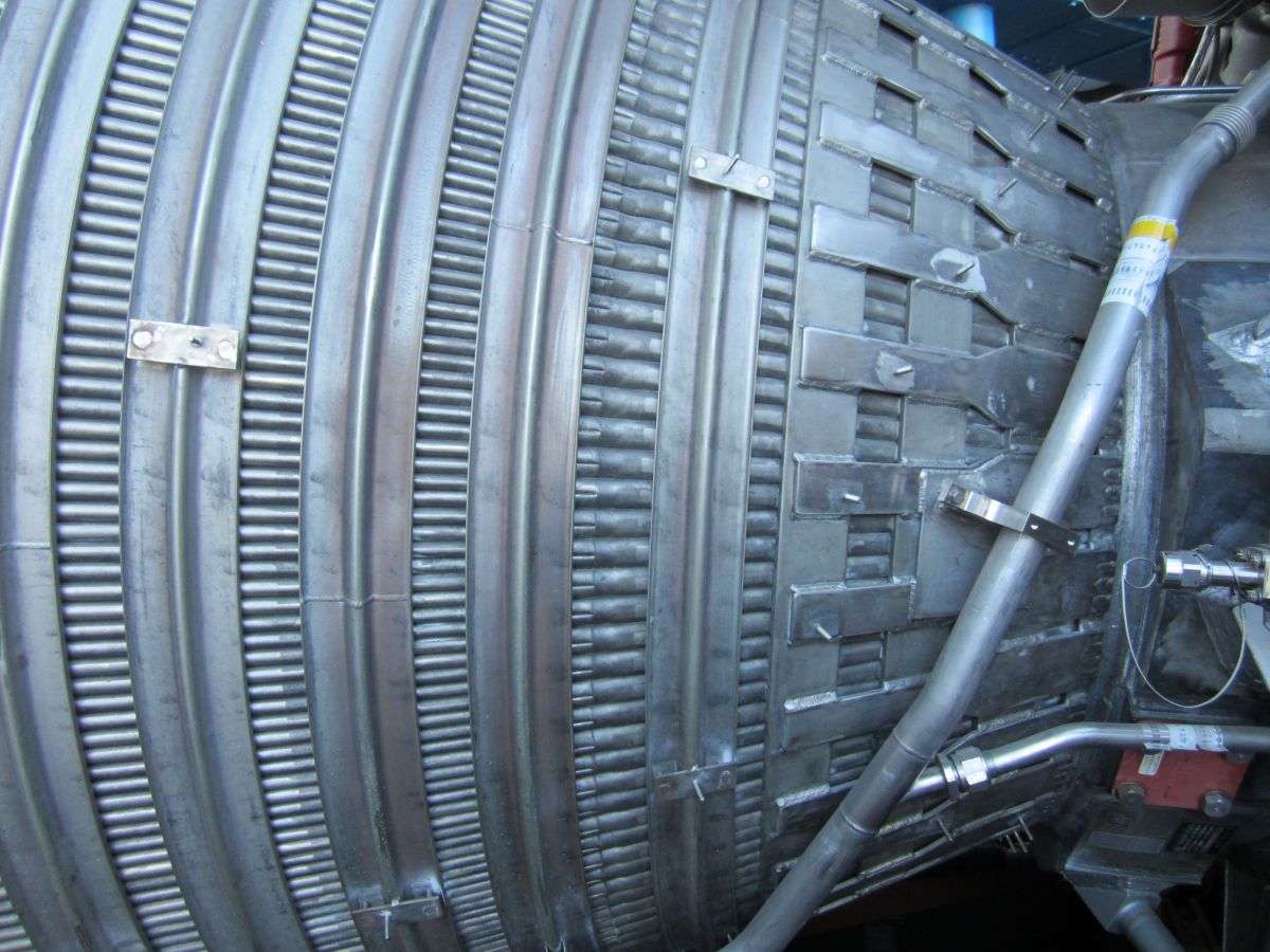
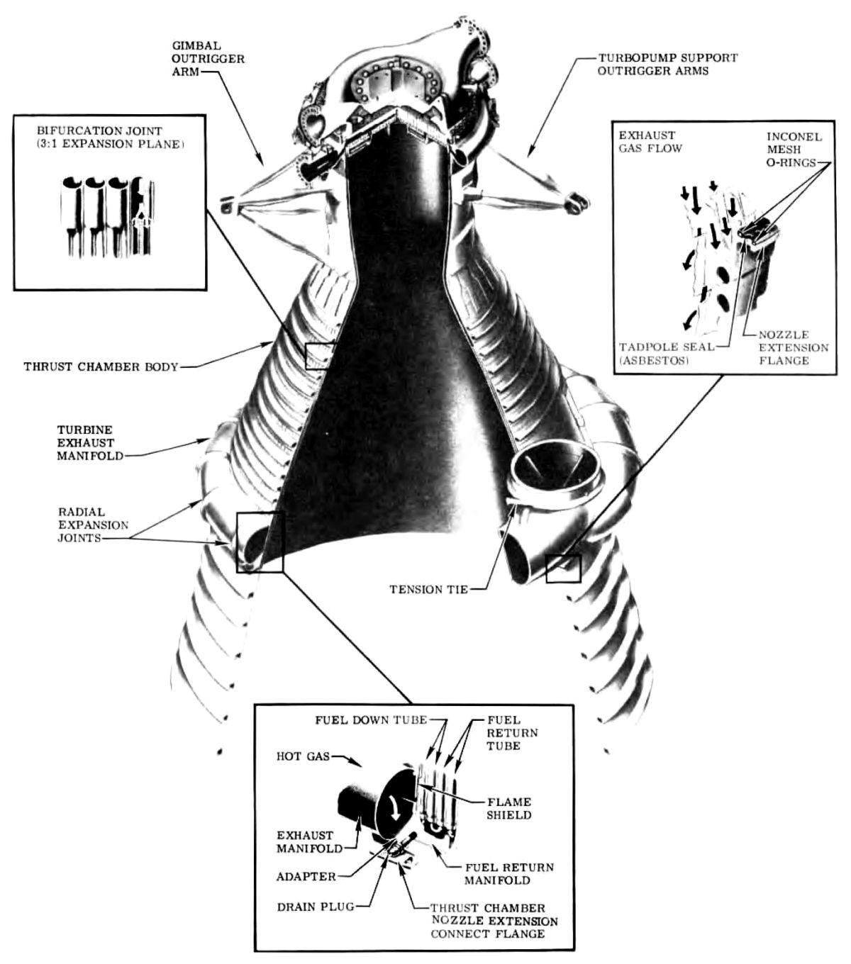
The thrust chamber body was a furnace-brazed, bell-shaped assembly incorporating two outrigger arms to support the turbopump and two outrigger arms to which the gimbal actuators attached. A fuel inlet manifold and a turbine exhaust manifold were welded to opposite ends of the chamber. A total of 178 primary tubes, each hydraulically formed from 1.093" Inconel-X tubing, made up the chamber body above the 3:1 expansion ratio plane and 356 1.000" OD Inconel-X secondary tubes formed the chamber from the 3:1 to the 10:1 expansion ratio plane. A raised weld bead with the tube number and a directional flow arrow identifed fuel-up tube No. 1 and fuel-down tubes No. 60 and 120 on the chamber internal faces of the injector end ring and fuel return manifold. External to the chamber the same tubes were similarly identified on reinforcing bands and straps below the thrust chamber throat.
Two secondary tubes were brazed to each primary tube at the 3:1 expansion ratio area plane. Every other primary tube was a fuel-down tube and was slotted on its outboard side at the fuel inlet manifold area into which fuel from the inlet manifold was directed. An orificed plug was brazed into the tube above the slot to permit 30% of the fuel to go directly to the fuel injector manifold. The remaining 70% of the fuel was used for regeneratively cooling the thrust chamber and was directed down the tube to the fuel return manifold at the end of the chamber. From the fuel return manifold, the fuel was directed by the adjacent fuel return tubes to the fuel injector manifold. The return manifold was welded to the bottom of the thrust chamber secondary tubes and incorporated four drain ports, located 90° apart, to drain residual fluids. Forty lugs were welded to the inside wall of the return manifold for attaching the turbine exhaust leak-test fixture.
The fuel inlet manifold, welded to the upper end of the chamber body, incorporated two flanges, 180° apart, for mounting the main fuel valves. A three-section flange for mounting the thrust OK pressure switches, and another for attaching the prefill check valve, were located on the inlet manifold. The fuel inlet manifold distributed fuel from the main fuel valves to the thrust chamber fuel-down tubes through angled, radial passages drilled through the inner wall of the manifold and aligned with slots in the primary fuel-down tubes.
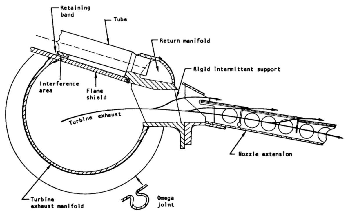
The turbine exhaust manifold collected and evenly distributed turbine exhaust gas between the nozzle extension walls. The manifold was a corrosion resistant steel (CRES) torus of decreasing (from inlet to exit) cross-sectional area incorporating 15 omega expansion joints to compensate for thermal growth. Splitter plates at the inlet and flow vanes at the exit area contributed to the uniform distribution of the exhaust gases into the nozzle extension. The exhaust manifold was welded to a flame shield that was welded to the thrust chamber outer wall.
 |
 |
 |
 |
 |
 |
| Exhaust Manifold (heriocrelics.org) |
Construction (heriocrelics.org) |
Overview | Details | Exhaust Manifold, Nozzle Extension |
Thrust Chamber |
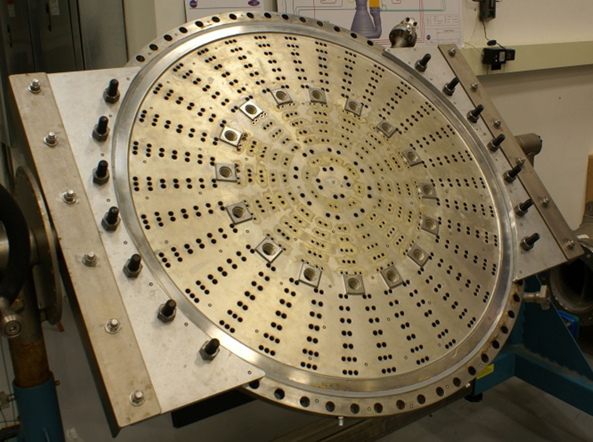
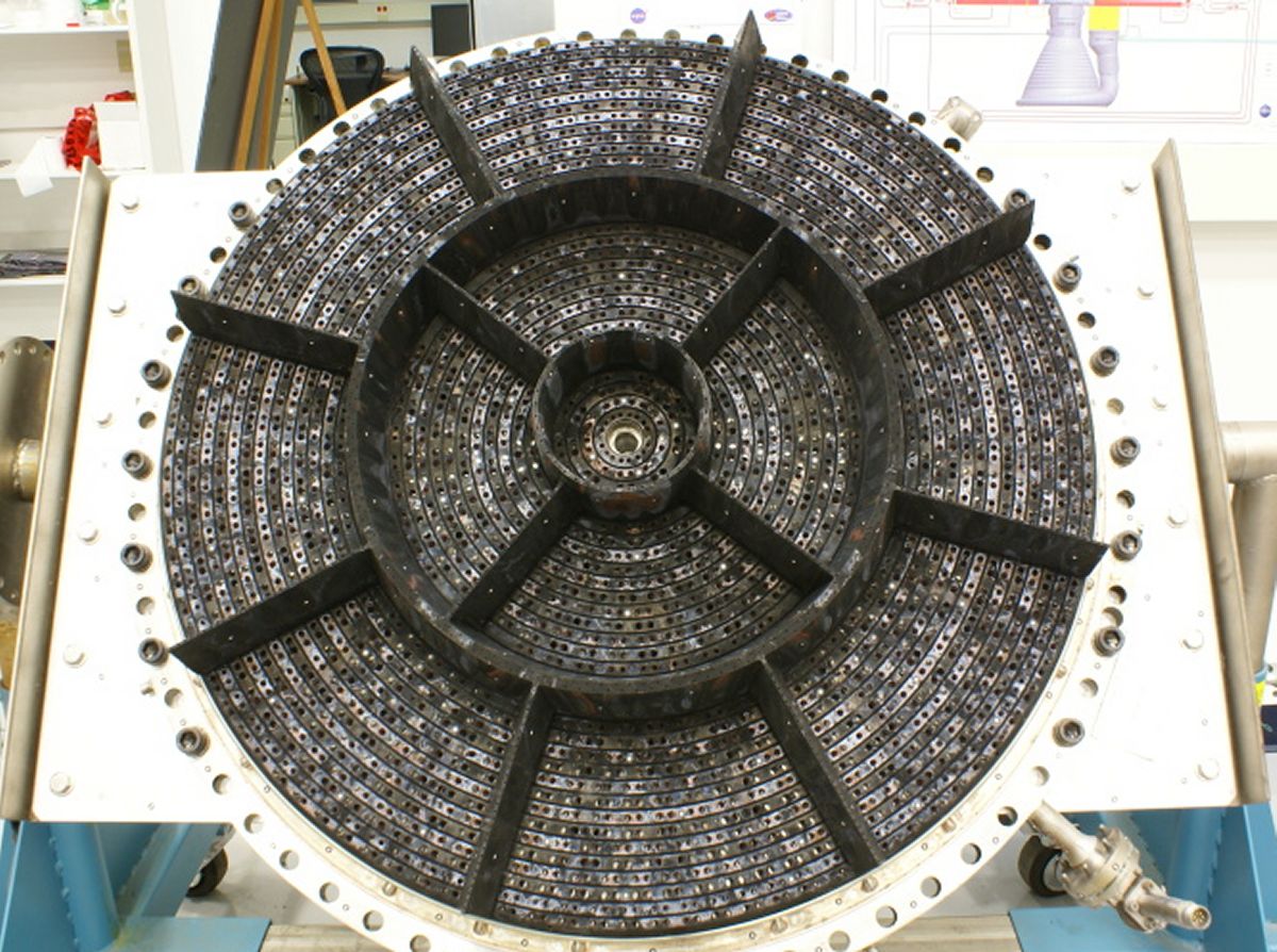
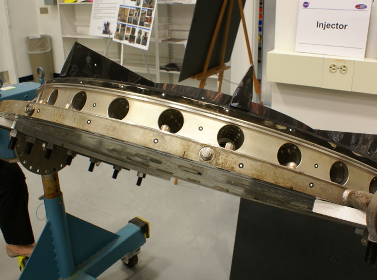
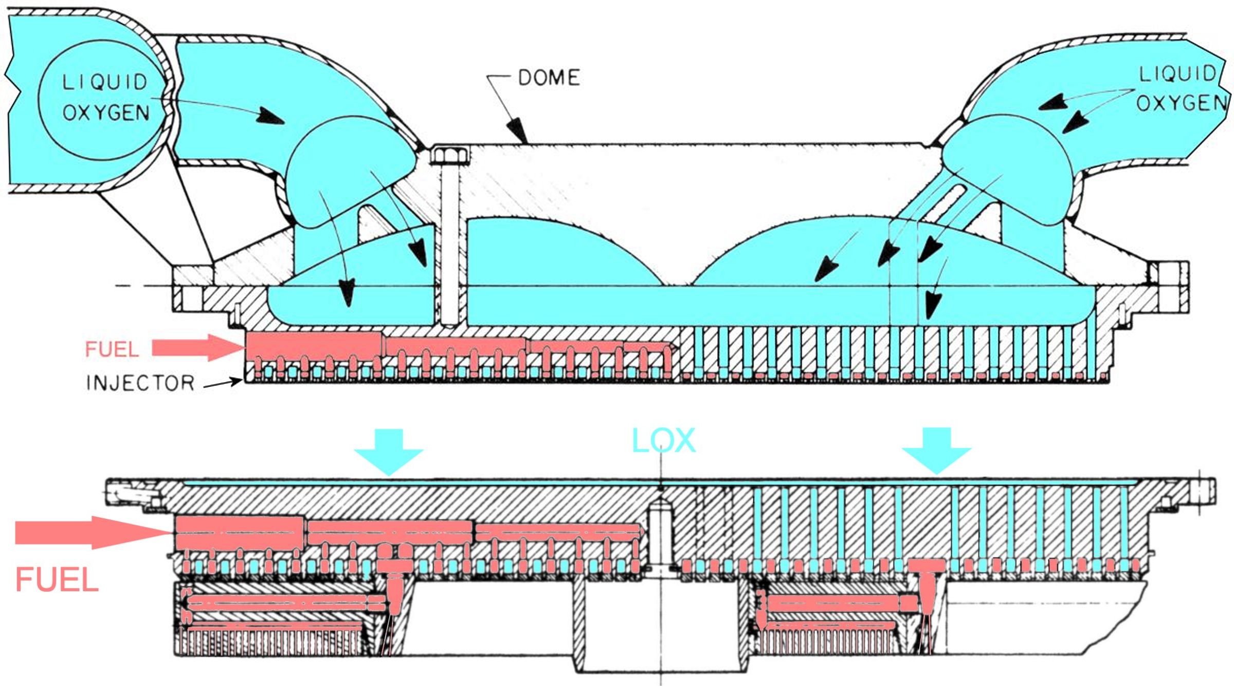
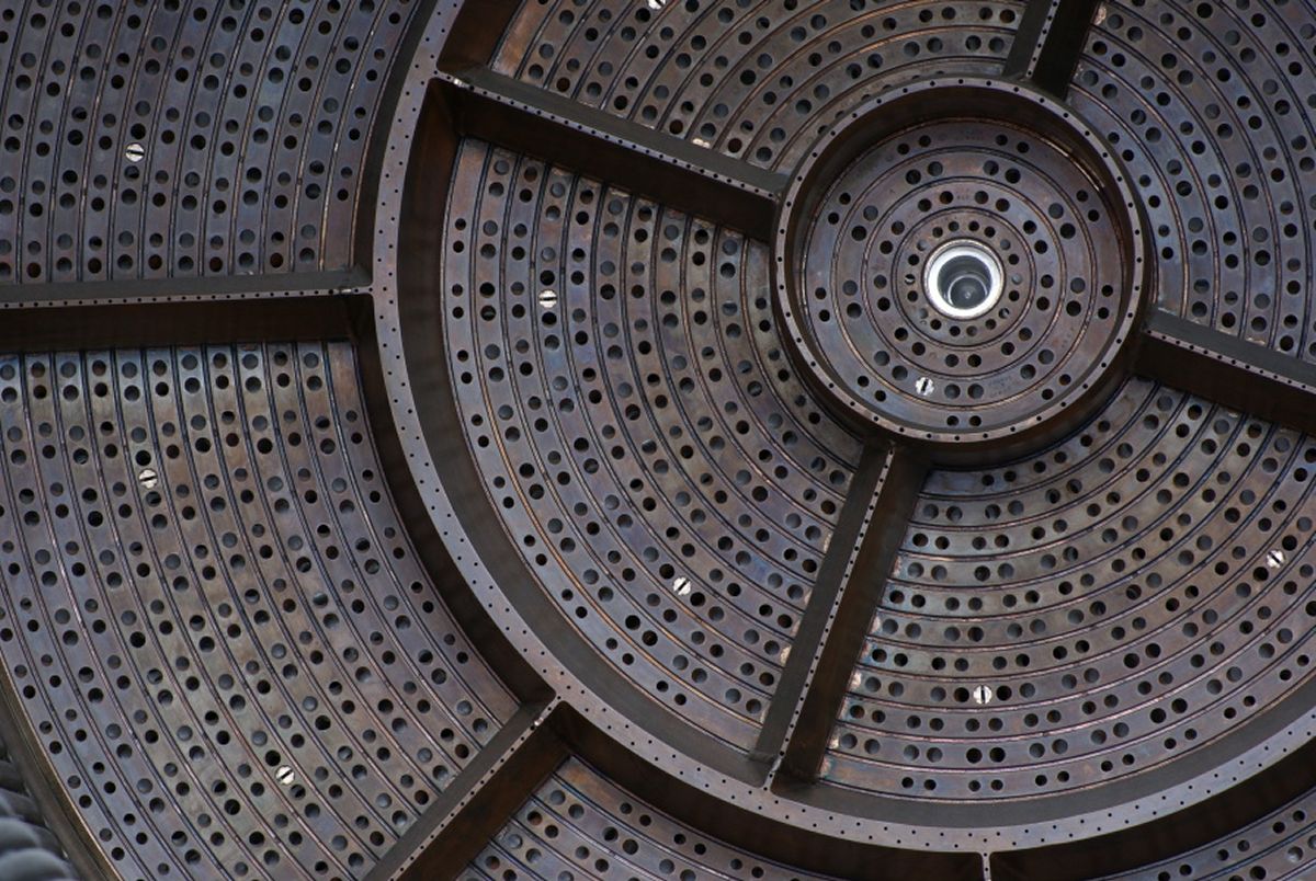
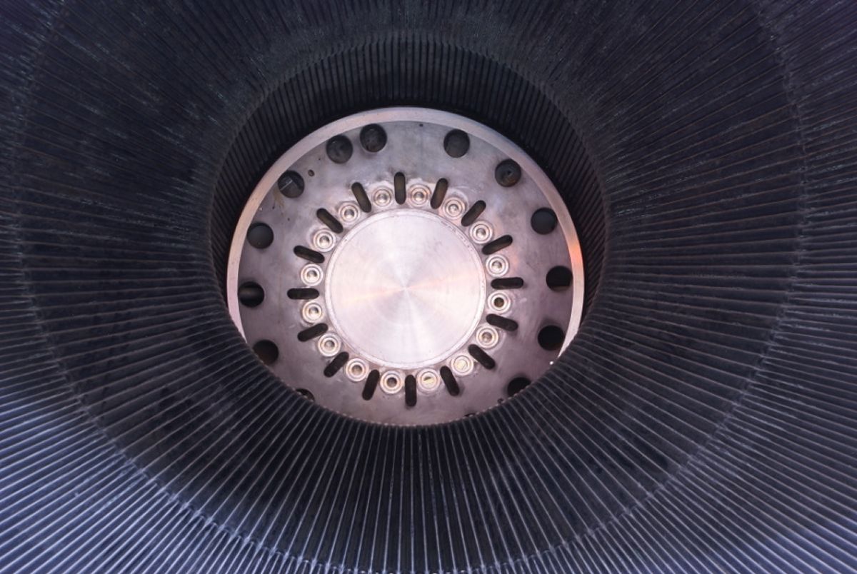
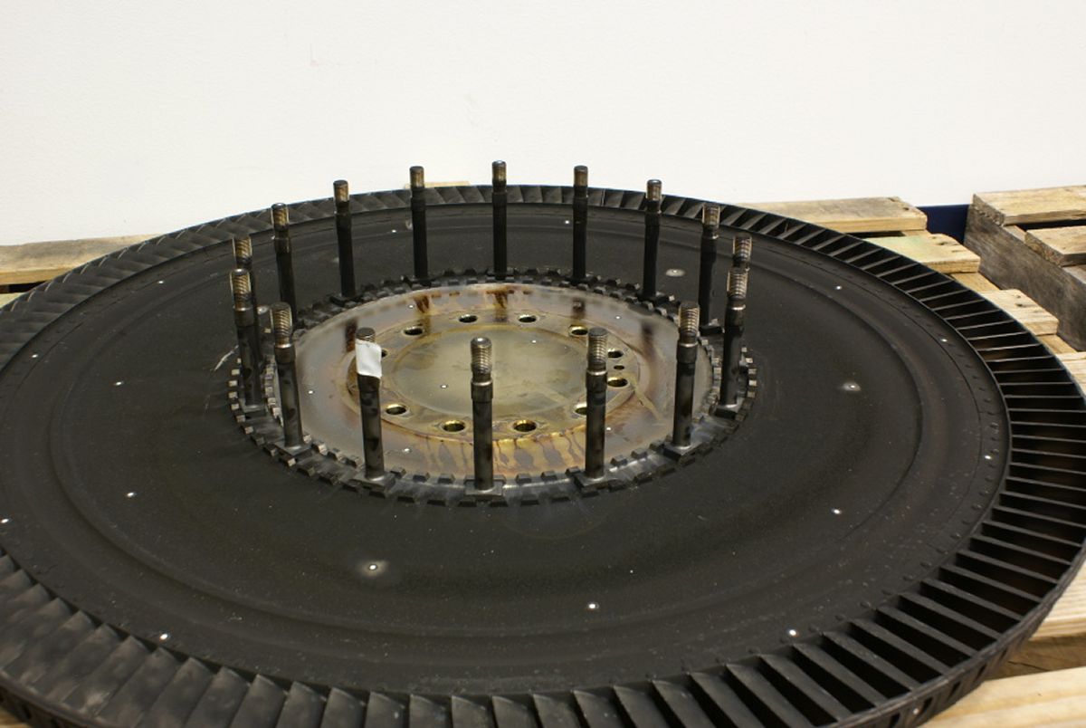
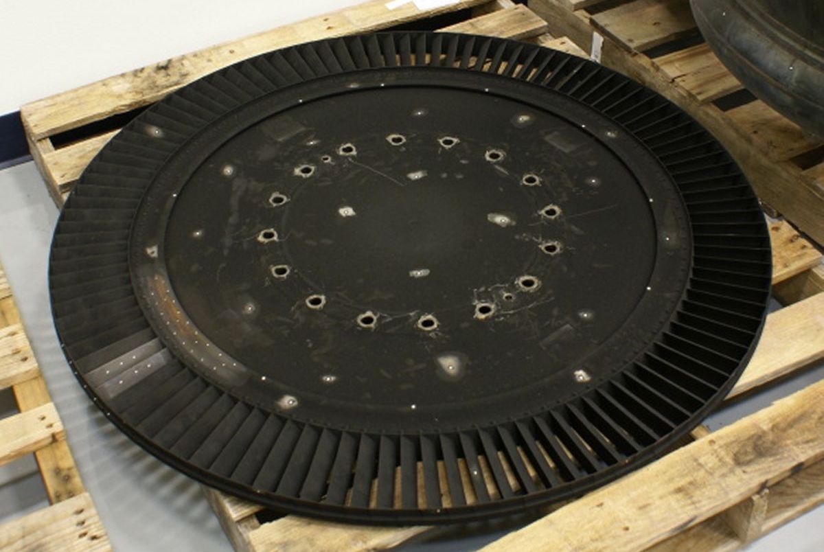
Injector
The thrust chamber injector distributed propellants into the combustion chamber at the proper mixture ratio, pressure, and spray pattern to sustain stable combustion. It was a CRES, 31-ring, plate-type injector, divided into 13 compartments by 2 circular and 12 radial baffles. The baffles dampened tangential and transverse combustion instability shock waves generated during combustion. The 31-ring grooves consisted of 16 fuel ring grooves alternating with 15 oxidizer ring grooves. The fuel ring grooves were supplied with fuel from the injector manifold by 32 radial passages, and the oxidizer ring grooves were supplied with oxidizer from the oxidizer dome by axially drilled holes. Fourteen copper rings, orifice-drilled to provide a doublet fuel-on-fuel impingement, and two circular, fuel-cooled copper baffles were brazed to the fuel ring grooves. Fifteen copper rings, orificed-drilled to provide a doublet oxidizer-on-oxidizer impingement, were brazed to the oxidizer ring grooves. The twelve radial, fuel-cooled, copper baffles were supplied with fuel by the outer circular baffle to which they were brazed. Two igniter fuel housings in each of the twelve outer compartments and one igniter fuel housing in the center compartment, connected by individual fuel feed tubes to the igniter manifold, inject igniter fuel to the compartments. The injector center was threaded for the attachment of the throat plug shaft.
 |
 |
 |
 |
 |
 |
| Cutaway (heriocrelics.org) |
Fore View (heriocrelics.org) |
Aft View (heriocrelics.org) |
Side View (heriocrelics.org) |
Sections (heriocrelics.org) |
USSRC’s (heriocrelics.org) |
 LOX Dome Top (heriocrelics.org) |
 LOX Dome Bottom (heriocrelics.org) |
Oxidizer Dome and Manifold
The oxidizer dome and manifold assembly distributed LOX to the thrust chamber injector and provided the attach point for the gimbal assembly. The assembly was a welded, CRES and nickel-base alloy unit consisting of a dome body and a torus manifold. The dome body contained the attaching flange and support posts for interfacing with the injector, and a slotted and drilled mounting flange for interfacing with the gimbal assembly. The manifold incorporated two inlets 180° apart, for mounting the No. 1 and No. 2 oxidizer valves, and a flanged boss for the heat exchanger oxidizer supply line. To prevent LOX vortexing, the manifold was isolated into two compartments by two torus dams welded at 90° from the inlets.
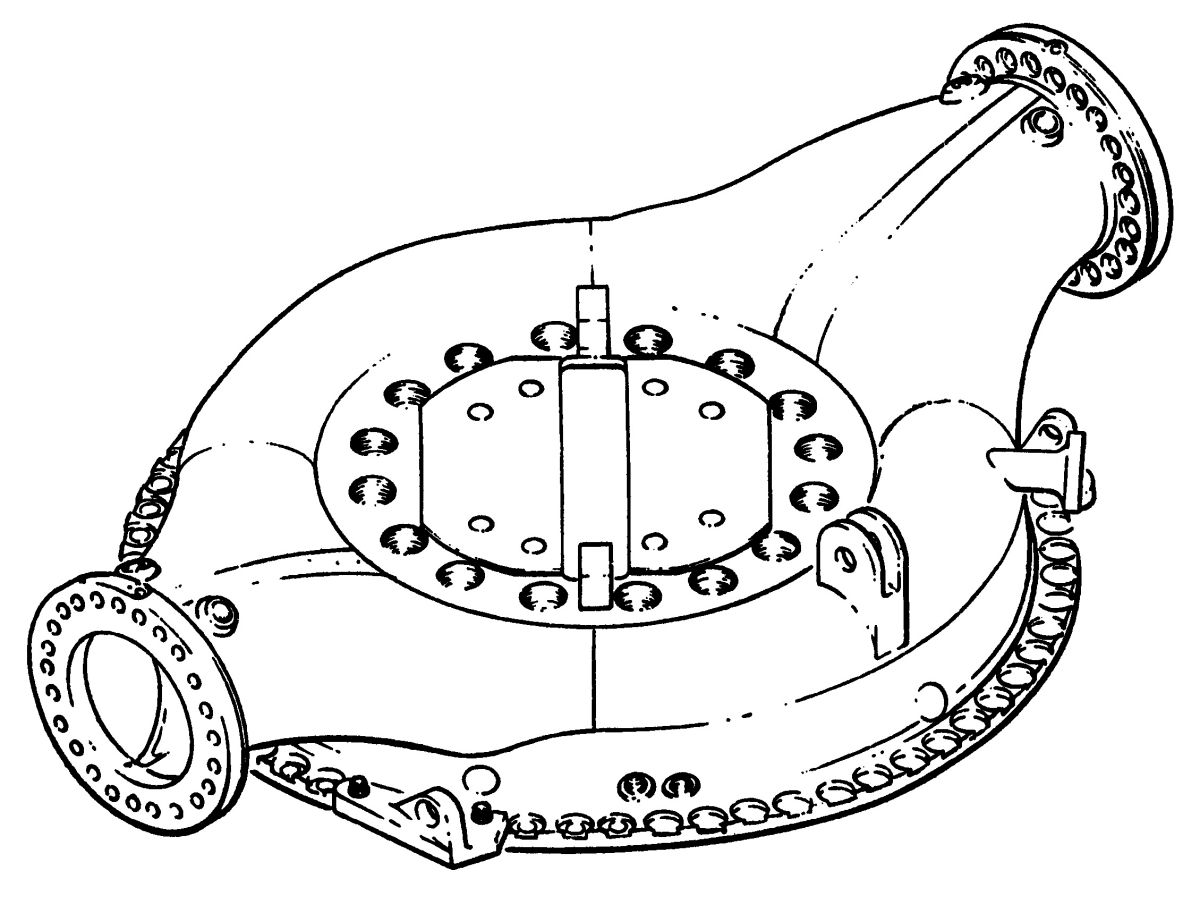
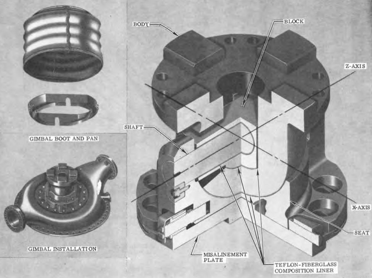
The gimbal bearing assembly permitted the engine assembly to be rotated about its x- and z-axes, providing limited control of the engine thrust vector thus allowing the guidance system to perform vehicle pitch, yaw, and roll commands. The gimbal bearing assembly was also the principal thrust interface between the engine and vehicle. The assembly was a spherical, low-friction, steel universal joint, incorporating ball- and-socket-type bearing surfaces. A composition of Teflon-impregnated fiberglass (Fabroid) was bonded to the bearing surfaces of the sockets. The main components of the gimbal assembly consist of a misalinement (yes, that is spelled correctly) plate, a seat, a body, a block, and a shaft. A silicone-impregnated fiberglass boot around the gimbal bearing protected the assembly from adverse environmental conditions. The misalinement plate was the interface between the oxidizer dome and gimbal assembly and incorporated guides and threaded-type adjustment devices to laterally position the assembly. Eight slotted holes in the plate flange, which coincided with eight threaded inserts in the dome flange, allowed lateral adjustment of the plate along the x-axis. Eight oversized holes in the seat flange, coinciding with the slotted holes in the plate, allowed lateral adjustment of the seat along the z-axis. The bottom guide recessed into a guide slot machined into the dome. The seat rested on the misalinement plate and has a guide slot into which the upper guide of the misalinement plate recesses. The seat contained the Fabroid-lined socket section within which the body ball sections moved and incorporated two arms that supported the shaft. The body was the engine interface to the vehicle. The body incorporated the ball section for the seat socket and the Fabroid-lined socket section for the ball section of the block. The block contained the ball section for the Fabroid-lined socket section of the body. The sides of the block were lined with Fabroid as were the surfaces of the hole into which the shaft fits. The shaft, through the support arms of the seat, transmitted all bearing loads between the engine and vehicle. The shaft was prevented from rotating and moving axially by two plug and screw retainers. The Fabroid liners of the gimbal assembly were lubricated at assembly and required no further lubrication.
 |
 |
| Gimbal | Nozzle Extension |
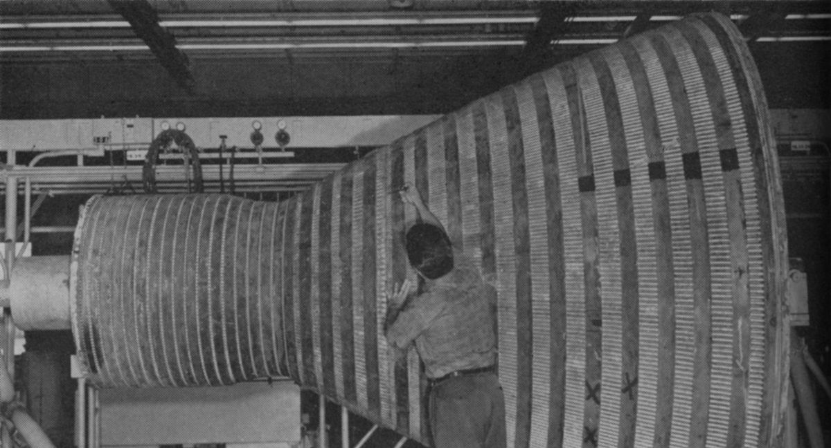
Nozzle Extension
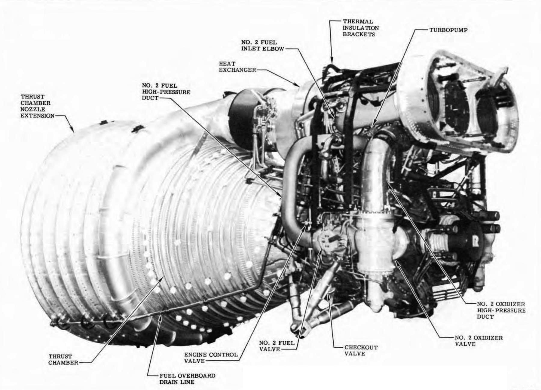
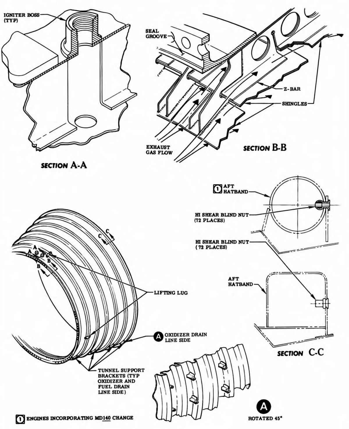
The nozzle extension increased the thrust chamber expansion ratio, providing an optimal average altitude performance. The nozzle extension was of welded construction, incorporating nickel-base-alloy inner and outer walls, separated by z-sections with CRES reinforcing channel bands welded to the outer wall circumference. Film cooling of the inner walls was achieved by injecting turbine exhaust gas, supplied to the cavity between the walls by the turbine exhaust manifold, into the thrust chamber exhaust stream through injector slots formed by 23 rows of overlapping shingles that comprised the inner wall. The thrust chamber nozzle extension was bolted to the thrust chamber exit-end ring after the engine was installed in the vehicle.
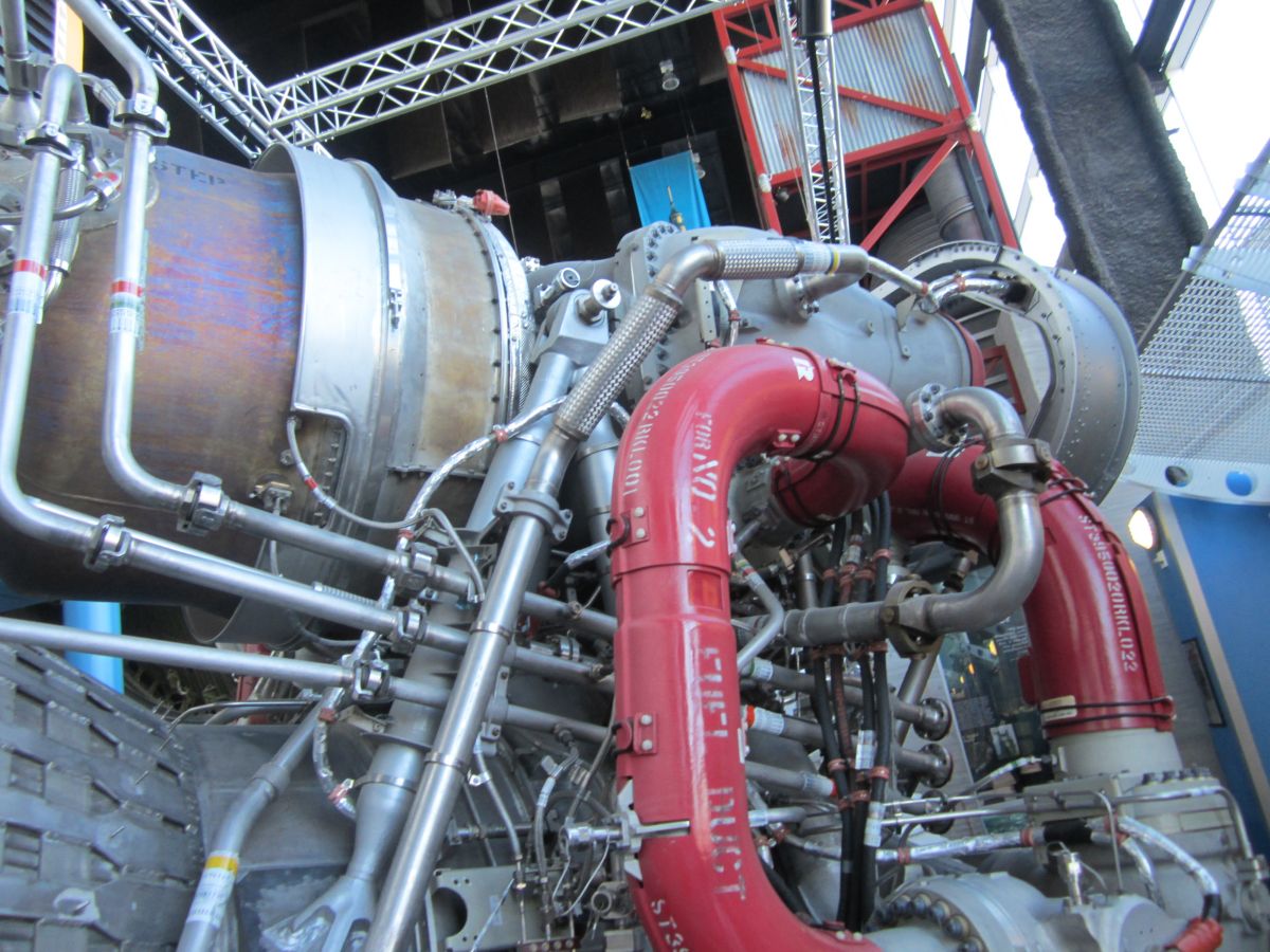
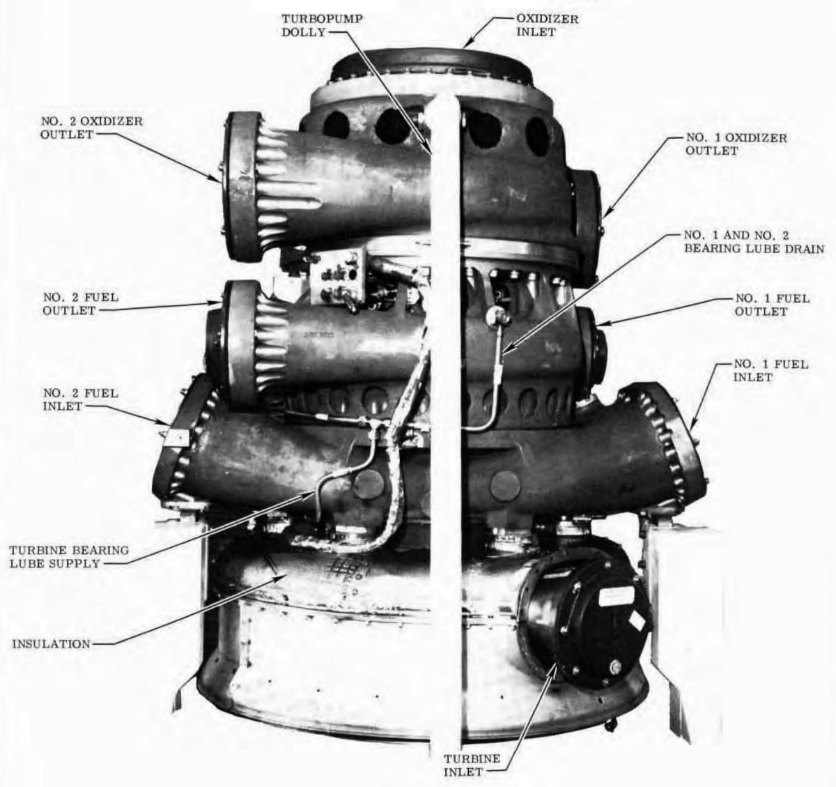
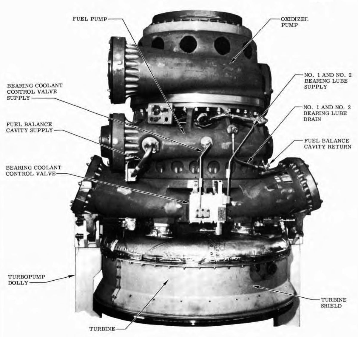
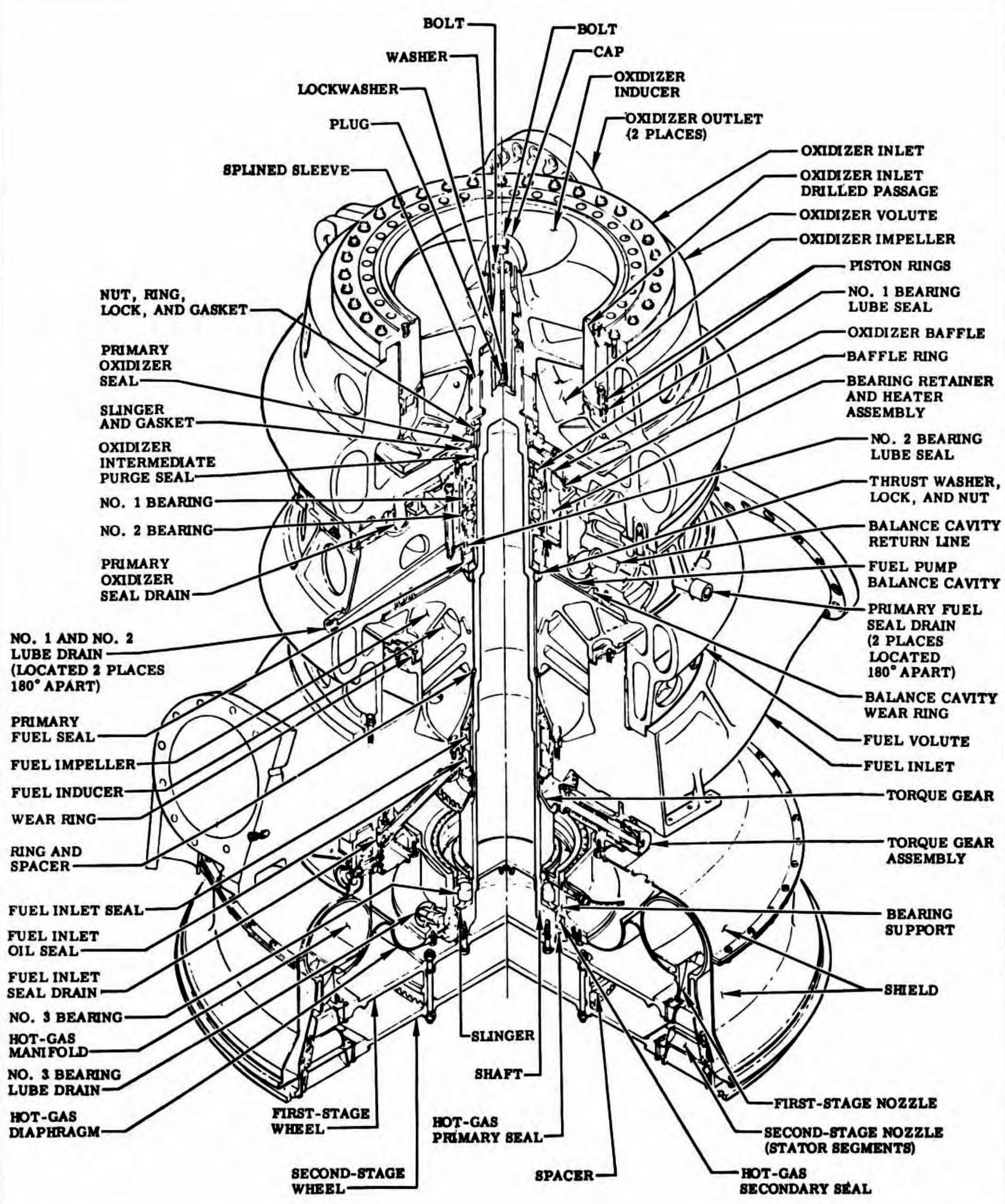
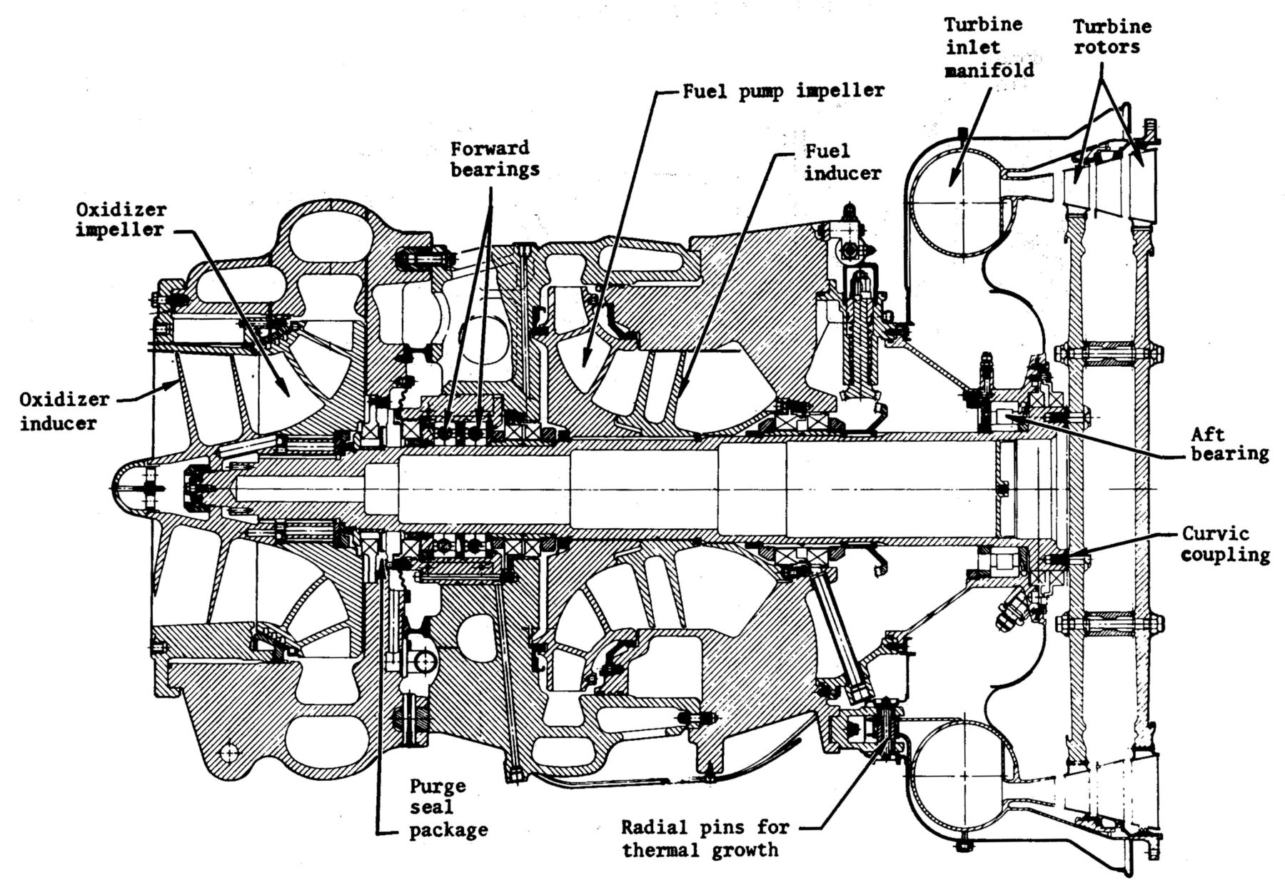
Turbopump
 Turbopump Inboard |
 Turbopump Outboard |
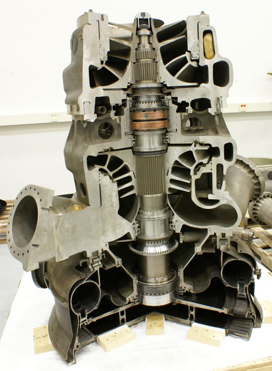
The MK-10 turbopump assembly delivered propellants to the engine system at rated pressures and flowrates. The assembly was mounted parallel to the thrust chamber longitudinal centerline and was primarily supported by two three-legged outrigger assemblies welded to the chamber body and by the four high-pressure propellant ducts installed between the turbopump and the thrust chamber. The turbopump assembly was composed of two centrifugal pumps mounted back-to-back on a common shaft, directly driven by a two-stage, velocity compounded, impulse gas turbine. The main shaft and the rotating components that attached directly to the shaft were dynamically balanced as an assembly prior to turbopump final assembly. Plugs in the fuel impeller and weights in the turbine wheels were installed as required during the procedures to achieve the required balance. Dual discharge ports on each of the pumps balanced radial loads on the assembly. The shaft was supported by twin electrically heated, fuel-cooled ball bearing assemblies at the oxidizer pump area, and one fuel-cooled roller bearing assembly at the turbine area. Six carbon-nose and three carbon-segmented seals, augmented by plastic (Kel-F, Teflon) and synthetic rubber (Buna-N, Viton-A) seals, performed sealing functions to isolate the propellants, cooling fluid, and hot gases to their respective areas.
The turbopump contained a force balancing system to control the axial thrust loads imposed upon the shaft and ball bearing assemblies by the forces primarily generated by the differential pressure across the oxidizer impeller. The balancing system utilized the area between the back of the fuel impeller and fuel volute as a balance cavity, to which fuel pressure from the discharge side of the fuel pump was directed and regulated, partially counterbalancing the axial thrust developed by the oxidizer impeller. Manual rotation of the turbopump shaft for the purpose of facilitating turbopump preservation and detecting excessive breakaway and running torque, was provided by a ring and pinion gear combination. The ring gear was splined to the turbopump shaft, and the pinion gear was mounted to the torque gear housing in a spring-loaded, disengaged position. When manual rotation of the pump shaft was required, the pinion gear was pushed in to engage with the ring gear and a rotating force applied. The sleeve of the ring gear contained two holes, spaced 180° apart, which were used in conjunction with a magnetic transducer for monitoring shaft speed during engine operation.
Turbopump bearings were cooled by pressurized fuel supplied through a bearing coolant control valve to spray nozzles at the bearings. The fuel was routed in parallel from the coolant control valve to the No. 1 and No. 2 bearings and to the No. 3 bearing and was then drained overboard through the fuel overboard drain system. On engines incorporating MD145 change, the parallel routing from the bearing coolant control valve was been replaced by a series system. This change directed the drainage from the No. 1 and No. 2 bearings to splash-lubricate the No. 3 bearing and then overboard through the overboard drain system. Two cal-rod heaters, cast into the retainer block of the No. 1 and No. 2 bearings, prevented condensation and ice from forming on the bearings during engine standby.
The principal turbopump sections consisted of an oxidizer pump section, a fuel pump section, and a turbine section. The three sections were structurally connected to each other by pins, which permit relative radial movement to compensate for the effects of thermal differences between the oxidizer, fuel, and turbine sections. A bearing coolant control valve mounted on the fuel pump section supplies coolant fuel to the bearings contained within the oxidizer pump and turbine sections.
The oxidizer pump included an inducer, an impeller, a volute, two bearings, and the necessary seals to contain the oxidizer and coolant fuel within their respective areas of the oxidizer pump section. The inducer was splined to the shaft and increased the oxidizer inlet pressure to prevent cavitation and to direct the oxidizer into the inlet of the impeller. The impeller was installed on the shaft through an internally/externally splined coupler and imparted velocity to the fluid. The volute housed and supported the component parts of the oxidizer pump and converts the kinetic energy of fluid velocity to potential energy of fluid pressure. The oxidizer volute incorporated a ring that was pinned within a recess of the volute by 36 radially inserted pins. The fuel volute attached to this ring by 36 bolts that were axially installed into threaded holes of the ring. Two discharge ports supplied oxidizer to respective inlets of the oxidizer dome and manifold assembly. The bearings at the oxidizer pump section, identified as No. 1 and No. 2 bearings, were a matched set of ball bearings that supported the shaft at its forward end and absorb shaft axial loads.
Four major seals were contained in the oxidizer pump section. No. 1 seal (primary oxidizer seal) was a carbon-nose-to-mate-ring seal that seals the oxidizer propellant area from the bearing coolant fuel area. Leakage past this seal was directed overboard through the oxidizer overboard drain line. No. 2 seal (intermediate oxidizer seal) was a carbon-segmented seal with the spring-loaded carbon segments riding against the pump shaft and was a backup seal to isolate the oxidizer from the fuel coolant. A nitrogen gas purge was applied between the two segment layers and flows axially in both directions between the faces of the carbon segments and the shaft. Because carbon seals were primarily dynamic seals, the purge acts as a positive pressure barrier to isolate the oxidizer and bearing coolant from each other under static conditions. The purge flow to the oxidizer side of the seal was directed overboard through the same line that drains the primary oxidizer seal cavity. No. 3 seal (No. 1 bearing lube seal) was a carbon-nose-to-mate-ring seal, which was the forward seal to confine the bearing coolant fluid within the bearing retainer and heater assembly. Leakage past No. 3 seal, along with the purge gas flowing from the coolant side of the intermediate oxidizer seal, was directed overboard by the nitrogen purge overboard drain line. No. 4 seal (No. 2 bearing lube seal) was a carbon-nose-to-mate-ring seal, which was the rear seal to confine the bearing coolant fluid within the bearing retainer and heater assembly. Leakage past No. 4 seal was directed to the fuel drain manifold by the primary fuel seal drain lines. Additional seals of the oxidizer pump section include two Kel-F coated, CRES, split piston rings, a Teflon-coated Naflex seal, and Kel-F wear ring seal. The split piston rings recess into grooves of the oxidizer inlet and seal the interface of the oxidizer inlet skirt and volute wall. Any leakage past both seals was directed back to the inlet side of the pump through radial passages drilled in the oxidizer inlet assembly. The Naflex seal was installed between the attach flanges of the oxidizer inlet and the oxidizer volute. The Kel-F wear ring was a labyrinth seal attached to the oxidizer inlet. The wear ring effectively sealed the high-pressure side of the pump from the low-pressure side by placing a series of orifices and expansion areas between the two sides. Synthetic rubber O-rings were also used in the carbon seal assemblies and in the bearing retainer and heater assembly.
 |
 |
 |
 |
 |
 |
 |
| Cutaway (heriocrelics.org) |
Drawing (heriocrelics.org) |
Cross Section (heriocrelics.org) |
Fuel Pump (heriocrelics.org) |
Turbine (heriocrelics.org) |
Turbine Stage 1 (heriocrelics.org) |
Turbine Stage 2 (heriocrelics.org) |
The fuel pump included an inlet assembly, an inducer, an impeller, a volute, and the necessary seals to contain the fuel within the fuel section of the pump. The fuel inlet assembly was a dual inlet manifold that directs fuel to the inducer. The inlet assembly was bolted to the fuel volute on the top side and to the torque gear housing on the bottom. Six clevis fittings on the turbine section were bolted to the fuel inlet assembly to provide the primary structural interface between the fuel pump section and the turbine section. The inducer was splined to the shaft and increases the fuel inlet pressure to prevent cavitation and to direct the fuel into the eye of the impeller. The impeller was splined to the shaft and imparted velocity to the fuel. The volute converted the fuel's kinetic energy to the potential energy of fluid pressure. Thirty six bolts connected the fuel volute to a pinned ring of the oxidizer volute to provide the primary structural interface between the fuel pump section and the oxidizer pump section. The fuel volute incorporated two discharge ports that supplied fuel to the thrust chamber fuel inlet manifold.
Three major seals were contained in the fuel pump section. No. 5 seal (primary fuel seal) was a carbon-nose-to-mate-ring seal, which sealed the shaft area of the balance cavity. Any leakage past this seal, along with any leakage past the No. 4 seal, was directed to the fuel drain manifold by the primary fuel seal drain lines. No. 6 seal (fuel inlet seal) was a carbon-nose-to-mate-ring seal that sealed against leakage from the fuel inlet. Any leakage past this seal was directed to the fuel drain manifold by the fuel inlet seal drain lines. No. 7 seal (fuel lube seal) was a carbon-nose-to-mate-ring seal that prevented leakage of coolant fuel from the bearing support area. Any leakage past No. 7 seal would be directed to the fuel drain manifold, along with any leakage past the No. 6 seal, by the fuel inlet seal drain lines. Additional seals of the fuel pump section included three synthetic rubber O-rings and two lead-plated brass wear rings. Two of the synthetic O-rings sealed the interface of the fuel inlet skirt and wall of the volute. The other O-ring sealed the torque gear housing and fuel inlet interface. One of the wear rings, which was a labyrinth-type seal bolted to the fuel inlet assembly, effectively sealed the high-pressure pump side from the low-pressure side by placing a series of orifices and expansion areas between the two sides. The other wear ring, which was bolted to the volute and extended into a groove in the backside of the impeller, was a labyrinth-type seal and, in conjunction with the primary fuel seal, established the outer and inner diameters of the fuel balance cavity.
The turbine section consisted of the turbine inlet manifold, two turbine wheels, one bearing, and the necessary seals to contain the hot gas within the turbine section. The turbine inlet manifold housed the turbine components and incorporated six spools to provide a structural interface between the turbine section and the fuel pump section. Each spool had an individually matched clevis fitting, which bolted to the fuel pump inlet, and a clevis pin, which was identified with the manifold serial number and a dash number corresponding to the spool position to which they were matched.
The turbine manifold featured an inlet flange to which the gas generator combustor was attached and an outlet flange for heat exchanger attachment. A nozzle assembly welded to the inlet manifold directed gas generator gases onto the first-stage turbine wheel blades, and 10 nozzle segments bolted to the inlet manifold directed gases from the turbine first-stage onto the second-stage blades. Each turbine wheel consisted of a disc incorporating a series of fir tree slots in its outer periphery into which blades were inserted and riveted in place. The first-stage wheel was attached to the main shaft via a bolted curvic coupling that absorbed the high shear loads experienced during engine start. The second-stage wheel was bolted to the first-stage wheel through a dual curvic coupler spacer. The bearing in the turbine section was identified as the No. 3 bearing and was a roller bearing that supported the main shaft at the turbine end and absorbed radial loads imposed on the shaft. The bearing was supported by the turbine bearing support assembly, which was bolted to the torque gear housing and the turbine inlet manifold assembly.
Two major seals were contained in the turbine section. No. 8 seal (hot-gas secondary seal) and No. 9 seal (hot-gas primary seal) were both carbon segmented seals with the spring-loaded segments riding against the pump shaft. The seals isolated turbine section hot gases from the No. 3 bearing. Other seals in the turbine section consisted of two pressure-actuated seals and a honeycomb seal. One of the pressure-actuated seals, which was installed at the interface of the hot-gas secondary seal housing and the bearing support assembly, sealed against leakage of coolant fluid into the turbine inlet manifold. The other pressure-actuated seal, which was installed at the interface of the bearing support assembly and the turbine inlet manifold assembly, sealed against leakage of hot gas from the turbine inlet manifold. The honeycomb seal was an Inconel honeycomb circular strip positioned on the inner wall of the turbine inlet manifold at the area of the first-stage turbine wheel. The seal in conjunction with two machine serrations on the turbine wheel blades was a labyrinth-type seal that effectively prevented the bypassing of gas around the periphery of the wheel.
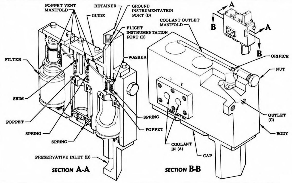 Bearing Coolant Control Valve |
The bearing coolant control valve controlled the coolant fuel flow to the turbopump bearings and provided a means of supplying preservative compound to the bearings. It was a normally closed, spring-loaded, pressure-actuated, redundant poppet valve that assured positive delivery of coolant fluid. The valve assembly consisted of two coolant and one preservative-oil poppet valves, three 40-micron filters, a restrictor to meter the coolant fuel, and a housing that incorporated a quick-disconnect for attaching the preservative oil supply line. The redundant fuel coolant poppets offseat when fuel pump discharge pressure reached a nominal 225 psig and directed coolant through the restrictor to the turbopump bearings. The restrictor was sized during engine acceptance testing to provide a bearing pressure of 200 - 540 psig. The preservative-oil poppet would offseat during preservation procedures at 9-20 psig and direct preservative oil to the turbopump bearings. On engines incorporating MD145 change, the port for the turbine bearing jet ring was capped and the orifice was changed to accommodate the series lube system.
The turbopump fuel inlet elbows were single-inlet, dual-outlet elbows incorporating internal flow vanes. Fuel flowed radially into the fuel pump inlet assembly from the two inlet elbows mounted 180° apart. Lifting studs were provided on the elbows for ease of handling. Seal monitoring ports were provided on the downstream outlet flanges. One attach point for support of the engine interface panel was located on each elbow, and attach points were located on the duct side of the elbow for fastening a flexible (rubber) thermal insulation boot around the blow to the engine interface panel. The No. 2 elbow had a flanged attach point for the checkout valve engine return hose.
 Main Oxidizer Valve |
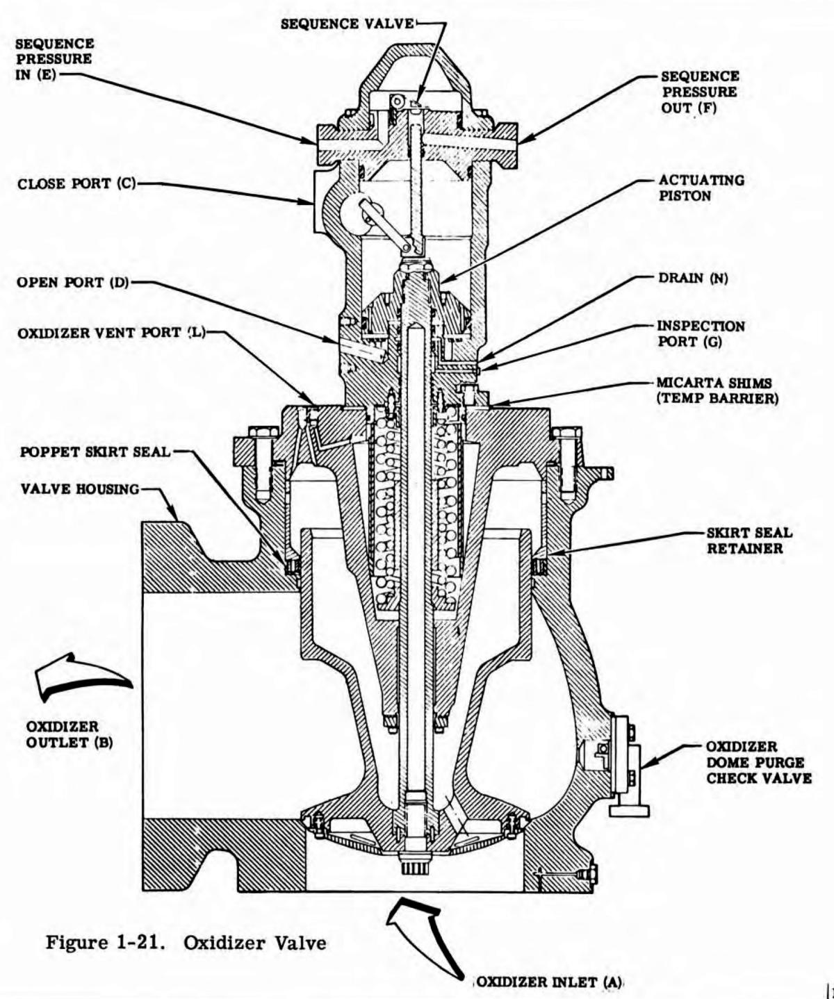
Main Oxidizer Valves
The F-1 had two identical oxidizer valves that directed LOX to the thrust chamber and hydraulic control opening fluid to the gas generator control valve. The oxidizer valves were hydraulically actuated, spring-loaded closed, pressure-balanced, fail-to-the-run position, poppet-type valves having quick response and low delta-P operating characteristics. An integral part of each oxidizer valve, and mechanically opened by this valve, was a normally closed sequence valve that, in the open position, directed hydraulic control fluid to the opening port of the gas generator control valve.
The oxidizer valves were designed so that when it was in the open position, at rated engine oxidizer pressure and flowrate, they would not close if hydraulic control fluid opening pressure was lost. Each oxidizer valve consisted of a housing that contained the oxidizer inlet and outlet ports and the seat for the poppet seal; a poppet with a machined Teflon seal secured by a seal retainer; a cover that attached to the valve housing and contained the two poppet-closing springs and also served as a mount for the cylinder and a guide for the piston rod; a cylinder, within which the actuating piston operated, that contained the open and closed actuator ports and supported the position indicator drive shaft; a cylinder head that contained the sequence valve inlet and outlet ports, along with a mount for the sequence valve gate; and a tapered piston rod that connected the actuator to the poppet, mechanically opened the sequence valve, and actuated the position indicator.
The sequence valve was a spring-loaded gate valve that seated against, and was hinged to, the oxidizer valve cylinder head. The sequence valve was offseated by the piston rod to direct opening hydraulic control fluid to the gas generator control valve when the oxidizer valve reaches 16.4% of its open position. The position indicator consisted of a rotary-motion variable resistor and open/closed position switches. The position indicator was mounted on the oxidizer valve cylinder and was coupled to the indicator drive shaft, which was mechanically linked to the piston rod. The position switch provided relay logic in the engine electrical control circuit, and the variable resistor provided instrumentation for recording valve poppet movement.
Each oxidizer valve incorporated an oxidizer dome purge check valve to admit gaseous nitrogen downstream of the valve poppet to purge the thrust chamber oxidizer dome. The check valve was a gate-type valve, spring loaded to the closed position, and allowed flow in one direction when the differential pressure across the valve exceeded 5. 0 psi. Five types of seals were used in the oxidizer valve: machined Teflon seals, Mylar lip seals, Teflon-coated steel Naflex seals, and Buna-N O-rings.
 Main Fuel Valve |
Main Fuel Valves
The F-1 had two identical fuel valves that directed fuel to the thrust chamber. The valves were hydraulically operated, spring-loaded-closed, pressure-balanced, fail-to-the-run-position, poppet-type valves having quick response and low delta-P operating characteristics. The fuel valve was designed so that when it was in the open position, at rated engine fuel pressure and flowrate, it will not close if hydraulic control fluid opening pressure was lost.
Each fuel valve consisted of a housing containing fuel inlet and outlet ports, closing and opening ports, a drain port, a purge port, a poppet seal seat and retainer, a spring-loaded poppet with a machined Teflon seal secured by a seal retainer, an actuator guide internally drilled to provide the open port passage, and a piston that connected to the poppet. The nose seal retainer incorporated 12 radially drilled passages to direct fuel into the balance cavity during the last portion of valve closing travel. This feature assists the valve in closing by maintaining a positive fluid pressure within the balance cavity. A position indicator was attached to the valve housing and recessed into the piston shaft. The indicator consisted of a linear-motion variable resistor and open and closed position switches. The position switches provided relay logic in the engine electrical control circuit, and the variable resistor provided instrumentation for recording valve poppet movement. Three types of seals were used in the fuel valve: machined Teflon seals, Viton-A O-rings, and Buna-N O-rings.
High Pressure Ducts
High-pressure ducts contained and distributed propellants separately to each of the main valves and also provided support for the turbopump forward end. The ducts were constructed of drawn aluminum tubing, bent in a continuous section. This design provided flexibility to compensate for expansion, contraction, and vibration. Each duct required a custom spacer at each end, which was machined for a specific engine fit-up and were not interchangeable. On engines incorporating MD137 change, the custom spacers were replaced with selective spacers machined to various dash number sizes. The No. 2 oxidizer high-pressure ducts provided a tap-off flange for the gas generator oxidizer duct.
The No. 1 fuel high-pressure duct provided tap-offs for the bearing coolant control valve, gimbal filter manifold, igniter fuel valve, and fuel high-pressure duct drain quick-disconnect. The No. 2 fuel high-pressure duct provided tap-offs for the gas generator fuel duct, engine control valve, No. 2 fuel bleed and fuel high-pressure duct drain quick-disconnect.
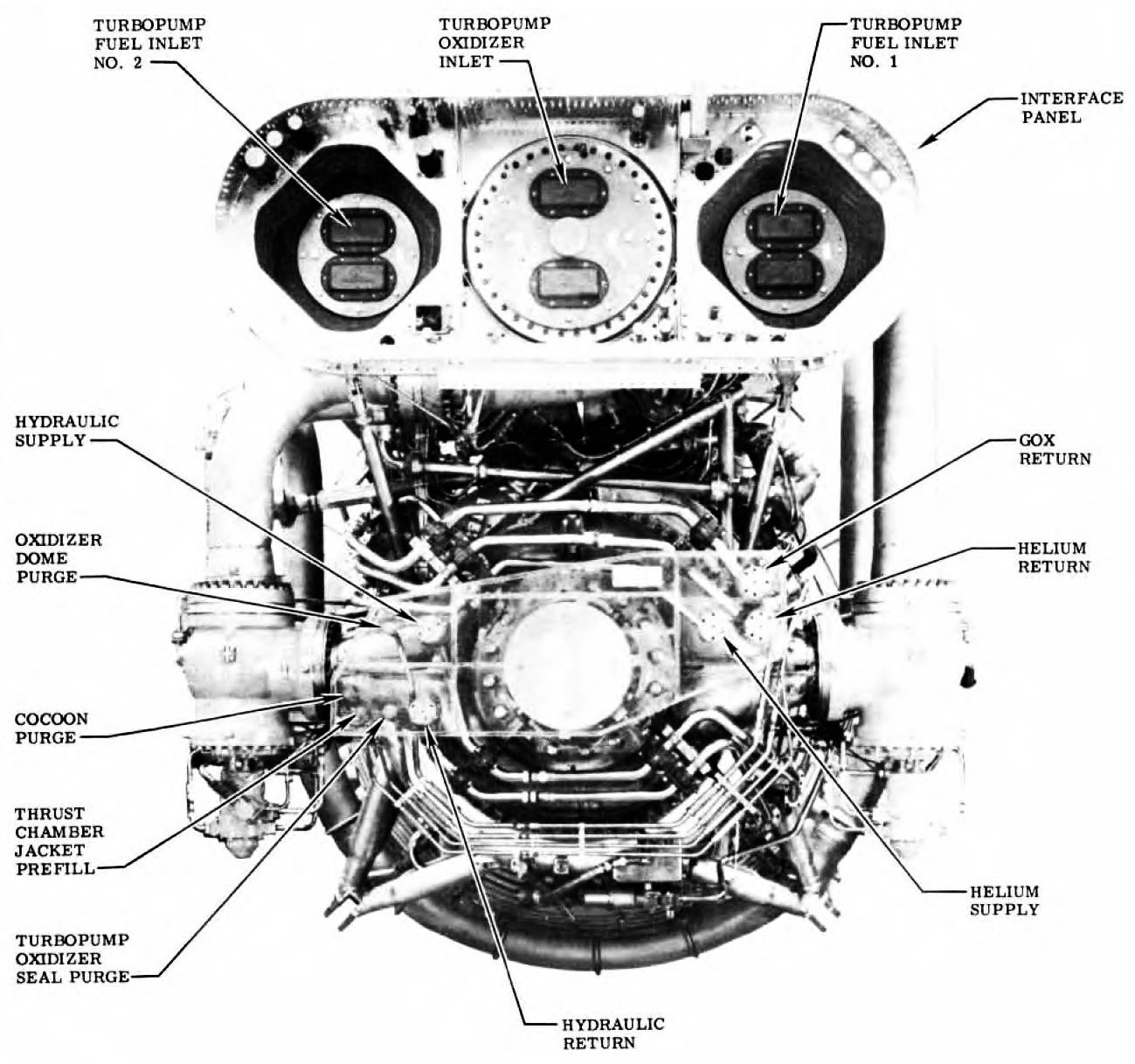
Engine Interface Panel
The engine interface panel was mounted above the turbopump oxidizer and fuel inlets. The panel provided electrical and fluid connect locations between the engine and the vehicle, as well as attach points for thermal insulation blanket brackets.
Ignition System
 Top: Hypergolic Igniter Bottoom: Pyrotechnic Igniter |
Five igniters were required for each engine start: two pyrotechnic igniters for the gas generator, two pyrotechnic igniters for the thrust chamber nozzle extension, and a hypergol igniter for the thrust chamber. The pyrotechnic igniters were electrically fired by 500 VAC signal, initiated gas generator combustion, and reignited the fuel-rich gas generator exhaust gas in the nozzle extension. The hypergol igniter initiates thrust chamber combustion when fuel pressure from the No. 1 fuel high-pressure duct ruptures the hypergol igniter diaphragms and forces pyrophoric fluid into the thrust chamber through the injector igniter fuel orifices.
Two pyrotechnic high-voltage igniters were installed in the gas generator combustor inlet flange igniter bosses. Two more igniters were installed in nozzle extension bosses near the 11:1 expansion ratio plane. The igniter external structure consisted of a metal tube crimped and soldered at one end into a receptacle with four electrical contact pins. The opposite end of the tube was sealed with a disc of silver alloy foil. Internally, the igniter had two plastic sleeves, a dual-element squib assembly, a main pyrotechnic charge, a diode, and the wire required to connect the two igniter circuits to the four receptacle pins. When a 500 VAC electrical stimulus was impressed on the igniter circuit, the diode was triggered allowing a nominal 4.5 amperes of current to flow and ignite the squib. The flame and hot particles from the squib ignited the main pyrotechnic charge. The burning of the main charge severed the link wire imbedded in the charge within 200-800 milliseconds and continued burning for 6.5 to 9.5 sec. Severing of the igniter link wire provided a positive signal to the engine electrical control system that the igniter has functioned correctly. When 250 VAC or less was impressed on the squib circuit, the diode prevented current flow and the igniter did not fire.
The hypergol igniter contained a pyrophoric fluid that produced initial combustion in the thrust chamber. The igniter was installed in the hypergol manifold by a threaded cap secured by a lockpin. The igniter consisted of a cartridge, a plug, a cap, and related seals. The cartridge contained 403 ±10 grams of pyrophoric fluid consisting of 85% triethylborane and 15% triethylaluminum. Two burst diaphragms were welded to the cartridge, one at each end, to contain the pyrophoric fluid within the cartridge. The burst diaphragm at the cap end of the igniter was identified as the downstream diaphragm and had a burst pressure of 350 (+25, -75) psig. The upstream diaphragm had a burst pressure of 500 (+25, -75) psig. The hypergol igniter was approximately 18" in length and 2.375" inches in diameter.
Gas Generator
 Gas Generator Combustor |
 Gas Generator Ball Valve |
The gas generating system provided the internal power required to operate the engine. Utilizing tank-head pressure from the vehicle, the gas generating system developed sufficient power to start the engine and raise its power level to rated power by using a portion of its own output (bootstrapping). The internal power was generated by tapping propellants from the high-pressure ducts and directing them to the gas generator where hot gas was produced to power the turbopump. After impacting the two-stage turbine, the gas was further utilized by a heat exchanger where additional heat was extracted to condition the gases used for vehicle tank pressurization. The now relatively cool gas generator exhaust gas was directed into the lower section of the thrust chamber to provide film cooling of the double-wall portion of the nozzle. Orifices in the propellant ducts to the gas generator controlled the system power level to provide a constant mass flowrate to the thrust chamber, thereby insuring a constant thrust output.
The gas generator occupied an 18" x 24" x 28" envelope and weighed approximately 220 lb. It included a dual ball valve, an injector fuel inlet housing tee, an integral oxidizer dome and injector, and a combustor. Six types of seals were used in the gas generator: silver-plated stainless-steel Naflex and K-seals and copper crush washers for hot-gas applications, Teflon-coated steel K-seals for cryogenic applications, and Buna-N O-rings for fuel applications.
The gas generator ball valve was a hydraulically operated valve incorporating two hollow balls connected to a single actuator. The balls were shells on shafts, each shell having an inlet and outlet flow passage. The inlet and outlet flow passages were located diametrically opposite each other in the oxidizer ball and 150° apart in the fuel ball. A tube was welded between the inlet and outlet passages in the fuel ball to reduce flow resistance. Both balls seated against bellows-type seals. The fuel bellows seal incorporated a deflection elbow for the fuel outlet that was contoured to reduce pressure drop in the gas generator fuel system. Both ball shafts rotated on roller bearings, and each ball also rotated against the actuator housing on roller bearings and races. A linear-motion position switch and an integral electrical connector were mounted in the valve cover, which also sealed the switch compartment. The ball valve oxidizer outlet attached directly to the gas generator injector oxidizer inlet. The gas generator fuel inlet housing tee connected the ball valve outlet to the injector fuel inlet. The gas generator ball valve opening was directed by sequence valves on the oxidizer valves. Hydraulic fluid recirculated through a warmant passage in the fuel ball housing, preventing the fuel in the fuel ball housing from freezing, and through a passage in the piston between the opening port and the closing port, preventing air entrapment and hydraulic fluid freezing. Four types of seals were used in the gas generator ball valve: machined Kel-F seals, Kel-F lip seals, Buna-N O-rings, and a Teflon-coated steel Naflex seal.
A port to measure or vent seal leakage past the seal between the injector and combustor was also located on the combustor inlet flange. The combustor outlet flange, which was the attach point for the turbine manifold, incorporated two ports (90° apart) to monitor gas pressure and one port to vent or measure seal leakage past the seal at this interface. Combustor wall temperatures were held to safe operating limits by the combination of film coolant provided by the outer fuel ring of the injector, and the fuel-rich mixture ratio with which the gas generator operates.
The gas generator injector was a flat-faced, multi-orificed-type injector incorporating a dome, a plate, a ring manifold, five oxidizer rings, five fuel rings, and a fuel disk. The injector was mounted on the combustor, and the gas generator ball valve and the gas generator fuel inlet housing tee were mounted on the injector. The injector directed fuel and oxidizer into the gas generator combustor. Fuel entered the injector through the gas generator fuel inlet housing tee from the gas generator ball valve. Fuel was directed through radial passages in the plate and injected into the combustor through orifices in the five fuel rings and the fuel disk. Oxidizer entered the injector through the oxidizer inlet manifold from the gas generator ball valve. The oxidizer was directed from the oxidizer manifold through internal passages in the plate and was injected into the combustor through the orifices in the five oxidizer rings. The injector uses a double-orificed pattern in which the fuel and oxidizer rings were drilled in a pattern and angle so that the stream from one oxidizer orifice will impinge upon the stream from another oxidizer orifice, and the stream from a fuel orifice will impinge upon the stream from another fuel orifice. Orifices in the outer fuel ring also provide a cooling film of fuel for the combustor choke ring wall.
The gas generator combustor was a welded single-walled manifold connecting the gas generator injector and the turbine inlet. The combustor contained a chamber for burning propellants and for exhausting the gases from the burning propellants into the turbopump turbine manifold. The combustor was thermally insulated by a sheet metal shell that bolted around the combustor body. The inlet flange was the attach point for the injector and dome assembly and incorporateed a 45° lip section that deflected the flame pattern to the bottom section of the combustor. Also incorporated in the inlet flange were the two bosses (45° apart) for pyrotechnic igniter installation and two ports (150° apart) to monitor gas pressure. A port to measure or vent seal leakage past the seal between the injector and combustor was also located on the combustor inlet flange. The combustor outlet flange, which was the attach point for the turbine manifold, incorporated two ports (90° apart) to monitor gas pressure and one port to vent or measure seal leakage past the seal at this interface. Combustor wall temperatures were held to safe operating limits by the combination of film coolant provided by the outer fuel ring of the injector, and the fuel-rich mixture ratio with which the gas generator operated.
The gas generator oxidizer duct contained and distributed oxidizer from the No. 2 turbopump oxidizer outlet duct to the gas generator ball valve oxidizer inlet. The gas generator oxidizer duct was a two-piece, 1.50" ID duct incorporating three bellows-connected gimbal joints to allow flexing to accommodate installation tolerances and thermal expansion or contraction of the duct. The gas generator oxidizer duct incorporated two orifices for oxidizer flowrate calibration. One orifice was installed at the interface of the gas generator oxidizer duct and the No. 2 turbopump oxidizer outlet duct, and the other orifice was installed at the interface of the two gas generator oxidizer duct sections. Both orifices were sized at engine acceptance test. A fluid scoop, which extends into the fluid stream of the No. 2 turbopump oxidizer outlet duct, was installed at the interface of the gas generator oxidizer duct and the No. 2 turbopump oxidizer outlet duct.
The gas generator fuel duct contained and distributed fuel from the No. 2 turbopump fuel outlet duct to the gas generator ball valve fuel inlet. The gas generator fuel duct was a one-piece, 2.25" ID duct incorporating three bellows-connected gimbal joints to allow flexing to accommodate installation tolerances, thermal expansion, and contraction of the duct. The gas generator fuel duct incorporated an orifice for fuel flowrate calibration. The orifice was installed at the interface of the gas generator fuel duct and the No. 2 turbopump fuel outlet duct and sized during the engine acceptance test. A flow deflector was installed at the interface of the gas generator fuel duct and the gas generator ball valve fuel inlet.
Heat Exchanger
 Heat Exchanger (heriocrelics.org) |
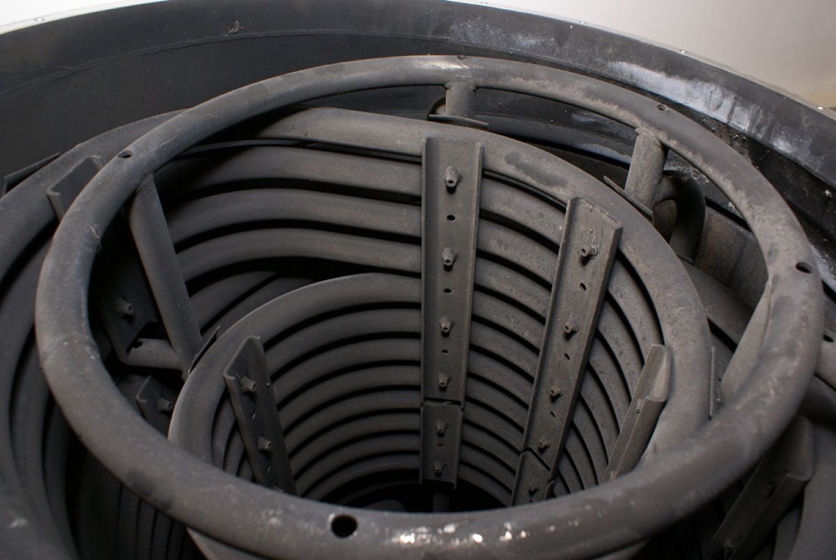
The heat exchanger was 43" in diameter and 58" long, with the diameter varying from 40" at the turbine outlet to 24" at the turbine exhaust manifold. Hot gases from the turbine were directed to the heat exchanger where a portion of the heat was transferred to oxidizer and helium coils. In the heat transfer, oxidizer in the coils was converted to GOX for vehicle oxidizer tank pressurization, and the chilled helium in the coils was expanded for vehicle fuel tank pressurization. The heat exchanger upper section enclosed the helium coils along with helium and oxidizer supply and return line mounting flanges. Each flange had ports to measure seal leakage. The supply ports incorporated orifices to control the flow of oxidizer or helium through the coils. The lower section of the heat exchanger enclosed the oxidizer coils and contains a bellows assembly to compensate for thermal expansion during engine operation. Tubular structural members, clamped to the coils and welded to brackets incorporated in the heat exchanger body, secured the oxidizer coils. Heat exchanger connections at the turbine outlet manifold and the thrust chamber exhaust manifold were sealed by pressure-actuated Naflex seals.
Engine Control System
 Engine Control and Redundant Shutdown Valves |
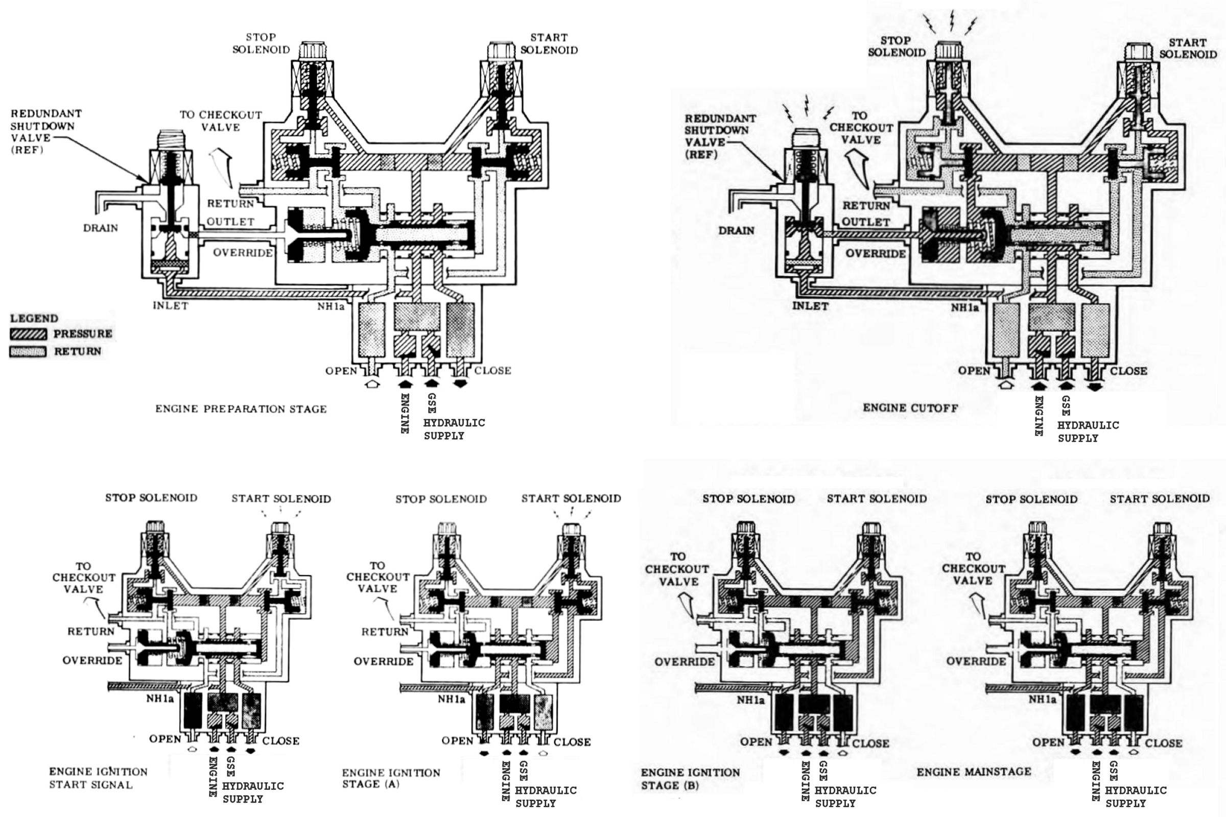
The engine control system regulated engine operation by directing, governing, and sequencing engine propellant valve activity during the start, transition, mainstage, and cutoff phases of engine operation. The engine control valve, redundant shutdown valve, checkout valve, and hypergol manifold assembly comprised the control system. Orifices in the engine control system controlled propellant valve timing.
The engine control valve directed hydraulic fluid to open and close the propellant valves and the gas generator ball valve. The engine control valve was electrically controlled and hydraulically actuated, with an internal hydraulic lockup that maintained actuation when the start signal was removed. The valve included an override piston to deactuate the valve in case of stop solenoid failure. The assembly consisted of a control section and a filter manifold section.
The control section had two solenoid-operated pilot (start and stop) valves, two slaved poppet valves, a matched selector spool and sleeve, a stop actuator, an override piston, and a valve body. The solenoid-operated pilot valves were identical except the start solenoid electrical connector has two pins and the stop solenoid has three pins to prevent improper connection. To ensure that the engine could not be started with the stop solenoid disconnected, the negative lead of the start solenoid was wired in series with the negative lead of the stop solenoid. Each solenoid valve consisted of a coil, a double-acting poppet (the armature), and two poppet seats (upstream and downstream). The coil was energized by 24-30 VDC. The poppet was spring loaded against the downstream seat. Each solenoid valve was protected by a 10-micron filter at its inlet passage. A passage in the control valve body directed fluid to a passage that directed fluid to the poppet cavity. Two passages permitted fluid flow from the cavity to the slaved pilot valve cylinder when the poppet was deenergized. The downstream seat formed the base of the valve assembly and contained a passage that was closed by the deenergized poppet and opened when the poppet was energized.
Two slaved pilot valves, each slaved to its respective solenoid pilot valve, directed fluid to shuttle the selector spool. Each slaved pilot valve consisted of a poppet, two identical poppet seats, a piston, a cylinder, and a spring. The poppet was a pressure-actuated disc that free-floated between the two poppet seats. Both faces of the poppet were finished to provide a metal-to-metal seal with the poppet seats. The poppet seats, separated by a spacer, were installed face-to-face on both sides of the poppet. At start, momentary off-seating of the poppet from the normal position allowed hydraulic pressure to shuttle the selector spool to open. The cylinder housed a piston and spring and was ported to admit hydraulic pressure to the spring cavity when the solenoid pilot valve was deenergized. When the start solenoid was energized, the piston was momentarily actuated through the force transmitted to the piston shaft by the poppet.
The selector valve was a matched spool and sleeve. The spool, floating inside the sleeve, was a hollow, closed-end cylinder with three ports and two sealing lands. The spool was actuated from its normal spring-loaded position (closed) by fluid pressure by the momentary actuation of the slaved pilot valve at start. Once actuated, the spool was hydraulically locked by fluid pressure from the open port. The sleeve had three ports that align with three annular passages in the selector valve cavity. Four O-rings with Teflon backup rings prevented leakage between the annular passages. A threaded retaining cap held the selector valve in its cavity and provides a mechanical stop for the spool.
The stop actuator was a spring-loaded, hydraulically actuated piston that positioned the selector spool to the closed position. The actuator was normally controlled by the stop slaved pilot valve but could be directly actuated by the override piston in case of stop valve failure. Four holes admitted control fluid into the spring cavity from an annular passage supplied from the stop slaved pilot valve. The override piston was hydraulically actuated and mechanically coupled to the stop actuator. The piston was used to position the selector spool in case of stop valve failure. An external pressure source was required to actuate the piston, which mechanically positions the selector spool to the closed position. The piston was held deactuated against a stop by a coil spring. The stop retained the override piston in its cavity and incorporated the override pressure inlet port. The control valve body housed the operational units and bolts to the filter manifold assembly. The interface of valve body and filter assembly was sealed by a seal plate.
The filter manifold was the supply filtration and distribution point for all control system fluid. The filter manifold consisted of two swing-gate check valves, three filters, and a manifold body. The check valves were flange mounted back-to-back in a common supply cavity. One check valve covered the GSE SUPPLY fluid inlet port, and the other check valve covered the ENG SUPPLY fluid inlet port. Three 25-micron wire-mesh filters were installed in the manifold assembly. One filter was in the supply system and one each in the opening and closing passages. The manifold body houseed the filters and was bolted to the control valve body. Two threaded ports in the ENGINE/GSE filter supply cavity provided pressure for instrumentation and for the emergency override system. Passages connected the closed, open, and supply filter cavities to corresponding ports of the control section. Three types of seals were used in the engine control valve: Viton-A O-rings for plug and bleeder seals, a Viton-A Gask-O-Seal at the manifold-to-solenoid-valves joint, and Buna-N O-rings for all other applications.
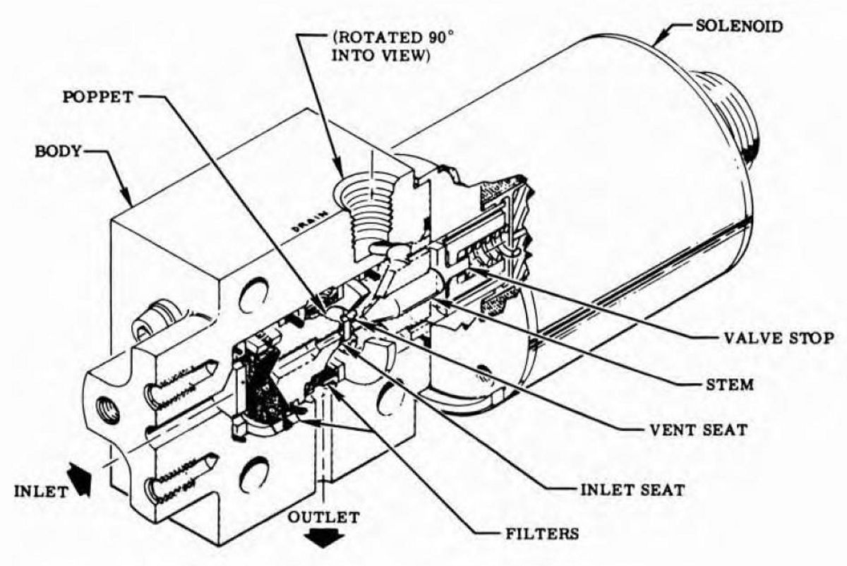 Redundant Shutdown Valve |
The redundant shutdown valve was a solenoid-operated, normally closed, three-way valve incorporating two 10-micron filters (one disk shaped, the other cylindrical), fixed inlet and vent seats, and a floating poppet that was spring loaded to the closed position against the inlet seat. The valve directed hydraulic pressure to the engine control valve override pressure port as a redundant means of effecting engine shutdown in case of failure of the engine control valve stop solenoid, and to provide a drain for the override pressure port during engine checkout and operation. Continuous application of 24-30 VDC was required to keep the valve energized. The energizing signal input was applied simultaneously to the redundant shutdown valve solenoid and the engine control valve stop solenoid at engine cutoff. The redundant shutdown valve body provided an internally threaded DRAIN port and flanged IN and OUT ports. The solenoid electrical connector was a four-pin connector with only three of the pins used. Pin A was used for the positive energizing signal input, pin B for the negative return signal, and pin C for monitoring the signal received at the solenoid. Pins A and D were bussed internally within the connector. The seals used in the redundant shutdown valve were Buna-N O-rings.
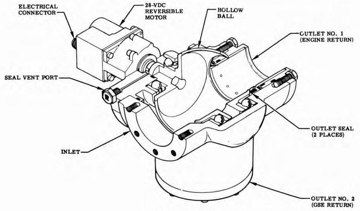 Check Out Valve |
The 8" x 9" x 14" checkout valve was located just below the engine control valve on the No. 2 side of the engine thrust chamber jacket. The checkout valve was a motor-driven selector valve that directed engine control return fluid back to the GSE or engine supply source. The checkout valve consisted of a ball, a three-port housing, and an actuator. The actuator was a 24-30 VDC reversible motor that incorporated reduction gearing, position switches, and limit switches. The actuator controlled the position of the ball to direct control fluid from the inlet port to one of the outlet ports. During engine checkout or servicing, the checkout valve ball was positioned so that fuel entering the inlet port was directed through the ball and out the GSE return outlet No. 2 port. For engine static firing or flight, the ball was positioned so that fuel entering the inlet port was directed through the ball and out the engine return outlet No. 1 port. Three types of seals were used in the checkout valve: Viton-A O-rings for dynamic applications, Buna-N O-rings for static applications, and machined Teflon seals for the ball seals.
 Hypergol Manifold |
The hypergol manifold assembly sequenced engine operation from ignition stage into mainstage. The assembly was attached to a bracket located on the thrust chamber fuel manifold and consisted of a hypergol cartridge container, an ignition monitor valve, an igniter fuel valve, and a hypergol installed switch. Only the hypergol cartridge container and hypergol installed switch were replaceable components. The hypergol container was a cylindrical manifold into which the hypergol cartridge was installed. The hypergol installed switch was a cam-actuated switch that indicated the installed position of the hypergol cartridge.
The igniter fuel valve, an integral part of the hypergol manifold assembly, was opened by fuel pressure applied to the hypergol manifold FUEL INLET port from the No. 1 fuel outlet duct. When the igniter fuel valve was opened, an internal passage in the manifold directed fuel from the igniter fuel valve to the hypergol container where the fuel first ruptured the hypergol cartridge diaphragms and then followed the hypergolic fluid into the thrust chamber for ignition. A Teflon O-ring in the poppet nose seated against a seat machined into the hypergol manifold body. The desired spring loading was obtained by shimming the spring.
 Ignition Monitor Valve |
The ignition monitor valve directed fuel valve openings only after satisfactory thrust chamber ignition had been achieved. The ignition monitor valve was a spring-loaded, pressure-actuated, fail-to-the-run, three-way valve mounted on the hypergol manifold and actuated by ignition combustion pressure. A dual-faced, spring-loaded poppet directed valve opening pressure to the fuel valves when ignition combustion pressure, acting on a laminated Mylar diaphragm, shuttled the poppet to the valve's open position. Once shuttled, the valve remained in the open position until engine shutdown due to differential pressure across the upstream and downstream faces of the poppets. Teflon Viton-A "slipper" seals and Buna-N O-rings were used in dynamic and static seal applications. An internal orifice between the inlet and outlet ports permitted fluid recirculation to bleed air from the control fluid. A mechanical lockup, actuated through a cam-rod that was positioned to cam the follower when an unruptured hypergol cartridge was installed, prevented ignition monitor valve actuation until the hypergol cartridge has ruptured. The atmospheric reference port was vented to the fuel overboard drain system.
Flight Instrumentations System
The flight instrumentation system monitored engine performance during checkout, test, and vehicle flight operations. The system consisted of pressure transducers, temperature transducers, position indicators, a flow measuring device, power distribution junction boxes, and associated electrical harnesses. The basic flight instrumentation system was composed of a primary and an auxiliary system. The primary instrumentation system included parameters critical to all engine static firings and subsequent vehicle launches; the auxiliary system was used during research, development, and acceptance test portions of the engine static-test program and initial vehicle flights. Eight types of seals were used in the flight instrumentation system installation: asbestos rubber sheet gaskets for electrical connector application; Viton-A O-rings and Gask-O-Seals for fuel applications; copper crush washers, copper-plated nickel-base Naflex seals, gold-plated steel K-seals for hot-gas applications; and Teflon-coated steel Naflex and K-seals for cryogenic applications. There were two electrical junction boxes in the flight instrumentation system: a primary junction box located in the primary system and the auxiliary junction box located in the auxiliary system. On engine incorporating MD96 change, the auxiliary junction box was deleted. The junction boxes served as junction points for signal circuitry of respective transducers either to and from the telemetry and instrumentation system during vehicle flight or to and from the control center during engine static test. The primary junction box had provisions for eight electrical connections; the auxiliary junction box has provisions for five electrical connections. Both junction boxes were hermetically sealed to prevent possible entry of contaminants and moisture.
 Pressure Transducer |
Flight instrumentation pressure transducers were DC input, DC output, absolute pressure transducers consisting of a mechanical force summing element coupled to an electrical bridge. The electrical bridge output was directly proportional to the pressure applied to the mechanical-force summing network. All four of the bridge elements in the transducer were active. For each bridge element that increased impedance with increasing pressure, a second bridge element decreases impedance with increasing pressure. These elements were connected into the bridge in such a way as to obtain maximum sensitivity from the bridge. The transducer also contained the necessary circuit elements to isolate the output from the input, to provide a regulated bridge excitation voltage, to provide all necessary bridge amplification, to provide bridge output demodulation if required, and to provide all required output filtration so that the transducer can be excited with a nominal 28 VDC input and provide a 5 VDC output at full pressure range. The transducer simulated the output at 20% and 80% operating range. These simulation steps were activated by applying 28 VDC pins E and F for the 20% and 80% points, respectively. The application of this voltage activated a switching circuit that substitute a resistor in the bridge network, thereby simulating the bridge output for 20% or 80% of the instrument pressure range. The transducer uses a six-pin connector with the following pin functions:
Pin A, positive excitation (+28VDC); Pin B, positive output (+5 VDC at full range pressure); Pin C, output return; Pin D, excitation return; Pin E, 20% calibration (+28VDC); Pin F, 80% calibration (+28VDC).
 Temperature Transducer |
Flight instrumentation temperature transducers were of the platinum resistance type. All of the resistance bulbs had a three-wire termination that allowed a bridge completion with a transmission line in opposite bridge legs, thereby making zero and sensitivity changes negligible with respect to variations in line length and resistance. Each transducer was supplied with its own resistance-versus-temperature calibration over a specified range. While all of the transducers operated on the same principle and the electrical connections were identical, the physical configurations of the various transducers differed with the installation and measurement requirements. Engines incorporating MD159 change had an improved cocoon temperature transducer with glass-insulated and resistance-welded lead wires enclosed in a platinum tube and a sensing element protected by a shield.
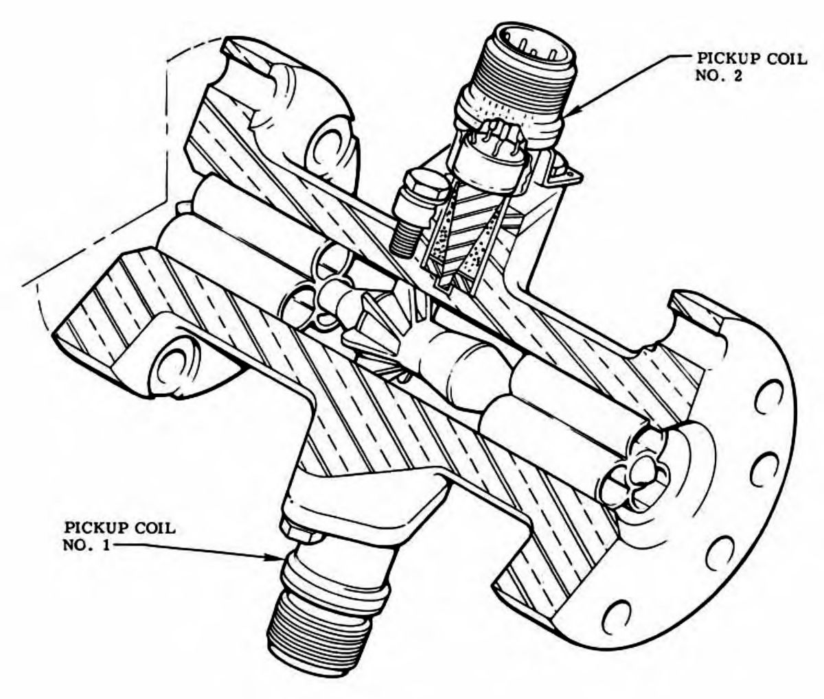 LOX Flowmeter |
The oxidizer flowmeter was a turbine-type, volumetric, liquid-flow transducer that measured the flow of oxidizer entering the heat exchanger coil. It was mounted between the heat exchanger check valve and the oxidizer inlet line. It consisted of a rotor assembly that sensed the oxidizer flow, flow straighteners that directed the flow of oxidizer across the rotor, and two pickup coils. The pickup coils were enclosed, moisture-proof units with electrical receptacles. Each coil was electrostatically shielded, potted and contained an auxiliary isolated coil for checkout purposes. The flow of oxidizer through the flowmeter set the rotor in motion. The angular speed of the rotor was a function of the oxidizer volumetric flowrate and was detected by the magnetic pickup.
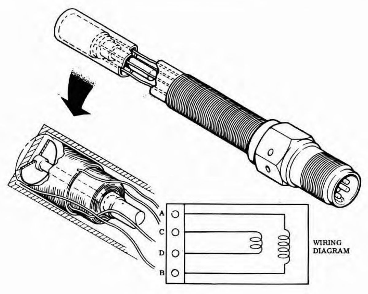 Speed Transducer |
The flight instrumentation speed transducer used a magnetic pickup to sense turbopump speed. The assembly consisted of a probe section that housed the pickup coils, an adapter section (welded between the probe and electrical receptacle) that was threaded to allow installation of the unit into the turbopump torque gear housing, an electrical receptacle, and a pickup coil that served as a pulse generator. When the transducer installed, the probe tip aligned with the two-hole tachometer on the turbopump torque gear sleeve. As the turbopump shaft rotated and each hole passed the tip of the probe, the pickup coil flux density changed. The buildup and collapse of the flux lines generated a voltage across the leads. This voltage, proportional to the pump shaft speed, was then conditioned for recording. The magnitude of the voltage was dependent on the angular speed of the turbopump shaft, the distance between the pickup coil and torque gear sleeve, and the medium of the gap. The frequency was determined by the angular speed of the pump shaft, and the number of holes in the torque gear sleeve.
Thermal Insulation
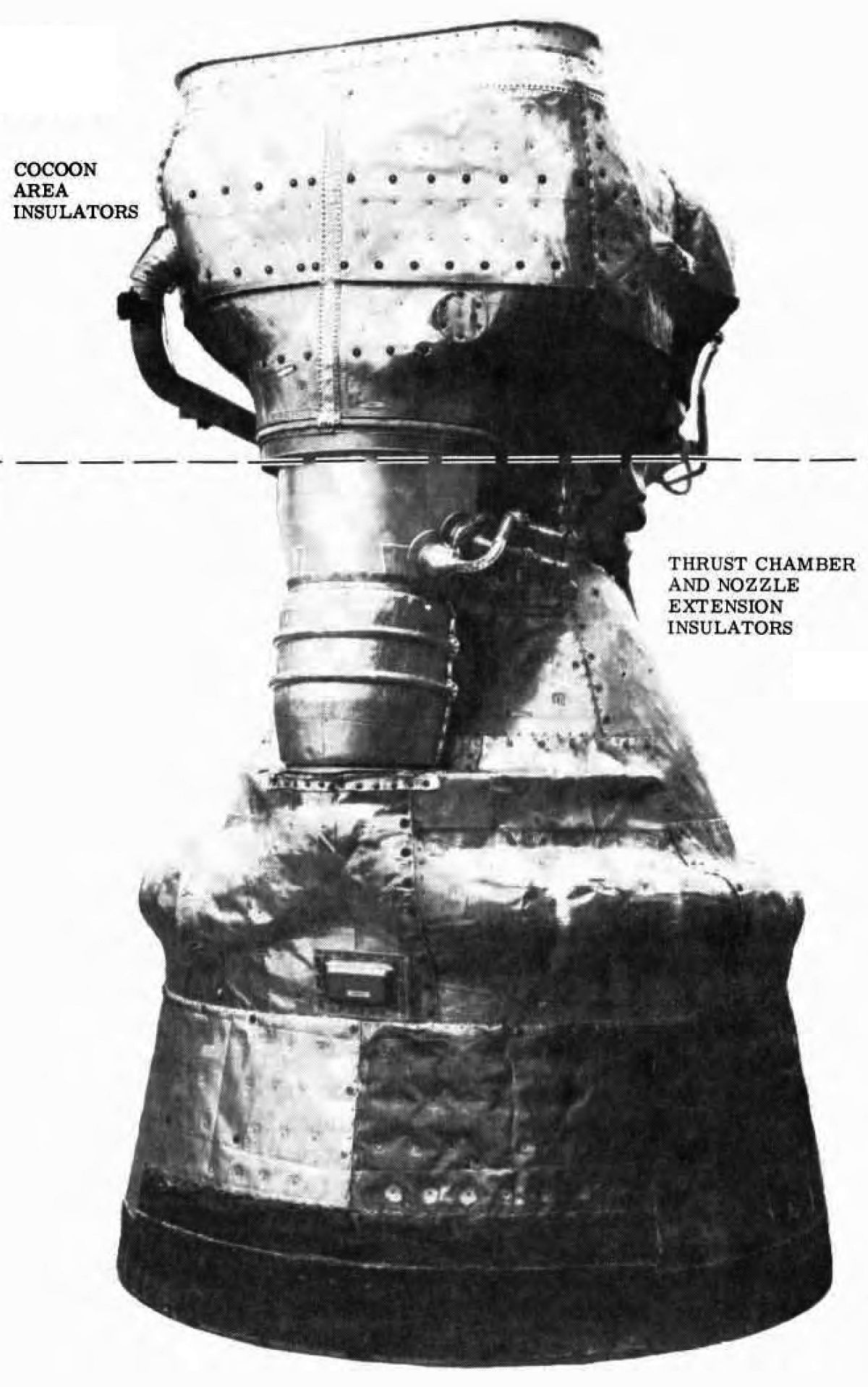 F-1 with TIS |
Thermal insulation system (TIS) protected the engine from extreme temperatures caused by plume radiation and back-flow during vehicle flight. Engine thermal insulators were of two types, foil-batt and asbestos blanket. Foil-batt insulators were preformed segments constructed of random fiber batting secured between two layers of textured inconel foil. The thrust chamber insulator inner foil thickness was 0.004"; outer foil thickness was 0.006". Cocoon insulator foils were 0.006" thick. The cocoon insulator inner foil was vented to prevent ballooning due to expansion of gases trapped between the layers of foil. These insulators were used to cover large, flat areas of the thrust chamber and nozzle extension, heat exchanger lines and bellows, connection lines, and the cocoon area (thrust chamber throat to interface panel). Asbestos blanket insulators were composed of multiple layers of asbestos cloth reinforced with Inconel lockwire and coated on one side with aluminum. The asbestos blankets were laminates of two, four, or five layers, depending on the location on the engine. Asbestos blankets were used on the exit end of the nozzle extension, above the oxidizer dome between the gimbal bearing and interface panel, and below the cocoon between the thrust chamber and turbine manifold. Hardware that secured the thermal insulation to the engine consisted of support structure, screws, self-locking nuts, flat washers, nut clips, bolts, and Inconel lockwire. Support structure (brackets, straps, and supports) was located primarily in the cocoon area. Protruding studs were percussion welded onto hatbands of the thrust chamber to support and secure insulator panels. Brackets with nutplates were provided to secure insulator panels to the nozzle extension.
Engine Purge and Drain System
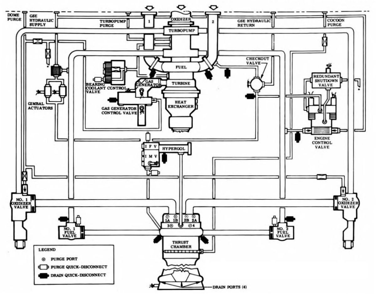 F-1 with TIS |
The engine purge and drain system provided a means of inhibiting contamination in the engine critical areas and permitted safe disposition of expended coolant fluids, residual propellants, and seal leakage fluids. The engine purge system and the drain system were each divided into a service mode system and an operational mode system.
The service mode drain system helped drain residual fuel and control system fluid from the engine during maintenance and post-test. This system consisted of quick-disconnect fittings and drain plugs located at propellant feed and control system low points. These fittings were located on the No. 1 and No. 2 fuel inlet elbows, No. 1 and No. 2 high-pressure fuel ducts, thrust chamber fuel inlet manifold, hypergol manifold, and gas generator. Quick-disconnect fittings for draining the control system fluid were located on the control system engine return line, control system engine supply line, and gimbal actuator return line. Four drain plugs located on the thrust chamber fuel return manifold permit the thrust chamber tubes to be drained of residual fuel, prefill fluid, or flushing solvent.
The operational mode drain system dumped fluid that leaked past internal seals and expended turbopump bearing coolant fluid. This system consisted of separate oxidizer and fuel overboard drain lines and a fuel drain manifold. Fuel and control fluid seal leakage, along with expended bearing coolant fluid were collected into a single fuel overboard drain line on the No. 2 side of the engine. The fuel drain manifold was the collective drain point for expended coolant fluid and excess preservative compound that remained after turbopump preservative procedures. Oxidizer leakage past the turbopump primary oxidizer seal, the No. 1 and No. 2 internal oxidizer valve seals, and gas generator control valve seals was directed to an oxidizer overboard drain line on the No. 1 side of the engine. This line also directed purge flow through the turbopump oxidizer-side intermediate seal overboard. Paralleling the oxidizer overboard drain line on the No. 1 side of the engine was the nitrogen purge overboard drain line, which directed purge flow through the intermediate seal fuel side overboard.
--- On To Part 8.13 - Operation ---
Send mail to
![]() with questions or comments about this web site.
with questions or comments about this web site.
![]()