U.S. Manned Rocket Propulsion Evolution
Part 8.13: Rocketdyne F-1 Engine Operation
Compiled by Kimble D. McCutcheon
Published 13 May 2021; Revised 3 Aug 2022
Overview
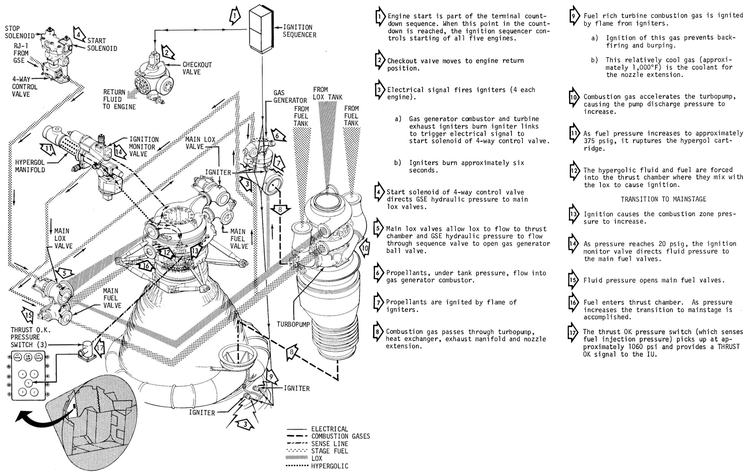
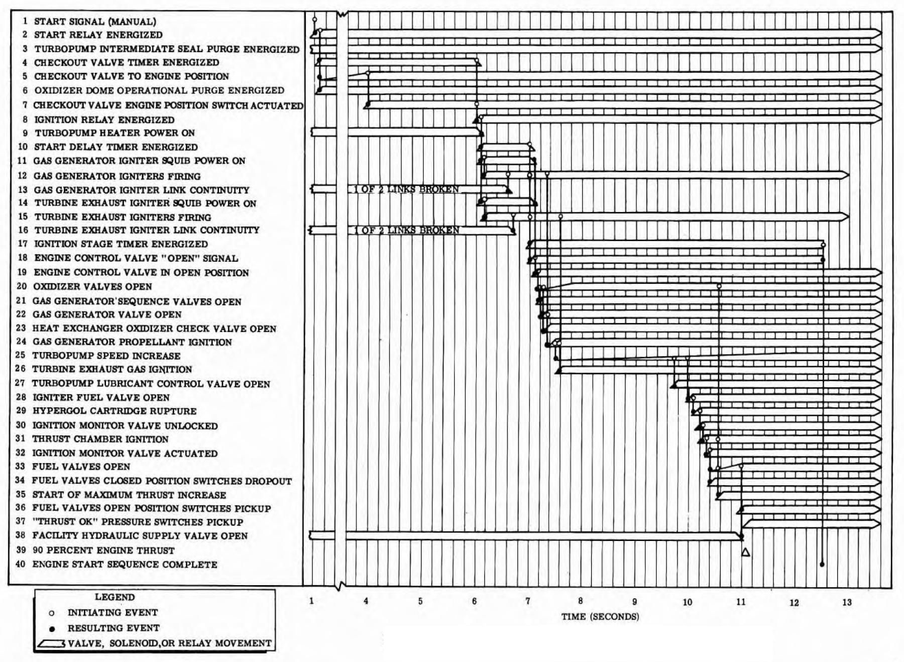
The F-1 took about five seconds to start using tank head pressure only. GSE-furnished hydraulic pressure initiated a pressure ladder start sequence that began by opening the engine control valve that then ported hydraulic fluid to open the main LOX valve, allowing LOX to flow in a way that treated the LOX impeller as a turbine and start turning the turbopump. This defeated the turbopump's breakaway torque. The gas generator valves then opened, admitting low-pressure RP-1 and LOX to the gas generator where two pyrotechnic igniters produced initial gas generator pressure and initiated gas generator combustion. In two to three seconds, gas generator pressure was sufficient to open the igniter fuel valve, which then admitted hypergolic starting fluid and starting fuel to start thrust chamber ignition. As soon as the thrust chamber ignition was sensed by another valve, the main fuel valves opened and the thrust continued to rise. The thrust chamber tubes were primed with about 104 gallons of ethylene glycol, so the initial fuel burning during this engine start transient period was an ethylene glycol and water mixture that did not provide as high a chamber pressure as straight RP-1. Once the ethylene glycol was consumed chamber pressure kept increasing until it reached 100%.Engine start and shutdown sequences were controlled by an electrical-hydraulic-mechanical system. Electrical relays in the GSE, along with solenoids and switches on the engine, were employed to start, maintain, and stop the engine during test; on-board systems performed these same functions during flight. An orificed hydraulic control system powered and sequenced the propellant and control valves. Mechanically-linked devices also assisted in sequencing propellant valve actuation. The following scenario describes F-1 operation during ground testing; flight operation was similar, but with no post-cutoff activities.
|
|
|
|
| Pictorial | Functional Flow | Timing | |
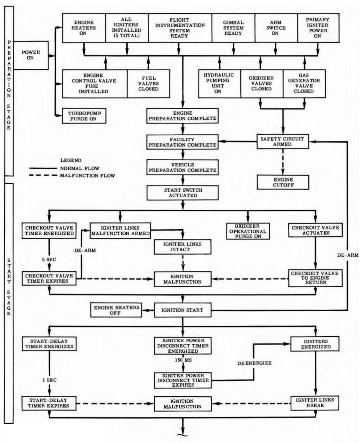
Engine Preparation Stage
The engine preparation stage was that activity during which it was determined that the engine and the test facility were in a satisfactory condition for a safe engine start. The culmination of this activity was an ENGINE PREPARATION COMPLETE signal which, in conjunction with a facility preparation complete signal, made electrical power available to the engine start switch.
 |
| F-1 Preparation Stage |
Engine Start and Ignition Stage
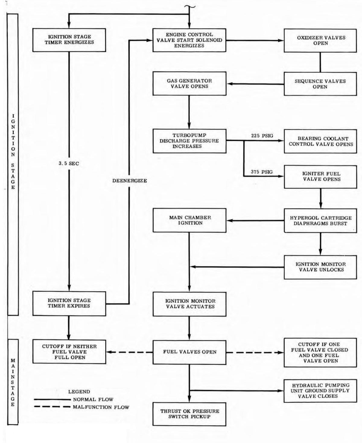
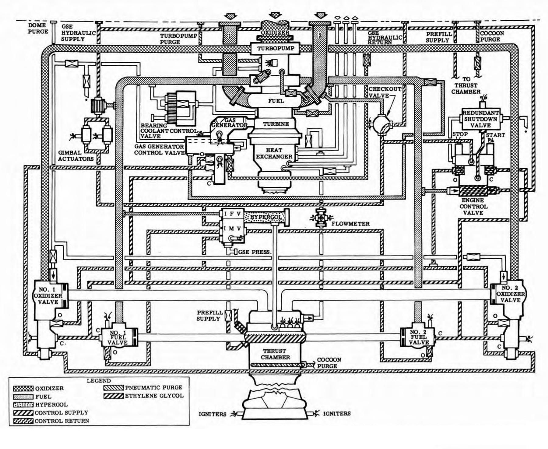
The engine start and ignition stage was initiated with the manual actuation of the engine start switch and extended through the period during which the propellant valves were opened, propellant combustion was established, and transition into mainstage took place. Engine start switch actuation electrically initiated the automatic start sequence that caused the checkout valve to rotate to the engine return position, the oxidizer dome operational purge to come on, and a checkout valve timer to energize. When the checkout valve timer expired and the checkout valve was in the engine return position, the turbopump heaters were deenergized, electrical power was applied to the gas generator and nozzle extension pyrotechnic igniters, and a start delay timer energized. When the start delay timer expired and burning of the igniters was electrically verified by the severance of igniter links, the start solenoid of the engine control valve and an ignition stage timer were energized. Start solenoid actuation caused the engine control valve control spool to shuttle, which removed ground-supplied hydraulic closing control fluid from the propellant valves and applied the control fluid to the opening port of the No. 1 and No. 2 oxidizer valves and the inlet port of the ignition monitor valve.
Oxidizer valve opening permitted oxidizer to flow to the thrust chamber combustion zone and also mechanically opened the sequence valves. When the sequence valves open, control fluid was directed to the opening port of the gas generator control valve. Gas generator control valve opening admitted propellants to the gas generator combustor where they were ignited by the gas generator igniters. The resultant fuel-rich hot gases were directed through the turbine and the thrust chamber exhaust manifold to the nozzle extension where the gases combined with the oxidizer-rich atmosphere in the thrust chamber and were ignited by the nozzle extension igniters. Flow of the gas generator combustion gases through the turbine caused turbopump rotation and the attendant increase of fuel and oxidizer pump discharge pressure.
When fuel pump discharge pressure reached about 225 psig, the bearing coolant control valve opened and directed fuel to the turbopump bearings for lubrication and bearing cooling. When fuel pressure increased to about 375 psig, the igniter fuel valve poppet was offseated, admitting fuel to the hypergol igniter, which caused the burst diaphragms to rupture. Hypergolic fluid, followed by ignition fuel, then flowed to the thrust chamber combustion zone where it reacted with LOX already present and established ignition. The hypergol cartridge diaphragm rupture also unlocked the ignition monitor valve, and thrust chamber combustion pressure of about 20 psig, sensed at the ignition monitor valve control port, caused the ignition monitor valve poppet to shuttle, thereby directing the control fluid at the inlet port to the No. 1 and No. 2 fuel valve opening ports.
 |
| F-1 Start and Ignition Stage |
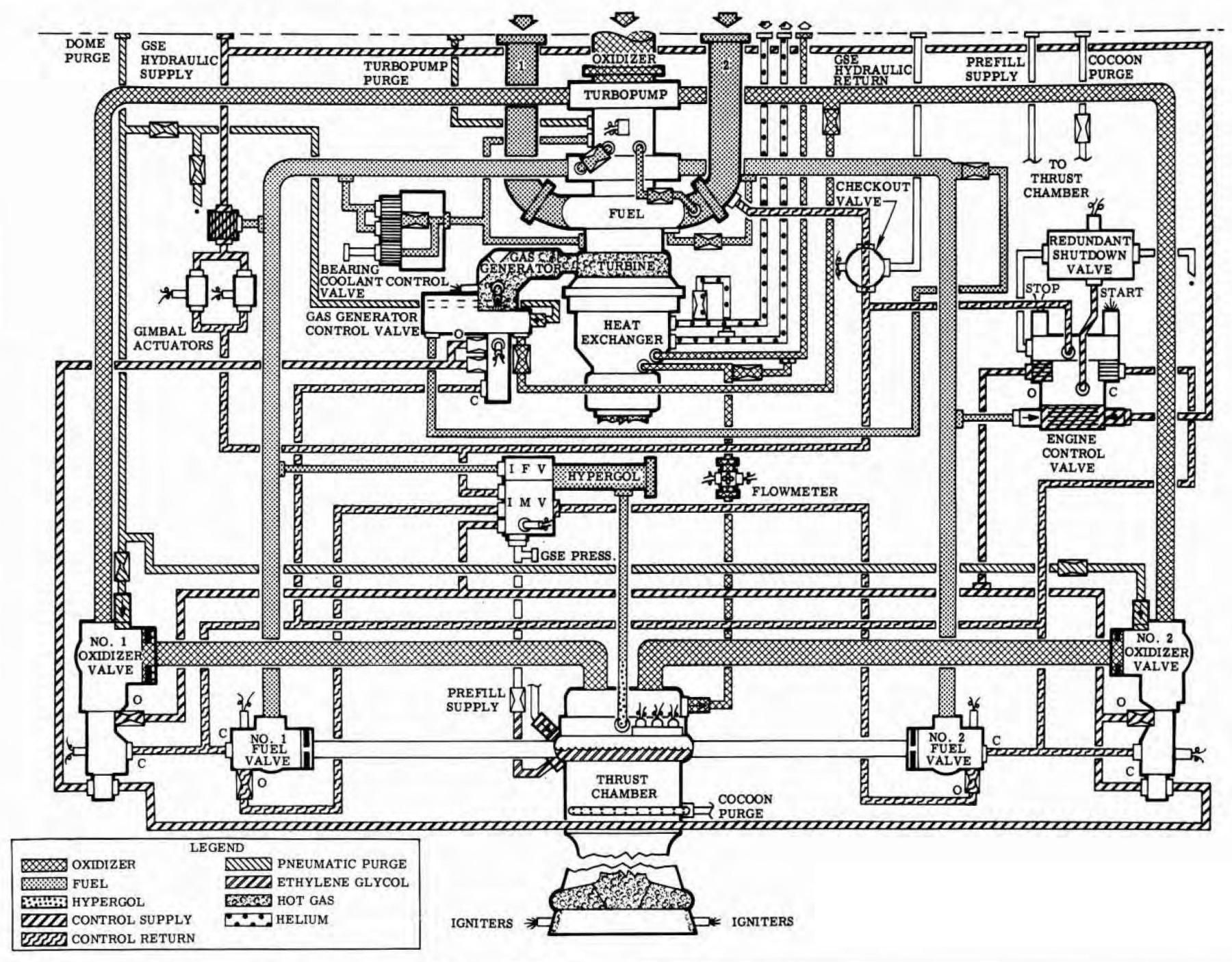
Engine Mainstage
Engine mainstage was that period of engine operation that was initiated when the engine reached 90% of its rated thrust. Thrust OK pressure switch actuation signaled mainstage. During the transition into mainstage, the control system pressure source was automatically transferred to the engine at the time engine fuel discharge pressure exceeded ground-supplied pressure. When the fuel valves reached the open position, the supply valve in the ground source control system supply line was closed. The ignition stage timer, which would have initiated an engine cutoff if the fuel valves had not opened within the time limit of the timer, expired and deenergized the engine control valve start solenoid. The control spool was unaffected, because the spool has been hydraulically locked in the valve's open position.
 |
| F-1 Mainstage |
Engine Cutoff
 |
 |
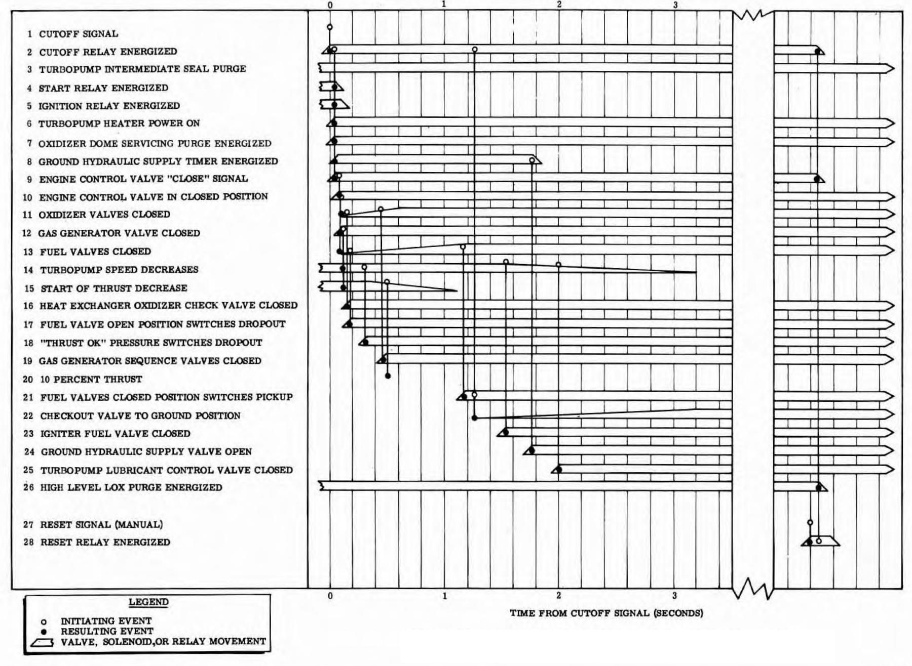 |
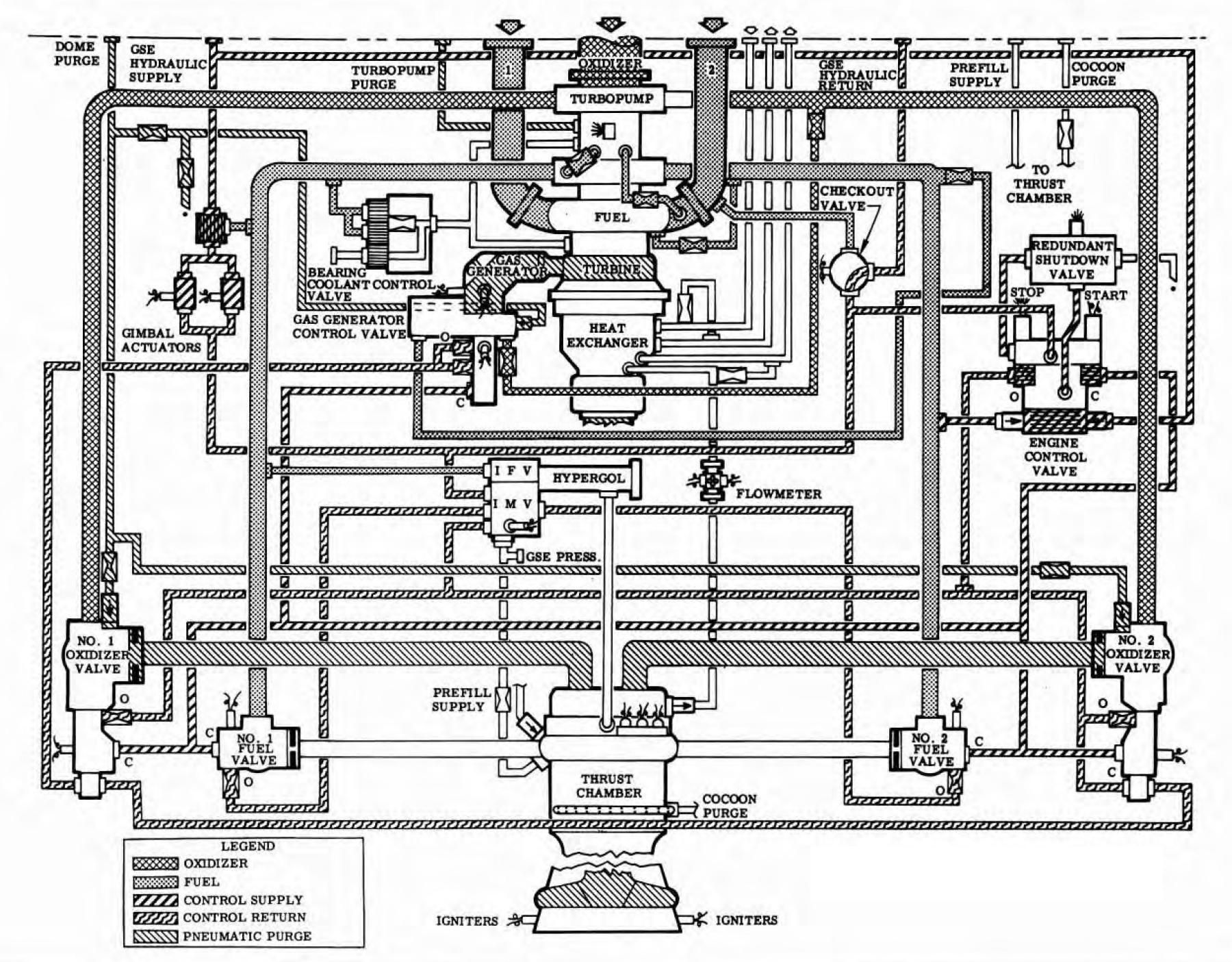
| Pictorial | Functional Flow | Timing |
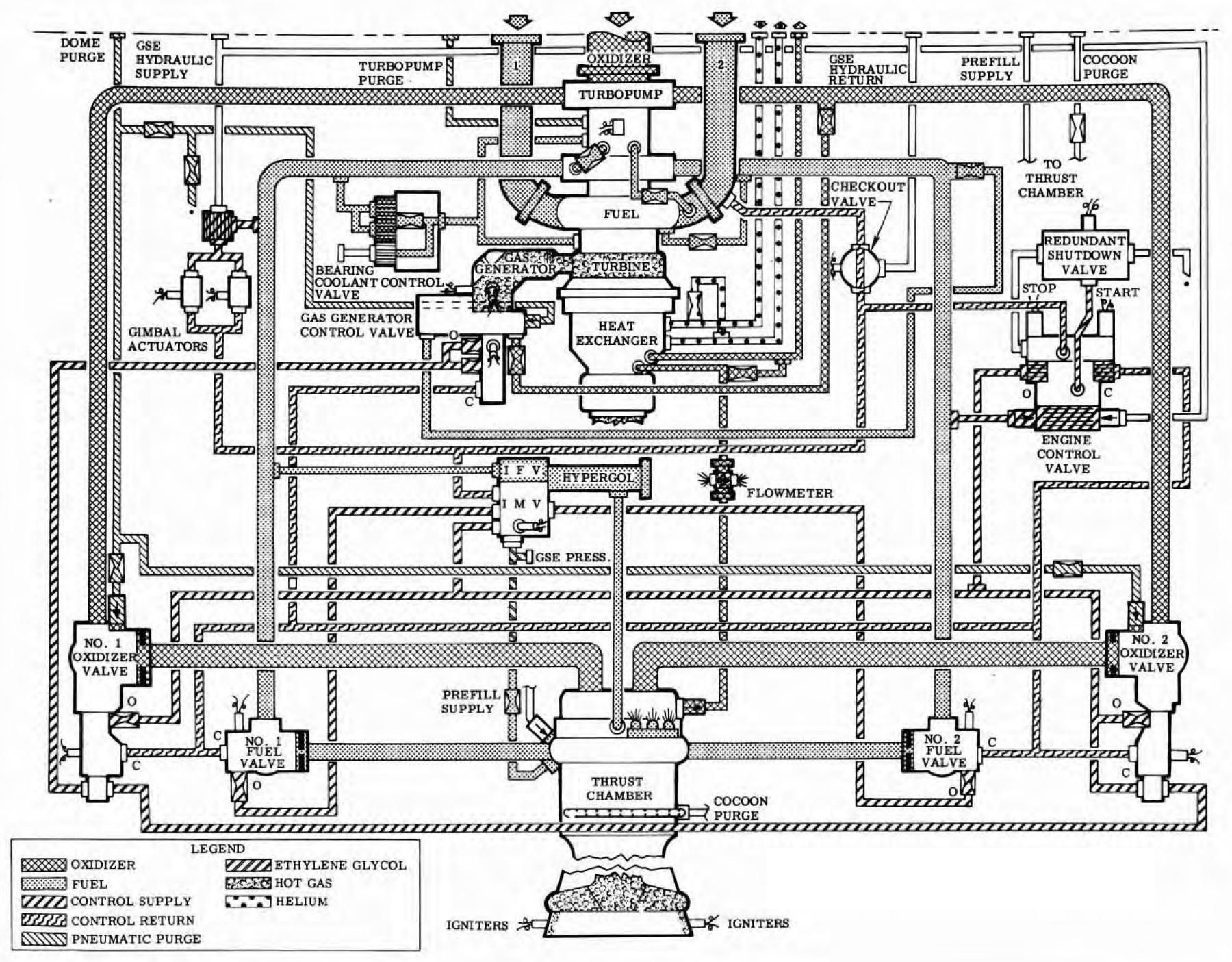
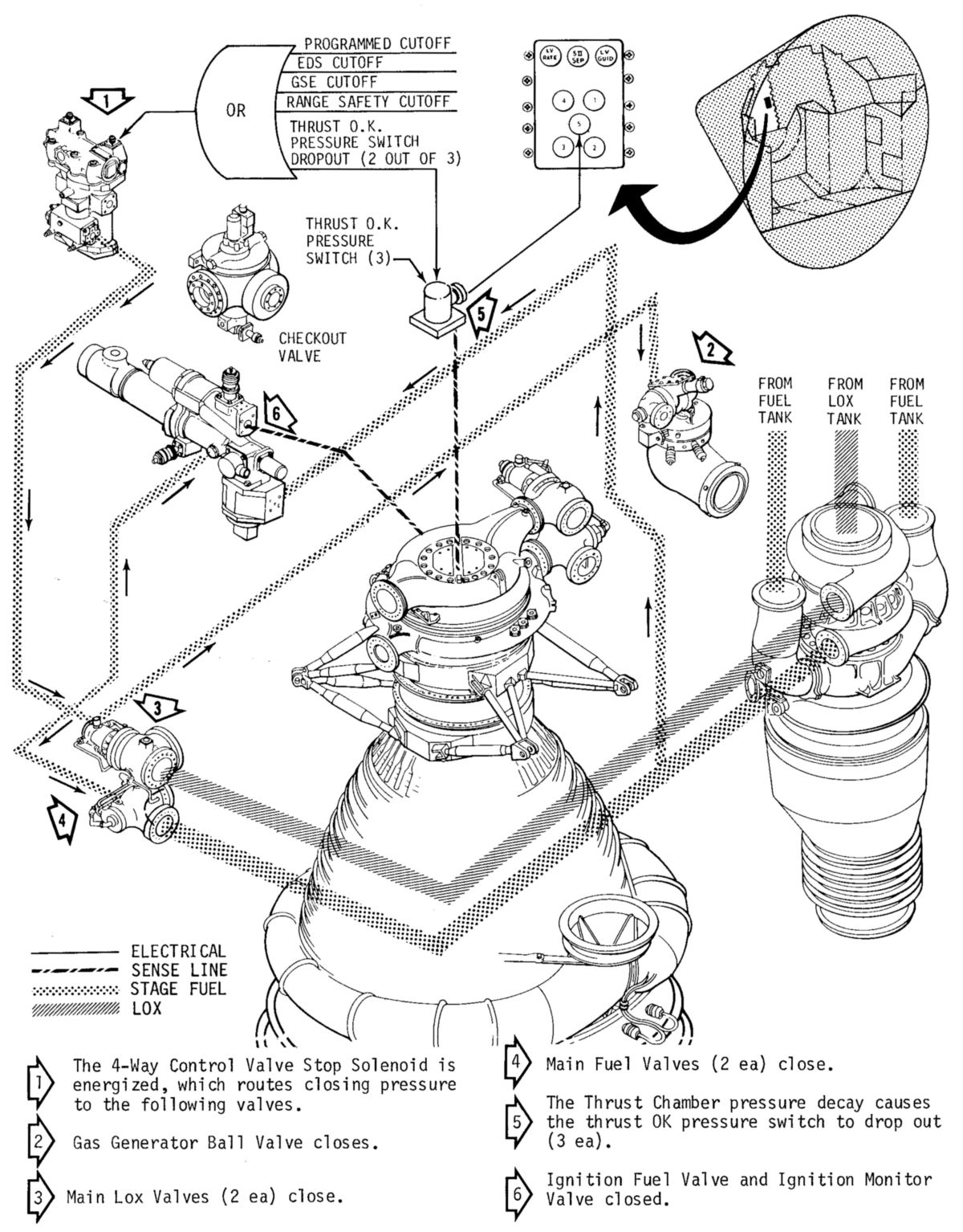
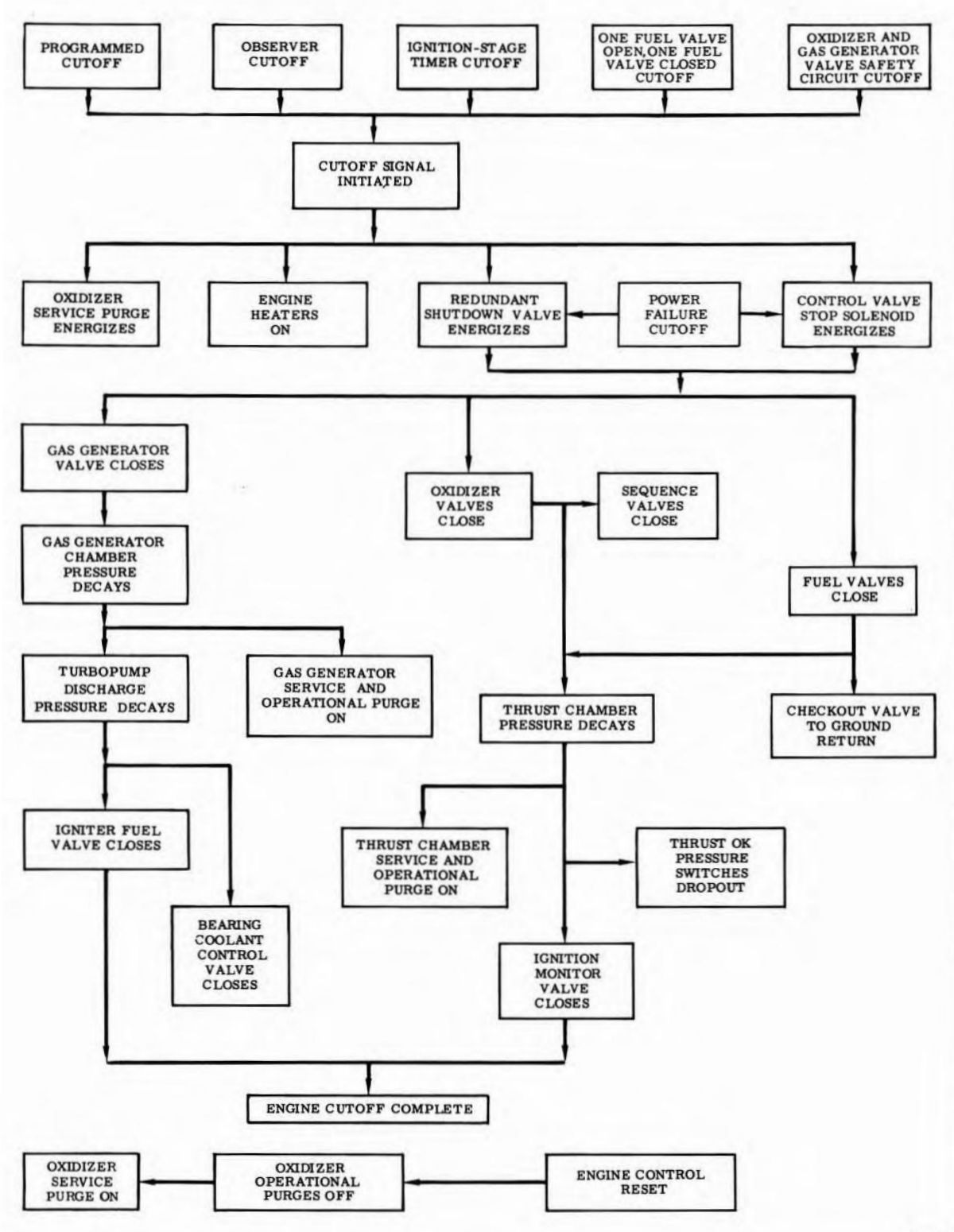
Engine cutoff was initiated electrically by simultaneously energizing the engine control valve stop solenoid and the redundant shutdown valve solenoid. When the engine control valve stop solenoid was energized, the control spool was shuttled to the valve's closed position; this removed opening pressure and applied closing pressure to the propellant valves. Energizing the redundant shutdown valve permitted the valve to hydraulically actuate and direct control system pressure to the engine control valve override port. Pressure to the override port caused the control spool to shuttle to the valve's closed position if the spool had not repositioned when the stop solenoid was energized. When closing control pressure was applied to the propellant valves, orifices in the control lines sequenced the gas generator control valve, oxidizer valves, and fuel valves closed, in that order.
When engine cutoff was initiated, the turbopump bearing heaters were reactivated and the oxidizer service purge was energized. Closing of the gas generator control valve removed power that drove the turbine and caused rapid decay of fuel discharge pressure. As fuel pressure decayed, the igniter fuel valve and bearing coolant control valves closed. Oxidizer and fuel valve closure caused thrust chamber combustion zone pressure to decay, which deactivated the ignition monitor valve.
 |
| F-1 Cutoff |
Post Cutoff Activities
When both the No. 1 and No. 2 fuel valves reached the closed position, the checkout valve was automatically returned to the ground return position and the ground source control system supply valve was reopened to supply closing pressure to the propellant valves until all residual propellants were drained from the engine. An inspection was performed, loose equipment was installed, modifications were made, and maintenance tasks were performed. Stage and engine leak and functional tests were performed, and final installation of the TIS was completed.
Send mail to
![]() with questions or comments about this web site.
with questions or comments about this web site.
![]()