A Brief History of Aircraft Carburetors and Fuel Systems
by Terry Welshans
Bardstown, Kentucky
for the Aircraft Engine Historical Society
August 2013
 |
The AEHS is pleased to present Terry Welshans' groundbreaking account of aircraft carburetor and fuel system history.
Terry Welshans grew up in Burbank, California, in the shadow of Lockheed Aircraft's plant B-1, Lockheed's original factory and home of the P-38. Terry began working as a "swamper" on a Bell 47G3B helicopter after graduating high school. The helicopter was leased to a US Forestry fire fighting crew that operated all over southern California.
From there, he worked in the tool room at Weber Aircraft, a manufacturer of ejection seats for Boeing B-52s, Cessna T-37s, and General Dynamics
F-106s. Weber also built seats for Gemini and Apollo spacecraft, along with tons of commercial airline seats, overhead storage, galleys and lavatories.
Terry was the 1967 Honor Graduate of the US Army's Fuel and Electrical Systems School. He received his private pilot certificate in 1968, and his commercial pilot certificate in 1974. Terry worked at Aircraft Carburetor in Burbank, where he overhauled almost every model of Bendix Stromberg and Marvel aircraft carburetors. Terry worked on a number of ADI regulators and carburetors for National Air Race competitors flying Vought F4U Corsairs, North American T-28s and P-51s, and Grumman F8Fs and F7Fs. The largest carburetor he worked on was a Bendix Stromberg PR100B4 for a Pratt & Whitney R-4360 engine used on a Boeing 377 being modified as the "Pregnant Guppy."
Terry attended classes at night, fitting them in between work and a growing family. He graduated in 1985, with a degree in workplace psychology. After retiring in 2006, Terry and his wife Carolyn moved to Bardstown, Kentucky. Terry and Carolyn recently purchased a Cessna 172, and plan on taking many trips across the United States.
|
Table of Contents
Table of Contents
Preface
Glossary
Bibliography
Introduction to Carburetion
– Aircraft Applications
– Fuel–Air Ratio Versus Engine Power
– Evaporative Carburetors
– Proportioning Carburetors
Aviation Fuels
– Fuel Chemistry
– The Engine
Float-Type Carburetors
– Backfire
– Preignition and Detonation
– Carburetor Ice
Modern Float-Type Carburetors
– Bendix Stromberg
– Marvel-Schebler
– Skinners Union (S.U.)
Ideas, People and Companies
– Carburetor Patents: 1920 and Beyond
– Carburetor Inventors
– Chandler Evans Company History
Floatless Carburetors — Chandler Groves, Holley and Chandler Evans
– Chandler Groves
– Holley
– Chandler Evans Hydro-Metering Carburetors
Floatless Carburetors — Bendix-Stromberg Pressure Carburetors
Speed-Density Systems
– Rolls-Royce/Skinners Union
– Bendix Stromberg
Fuel Injection
– Manifold Injection
– Direct Injection
Priming Systems
Anti-Detonation Injection
Summary
Preface
This work is a brief history of aircraft carburetors and fuel systems, beginning with a study of carburetor theory and design, as it existed in 1917. It was a time when inventors filed carburetor patents for every conceivable combination of designs, some of which were tested and others were not. Aircraft engines were also undergoing great changes in design, as were the aircraft themselves. To meet the changing needs peculiar to aviation, fuels, fuel systems, air induction systems and carburetors, a U. S. Government agency formed to test and evaluate aircraft, engines and all other components, eventually testing and evaluating all aspects of aviation. Originally named National Advisory Committee for Aeronautics (NACA), in 1958 it became the National Aeronautics and Space Administration (NASA), the agency that oversees aircraft and aerospace vehicles to this day.
Great use of the early NACA reports along with several books published prior to 1930 provided a basis from which the study of aircraft carburetors and fuel systems could begin. It is obvious by reviewing those reports that the understanding of engines, fuels, altitude and temperature was in the early stage of development. Much work was ahead in setting standards to insure safe designs and operational procedures.
A carburetor (American and Canadian spelling), carburator, carburettor, or carburetter (Commonwealth spelling) is a device that blends air and fuel for an internal combustion engine. It is sometimes, but not always, shortened to carb in North America and the United Kingdom. The word carburetor comes from the French carbure meaning "carbide"; Carburer is to combine with carbon. In fuel chemistry, the term has the more specific meaning of increasing the carbon (and therefore energy) content of a fluid by mixing it within a volatile hydrocarbon. Development continues for fuels built from these hydrocarbons, and will continue to do so until the discovery of a suitable alternative fuel.
In the opening days of the internal combustion engine, it was also necessary to design a carburetor for the engine, as none existed. Early attempts to supply fuel to a gasoline engine included a drip feed of fuel into the air intake pipe, or cotton wicks immersed in a pool of fuel with their tops exposed the airflow in the intake pipe.[1]
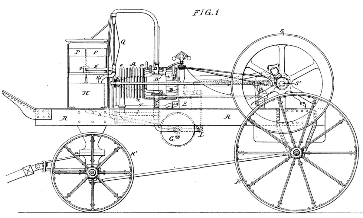
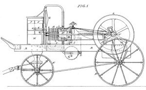
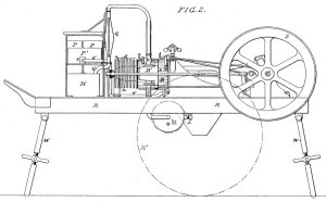
These inefficient methods of controlling the fuel mixture ended with the invention of a basic carburetor in 1863, attributed to Jean Joseph Étienne Lenoir (12 January 1822 – 4 August 1900. In 1863, Lenoir demonstrated a three-wheeled carriage, little more than a wagon body set atop a tricycle platform. Powered by a 2,543cc (155 in³; 180 mm x 100 mm, 7.1" x 3.9") 1.5 hp "liquid hydrocarbon" (petroleum) engine with a primitive carburettor, patented in 1886.[2] The patent for Lenoir’s carburetor description states:
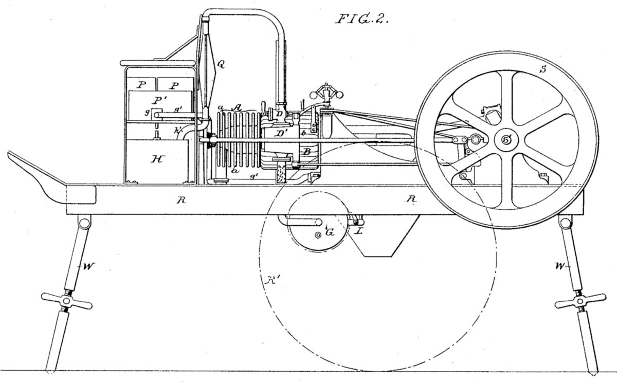
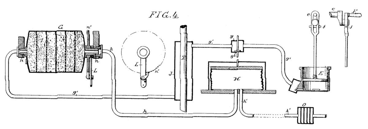
‘This carburetor consists of a cylinder provided at opposite ends with hollow journals, adapted to suitable bearings. The interior of the cylinder is provided with a series of perforated diaphragms and intermediate layers of sponge or similar absorbent material, and contains a hydrocarbon liquid. On one ratchet-wheel, n, with which engages a pawl on an arm, L, Figures 1 and 2. To this a vibrating motion is imparted from some moving part of the engine to impart a slow rotary motion to the cylinder to keep the sponge uniformly saturated with the hydrocarbon liquid, so that the air will also be uniformly saturated as it passes through the cylinder from the pipe J to the exit-pipe h and reservoir H. From thence the carbureted air passes through the tubes h to the gas-bag Q, Figs. 1 and 2, and thence to the gas-valve D, above the valve-chest D.’[3]
Lenior's carburetor, in other words, was a rotating hollow cylinder containing layers of an absorbent material. Air flowing to the engine absorbed this fuel as it passed through the cylinder. As the cylinder rotated, the absorbent material picked up more fuel from the fuel supply.
Lenoir's 1886 U.S. Gas Engine Patent No. 335,462
 |
 |
 |
| Fig. 1. Vehicle |
Fig. 2. Engine |
Fig. 4. Carburetor |
In 1876, Luigi De Cristoforis made the first carburetor in Italy. Enrico Bernardi at the University of Padua developed a carburetor for his "Motrice Pia," his first "petrol combustion engine." His one cylinder, 1,225 cc engine was prototyped on 5 August 1882.
In 1885, German inventors Wilhelm Maybach and Gottlieb Daimler developed a float type carburetor for their engine, based on the atomizer nozzle. A carburetor design was among Karl Benz's early patents as he developed his internal combustion engines and components.[4]
The Hungarian engineers János Csonka and Donát Bánki invented the world’s first carburetor for a stationary engine in 1893. At about the same time, the Austrian automobile pioneer Siegfried Marcus invented the rotating brush type carburetor.
By 1894, the German engineer Wilhelm Maybach developed a carburetor with the now familiar float-and-needle-valve arrangement. The float type carburetor maintains a reliable supply of fuel at a constant height. Karl Benz's "Patentwagen" of 1897 was equipped with one of Maybach's float-equipped carburetors.[5]
Some early carburetors were the evaporator type in which the air absorbs fuel as it passes over, bubbles up through the surface of gasoline or drawn through gauze that wicks the fuel up from its container.
Frederick William Lanchester of Birmingham, England, experimented with the wick type carburetor for cars. In 1896, Frederick and his brother built the first gasoline driven car in England, a single cylinder 5 hp (3.7 kW) internal combustion engine with chain drive. Unhappy with the performance and power they
re-built the engine into a two cylinder horizontally opposed version with his new wick type carburetor design.
Other early types of jet carburetors had a fuel supply to the engine that was more or less controlled by the size or number of the jet orifices. This type of carburetor was fitted either with a choke tube, of one constant diameter located round the jet orifice, or with a cone shaped tube, the position of which could be varied with regard to the jet.
The Longuemare carburetor of 1901 was first one of this type. In this design, a hand-controlled device admitted supplementary air. The arrangement was crude, as it was only capable of giving a correct mixture automatically for the one speed for which the choke tube was suited. As the speed increased so did the suction. The admission of air from an external source balanced the suction. In these early devices, extra air valves working against springs reduced the amount of hand manipulation necessary with such a device.
The early Krebs carburetor combined the extra air valve with the carburetor by means of air pressure actuating a diaphragm against the resistance of a spring, and in such an arrangement, it is possible to design the ports so that constant pressure difference with regard to the external atmosphere surrounds the jet.
The Kingston carburetor admitted the extra air needed as the load demanded it through a number of chambers, each with a ball and seat. Suction from the airflow lifts the balls from their seats in sequence, until the lifted balls provide extra air through the valve seats as needed. George Kingston invented this carburetor in 1902, and was standard on the Ford Model T automobile. Several large agricultural tractors used a larger version.
A further development of this principle, as claimed in the Gillet-Lehmann carburetor, a small pipe made a direct connection between the float chamber and the induction pipe at one or more points. Assuming that the restricting screw or screws were set properly, with a device of this nature it was possible to regulate the pressure difference under which the instrument worked with some degree of finesse. Devices of this nature were the forerunners of modern constant vacuum carburetors.
Another line of development aimed at restricting the flow of the liquid fuel as the engine suction increased. Such devices took the form of spirals of metal in the jet orifice. Obviously, arrangements of this sort could not give any great accuracy, and it was very difficult to obtain uniform carburetion at all speeds.
These devices were undoubtedly the forerunners of some of the later carburetors, in which the main feature was the variation of jet orifice in accordance with the demands of the engine. In several designs, the orifice consisted of at least two parts, which rotate relatively to each other, and in which the holes or orifices are circular, segmental, triangular or any other suitable shape, and which give an orifice opening in proportion to the air and throttle opening.
Carburetors of this type possessed a great degree of accuracy, and required very little final adjustment. There were further carburetor developments where additional air devices, some with either pneumatically or hydraulically controls, gave excellent results. In such a combination, however, more than one type of adjustment was required, and the carburetor immediately became liable to derangement and erratic working when in the hands of an inexperienced user.
Furthermore, the air-controlling arrangement was liable to suffer as the operating mechanism wears, the spring control loses its original liveliness or the moving parts stick or become loose.
Carburetors were the usual method of fuel delivery for most gasoline-fueled automobile engines until the late 1980s, when fuel injection became the preferred method of delivering fuel. Fuel injection systems that include an electronic integrated engine control systems such as the ‘full authority digital engine control’ (FADEC) systems are beyond the scope of this article, and will be the subject of future articles.
A discussion about aircraft carburetors is not complete unless a discussion of engines and fuels are included, as the development and improvement of any one of the three calls for experimentation, development and testing of the others, as all three must work together as a single power system.
Endnotes
[1] Bosch Fuel Injection Systems.
[2] The World of Automobiles, p 1181.
[3] US patent 345,596.
[4] Bosch Fuel Injection Systems, Ch 1.
[5] Bosch Fuel Injection Systems, Ch 1.
Glossary
Air: Air is a breathable, non-toxic mixture of four parts nitrogen and one part oxygen, with an umber of other gasses in very small quantities. In combustion, the oxygen unites with the hydrogen and carbon parts in the hydrocarbon fuel, producing a hot gas made from the reconstituted hydrocarbon, nitrogen and oxygen atoms combined in new configurations. Air expands when heated, and when it is contained, its pressure increases. Under high-heat combustion, nitrogen in the air combines with surplus oxygen to form oxides of nitrogen (NOX), a component of photo-reactive smog.
Air-Fuel Ratio: See Fuel–air ratio.
Atom: In chemistry, an atom is a basic unit of matter that consists of a dense central nucleus surrounded by a cloud of negatively charged electrons. The outermost electron shell of an atom in its uncombined state known as the valence shell. The electrons in that shell are called valence electrons. The number of valence electrons determines the bonding behavior with other atoms. Atoms tend to chemically react with each other in a manner that fills (or empties) their outer valence shells. Hydrocarbon molecules form when hydrogen and carbon atoms join.
Atomize: Reducing a liquid into very small droplets to assist in its evaporation.
Autoignition: The spontaneous ignition that results when the heated fuel–air mixture reaches the point where it ignites with no external ignition source. Diesel engines use the principle of autoignition. In a diesel engine, fuel injected into the highly compressed high-temperature air within the engine cylinder ignites as it mixes with the heated air.
Aviation Fuel: A mixture of various hydrocarbons that has specific combustion characteristics. Aviation fuel must meet pressure and temperatures found at high altitude as well as at the earth’s surface. A basic aviation fuel usually has three primary hydrocarbons and an untold number of other hydrocarbons or other chemicals.
BMEP: ( Brake Mean Effective Pressure) - The mean effective pressure calculated from brake power, abbreviated as MEP.The mean effective pressure is a quantity relating to the operation of a reciprocating engine and is a valuable measure of an engine's capacity to do work that is independent of engine displacement. A torque meter instrument indicates BMEP engine output.
Combustion: The common name for the reduction and reaction within a fuel–air mixture where the fuel and air are ignited and broken down to their atomic constituents and then reformed into the gases that flow through the exhaust system. Heat released in this reaction expands the gases created.
Carburetor: A carburetor (American and Canadian spelling), carburator, carburettor, or carburetter (Commonwealth spelling) is a device that blends air and fuel for an internal combustion engine. It is sometimes, but not always, shortened to carb in North America and the United Kingdom. The word carburetor comes from the French carbure meaning "carbide".[1] Carburer means to combine with carbon. In fuel chemistry, the term has the more specific meaning of increasing the carbon (and therefore energy) content of a fluid by mixing it with a volatile hydrocarbon.
Detonation: The uncontrolled autoignition of the fuel–air mixture after the normal ignition has occurred. The combustion pressure and radiated infrared energy building within the cylinder compresses the unburned mixture, bringing it to the temperature where it spontaneously ignites. The ignition results in a dramatic pressure increase within the cylinder, creating a number of high velocity pressure waves. The resulting temperature may be high enough to burn or melt pistons and damage valves.
Engine: A device engineered to accept a combustible mixture, compress it, ignite it, and use the increased gas volume caused by the temperature increase to provide thrust, which moves the aircraft.
Evaporate: As heat is absorbed into a liquid, the liquid temperature will rise to its vapor pressure threshold, where liquid fuel is gasified into a vapor. This change of state from a liquid to a gas removes heat from the remaining liquid, cooling it. This process is similar to refrigeration, in that it cools water vapor within the airflow to its saturation point, causing the water vapor to condense into a liquid, freezing any moisture within the vapor if cooled below the freezing point.
Evaporative Carburetor: A type of carburetor that incorporates fuel vapors into the air flowing through it by passing the air across the fuel surface, through a wick that is suspended in the fuel, or by bubbling the air through the fuel. This is a non-proportioning carburetor and is best for use on an engine that operates at a steady load and speed, as it cannot provide a correct fuel–air ratio except for that one operating condition.
Float-Type Carburetor: A type of carburetor that reduces fuel pressure to atmospheric pressure by a valve that is operated by a float. This type of carburetor is sensitive to the forces of gravity, acceleration, and aircraft attitude. A float-type carburetor works poorly or not at all when the aircraft is inverted, and under certain conditions is plagued by ice formation that chokes airflow, reducing engine performance.
Floatless Carburetor: This carburetor design eliminates the fuel-level set by a float in a typical carburetor by replacing it with a diaphragm-operated valve. The valve operates to reduce the fuel pressure to atmospheric pressure, which is modifiable to include altitude and temperature compensation.
Formula: A method of expressing the chemical reactions under a given condition. Formulas are the numeric representation of molecules, with the number of elemental atoms shown as a subscript number following the element name. For example, water results when two hydrogen atoms combine with one oxygen atom. The formula for water is H2O.
Fuel: An internal combustion engine burns a mixture of fuel and air to produce useful work. The amount of heat released by a given fuel, mixed at the correct fuel–air ratio, varies with the molecular construction of the hydrogen, carbon, and other elements within the molecule. In a piston engine, fuels that contain high hydrogen levels are the most energetic, and those molecules with complex internal structures burn slowly, preventing detonation at high compression
ratios.
Fuel–Air Ratio: The number of parts of fuel (in pounds) compared to parts of air (in pounds). For example, a 1:8 fuel to air ratio is one pound of fuel mixed with eight pounds of air. Fuel–air ratio is equivalent to air-fuel ratio, worded in the reverse. For example, the 1:8 fuel to air ratio can also be expressed as being an 8:1 air to fuel ratio as eight pounds of air is mixed with one pound of fuel. In either case, about 12.5% of the mixture is fuel and the remainder is air.
Fuel Injection: A method of providing a precise amount of fuel under sufficient pressure, spraying the fuel either into the air flowing into an engine, or directly into the combustion chamber. Fuel injection delivers the same fuel charge to every cylinder, resulting in consistent temperature and pressure within all of the cylinders.
Hydrocarbon A number of hydrogen and carbon atoms combined into a molecule with a specific configuration that is limited to the arrangements permitted by the bonds between the atoms in the mix. A hydrocarbon can be a gas, liquid, semi-solid or solid, as determined by the number of carbon atoms in a single molecule. The fuel molecule can be in a number of configurations, those with the most complex configuration release more energy when ignited in a high compression engine. Hydrocarbons vary in arrangement, and are found as a simple endless "straight chains", more compact, complex branching chain arrangements that incorporate branches of additional carbon atoms (which allow additional hydrogen atoms to join in the arrangement), or in rings where the ends of the straight chain are joined to one another.
Jet: In reciprocating engine carburetors, a jet is a replaceable orifice that causes a precise pressure drop as a fluid flows through it. A jet is an accurately made precision part constructed to retain its flow characteristics. The internal diameter of the jet and the length of the reduced diameter combine to produce a given pressure drop as the fuel flows through the jet. This pressure drop through a jet is constant, and remains unchanged when the rate of flow through the jet changes.
Molecule: The smallest part of matter that retains the characteristics of the whole, and is further divisible only into individual atoms. Hydrocarbon molecules are the building blocks that combine for their specific characteristics to produce fuel with a given resistance to autoignition.
Nozzle: A part of the fuel system that sprays fuel into the air flowing into the engine. It may be inside the carburetor venturi, below the throttle plates, at the air inlet to the supercharger, at the intake valve, in the cylinder head or any other place determined to be suitable for its intended purpose.
Preignition: The autoignition of the fuel–air mixture within the engine cylinder before normal ignition occurs. The ignition results when the fuel–air mixture temperature reaches the autoignition point as it is compressed. Preignition results from very high inlet air temperatures or high compression ratios.
Pressure Carburetor: A carburetor design where the fuel within the carburetor is pressurized to a point where it is ejected from the discharge nozzle as a spray. A pressure carburetor typically has a regulator section that senses pressures at specific points within the airflow and fuel flow to constantly adjust the amount of fuel flowing to a prescribed amount, over the entire engine operating range.
Proportioning carburetor: This type of carburetor measures the air flowing through it, and adjusts the fuel flow accordingly, to provide the correct fuel–air ratio under all operating conditions.
Stochiometric Point: In the combustion reaction, oxygen reacts with the fuel, and the point where exactly all oxygen is consumed and all fuel burned is defined as the stoichiometric point. With more oxygen, some of it stays unreacted. Likewise, if the combustion is incomplete due to lack of sufficient oxygen, fuel remains unreacted. Different hydrocarbon fuels have a different contents of carbon, hydrogen and other elements, thus their stoichiometry varies.
Suction: The correct term for any relatively low-pressure area within an engine intake system. Air flows from high-pressure areas to low-pressure areas. In a normally aspirated engine, that is, one without a turbocharger or supercharger, air can leak into the system due to the suction created by the engine drawing air into the intake manifold, leaning the mixture. On engines with boost pressure greater than atmospheric, the fuel–air mixture will leak out, reducing engine power.
Supercharger: A mechanically driven air compressor. High-power aircraft engines typically have a centrifugal supercharger built into the crankcase. The supercharger impellers driven by a series of gears to a speed greater than the speed of the crankshaft, and may consume considerable power at full speed. Superchargers may have up to three gear ratios that provide optimum manifold pressure at various altitudes, and may have a turbocharger or a second supercharger to create a two-stage induction system.
Throttle: A valve that opens and closes to control the volume of air entering the engine induction system.The shape and number of parts varies by the design of the carburetor. The throttle plate is designed to precisely fit the shape of the air passage. A carburetor with a round air passage will have a single plate on a rotating shaft, while a carburetor with a rectangular air passage could have two or more flat or other shaped plates that operate in unison to control the airflow.
Turbo(super)charger: An exhaust gas turbine-driven centrifugal air compressor. A turbine wheel that is coupled to a compressor wheel absorbs energy from the expansion of exhaust gases after combustion. The compressor provides compressed air to the engine supercharger. A turbocharger restricts the engine exhaust, thereby raising the pressure in the exhaust manifold, reducing the exhaust to intake pressure ratio, and slightly reducing engine horsepower. Advantages of using a turbocharger far outweighs its disadvantages.
Vacuum: Used in the context of this article, vacuum refers to a pressure that is lower than atmospheric. One vacuum may have less pressure than another vacuum. The term suction is more correct, as a true vacuum is the result of the complete evacuation of all gas, a condition that does not exist within an engine or carburetor. In an engine, suction is created in the intake manifold as the piston is moved toward the crankshaft. The intake manifold suction is controlled by the position of the throttle. When a supercharger is installed, intake manifold suction may be eliminated and a positive manifold pressure developed as more air is admitted to the intake manifold than is drawn in by the piston movement.
Venturi: A restriction within a tube where fluid flow velocity is increased and the pressure is reduced at its narrowest place, as described by Bernoulli. The shape of a round venturi is similar to two smoothed, truncated cones that join their smaller ends at the venturi’s narrowest point. In a rectangular venturi, only two sides will have the tapered shape, the others remaining flat. To avoid undue drag, a venturi typically has an entry cone of 30° and an exit cone of 5°. According to the laws governing fluid dynamics, a fluid's velocity must increase as it passes through a constriction to satisfy the principle of continuity, while its pressure must decrease to satisfy the principle of conservation of mechanical energy. Thus, a drop in pressure negates any gain in kinetic energy that a fluid may accrue due to its increased velocity through a constriction. An equation for the drop in pressure due to the venturi effect derives from a combination of Bernoulli's equation and the continuity equation. The low pressure created within a venturi is determined by the velocity and density of the fluid flowing through it. The venturi effect is a jet effect; the velocity of the fluid increases as the cross sectional area decreases, with the static pressure correspondingly decreasing. The venturi is named for Giovanni Battista Venturi, an Italian physicist. Bernoulli's equation is named for Swiss scientist Daniel Bernoulli, who published his principle in the 1738 book, Hydrodynamica.
Bibliography
Aird, Forbes. Bosch Fuel Injection Systems. HP Books, 2001.
Baukal Jr., Charles E., editor. The John Zink Combustion Handbook. John Zink Company, 2012.
Cessna 152 Information Manual. Cessna Aircraft Company, 1 July 1979.
Dickey III, Philip S. “The Liberty Engine 1918-1942.” Smithsonian Annals of Flight Volume 1 Number 3. Smithsonian Institution Press, National Air and Space Museum, Washington, D.C. 1968.
Dyke, A. L. "Zenith Carburetors." Dyke's Automobile and Gasoline Engine Encyclopedia, 12th edition,. 1922.
Engine Conditioning For Reciprocating Engines. Department of the Air Force Manual 52-9. Washington, March 1953.
Fernandez, Ronald. Excess Profits: The Rise of United Technologies. Boston, Massachusetts, Addison-Wesley, 1983.
Flight Manual USAF Series A-26A Aircraft (On Mark). Department of the Air Force Technical Order TO 1A-26A-1 (Formerly TO 1B-26K-1). Washington, 1 September 1969
Heron S. D. Development of Aviation Fuels. Harvard University, 1950.
Holley Aircraft Carburetors Instruction Manual, Third Edition. Holley Carburetor Company, January 1941.
Manual of Stromberg Aircraft Carburetors, Edition II. Stromberg Motor Devices Co., 1927.
NACA Technical Report No. 11. Carburetor Design: a Preliminary Study of the State of the Art. Lucke, Charles Edward and Willhofft,
Friederich Otto. 1917.
NACA Technical Report No. 48. Carbureting Conditions Characteristics of Aircraft Engines. Tice, Percival S. 1920.
NACA Technical Report No. 49. Discharge Characteristics of Fuel Metering Nozzles in Carburetors. Tice, Percival S. 1920.
NACA Technical Report No. 102. Performance of a Liberty 12 Engine. Sparrow S.W. and White, H.S. 1920.
NACA Technical Report No. 189. Relation of Fuel–air Ratio to Engine Performance. Sparrow, Stanwood W. 1925.
NACA Report No. 250. The NACA Universal Test Engine and Some Test Results. Ware, Marsden. 1938.
NACA Technical Note No. 647. Engine Performance and Knock Rating of Fuels for High-Output Aircraft Engines. Rothbrock, A.M. and Biermann, Arnold E. April 1938.
NACA Technical Memorandum No. 853. Effect of Air-Fuel Ratio on Detonation in Gasoline Engines. Peletier, L.A.1938.
NACA Technical Report No. 655. The Knocking Characteristics of Fuels in Relation to Maximum Permissible Performance of Aircraft Engines. Rothcock, A.M. and Biermann, Arnold E. 1939.
NACA Advance Restricted Report No. 3H13. Deicing of an Aircraft-engine Induction System. Essex, Henry A. National Bureau of Standards, August 1943.
NACA Memorandum Report No. L4L18. Flight Tests of the High Speed Performance of a P-51B Airplane (AAF43-12105). Vogelwede, T.J.and
Danforth, E.C.B. Dec 18, 1944.
NACA Memorandum Report No. E5D24. Effect of Fuel Volatility and Mixture Temperature on the Knocking Characteristics of a Liquid-cooled Single-Cylinder Test Engine. Tauschek, Max J. and Lietzke, A.F. April 1945.
NACA Advance Restricted Report No. E4J05, The Knock-Limited Performance of Fuel Blends Containing Aromatics Part I: Toluene, Ethyl Benzene and p-Xylene. Meyer, Carl L. and Branstetter, J. Robert. October 1944.
NACA Advance Restricted Report No. E5A20. The Knock-Limited Performance of Fuel Blends Containing Aromatics Part II: Isopropylbenzene, Benzene, and o-Xylene. Meyer, Carl L. and Branstetter, J. Robert. January 1945.
NACA Advance Restricted Report No. E5D16. The Knock-Limited Performance of Fuel Blends Containing Aromatics Part III: 1,3,5-trimethylbenzene, tert-butylbenzene and 1,2,4-trimmethylbenzene. Meyer, Carl L. and Branstetter, J. Robert. 6 April 1945.
NACA Advance Restricted Report No.E5D16a. The Knock-Limited Performance of Fuel Blends Containing Aromatics Part IV: Data for m-diemethylbenzene, 1-ethyl-4-methylbenzene and sec-butylbenzene. Together with a Summarization of Data for 12 Aromatic Hydrocarbons. Meyer, Carl L. and Branstetter, J. Robert. April 1945.
NACA Advance Restricted Report No. E6C05. The Knock-Limited Performance of Fuel Blends Containing Aromatics Part V; n-propelbenzene, n-butylbenzene, isobutylbenzene, m-xylene, and 1-isopropyl-4-methylbenzene. Meyer, Carl L. and Branstetter, J. Robert. 1946.
NACA Memorandum Report No. E6C25. Hydraulic Characteristics of the NACA Injection Impeller. Ritter, William K. , Johnsen, Irving A. and Lieblein, Seymour. May 1946.
Pollard, Harol. Aero Engines, Magnetos and Carburetors. The MacMillan Company, 1918.
Powerplant Handbook. US Department of Commerce Civil Aeronautics Administration Technical
Manual No.107. January 1949.
Powerplant Maintenance for Reciprocating Engines. Department of the Air Force Air Force Manual Number 52-12. Washington, May 1953.
Publication AN 03-108F-1. Handbook of Instructions with Parts Catalog: Hydro-Metering Carburetor Model 58-4. Commanding General, Army Air Forces, the Chief of the Bureau of Aeronautics, and the Air Council of the United Kingdom. 5 July 1944.
Publication AN 03-10C8-1. Operation, Service, and Overhaul Instructions with Parts Catalog for Gasoline Injection System Model 58-18-A2B. Commanding General, Army Air Forces, and the Chief of the Bureau of Aeronautics. 30 January 1946.
Publication AN 03-CA-1. Operation, Service, and Overhaul Instructions with Parts Catalog for Direct Fuel Injection System Models 58-18-A1A, 58-18-B1A and 58-18-C1A. Commanding General, Army Air Forces, and theChief of the Bureau of Aeronautics. 7 December 1945.
Schlaifer, Robert. Development of Aircraft Engines. Harvard University, 1950.
Sherbondy, E.H. and Wardrop, G. Douglas.Textbook of Aero Engines. Fredrick A. Stokes Company, 1920.
The Aircraft Engine and its Operation. United Aircraft Corporation, Pratt & Whitney Aircraft Division, 1952.
The Claudel-Hobson Carburettor Models R. A. F., Z & HC7, for Aero Engines: Instruction Manual. Technical Information Section, T.3.F., Air Board, 1918.
Thirty-fifth Annual Report. National Advisory Committee for Aeronautics, 1949.
Thorner, Robert H. Aircraft Carburetion. John Wiley & Sons, Inc., 1949.
Whitney, Daniel D. Vee’s For Victory. Schiffer Military History, 1998.
Wise, David Burgess. "Lenoir: The Motoring Pioneer." The World of Automobiles. Orbis Publishing, 1974.
Zhao, F., Lai, M., Harrington, D. l, Editors. “Automotive Spark-Ignited Direct-Injection Gasoline Engines.” International Journal Progress in Energy and Combustion Science, Volume 25:5. 1999.
Investigation Report 200002157 by Department of Transport and Regional Services Australian Transport Safety Bureau Re: Piper PA31-350 Chieftain VH-MZK at Spencer Gulf SA on 31 May 2000
CFR Title 14 Para 33.47. Detonation Test and EASA CS-E 360 Detonation Tests.
Dowling, Brian. The Hartford Courant.
IUPAC Compendium of Chemical Terminology Gold Book, International Union of Pure and Applied Chemistry Version 2. 3. 2. 2012.
Note 1: The NACA issued reports in a number of different series, some as part of their annual report, which are “Technical Reports”
and “Technical Notes”. Others were issued as Advance Restricted” Reports, “Memorandum Reports”, “Restricted Bulletins”, “Technical Memorandums” under the general category of “War Reports”. Many of the documents have the same number, resulting in confusion if consulting the wrong series of reports, as the report titles are different, yet have the same number.
Note 2: All NACA files used in this publication are downloadable at: University of North Texas UNT Digital Library