Used on Pratt & Whitney R-1340-AN1, -47, -49 and -51 Engines
A Brief History of Aircraft Carburetors and Fuel Systems
Part 5: Modern Float-Type Carburetors
by Terry Welshans
Bardstown, Kentucky
for the Aircraft Engine Historical Society
Published August 2013; Revised 3 Sepember 2022
Table of Contents
Great improvements in mixture control came about after 1920. This was due in part to advances made in engineering and chemistry and in the improvements in higher education. The gains made were in parallel with the aircraft and automotive requirements, which were performance driven by the publicity and popularity of racing. Recall that James Allison was motivated to get the maximum performance possible at the Indianapolis speedway, a hobby that eventually led to the development of the Allison aircraft engine. In 1904, Harry C. Stutz, who was involved in the design and manufacture of internal combustion engines, introduced George Schebler to Frank W. Wheeler. In the resulting partnership, Wheeler provided the money, while Schebler provided engineering skills. Stutz worked temporarily as Sales Manager. By 1907, they had achieved enough success to move to Indianapolis into a state-of-the-art building, a plant that reportedly was one of the most advanced manufacturing facilities in the United States at the time. Frank Wheeler and three other local men (including James Allison) opened the Indianapolis Motor Speedway in 1909. Prior to the inauguration of the Indianapolis 500 in 1911, the Wheeler-Schebler company sponsored the Wheeler-Schebler Trophy Race at the track. George Schebler sold his interests in the company in 1912, but it continued to operate under the Wheeler-Schebler name until 1928, when it evolved into the Marvel-Schebler Carburetor Company, one of five companies that played a role in the development of what that would become the Borg-Warner Corporation. The factory produced carburetors from 1911 up to 1951. Indianapolis 500 winners receives the Borg-Warner Trophy to this day.
Bendix Stromberg Float-Type Carburetors
Bendix Stromberg Carburetor Identification Scheme
Bendix Stromberg used a unique identification scheme where a series of letters and numbers were assembled to identify and describe how a carburetor was constructed. The first two letters described the carburetor design, followed by a number that identified the size, and numbers and letters to identify specific design details and modifications.
Example: NA-R9G
Prefix- "NA" – for float-type carburetors followed by a "-"(dash)
Bendix Stromberg NA-S2 and NA-S3 Carburetors
The Stromberg NA-S2 and NA-S3 carburetors meet the requirements of small two, three and four cylinder aircraft engines used in small airplanes. The principles of operation are quite similar to those used in all Stromberg aircraft and motorcar carburetors. The specification or setting in the carburetor is the result of a great deal of test work conducted by the engine and carburetor manufacturers in the laboratory and in flight, and should not be changed unless it is absolutely certain that a change is necessary to meet unusual operating conditions.
Description and Function
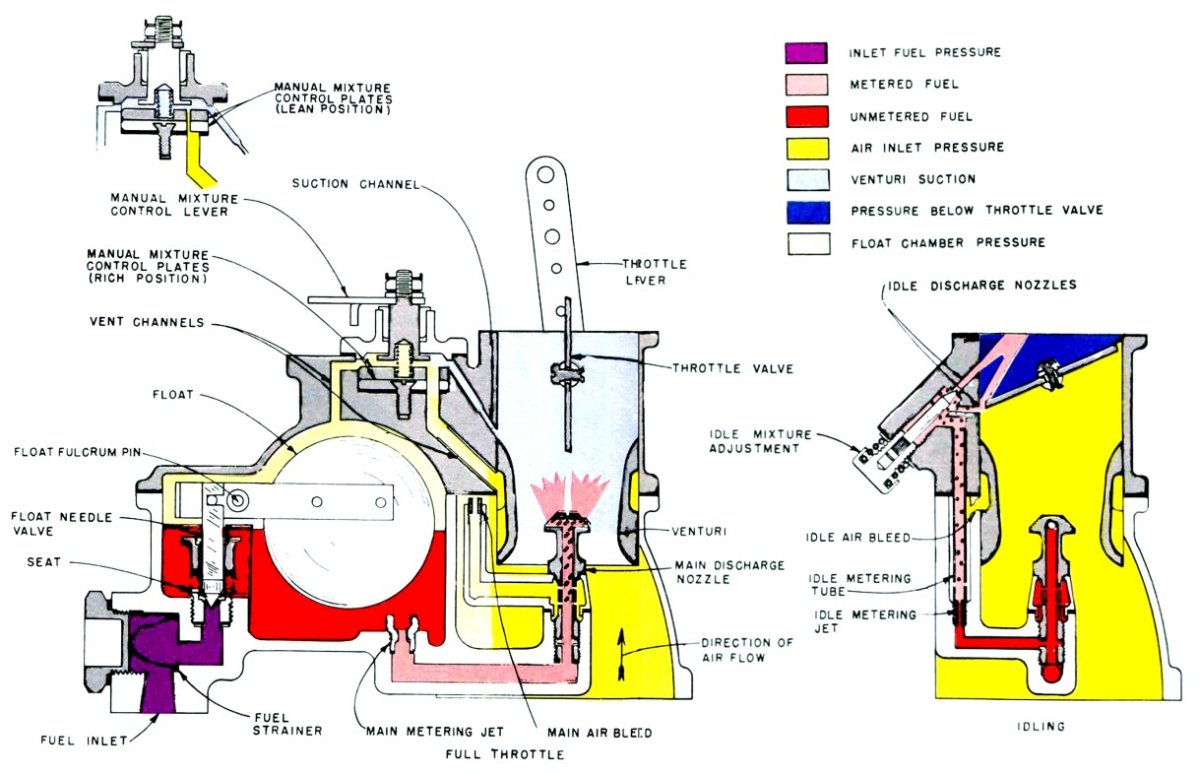
Float Mechanism. – A conventional hinge type of float mechanism located in a float chamber having ample fuel capacity to operate in all ordinary maneuvers is used. The factory adjusts the float mechanism to obtain the proper fuel level, and requires no adjustment in service unless it is necessary after a long period of service to install new parts.
Main Metering System – The metering system is of the plain tube type with an air bleed to the main discharge nozzle. The main discharge nozzle screws into a boss projecting into the air intake at the center of the venturi. The main air bleeder screws into the air bleed arm held in place by the main discharge nozzle. The main metering jet is in the bottom of the float chamber in a channel through which the fuel flows to the main discharge nozzle. The actual metering of the fuel takes place at the discharge nozzle openings. The size of the main metering jet affects the fuel consumption at all speeds from approximately 1,000 rpm to full throttle speed.
Idling (Slow Running) System – As the main metering system will not function at very low airflows (low engine speed), an idling system is provided. This consists of an idle tube with an idle metering orifice in the bottom and several air bleed holes in the wall, an idle air bleed, and two holes in the throttle barrel, which act as idle discharge nozzles. A needle valve type of adjustment on the upper discharge nozzle regulates the quality of the idle mixture. Fuel for the idle system comes from the annular space around the main discharge nozzle, passes through the idle metering jet and mixes with the air from the idle air bleed located in the main body behind the venturi. The air enters the tube through the bleed holes and the mixture then passes out of the upper or lower idle discharge hole. The relative quantities passing through the upper and lower idle hole depends upon the position of the throttle. At extreme idle, all the fuel passes through the upper hole and as the throttle opening increases, more and more of it passes through the lower hole. The idle system operates up to an engine speed of approximately 900 to 1000 rpm.
Bendix Stromberg has produced float-type aircraft carburetors in a number of sizes, ranging from the 1-1/8" venturi NAS-2 to the 3-1/8" venturi NA-12 series.
|
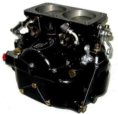
|
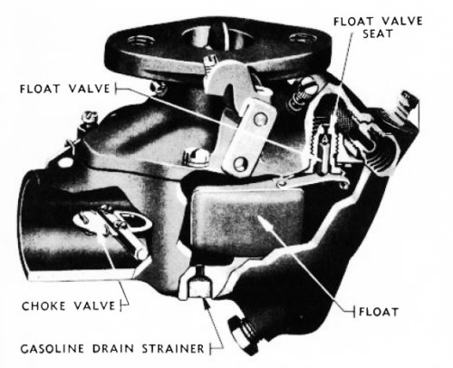
| Fig. 43. Bendix NAY-9E1 Float-Type Carburetor Used on Pratt & Whitney R-1340-AN1, -47, -49 and -51 Engines |
Fig. 44. Bendix Stromberg NA-S3A1 Carburetor Schematic |
Originally known as the Wheeler-Schebler carburetor company, it became Marvel-Schebler Carburetor Company when it merged with Marvel Carburetor Company. The Marvel-Schebler company did some early work connected with developing fuel-injection systems in the late 1950s and early 60s, eventually merging with the Borg Warner owned Tillotson Carburetor Company in 1971. In 1985, parent company Borg Warner changed the division name to "Control Systems." Borg-Warner went through a leveraged buyout in 1987, spinning off the Borg Warner Automotive Inc., as an independent company that is still in operation, developing fuel-efficient engine and drive train technology. Marvel-Schebler/Tillotson spun away from Borg-Warner to become Facet Aerospace Products Company, which first became Precision Airmotive Corporation, then Volare Carburetors LLC, then Marvel-Schebler® Aircraft Carburetors (MSA). MSA produces these carburetors under Aero Accessories, Inc’s (Aero) FAA - PMA authorization. Marvel-Schebler® produces models: MA-3A™, MA-3PA™, MA-3SPA™, MA-4SPA™, MA-4-5™, MA-4-5AA™, MA-6AA™, and HA-6™. Continental, Lycoming and Franklin four- and six-cylinder horizontally-opposed aircraft engines use these carburetors.
 |
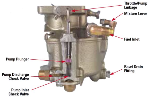 |
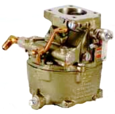
| Fig. 45. Marvel MA-4 Carburetor | Fig. 46. Marvel MA-4 Carburetor Cutaway |
The Marvel MA series carburetors are quite simple carburetors, differing from the Marvel-Schebler model TSX agricultural carburetors in the way the mixture is controlled, aluminum in place of cast iron construction, and the removal of a manual choke.
 |
| Fig. 47. Marvel Model TSX Agricultural Carburetor |
Skinners Union (S.U.) Float-Type Carburetors
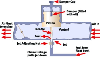
S.U. Carburetors used on automobiles have a suction-operated piston that moves a needle valve up or down to control the fuel–air mixture. The piston is the upper part of the variable venturi where the fuel drawn through the metering jet discharges into the airstream.
 |
| Fig. 48. S.U. Automotive Carburetor |
The actual throttle plate that regulates airflow into the engine is located between the intake manifold and the variable venturi. The suction in the intake manifold draws the fuel–air mixture into the manifold as the throttle opens. The suction in the volume between the throttle and variable venturi is the source for the operation of the variable venturi piston. This basic philosophy was the inspiration for the S.U. aircraft carburetor design. Note the similarity between the automobile and aircraft fuel metering jets and needles in Figure 49 (12 to 16). S.U. type Merlin A.V.T. 44/ 206 or 208 (anti "g") duplex double-entry carburetors were used on the Merlin 61 engine. The maximum fuel demand is 135 gallons per hour. The fuel, at fuel pump pressure, flows through an 8 ~ 10 psi reducing valve before entering the fuel supply connection (1) (Fig. 49).
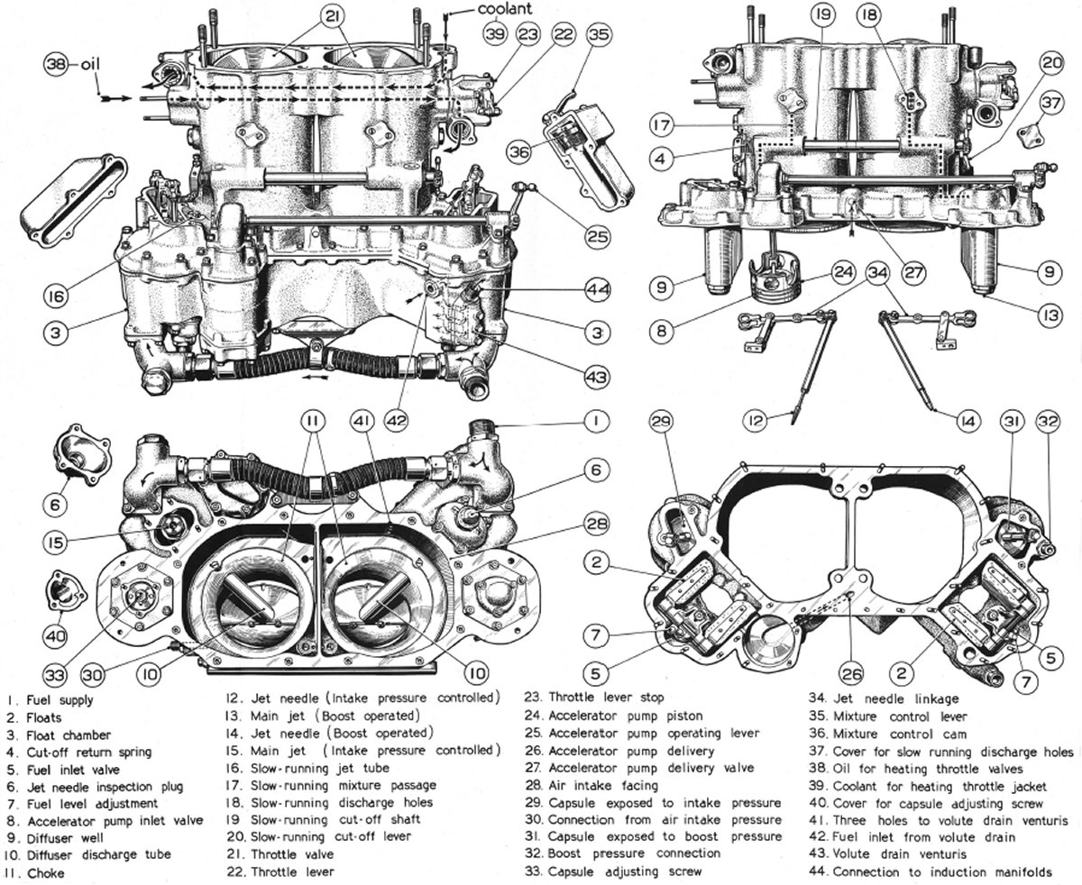 |
| Fig. 49. Skinners Union (S.U.) Carburetor Used on Rolls-Royce Merlin Engines |
Description
The complete carburetor assembly consists of two independent carburetors. Aneroid-operated jets automatically control the mixture. The port side of the carburetor incorporates a two-position mechanical jet control. The float feed mechanism is designed to operate at approximately nine psi, the fuel level adjustment being effected by turning the eccentrically two mounted screws (7). A throttle valve (21) is located above the choke or venturi tube (11) and has at its narrowest point the discharge end of a diffuser tube (10), chamfered on the upper side, leading from the diffuser chamber. This creates a pressure difference between choke and diffuser chamber due to air velocity (upwards) through the choke. The diffuser chamber also houses a main diffuser (9), lower part of a main jet needle (12 or 14), and a slow-running jet tube (16) submerged in the fuel. An annular air space around each choke is connected by a drilled passage to the float chamber (4) forming an air balance, and suitable points (8) for the main air bleed supplies. An air bleed type of diffusion is included for the slow-running device. Each main jet is in a well formed by a hole in the diffuser-securing nut. A main jet needle passes through the jet at the lower end of the diffuser chamber. This needle has a tapered end and is moved automatically to provide the correct mixture strength, controlled by an aneroid (29 or 31) and a connecting link. A guard tube inside the diffuser prevents the ingress of foreign matter that may restrict free movement of the jet needle. The main jet orifice control which regulates the flow of fuel to the diffuser well is in each case effected by an aneroid assembly (spring-balanced evacuated metallic capsule) having an upper extension connected to one end of a link (fulcrummed midway to a bracket), the other end being jointed to a needle tapered at its lower end. Move the capsule assembly up or downwards by the adjusting screw to adjust the jet needle.
Extensive tests have determined the graduation of the jet needles. Do not interfere with the shape of the needle in any way. Port side capsule (31) operates in a chamber, closed to atmosphere, but connected to boost pressure supplied by a flexible pipe (32) from the supercharger delivery side. Rise in boost pressure therefore causes a downward movement of the capsule stem and an upward movement of needle (14). As boost pressures raise to the region of the economical cruising range the carburetor functions as a fixed jet type, since the parallel part of the needle remains in the jet orifice. From this point onwards, the increased air velocity through the chokes creates a suction that draws fuel from around the diffuser lower holes, necessitating an increased fuel supply (jet). The tapered end of the needle rises to open the jet orifice as boost pressures increase. When a cockpit mixture control lever is fitted, it is connected to the lever (35), which operates a cam (36) (shown in the WEAK position) ensuring a positive position of jet needle (14). Should the boost pressure exceed the permissible figure while the cam is in the WEAK position for economical cruising, aneroid (31) will collapse and lift the jet needle (14) sufficiently to restore the mixture strength independently of the mixture control cam (36). Failure of the capsule results in the needle pushing down into the economical cruising position, weakening the mixture at boost pressures. Starboard side capsule (29) operates in a chamber connected to air intake pressure and extends upwards with decrease in pressure, thereby moving the jet needle (12) downwards, restricting the main jet orifice and weakening the mixture. Failure of the capsule will cause the needle to move, first into the WEAK position and finally into the RICH position. Intake air admitted at point (8) passes down the annular diffuser space through the small holes mixing with and atomizing the fuel, then passing through the main discharge nozzle (10).
The slow-running diffuser jet tube (16), immersed in the main diffuser well, has a metering-hole midway and small holes towards the upper end. These holes connect through passages leading to the three holes at the throttle edge, resulting in atomized fuel and air mixing in the diffuser chamber. As the throttle is opened, the air velocity falls in the slow-running system, but is increased around the main diffuser discharge tube (10), causing the main diffusion system to come into action. Three holes (18) are arranged, one above, one below, and one adjacent to the throttle edge, the latter being thickened to localize the throttle edge effect and prolong the change-over period. A cut-off valve (19) interposed in each slow-running passage enables the engine to be stopped immediately the ignition is switched off. Without this device, a hot engine may continue to fire erratically (due to incandescent valves, spark plugs, etc.), causing violent impulses that are detrimental to the engine and mounting. The cut-off valve (19) is operated by a lever (20) connected to the cockpit by a "pull" type control, the return to OPEN position being effected by a torsion spring around the cut-off valve shaft. Upon operation of the cut-off valve, switch off the ignition.
The port side carburetor is fitted with a triple venturi unit connected on the one hand with the supercharger volute (42), and on the other with a flexible pipe leading to the induction manifolds. This latter pipe under slow-running conditions transfers the low pressure in the induction manifolds to the air intake via the venturi (43), creating a high velocity through the latter and thus returning fuel from the supercharger volute to the induction manifolds. Heating the throttle jackets (39) with coolant returned from the main system and circulating scavenged hot return oil (38) via the hollow throttles and shaft prevents "Icing up" of the throttles. The throttle control lever (22) connects to one side of the boost regulator differential, and is shown on its slow-running stop (23). Movement of the cockpit throttle lever operates the accelerator pump (24) by lever (25). Opening the throttle moves the piston upward, transferring fuel from the port float chamber through the disc valve (28.) Closing the throttle moves the piston downward, forcing fuel from the pump chamber through the non-return valve (27) to holes drilled in each choke tube. This fuel allows rapid acceleration and "cutting" is prevented. A leak through the disc valve(27), under certain running conditions, draws additional fuel from the pump chamber through the discharge holes (26). This results in an increase in fuel consumption at the economical cruising mixture range. Connecting air intake pressure to the holes (26) by a passage removes this defect, thereby breaking down the depression without affecting normal working of the pump discharge.
Slow-running adjustment: Correctly adjust the slow-running system on a new engine before dispatch. Apart from the slow-running stop on the carburetor, set to give an idling speed of approximately 400 ~ 500 rpm, no other adjustment, i.e., by altering slow-running jet orifices, is advisable. Should the slow running, however, appear faulty, it may be due to long periods of standing, and in this case all jets and passages should be inspected and cleaned. When finally reassembled, the engine should be started and run until the oil and coolant temperatures are normal, and a check made to ensure that the throttles can be closed suddenly from about 1,400 rpm back to idling speed without cutting out or erratic firing.
Fuel level: With the carburetor positioned so that its upper joint face is horizontal and a suitable sighting tube coupled in place of one of the plugs in the jet needle wells, connect a fuel pressure supply of 100-octane fuel at 9 psi to the fuel inlet rail. Check that, at 10-psi inlet pressure, the dimension from the top of the float chamber face to the fuel level is between 0.510 ~ 0.635" on the A.V.T. 44/ 206 carburetor, or 0.350 ~ 0.450" on the A.V.T. 44/ 208 carburetor. Maintain the fuel pressure for 15 minutes to confirm that creeping is not taking place. Repeat the test for each float chamber. Should the fuel level in either float chamber not be within the above limits, or if it is found that creeping is taking place, it will be necessary to remove the carburetor lower half for inspection and adjustment. If the fuel pressure is too low or high, adjust the pump relief valve and spring on later type engines.
Jet needle settings: Altitude (R.H. side) needle should project 0.100" under the face of the jet nut at standard atmosphere (29.92 Hg) when the engine is cold. Boost operated (L.H. side) needle should project 0.410" below the face of the jet nut when the capsule is subjected to a boost gauge pressure of +9 psi. Make a correction for variation of the barometer, if necessary, when a U-tube is used. Drain the capsule chamber before applying the test. Make a dimensional check with the two-position cam control moved into the automatic rich position and the capsule chamber at normal atmosphere. The needle should then project 0.600". below the face of the jet nut. If there is no cockpit mixture control, the mixture control is always at the WEAK position in the carburetor. The parallel part of the jet needle should be at the point of passing through the jet orifice when a boost pressure of +6 psi obtains in the capsule chamber.
Priming is through a single connection mounted on the supercharger delivery, starboard side, and distributing from a flexible braided pipe to six nozzles in the induction manifolds. A filter is in the connection body. The distribution pipes on units with the volute drain, an arrangement whereby the supercharger volute is clear of liquid fuel, returns by venturi action to six points in the induction manifolds. A flexible braided pipe also conveys the fuel from the carburetor triple venturi assembly to the manifold main connection.
Service History:A common problem with float carburetors is the hollow brass float getting a pinhole or having a poor solder joint that allows the float to fill with fuel and sink. This opens the fuel inlet valve and floods the engine. Cork floats are subject "blistering" when the fuel-safe coating is attacked by compounds in the fuel, especially aromatics. The cork then gets soaked and sinks.
With few moving parts and only one jet S.U. carburetors tend to stay in tune for longer periods.
This page is a big help in understanding how S.U. carbs work.
A good video explains how the constant velocity carb works and why it works so well.
Send mail to
![]() with questions or comments about this web site.
with questions or comments about this web site.
![]()