A Brief History of Aircraft Carburetors and Fuel Systems
Part 10: Fuel Injection
by Terry Welshans
Bardstown, Kentucky
for the Aircraft Engine Historical Society
Published August 2013; Revised 24 Aug 2018
Table of Contents
Fuel injection was a well-known principle long before the First World War, as it was on the original Wright brothers' engine of 1904 and on the Antoinette aircraft engine prior to 1914. Fuel injection was always on diesel engines that used a fuel that evaporates only at the high temperature reached by the air compressed in the cylinder. Aircraft engines before the First World War used carburetors, primarily because they were lighter and simpler than fuel injection systems. In the United States, there were no attempts at aircraft engine fuel injection systems until well after the war, at about the same time as the first attempts at designing a new type of carburetor.
NACA Research
The origins of fuel injection are many. NACA started its investigation about 1927 in the hope of increasing engine efficiency by using plain air instead of the fuel mixture to clear cylinders of burned gases that remained from the previous cycle. This was only possible when the fuel and air supplied to the cylinder arrived separately. Early in the 1930s, NACA's fuel-injection research changed to determine the possibility of using "safety fuels". Safety fuel resembles diesel fuel in that they would only evaporate in the heat of the cylinder. The Navy had an interest in safety fuels, as they wanted to use them as fuel in its fleet of dirigibles.
The NACA program consisted of single-cylinder work in connection with the Allison engine, which the Navy wanted to use as an airship power plant. NACA investigated basic principles as well as possible efficiency improvements, the possibility of using safety fuels, the correct form of injection nozzles, the effects of varying fuel viscosity, and proper timing of injection. Most of this work used components furnished by the private firms that were developing fuel injectors, and there was no attempt made to develop a complete injection system. The results of the NACA research were of some value in developing injection systems, but unfortunately, NACA did no work on the critical fuel injection development problem — design and development of a suitable metering or control system. By 1954, The CAA required fuel injection on piston engines used by the airlines.
Other Fuel Injection Research
For the ideal gasoline direct injection engine, fuel injected directly into the cylinder as a very well atomized spray vaporizes completely by absorbing heat only from the in-cylinder air. This is also a very efficient mechanism for cooling the resident air charge inside the cylinder. If injection occurs during the induction process, the resulting decrease in charge temperature due to the fuel's latent heat of vaporization can yield an increased mass of air in the cylinder, thus increasing the volumetric efficiency of the engine. The reduced charge temperature at the start of compression also translates into lower compression temperatures, thus enhancing the mechanical octane number of the combustion chamber. Because of the thermodynamic effects of in-cylinder charge cooling, the ideal gasoline direct injection engine exhibits the advantages of both higher torque and a higher knock-limited compression ratio as compared to the port fuel injection engine.[154]
The cooling effect continues with fuel vaporization, even into the early stages of combustion; however, the fraction of fuel vaporizes by the time that induction completes is directly related to the gain in volumetric efficiency.[155] Intake charge cooling also modifies and improves the heat transfer process, particularly for the early injection that is associated with high-load operation. The charge density increases during the compression stroke, and charge temperature is elevated to values higher than cylinder wall temperature, with heat transferring to the walls. Retarding the injection timing toward the end of the intake stroke rapidly diminishes this heat transfer advantage.[156]
A stoichiometric air-fuel ratio produces charge cooling that has the effect of lowering the air temperature at the end of induction by approximately 20°C. As a result, even under wide-open throttle operation at low engine speed, the gasoline direct injection test engine exhibited a 6% higher power output as compared to that of a port fuel injection engine. Higher intake manifold absolute pressure improvements attributed in part to the improved charging efficiency. Another contributing factor is the ignition-timing advance made possible by the reduced knock tendency.[157]
Injector Spray Pattern
It has been demonstrated that, in spite of decades of continuous development on diesel multi-hole injectors, that these nozzle-type injectors are generally poor choices for gasoline direct injection applications. A multi-hole nozzle used in a gasoline direct injection engine application results in an unstable flame kernel when ignited by a single fixed spark plug. The rich mixture zones are close to the lean mixture zones; thus, the flame front does not propagate uniformly through the combustion chamber.[158] Hole distribution is effective in ensuring good spray dispersion and reliable flame propagation between the spray plumes, and generally provides good engine performance. Fujieda studied the effect of the cone angle of individual spray plumes on direct injection engine performance.[159] Eventually, continued development and testing led to a satisfactory multi-hole gasoline direct injection injector similar to that used in diesel engines. With an increase in the spray cone angle, the lean limit extends, due to the improvement in air utilization. It was also determined that reducing the nozzle flow area and/or increasing the number of holes can achieve the same purpose.[160]
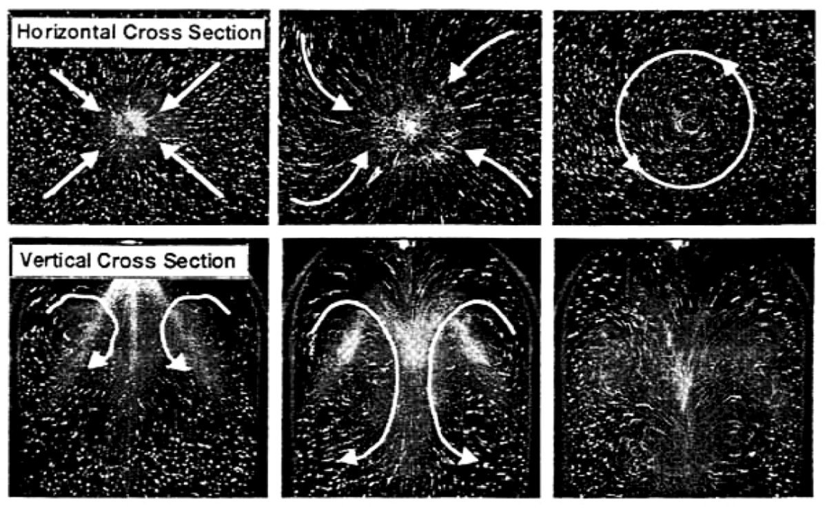
Currently, the most widely utilized gasoline direct injection injector is the single-fluid, swirl-type unit that utilizes an inwardly opening needle, a single exit orifice and a fuel pressure in the range from 5.0 to 10 mPa (725 ~ 1,450 psi). This general configuration is conceptually a multi-hole nozzle with an infinite number of holes, with a uniform distribution of the fuel around the cone circumference. Consequently, it is best to minimized wall impingement at full load for an appropriate injector position and spray cone angle.[161] The design of the needle-type, swirl-spray injector is a strong rotational momentum given to the fuel in the injector nozzle. The swirl adds swirl momentum to the axial momentum. In a number of different nozzle designs, liquid flows through a series of tangential holes or slots into a swirl chamber. The liquid emerges from the single discharge orifice as an annular sheet that spreads radially outward to form an initially hollow cone-shaped spray pattern.[162] The initial spray cone angle may range from a design minimum of 25° to almost 180°, depending on the requirements of the application, with a delivered fuel spray mean droplet diameter ranging from 14 to 25 μm. In the swirl-type injector, the pressure energy changes into rotational momentum, enhancing atomization. Moreover, the spray mass distribution of a swirl-type injector is generally more axisymmetric than that obtained without swirl.
|
| Fig. 103. Gasoline Fuel Injection Nozzle Swirl Spray. In the case of reduced ambient pressure during early injection, the fuel spray has a wide, hollow cone-shaped structure. In the case of higher ambient pressure, the higher drag force changes the spray into a narrower, solid-cone shape.[163] |
 |
 |
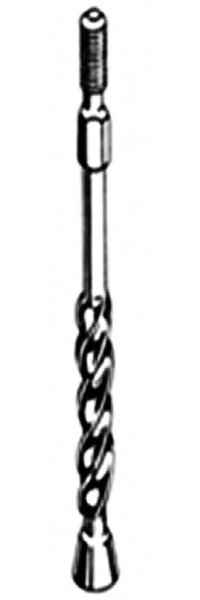 |
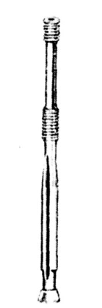
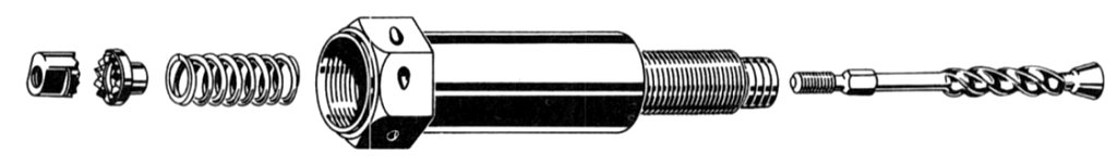
| Fig. 104. Bendix Gasoline Injector Pintle |
Fig. 105. CECO Injector Pintle |
Fig. 106. Bendix Direct Injector Pintle |
The difference in the design of the pintle found in Bendix and CECO fuel injector valves is primarily the helix near the bottom of the CECO design. The helix induces swirl into the spray pattern.[164] Sometime later, the new Bendix direct injectors received a pintle with a helix.
Fuel Injector Companies
Robert Bosch GmbH
Robert Bosch GmbH developed fuel injection systems for Daimler Benz engines in World War II. After World War II, Bosch remained in the automotive diesel and gasoline fuel injection business.
American Bosch
Robert Bosch formed the American Bosch company as the Bosch Magneto Company in the United States in 1906. Before World War I, 88% of Robert Bosch Company's sales were outside of Germany. When the United States entered WWI, the American government expropriated the Bosch Magneto Company, complete with its patents and factory. A group of investors then bought the company, renaming it The New American Bosch Magneto Company (ABMC). Although the products carried the Bosch name, the products did not meet Robert Bosch's standards.
In 1921, Bosch founded the Robert Bosch Magneto Company Inc.to distinguish its products from ABMC's. The products bore the armature in a circle as its trademark, along with "Germany." By 1927, Bosch developed the Bosch diesel injection pump. Bosch built its first diesel automotive system by 1936. In 1954, Bosch developed an automotive gasoline fuel injection system.
By 1930, the patent issue was resolved, and an agreement reached where the German company would label their products with the trademark "Bosch", and ABMC would label their products as "American Bosch." In 1930, Robert Bosch purchased a portion of American Bosch. The two companies merged in 1938, when it became the American Bosch Company. In the early part of World War II, the American government expropriated the company. In 1953, Robert Bosch opened an office in New York, and with the new name Robert Bosch Corporation. In 1983, the Bosch Group regained its trademark and the unrestricted use of the Bosch name. American Bosch became AMBAC International Corporation, specializing in automotive ignition products. Bosch entered the injection pump and nozzle business for diesel and gasoline vehicles.
Eclipse (Bendix)
The Eclipse division of the Bendix Corporation was involved in fuel injection development under the direction of Frank Mock. Bendix used Bosch fuel injection nozzles before developing its own. When the need for large reciprocating engines wound down, Bendix produced after-market fuel injection systems for reciprocating engines under 1,000 hp as the RS series units.
Marvel
Marvel hired M. G. Chandler in 1929 to supervise the development of a fuel injection system that he had patented. The US Army purchased a nine-cylinder unit tested on a Pratt & Whitney R-1340 Wasp, a Wright Conquer and an R-1820 Cyclone. In 1929, Marvel became part of the Borg-Warner Corporation.[165] Today, Marvel manufactures fuel injection systems for small aircraft engines.
Niles Bement Pond
Near the end of World War II, NBP's Chandler Evans (CECO) hydro-metering carburetor became a fuel injection system used on Boeing's B-29 bomber. The Bendix fuel injection system was favored over the CECO injection system, and replaced it in most applications. CECO continued development of fuel management systems into the jet age, and today, after a number of mergers and divestments,remains a major source of turbine engine fuel controls.
The injection carburetors built by Bendix Stromberg and CECO used a nozzle placed at the "eye" of the engine's supercharger. This placement eliminated ice caused by fuel evaporation. Several modifications in the nozzle and the supercharger were necessary to obtain an even distribution of fuel to all cylinders. The uneven distribution resulted in some cylinders receiving a leaner mixture, often leading to preignition or unsustainable cylinder head temperatures.[166] The only way to correct this issue is to inject the fuel directly into the cylinder head, and for an 18-cylinder engine, that takes two nine-cylinder timed pumps, high-pressure fuel lines and injection nozzles.
Bendix RS and RSA Fuel Injection
Bendix Stromberg produced the RS series fuel injection systems, which use a flow divider to proportion a constant stream of metered fuel to injection nozzles at the intake manifold port of each cylinder. This series includes the RS and RSA systems, in sizes to fit 300 ~ 1,000 in³ engines. The operating principle is similar to that of the Bendix PS series injection carburetors. Instead of the metering valve discharging into the intake manifold immediately beyond the throttle valve, the fuel flows to the flow divider where it branches to each cylinder's intake port. This provides a continuous flow of fuel, not timed to the cylinder in any way.
 |
 |
| Fig. 107. Bendix RSA Fuel Injection System Body | Fig. 108. Bendix RSA Flow Divider |
Continental Fuel Injection
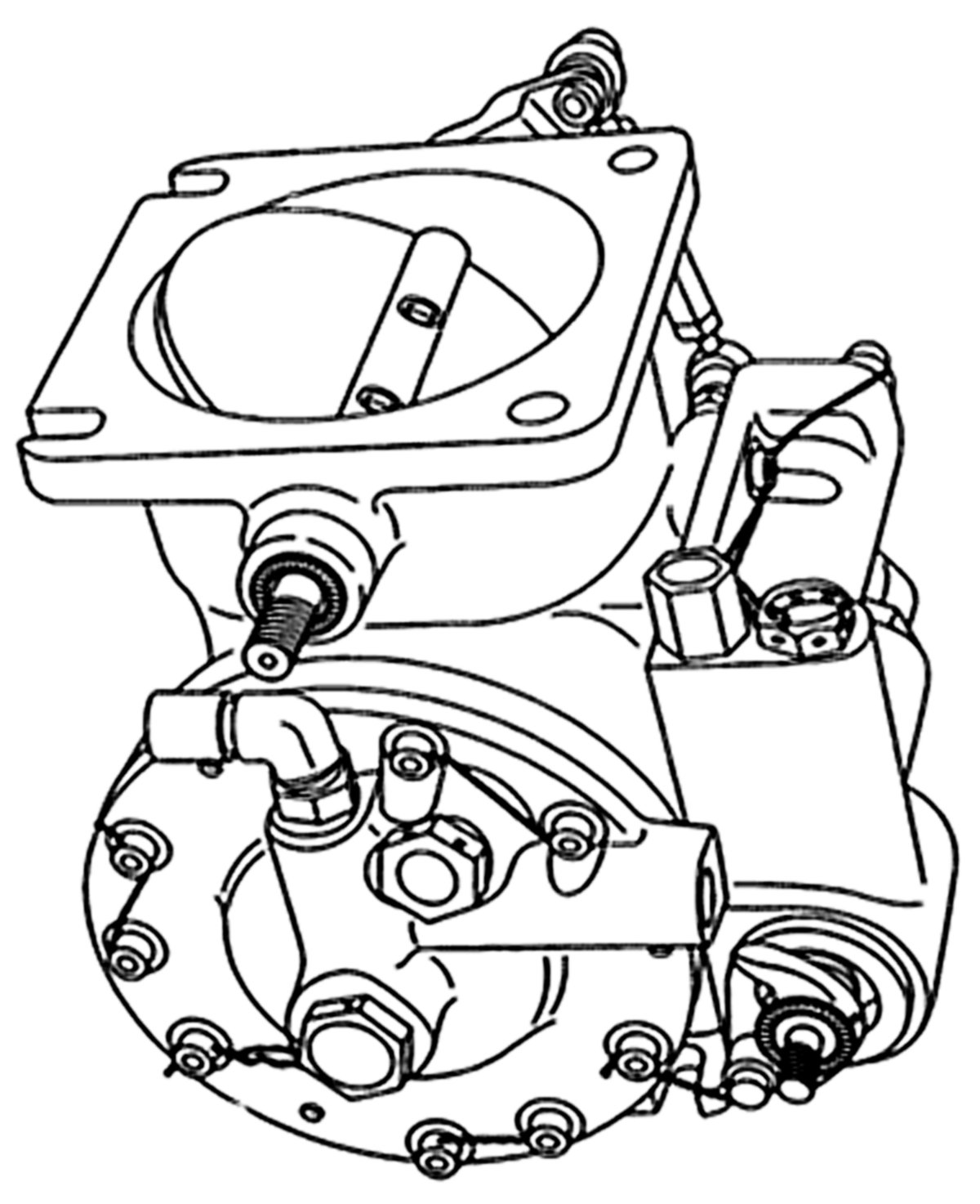
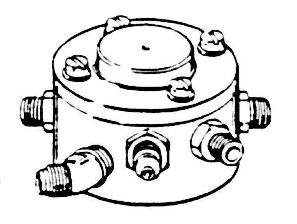
Continental installed a very simple fuel injection system on the IO-470F engine installed in Cessna 185s. This system had no air measurement mechanism other than a mechanical linkage between the throttle shaft and the fuel-metering valve. Throttle position alone determined fuel flow to a flow divider located on top of the engine crankcase between the number three and four cylinders. This fuel injection system is a simple, low-pressure system of injecting fuel into the intake valve port in the cylinder head. This multi-nozzle, continuous flow-type system controls fuel flow to match engine airflow. Any change in throttle position, engine speed, or a combination of both, causes changes in fuel flow in the correct relation to airflow. A manual mixture control and a fuel flow indicator provide the pilot a method for leaning the fuel-air mixture at any combination of altitude and power setting. The injection system uses a typical rotary-vane fuel pump.
This unit occupies the position ordinarily used for a carburetor, at the intake manifold inlet. The function of this unit is to control engine air intake and to set the metered fuel flow for proper fuel-air ratio. There are three control elements in this unit, one for air and two for fuel, one of which is for fuel mixture and the other for fuel metering. Fuel enters the control unit through a strainer and passes to the metering valve. The position of the metering valve controls this fuel for delivery to the manifold valve and nozzles. A linkage connecting the metering valve to the air throttle proportions airflow to fuel flow. The position of the mixture valve determines the amount of fuel returned to the fuel pump. A shroud encloses the fuel control portion of the fuel-air control unit. The enclosure is blast-air cooled to help prevent vapor lock.
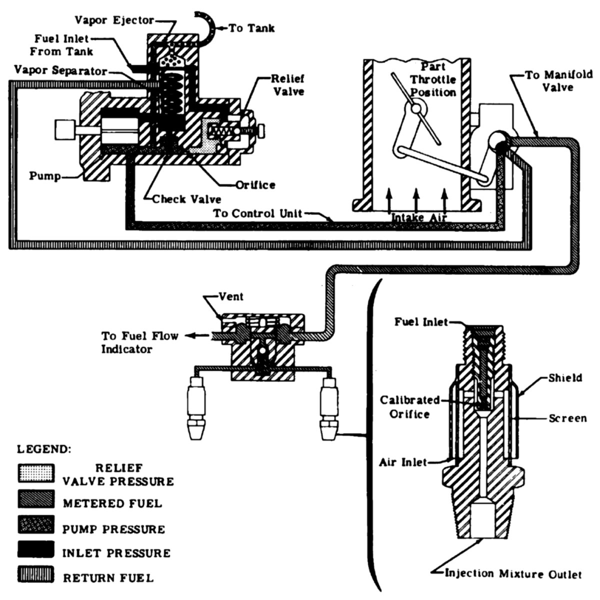 |
| Fig. 109. Continental Fuel Injection System |
Direct fuel injection differs from manifold injection systems in that the fuel injection nozzle sprays fuel into the combustion chamber instead of the supercharger or intake valve port. Direct injection sprays fuel into the combustion chamber just prior to ignition; other injection systems have a constant fuel flow that mixes with air entering the combustion chamber at some point between the supercharger inlet and the individual cylinder intake valve.
Bendix Stromberg Direct Fuel Injection System
Bendix Models 58-18-A1A, 58-18-B1A and 58-18-C1A
All services used the manufacturer's model 58-18-A1A, 58-18-B1A or 58-18-C1A designation.
The "58" indicates the area in square inches of the flange opening to which the master control attaches.
The "18" designates the number of cylinders on the engine on which the system is mounted.
The "A," "B" or "C" identifies the system type and indicates major changes in the system.
The "1" indicates changes that do not affect part interchangeability.
The final "A" indicates that Bendix Products Division manufactured the system.
The Stromberg direct fuel injection system used on Wright R-3350 series engines consists of three major sections — the master control, two 9-cylinder injection pumps, and 18 individual cylinder head discharge nozzles.
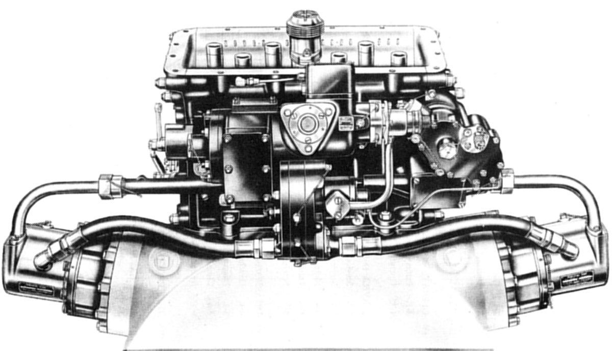 |
| Fig. 110. Bendix Stromberg 58-18-A1A Direct Fuel Injection System |
General Description
The Stromberg direct injection system operates in the same way as the Stromberg injection type carburetor except that two fuel injection pumps replace the carburetor discharge nozzle. The fuel injection pumps receive fuel from the regulator and fuel control unit that mounts on the throttle body, and divide the total fuel flow into equal amounts for the number of cylinders involved. The pump also acts to increase fuel pressure at individual fuel nozzles to between 500 and 2,000 psi, the pressure required to force the fuel through the nozzles.
In the Stromberg direct injection system, the master control unit is a combination of throttle body, fuel control unit and regulator. There are two high-pressure fuel injection pump assemblies. The fuel delivered from the fuel injection pumps flow to the individual cylinder nozzles through high-pressure lines. The injection period occurs during the normal intake stroke of the cylinder. The start of the injection period varies but the end occurs at a predetermined crankshaft position near bottom dead center of the intake stroke.
The master control is very similar to the Stromberg "PR" series injection carburetors; the important difference being that the metered fuel from the fuel control unit is piped directly to the injection pumps instead of to the usual single discharge nozzle or discharge bar. All master controls are convertible into a standard injection carburetor configuration. When combined with an adapter unit and a few other additional parts, the converted unit will successfully operate an engine. A new type porous bronze fuel strainer replaces the wire mesh-type strainer.
 |
| Fig. 111. Bendix Stromberg Direct Injection Schematic |
The two injection pumps are timed fuel distributors, as they accurately divide the total quantity of fuel delivered by the master control into equal parts, and deliver the equally divided parts to the engine cylinders at high pressure, through discharge nozzles screwed into the cylinder heads. High-pressure, stainless steel injection lines connect injection pump to the cylinder head discharge nozzles. The nozzles open when the pressure in the injection lines is great enough to overcome the force of the nozzle spring, spraying fuel into the engine cylinders during the intake strokes. Vapor is eliminated from each pump through a vent float and valve system in a housing in the top of the pump control shaft housing. A cage holds the float in place and allows the float to move up and down as the fuel level in the pump rises or falls. A weight in the bottom of the cage forces the float to close the valve if the airplane goes into an inverted position, thus preventing fuel from draining from the pumps through the vapor vent outlets. Engine oil lubricates the driving mechanism of each pump. The oil flows through a channel in the mounting flange, through the lower driving mechanism, and drains back through the bearings into the engine oil sump.
 |
| Fig. 112. Bendix Stromberg Direct Fuel injection System Detailed Schematic |
This system is a dual-pump installation and pump synchronization is very important. This is achieved by adjusting the position of a bypass control plate that controls the output position of each bypass. An external lever on each pump, in conjunction with the pump control diaphragm, controls the position of the bypass control plate. These two levers are connected through a link rod that, when properly adjusted, synchronizes these two external levers and, in turn, the position of the bypass control plates. This link rod is not in any way connected with the pilot's controls.
Principles of Operation
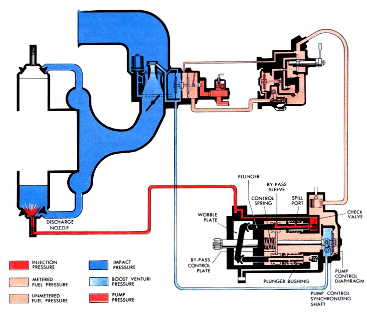
The master control meters fuel into the fuel pumps in the same manner as the pressure-type carburetor meters fuel to the discharge nozzle. At idling speeds, the idle needle valve regulates the fuel flow. At cruising and high speeds, airflow through the venturi controls the fuel flow. The setting of the manual mixture control and the action of the automatic mixture control affect the fuel flow to the injection pumps. At high power output, the power enrichment valve opens to supply extra fuel. Although the drawing shows only one pump, there are two pumps in this system. Both pumps receive fuel from one master control.
 |
| Fig. 113. Bendix Stromberg Direct Injection Pump Schematic |
In the sectional view of the injection pumps, note the wobble plate on the drive shaft. Note also the spring on each plunger, which holds it against the wobble plate. As the drive rotates, plungers move in and out – forced to the right by the wobble plate and returned by the spring. This pumping action forces fuel, received from the master control, into high-pressure lines connected to the pump-mounting flange and leading to discharge nozzles.
Bendix Stromberg Model 58-18-A2B Gasoline Injection System
General Description
 |
| Fig. 114. Bendix Stromberg Model 58-18-A2B Gasoline Injection System |
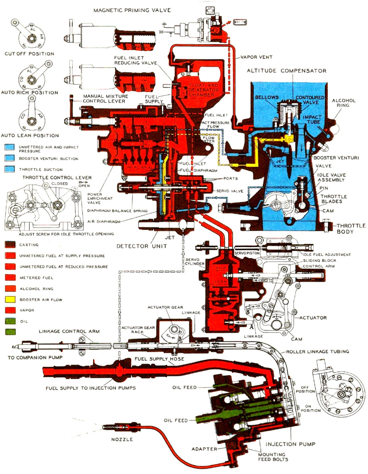
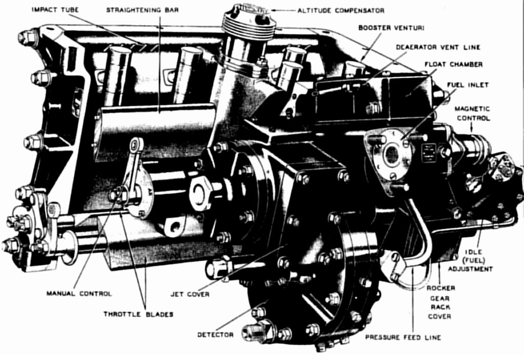
The Model 58-18-A2B gasoline injection system controls fuel metering and injection of specific quantities of gasoline directly into the combustion chambers. It consists of the following major components: Master Control, Altitude Compensator, Detector, Actuator, Injection Pump(s), and Injection Nozzles.
The MGA58A4 Master Control unit mounts on the engine's rear section in place of a carburetor. The unit controls the amount of gasoline delivered by the injection pumps to the engine. The quantity of gasoline delivered by the injection pumps is in proportion to the quantity of air entering the induction system. The master control consists of four main assemblies, which are the altitude compensator, the throttle body, the detector and the actuator.
 |
| Fig. 115. Bendix Stromberg Fuel Injection Master Control Unit |
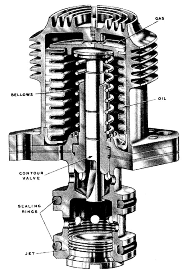
The Altitude Compensator is an aneroid type unit that actuates a contoured needle valve to compensate for changes in air density at the air inlet. The air at a higher altitude is less dense and weighs less per unit of volume due to decreased air pressure. The altitude compensator automatically corrects for the change in the air density, as the airplane operates through a wide range of altitude and temperature changes. Special oil partially fills the space between the bellows and the housing.
The Detector receives the corrected pressure drop as altered by altitude compensator and transform it into a direct physical force that acts upon the servo-valve. The physical force is not sufficient to directly operate the fuel control of the injection pumps and needs amplification through additional means. A large flexible diaphragm transforms the corrected pressure drop into a direct force that acts upon the valve. The diaphragm and attached servo-valve move right or left according to the air pressure difference on the diaphragm. Fuel flow through the jet in the unit places a pressure drop across a second diaphragm, which is used to exactly balance the pressure drop across the first diaphragm. Tubes connect the servo-valve and servo-cylinder where fuel inlet pressure actuates the servo-valve piston.
The Actuator mechanism transforms servo-piston movement into control lever movement. When the throttles opens, the fuel control levers also open through the actuator linkage and cam. At idle speed, airflow through the venturi does not produce sufficient pressure drop or metering force to control the system properly. For this reason, the cam provides a definite relation between the throttle movement and pump fuel control levers. Within this region of operation, the cam and the connecting linkage determine the fuel-air ratio.
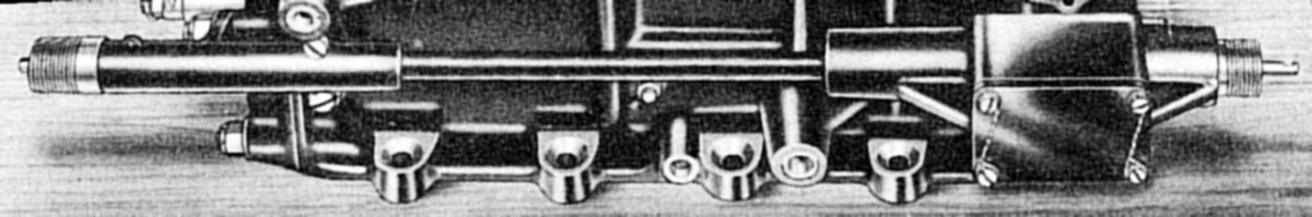
The Injection Pumps PGA9100A3-4 and PGA9100A4-4 are 9-cylinder swash plate actuated, flange mounted, constant stroke, lapped plunger type units, designed to supply controlled quantities of fuel to nine cylinders of an engine. Certain 18-cylinder engine installations have a combination of both of the above types of pumps. The cutaway view of the pump shows the inner portion of the pump and the important parts of the unit. The two injection pumps receive metered fuel from the master control and equally distribute this fuel to the engine cylinders. This fuel is in the injection pump reservoir until it flows through the fuel intake port into the chamber above the lowered plunger. The position of the helix of the plunger in relation to the fuel intake port determines the amount of fuel delivered by the pump. For hydraulic balance, the plungers of the injection pump have twin helices. The movement of the control shaft lever controls the position of the helix in relation to the intake port, and changes the quantity of fuel delivered. All plungers within the pump receive lubrication from the dual lubricating system incorporated within the pump. An internal system lubricates the lapped plunger section, the lower seat rings, swash plate, plunger balls, etc.
The Fuel Injection Nozzle in each cylinder head sprays fuel directly into the combustion chamber just before the spark plugs fire.The nozzle is a poppet type valve that opens hydraulically from the pressure of gasoline delivered to it from the injection pumps. Gasoline is discharged at a 30° included angle of spray. The pump delivers pressurized metered gasoline to injection nozzles that opens at a pressure of 480 to 520 psi. At this pressure, the poppet valve remains open, ejecting a fine, even, constant spray into the engine cylinder head. At reduced pressure, the poppet valve closes, preventing further injection of fuel.
 |
 |
 |
| Fig. 116. Bendix Stromberg Altitude Compensator Cut Away | Fig. 117. Bendix Stromberg Fuel Injection Detector | Fig. 118. Bendix Stromberg Fuel Injection Actuator |
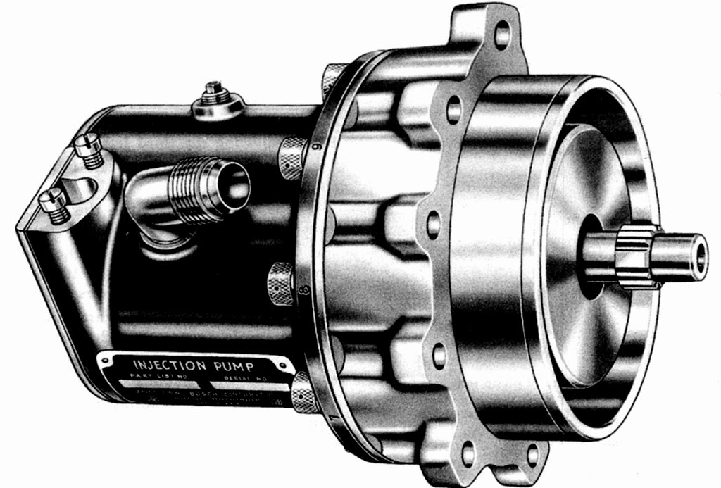 |
 |
 |
| Fig. 119. American Bosch Injection Pump | Fig. 119a. Bendix Stromberg Injection Pump | Fig. 119b. Bendix Stromberg Injection Pump |
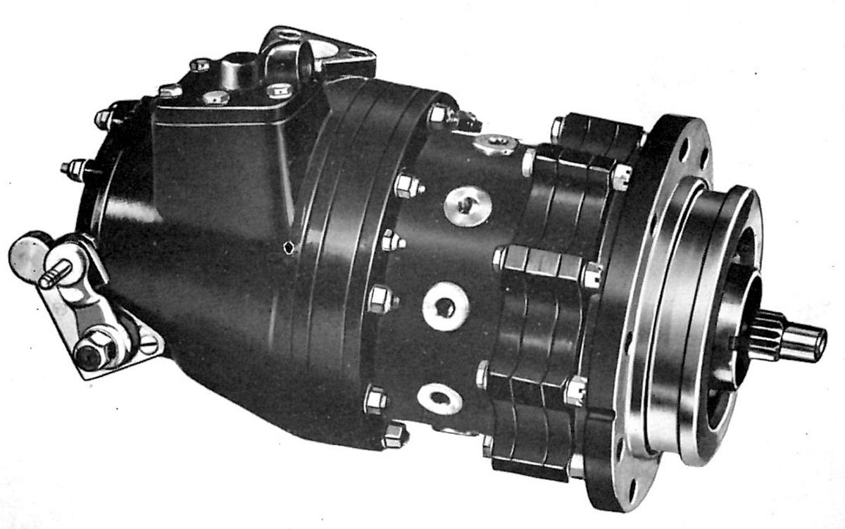
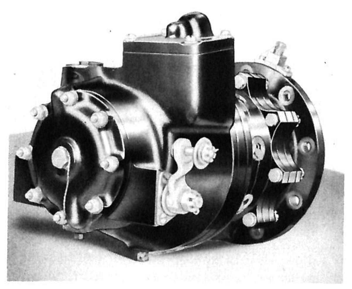
 |
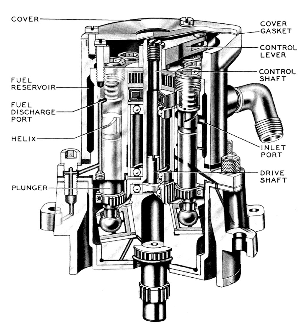 |
 |
| Fig. 119c. Bendix Stromberg Injection Pump | Fig. 120. American Bosch Injection Pump Cut Away | Fig. 121. Direct Fuel Injection Nozzle |
Principles of Operation
The Master Control throttle body inside surface is formed in the shape of a venturi. This provides a pressure drop for any given airflow. An additional pressure drop across the booster venturi is proportional to the velocity of the air flowing through the throttle body. This compensated pressure drop is the fundamental metering force that controls the detector servo-valve.
Altitude Compensator bellows react to air pressure changes due to altitude, and change the position of the contoured compensator valve. The unit corrects the primary metering force in proportion to the density of the air flowing through the throttle body. A change in temperature also causes the bellows to expand or to contract, thereby also changing the position of the contoured valve. The compensated pressure drop connects through internal passages to the detector.
The Detector converts Altitude Compensator pressure into fuel servo valve movement. With the engine operating at a given condition, and the throttles are opened further, airflow through the throttle body increases, resulting in an increased differential across the impact tubes and the booster venturi. This pressure connects to the air diaphragm, causing the diaphragm to move to the right, moving the servo-valve to the right, uncovering the port. Inlet fuel pressure then enters the servo-valve through the open port to the servo-cylinder. Increased pressure at this point moves the servo-piston toward the rich position and through the mechanical linkage moving the control levers of the injection pumps for increased fuel delivery. This increased fuel flows through jets, resulting in an increased pressure drop across the fuel diaphragm, closing the port. The increase in airflow will always cause a proportional increase in fuel flow until the two diaphragms are in balance. The system remains on this point until some further change in airflow occurs. When the throttles are closed, the reduction in differential causes diaphragm movement to the left, with a corresponding reduction in fuel delivery. The manual mixture control lever leans the fuel-air ratio for cruising, and shuts off the fuel to stop the engine. There is an indicator marked for the three positions,"AR" (auto-rich), "AL" (auto-lean) and "CO" (cut-off).
The Actuator must be pre-set before starting the engine by opening and closing the throttle three times. Through the throttle cam and connecting linkages a positioning pump in the actuator system move the servo-piston, pump control linkages and pump capacity control levers to full delivery position. This action assures ample fuel delivery to the engine for starting and eliminates need for priming. At idle speed, airflow through the venturi does not produce sufficient pressure drop or metering force to control the system properly. For this reason, suction from below the throttle connects to the left side of the air diaphragm at idle through the action of an idle enrichment valve. This suction causes the diaphragm and connecting servo-valve to move to the left, opening the port to move the servo-piston to full lean position. In the idle range, there is no further movement of the servo-piston and the throttle cam and connection linkage actuates the pump control levers.
American Bosch Injection Pumps mount on either side of the supercharger's rear housing. A swash plate assembly actuates the plungers. Each of the nine plungers has two diametrically opposite helical reliefs. Two diametrically opposite inlet ports supply fuel to each plunger cylinder. These inlet ports draw fuel from an annular sump around the plunger housing. On the delivery stroke, the plunger closes the inlet ports, trapping the fuel in the pump cylinder, forcing it through a delivery valve into the injection line to the nozzle. The amount of fuel delivered by each stroke of the plunger depends on the time interval between the closing and opening of the inlet ports. Rotation of the plungers varies the rate of fuel output by changing the relation of the helix and the inlet port. To obtain uniform delivery characteristics from each plunger, the ball rods have gear segments that mesh with a master gear. The control lever is actuated by the pump linkage rotates the master gear shaft. Proper indexing of the gear segment with respect to the helix controls individual plunger discharge. Proper synchronization of the two pumps controls row-to-row fuel distribution. The spring-loaded delivery valves act as check valves to prevent loss of line pressure during the return stroke of the plunger. Pressure lubrication is supplied the lower portion of the plungers from an oil hole in the pump adapter flange. The swash plate bearing is pressure lubricated through the pump drive shaft.
The Injection Nozzle opens at a pressure of 480 to 520 psi. At this pressure, the poppet valve remains open, ejecting a fine, even, constant spray into the cylinder head of the engine. At reduced pressure, the poppet valve closes, preventing further injection of fuel.
Endnotes
[154] Automotive spark-ignited direct-injection gasoline engines, pp 494-495
[155] Automotive spark-ignited direct-injection gasoline engines, pp 494-495
[156] Automotive spark-ignited direct-injection gasoline engines, pp 494-495
[157] Automotive spark-ignited direct-injection gasoline engines, pp 494-495
[158] Automotive spark-ignited direct-injection gasoline engines, p 447
[159] Automotive spark-ignited direct-injection gasoline engines, p 447
[160] Automotive spark-ignited direct-injection gasoline engines, p 447
[161] Automotive spark-ignited direct-injection gasoline engines, p 447
[162] Automotive spark-ignited direct-injection gasoline engines, p 447
[163] Automotive spark-ignited direct-injection gasoline engines, pp 448-449
[164] Publication AN 03-CA-1, p 80 and Publication AN 03-10C8-1, p 104
[165] Development of Aircraft Engines, pp 267-283
[166] NACA Memorandum Report No. E6C25
Send mail to
![]() with questions or comments about this web site.
with questions or comments about this web site.
![]()