A Brief History of Aircraft Carburetors and Fuel Systems
Part 2: Introduction to Carburetion
by Terry Welshans
Bardstown, Kentucky
for the Aircraft Engine Historical Society
August 2013
Table of Contents
At the turn of the 20th century, internal combustion engines were heavy, low-power machines suitable for ships, industrial and automotive uses. As such, the carburetors of that time were comparatively primitive, troublesome devices.[6] Several early carburetor patents indicate that there was little known about how to determine and mix the exact amount of fuel necessary to match the needs of the engine under all of the service conditions encountered.[7]
A carburetor serves but one purpose - delivering the correct mixture of fuel and air to the engine cylinder.[8] This seems to be an easy job, but at the time, under the actual operating conditions, there was little understanding about fuel–air mixtures, without regard to the new conditions encountered in flight. Manually adjusting a carburetor to the best setting for any single steady engine speed is easy, but once perfectly set, any change in operation or the environment will require additional calibration.[9] In the history of carburetors, the earliest type of carburetor consisted of a simple, plain jet screwed into the induction pipe. As the air enters the induction pipe from the suction of the engine, a certain amount of fuel mixes with it, and this mixture passed into the engine. This method made the engine very hard to start, and had exceedingly bad acceleration and low efficiency when running at high speeds.[10] Generally, the higher the engine speed, the richer the mixture became. This additional fuel caused the combustion process to add heat to the engine faster than it dissipates, resulting in the engine overheating. It also made fuel consumption very high. Eventual discovery found that an efficient carburetor must first supply a rich mixture to an engine that would first permit easy starting and then provide the correct mixture at all speeds ensuring even acceleration and low fuel consumption.[11]
Many methods and designs were tried and tested, and each met with some degree of success, a few had good success by developing new features, and a few reached a point where they could be trusted to operate for extended periods without the usual constant adjustment and frequent breakdowns. One early design theory was saturating the intake air stream with fuel as it evaporated from the surface of a fuel bowl.[12] This method did not deliver very good results, as fuel saturated air is seldom properly correct. A modified design included an orifice that drew air up into the fuel bowl, creating bubbles of fuel-saturated air that mixed into the flow of engine intake air. As the orifice had an adjustable tapered pin to control the amount of air passing through the orifice, some control over the fuel–air ratio was possible. A later innovation was to move the tapered pin in and out of the orifice through a linkage that was connected to the throttle, resulting in a reasonably variable fuel flow that followed engine speed.[13]
The next development was a design that incorporated a venturi through which the intake air passed. A venturi is a reduction of the area of the intake air passage within the carburetor. The air moving through the carburetor must increase its velocity as it moves through the venturi to maintain the same volume of air entering and leaving the carburetor. The increase in velocity through the venturi results in a lower pressure, as explained by Bernoulli’s equation. This lowering of pressure roughly follows the velocity of the airflowing through the venturi. The reduced pressure within the venturi creates a suction that draws fuel into the airstream. The introduction of a venturi as a source of data about how much air is flowing through the carburetor was a major step in controlling the fuel–air mixture.
The purpose of an aircraft power plant is the conversion of the energy available in liquid hydrocarbon fuel into mechanical energy. The primary requirement for spark ignition engines is that, under the conditions existing in the engine combustion chambers, the gasoline should burn smoothly without exploding. The smooth, controlled pressure increase in the combustion chamber results in the maximum conversion of chemical energy to mechanical energy.[14] The essential process in the operation of reciprocating internal combustion engines is the non-continuous burning of a pre-mixed fuel–air charge in a chamber that allows the gas pressure created during combustion to act against a moving piston. Normal combustion in spark ignition engines commences with a spark igniting the fuel–air mixture, followed by the steady propagation of the flame front through the combustion chamber. The ratio of the fuel–air mixture, the timing of spark ignition, the temperature of the fuel–air mixture in the combustion chamber and the magnitude of combustion chamber pressure are the four critical variables that determine satisfactory engine operation.[15]
Combustion cannot happen if the fuel-air mixture is too lean (too little fuel) or too rich (too much fuel). Typically, gasoline will burn if it is mixed with air in a ratio of one part fuel (by weight) and with between eight and eighteen parts of air (by weight). These ratios express the lean and rich flammability limits for gasoline–air mixtures. Because the mixture delivered to each engine cylinder may vary, one or more cylinders may be closer to the lean mixture flammability limit and will misfire before other cylinders fire. "Scattered" misfiring results in a rough running engine and imposes limits on engine operation, often called the lean misfire limit.[16]
The chemically correct ratio for complete combustion of the reactants (known as the stoichiometric ratio) is approximately one part fuel to fifteen parts air. Satisfactory spark ignition and flame propagation depends on the ratio of fuel to air being close to the stoichiometric ratio. Studies of engine performance have found that the maximum power output from an engine occurs with a slightly richer mixture. Under those conditions, no oxygen remains when combustion ends. However, as there is an excess of fuel, the unburned fuel is wasted. In this example, the engine develops maximum power at the expense of fuel economy. A lean mixture results in maximum economy. No fuel remains when combustion ends, gaining economy at the expense of some power reduction. Each phase of flight requires mixture adjustment to meet the engine's needs for that phase of the flight.[17] Under these conditions, the excess atmospheric oxygen combines with nitrogen, creating various oxides of nitrogen, known as NOX. NOX contributes to air pollution and is a component of photo-reactive haze (aka smog.)[18] Do not confuse NOX, the encompassing term for all of the combinations of nitrogen and oxygen, with nitrous oxide (NO2), which is just one specific combination of nitrogen and oxygen.
One feature of lean fuel–air mixtures that has an impact on engine operation is the flame propagation speed. Mixtures leaner than the stoichiometric ratio burn more slowly and have a lower maximum temperature than the stoichiometric mixture. Combustion of lean mixtures may result in flame propagation that is still occurring when the exhaust valve opens. This can cause valve overheating (overheated valves may then lead to other combustion abnormalities). At the leanest mixtures, flame propagation may be so slow that a flame may be lingering in the combustion chamber when the inlet valve opens to admit a new fuel–air charge, resulting in ignition of the fuel–air mixture in the intake manifold, known as backfiring.[19]
The first aircraft engines created a new class of problems for both engine and carburetor designers, beyond those of surface-bound vehicles. The primary problems were the poor understanding of the pressure, temperature, humidity, air density, and the speed that these factors change while in flight. In 1918, the Bureau of Standards for the National Advisory Committee for Aeronautics performed a series of engine performance tests. The purpose of the tests was to determine the change in atmospheric temperature and pressure at various levels above the earth’s surface, with special reference to the variables affecting the functioning of the carburetor and the changes in performance resulting from the variables within the carburetor itself.[20] The report, published as Technical Report No. 48 in the NACA Fourth Annual Report, titled Carbureting Conditions Characteristics of Aircraft Engines, by Percival S. Tice. This work resulted in the following conclusions:
A second investigation made by the Bureau of Standards between October 1919, and May 1923, reported in the 10th NACA Annual Report of 1924 as Technical Report No. 189, Relation of Fuel–air Ratio on Engine Performance , by Stanwood W. Sparrow, answers to the following questions:[21]
The report concluded that:
Fuel–Air Ratio Versus Engine Power
Pounds are the unit used in fuel-air mixture ratios, not cubic feet or gallons. The ratio may be expressed as either "a pound of fuel to so many pounds of air" or as "a fraction of a pound of fuel to one pound of air." The following terms are all equal: 1/8, one to eight, 1:8, 12.5% or 0.125, as all expressions contain one part of fuel and eight parts of air.
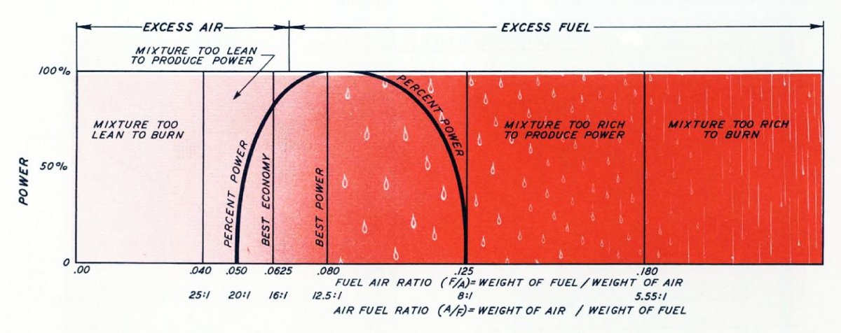
Figure 1 shows the "percent of power curve" for various fuel–air ratios, with notations indicating the ratio making best power, the ratio making best economy, and the ratios where the mixture becomes unburnable.
|
| Fig. 1. Fuel–Air Ratios versus Economy and Power. Note that fuel–air ratios of 0.040 (25:1 A/F) and lower are too lean to burn and that fuel–airratios of 0.180 (5.5:1 A/F) and above are too rich to burn. Also note that the percent power curve drops to zero at both the left side at 0.050 (20:1 A/F) and right side 0.125 (8:1 A/F), best economy is at 0.0625 (16:1 A/F) and best power is at 0.080 (12.5:1 A/F). |
Fuel–air ratios are a decimal number of less than one and are the percent of fuel in a given volume of air. Air–fuel ratios are a number of pounds of air to one pound of fuel. Both expressions are equivalent, and represent the same proportions of air to fuel. One pound of air at sea level is approximately 13.072 ft3, roughly the size of a 2 ft-4 in cube. At 18,000ft, air weighs only half as much per cubic foot of what it weighed as sea level, resulting in one pound of air being close to 26.144 ft3. At 34,000 ft, air weighs only half as much per cubic foot of what it weighed at 18,000ft, and at that altitude, one pound of air occupies about 52.288 ft3.[22]
Hydrocarbon fuels, such as aviation gasoline, have a range of fuel–air ratios that can burn in an engine. There is only one fuel–air ratio that produces no excess hydrocarbons or oxygen after combustion is finished. That mixture is the stoichiometric point. That mixture, while chemically the best, does not produce the most poweror the best economy. Nor is it the best ratio for engines operating at higher horsepower levels, as a richer mixture prevents detonation. Detonation is an explosive force caused by the autoignition of the gasses in the combustion chamber. The chemicals that form gasoline are presented later in this work.
Decades of Discovery
In the second Annual Report NACA of 1916 as Technical Report No. 11 Carburetor Design - A Preliminary Study of the State of the Art by Charles E. Lucke, Professor of Engineering at Columbia University, New York City, found that there were more than 3,400 carburetor patents on file, some as early as 1875. After examination, the examiner placed the carburetor design into one of a number of classes and subclasses.[23] A carburetor should supply the engine with a suitable mixture of fuel and air. Technical Report No. 11 described a suitable mixture that gave maximum power for all engines. It also provided the engine designer with a basis for estimating how much greater piston displacement an engine operating with maximum economy mixture (95%) should have than one operating with a maximum power mixture (100%) for both developing the same horsepower.[24] Technical Report No. 11 classified carburetors that did not have a way to determine the volume of air flowing through the engine’s air intake system as evaporative carburetors. These carburetors simply used the fuel that evaporated into the air as the method of mixing the air and fuel. In this carburetor, the fuel and air are in direct contact as the air flows through or across the fuel within the carburetor. The theory of operation is that as fuel changes from a liquid, it vaporizes and is absorbed into the air until the air cannot absorb any more. The temperature and vapor pressure of the fuel determine the amount of vaporization. Low vapor pressure, heat and agitation will all increase vaporization of a liquid. This fuel-air mixture is not the ideal mixture, and it varies from too lean to too rich. When the mixture is in the combustible range, the engine runs, at least to some degree.
The fuel vapor is absorbed into the air as it passed over or bubbles up through the liquid fuel, up to the saturation limit of the air. This method was satisfactory when the engine operated at a steady speed and load, but otherwise, it was not very reliable. Carburetors using this process are evaporative carburetors.[25] Stationary farm or industrial engines in the late 19th century and early 20thcentury used evaporative carburetors. The village gas works used this type of carburetor to produce the mixture for the gas street lamps and lighting in private homes. The electric lamp caused the lighting-gas industry to expire.
 |
 |
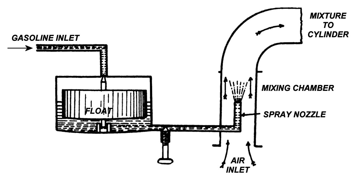
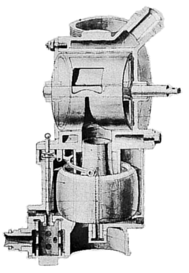
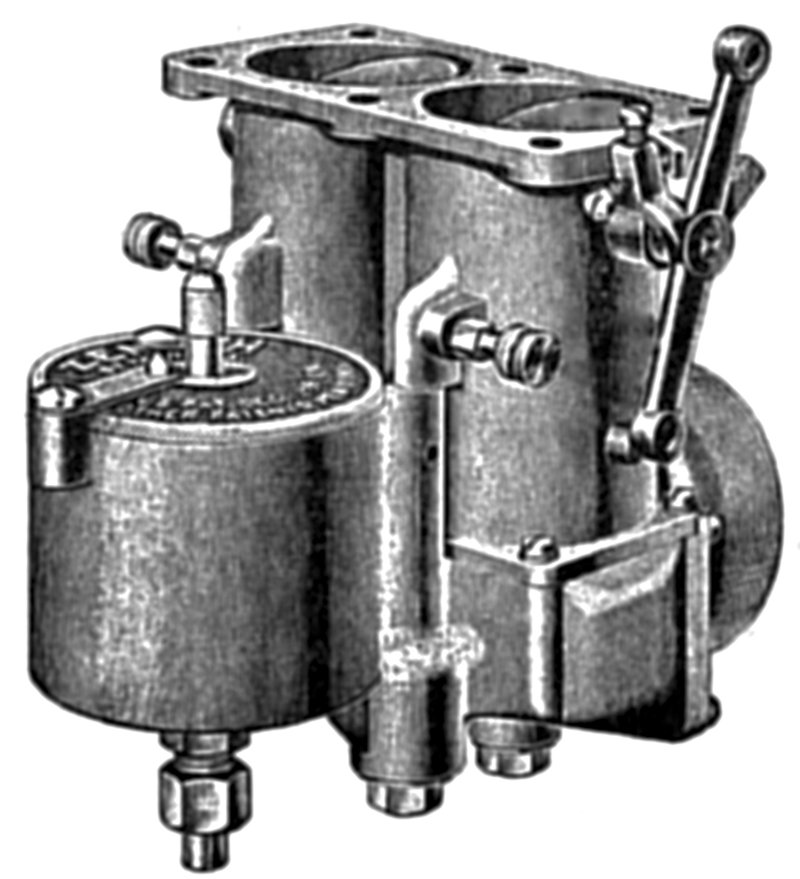
| Fig. 2. Simple Float Carburetor with Manually Adjustable Jet | Fig. 3. Example of a Floatless Carburetor Used on a Rotary Engine |
This carburetor feeds a rotary-type engine through its fixed hollow crankshaft. Another method of mixing the fuel and air is a float chamber with an inlet valve that supplies fuel through a manually operated needle valve. The valve, located within the pipe that supplies air to the engine, controls the amount of fuel flowing to the discharge nozzle. Note that the volume of air moving through the carburetor is not measured. It is up to the engine operator to set the fuel flow as the load on the engine changes. This type of carburetor is best suited for a stationary power unit with a reasonably constant load, allowing a fuel setting that produces the correct mixture for a long period before a mixture adjustment is necessary.
Technical Report No. 11 classified carburetors that measure the volume of the air flowing into the engine and use that data to control the fuel–air ratio as proportioning carburetors.[26] This type of carburetor is much better at mixing the correct fuel charge than the evaporative type, and is the type of carburetor found on most aircraft engines. For it to properly function, the engine requires exactly the right proportions of gasoline and air. A perfectly balanced mixture results in the highest engine efficiency. Greater exertion of the engine will call for more air and fuel, balanced in the same proportions, in order to produce the best results.
Once the fuel and air are thoroughly mixed, the engine’s cylinders take in air and fuel, turning it into energy. The device that performs this function is the carburetor. A simple carburetor has a fuel chamber, an air entrance and a jet. Suction created by the pumping of the pistons draws the fuel and air through the carburetor and into the engine. Each downward suction stroke draws a fresh charge of mixed fuel and air from the carburetor into each cylinder, where it is compressed and then ignited.
The simple carburetor does not work well at high engine speed, as fuel is more responsive to suction than is air. As the engine gains speed, the flow of fuel into the engine increases faster than the flow of air, and the resulting mixture becomes too rich at high engine speed. It is no longer the perfectly balanced mixture needed in order to produce a high power output.
More speed should be a matter of a larger mixture supply, not a change in mixture richness. There were many attempts to overcome this natural tendency of the mixture. However, due to mechanical difficulties or sensitiveness to changeable atmospheric and temperature conditions many of these devices have proven unsatisfactory.
The first two proportioning carburetors, described below, were British inventions.
Claudel-Hobson Carburetor
The Claudel-Hobson carburetor is the father of all float-type carburetors, as almost all other float-type carburetors contain so many of its design features. Other types of carburetors are simple to understand, once a technician understands the design and operation principles of the Claudel-Hobson carburetor.[27] The most outstanding features of the Claudel-Hobson carburetor are the position of the jet and the design of the throttle. In previous types of carburetors, fuel drawn from the jet or nozzle was not atomizing or mixing with the air as it left the jet. The Claudel carburetors offered two patterns of spray jet/nozzles, described below. The early Claudel carburetors, were the R.A.F. model, and have an "air injector" type of jet/nozzle. Later Claudel models were either the Z or the HC types, and have a "diffuser" type of jet/nozzle mounted above the jet, located at the foot of the spray chamber. Both the "air injector" and "diffuser" atomize the fuel, mixing it with air before it enters the main air stream drawn from the air intake duct or port. When the main air stream passes by the delivery nozzle in the spray chamber, it receives a fine, mist-like vapor of richly carbureted air.[28] The fuel is already broken up into a vapor and easily combines with the main airflow. The discharge nozzle has a number of holes drilled around the sides where the vapor discharges into the passing airflow. Both patterns of jets automatically adjust the proportions of air and fuel in the mixture to match the needs of the engine.[29]
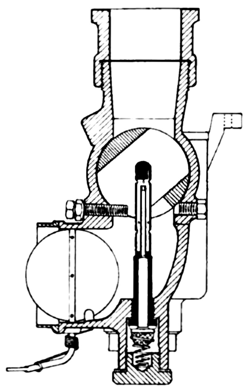 |
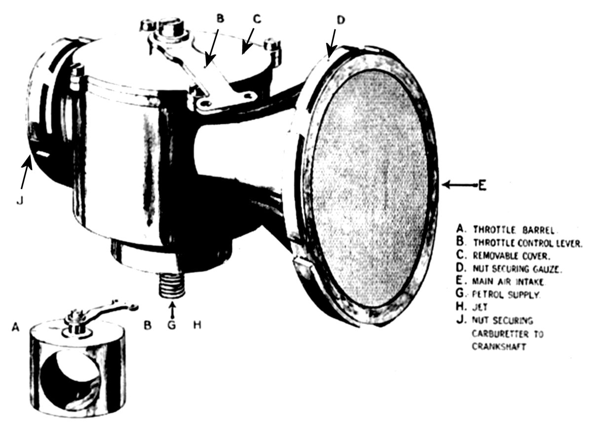
| Fig. 4. Claudel-Hobson Model R.A.F. Carburetor. The throttle is located within a rotating barrel, combing a graduated control of the air-fuel mixture with a "nearly frictionless" air passage when at full throttle. |
For engines running at a very low idle speed, a Claudel-Hobson motorcar type of throttle and barrel is used. The modified throttle haa a clover leaf-shaped slot cut into the lower portion of the throttle barrel. In the air injector models, this slot is narrower and longer than in the diffuser models. When the throttle is closed, the delivery nozzle protrudes into the interior of the throttle barrel through the cloverleaf slot. The slot then acts as an air regulator, where the reduced airflow is concentrated around the delivery nozzle, with an increase in its velocity.[30] Note that the R.A.F. carburetor has a spring loaded choke mechanism to assist starting. The spring returns the choke to the open position once the engine starts.
An external adjustable screw protrudes into the cloverleaf slot to provide a very fine adjustment of the air supply. This screw is the primary mixture adjustment. On some models of the carburetor, the idle mixture enters the induction pipe through a bypass passage; the size of this bypass is set with a second external screw. On other models, which were used on engines that are less sensitive to the fuel–air mixture at idle, no bypass passage is provided, and the idle mixture is fed directly into the induction pipe through a small opening when the throttle lever is in the idle position tight against the stop screws.[31]
Beardmore Carburetor
The Beardmore is a float type carburetor, and has two main parts – the float chamber and the throttle housing, sometimes referred to as the mixing chamber. The throttle housing mounts on top of the float chamber, immediately above the jets and venturi tube.[32] This, like most early carburetors, is an updraft carburetor. Note that in the Beardmore design, like that of the Claudel-Hobson carburetor, the throttle chamber surrounds the cylindrical throttle barrel, which turns on its horizontal axis. The housing has a water jacket and a number of openings to the choke tube, jet, main air intake, extra air intake and the induction manifold. The position of the throttle barrel sets the effective area of the opening, which has three specially shaped openings that correspond with the housing openings. [33] Note that the British term choke tube is the same as the American term venturi tube.
 |
| Fig. 5. The Beardmore Carburetor |
The Beardmore carburetor has one particular advantage over the others of its time, that being that it continued working when flying at angles up to 45°, maintaining a constant fuel level in the float chamber, due to the uniquedesign of the float chamber.[34]
The jet and choke tube are surrounded by the float chamber which contains an annular shaped copper float. The needle valve, actuated by a spur shaped lever at the side of the float chamber, resting on a small rim at the top of the float. The needle valve feeds gasoline through a small filter at the base of the carburetor. Placing the jet at the center of the float chamber insures that if tilted, the jet orifice has a constant gasoline supply, even when the carburetor is at a steep angle.[35]
The throttle barrel has three apertures on its circumference, one for the admission of air and fuel into the barrel, which has to act as a mixing chamber for the carburetor, one for the admission of extra air, and the remaining one for the admission of the mixture into the induction pipe to the engine. A choke tube intensifies the suction at the mouth ofthe jet. This extra air intake opens only after the engine has reached a certain speed, thereby increasing the efficiency of the engine by reducing the richness of the mixture at high engine speeds.[36][37]
Zenith Carburetor
The French scientist M. Baverey, the inventor of the Zenith carburetor, solved the problem of a richer fuel–air mixture when passing through the carburetor at high velocity. His carburetor arranging the fuel jets in accordance with the physical law that govern suction, resulting in a design with an accurately proportioned fuel–air mixture. He used natural methods, not mechanical methods to obtain the mixture’s precision.
 |
 |
| Fig. 6. The Liberty Engine’s Zenith Carburetor | Fig. 7. Zenith Carburetor in Cross Section |
To overcome the variation of the simple jet, which allows the mixture to grow richer under increasing suction, Baverey introduced the compensating jet, which has exactly the opposite effect of a typical jet, allowing the mixture to grow leaner under increasing suction. He then combined the two jets, inventing the compound nozzle, and achieved the desired result, a carburetor that delivers a mixture containing exactly the right proportions of air and fuel at all engine speeds.[38]
Liberty and the Hispano-Suiza engines built in the United States during World War I used the Zenith carburetor. After the war, the market for new aircraft carburetors was almost zero, as 10,000 (if not more) new Liberty engines with Zenith carburetors were available as after-war surplus.[39] This offered little incentive for further carburetor development, and the Zenith Carburetor Company eventually left the aircraft carburetor field to its competitors by default.
The Bureau of Standards tested a Liberty V-12 engine equipped with the standard Zenith carburetor to set a base line for future engine tests. The engine testing included operation at various throttle settings, loads and altitudes. The results, titled Technical Report No. 102, Performance of a Liberty 12 Engine written by S.W. Sparrow and H.S. White, published by NACA in the sixth Annual Report of 1920, reported that at altitudes above 15,000ft, the Zenith carburetor was unable to produce a suitable mixture.[40]
Stromberg Carburetor
Zenith’s competitor in the aircraft carburetor business was the Stromberg Motor Devices Company, a manufacturer of American automobile carburetors, a company that had not made aircraft carburetors until the end of the war. Stromberg made its first attempt at aircraft carburetor construction, with most of its costs paid for by the Army and Navy. The Stromberg carburetor had a patented air bleed that broke up the fuel emerging from the nozzle into very small droplets, thereby improving fuel vaporization appreciably. The Stromberg aircraft carburetor using this air bleed was in production between 1922 and 1923.[41]
 |
| Fig. 8. The Stromberg Carburetor |
The Stromberg and Zenith carburetors were very much like the contemporary automobile carburetor. As in an automobile engines, it was necessary to maintain a constant ratio between the fuel and airflow in an airplane engine. To do this, a valve controlled by a float within the fuel bowl admitted fuel, keeping a constant, albeit low, fuel pressure at the jet. Fuel passing through the jet flowed through a passageway to a discharge nozzle, located within the venturi. The suction in the venturi’s narrowest point lowers the pressure at the outlet ports of the discharge nozzle, passing the suction through into the fuel passageway and on to the discharge side of the metering jet. The pressure drop as the fuel flows through the jet is similar to the pressure drop in air as it flows through the venturi.[42] The original Stromberg aircraft carburetor was unable to produce a constant ratio of fuel and air under varying load, even when the engine was stationary on the ground. Development continued until a design that had a reasonably straight-line mixture characteristic. Later, additional refinements, such as adding an accelerator circuit, provided the extra fuel needed for sudden acceleration.[43]
There were other changes needed to correct the special problems encountered only in flight. Early aircraft performed poorly in a climb or dive as the carburetor float was located either before or behind the discharge nozzles, causing the mixture to become too rich or too lean when the airplane was nose up or down. Stromberg corrected this by changing the location of the float to the side, or by using twin floats, one ahead of the venturi and one behind.[44] Problems also existed when flying inverted or when attempting an aggressive maneuver that caused "negative g" forces on the aircraft. These conditions made the fuel rise to the top of the float bowl instead of staying on the bottom where it was located when in normal flight. Then air (rather than fuel) entered the carburetor jets. It was some years before finding a solution that supplied a limited fuel flow to the engine under these adverse conditions. The eventual inverted fuel supply usually allowed the engine to continue running.[45]
By the end of the 1920s, improvements made to the Stromberg float-type carburetor resulted in a satisfactory fuel-metering device, suitable for most flying conditions. In normal flight, it provided the correct fuel and air mixture through all engine speeds and loads. This mixture, while not perfect in inverted flight or under negative g conditions, worked for civil aircraft, as they seldom operate in such radical circumstances or situations.[46] The Stromberg carburetor did not have an automatic adjustment for the variation in air density caused by changes in temperature or altitude. Zenith had produced a carburetor with an automatic compensation device about 1918 and Stromberg had made an experimental model with a similar device. The Army bought some of the Stromberg models for service test sometime in 1923, but there were no other sales. In 1928, Stromberg, working under an Army contract, produced a number of add-on type external automatic mixture controls that worked reasonably well. They were difficult to install, and again, the device was no longer under consideration.[47] It was not until 1934, that there was a real need for automatic altitude compensation, as the ceiling of airplanes of the time was quite low, seldom exceeding 10,000 ft. The pilot could tell by the loss of engine speed and powers that the mixture was incorrect, and could then manually adjust it. For this reason, the Army did not believe that it was worth the trouble to install the automatic device on its service airplanes, and none were purchased. The Army had very limited experimental funds, and that fact did not allow any funds for the development of a more refined altitude compensator, particularly one built into the carburetor.[48] Stromberg was unwilling to do any further development at its own expense, as sufficient sales to make it profitable just did not exist. In the 1920s, the price of a new carburetor was quite high, so high that Curtiss considered making its own carburetors to save money. Automatic mixture control was just not worth what it would cost for its development and testing.[49]
In 1934, the situation suddenly changed with the introduction of constant-speed propellers. The pilot could not quickly correct the mixture for the loss of power due to an incorrect fuel mixture, thus, an automatic mixture control became an essential part of the carburetor.[50] In 1935, the Army installed some of the external controls originally purchased in 1928 on a number of Army Boeing P-26s. Suddenly, the development of an integral automatic mixture control became a priority. Although the Army paid Stromberg for its work under an Army contract, much of the development done on engines in the Wright and Pratt & Whitney engine plants, with the tests paid for by the engine companies. A carburetor with a built-in automatic mixture control was available as standard equipment on production engines by 1936.[51] The automatic mixture control is typical of the improvements possible by adding refinements to the original float-type carburetor designs. It was said that no need for a refinement was ignored in the first 15 years after the end of the war, but if one of the services had the funds, and if the cost of the production article did not matter, then these refinements would come along much sooner.
There was one very serious problem from the very beginning of the float-type carburetor development, and by 1930, for the military, additional, more serious problems appeared.[52] The primary problem was ice forming in the carburetor. It was essential for the operation of a float-type carburetor that the throttle be located after the air had passed through the venturi. The fuel nozzle is located within the venturi, spraying fuel into the passing air. A portion of the fuel flowing from the nozzle quickly evaporates, becoming colder as the heat of vaporization leaves the liquid. The fuel–air mixture then strikes the throttle, cooling it, often to a temperature below the freezing point of water. If low temperature and high humidity were extant, the air condenses to a cold liquid in the low pressure, immediately freezing on contact with the throttle. The ice that formed on the throttle blocked the airflow, and if it became excessive, it soon froze the throttle tightly in the open position.[53] Methods of preventing this type of icing using the readily available exhaust heat were developed. Venting heat into the intake airflow before it entered the carburetor or by heating the carburetor with circulating oil to remove or prevent the formation of ice. The heated air resulted in a loss of engine power due to the lower the air density of the hot air, and that could be very serious. This hot air system worked poorly if at all when the engine was at low power while gliding to a lower altitude, a time when ice could easily develop, if icing conditions were present.[54]
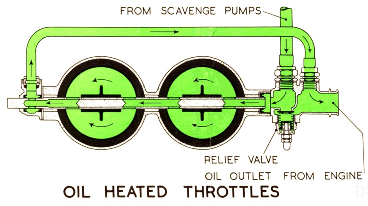 |
| Fig. 9. Oil Heated Throttle Used on a Rolls-Royce Merlin SU Carburetor |
The second problem was that the float was really an unsuitable device for use in an airplane. These two problems became critical due to the start of the new dive-bomb method used by the Navy, a tactic which was also just being tried by the Army. Inverted flight and some other maneuvers were possible without killing the engine, at least whith an inverted flight restriction installed in the float chamber, a remedy that completely failed when the airplane was briskly nosed over into an abrupt dive. When the pilot needs to quickly enter a dive, the fuel and air in the float chamber changed places so rapidly that they mixed together, resulting in emulsion of fuel and air. The fuel charge that entered the cylinders was then too lean to burn, slowing or stopping the engine.[55] More important than the pushover problem was that when dive-bombing at a steep nose-down angle that the float could not maintained the correct fuel level in the fuel bowl due to the fore-and-aft floats that had evolved in the 1920s. The result was that in the steep dive, the mixture soon became over-rich and the exhaust gases were still burning while leaving the engine exhaust system, even to the point that on some occasions, it set fire to the fabric-covered airplane. A makeshift solution that included a check valve set an arbitrary fuel flow limit solved that problem. Although this eliminated the fire, the valve did not supply the engine with a correctly metered fuel supply.[56]
Before the end of the 1920s, both the Navy and the Army were very anxious to obtain a fuel-metering device with the troubles associated with the conventional throttle and float designs. Both services used as much of their experimental funds that they could spare to encourage development in the advancement of such devices. For a number of years, the Army believed that a basic improvement was more likely found by using a fuel injection system rather than with a new type of carburetor, and had expended the larger amount of its available money, even after the first acceptable results were obtained from the new types of carburetors that were then under development. [57]
In the late 1920s, the first attempt to develop a new type of aircraft carburetor in the United States began at Stromberg, at the Navy's initiative. A number of new designs were tested, but the Navy did not see Stromberg's attempts to improve its standard float-type carburetor as very successful. Zenith was no competition to Stromberg, as by then it had exited the aircraft market,and was no longer building aircraft carburetors.[58]
Steel Products Engineering Corporation Carburetor
The Steel Products Engineering Corporation (SPE) made a first attempt at designing a floatless carburetor. Although they held several Navy contracts in other fields, SPE had no carburetor design experience whatsoever. At the Navy's expense, SPE worked for several years on a floatless carburetor.
Incredible as it may seem, this carburetor was nothing more than an ordinary float-type carburetor with the float removed, and nothing put in itsplace! With an uncontrolled fuel flow, disaster was eminent, with excessive amounts of fuel pouring into the engine cylinders, causing severe engine damage.
The Wright Field engineers refused to have anything to do with it, as it was obviously an unworkable design. In1931, SPE persuaded a few top Navy officers in Washington DC to order Wright Field to purchase some of their experimental carburetor models. Wright Field engineers were then forced to test a carburetor that they knew would not work without a float, or another way of controlling fuel flow, as the engine would flood, resulting in damage ordestruction of the engine. The tests that run in 1932 proved that the design was unsound. After the tests, both the Army and the Navy dropped the carburetor design from any further consideration.[59]
Endnotes
[6] Aero Engines, Magnetos and Carburetors, p 46.
[7] NACA Technical Report No. 11, pp 58-59.
[8] Aero Engines, Magnetos and Carburetors, pp 43-44.
[9] NACA Technical Report No. 11, p 59.
[10] Aero Engines, Magnetos and Carburetors, p 43.
[11] Aero Engines, Magnetos and Carburetors, pp 45-46.
[12] NACA Technical Report No. 11, p 58.
[13] Aero Engines, Magnetos and Carburetors, p 58.
[14] Investigation Report 200002157, pp 33-38.
[15] Investigation Report 200002157, pp 33-38.
[16] Investigation Report 200002157, pp 33-38.
[17] Investigation Report 200002157, pp 33-38.
[18] Bosch Fuel Injection Systems,ch 2.
[19] Investigation Report 200002157, pp 33-38.
[20] NACA Technical Report No. 48, p 590.
[21] NACA Technical Report No. 189, p 109.
[22] Aircraft Carburetion, p 90.
[23] NACA Technical Report No. 11, p 62.
[24] NACA Technical Report No. 189, p 109.
[25] NACA Technical Report No. 11, p 58.
[26] NACA Technical Report No. 11, p 58.
[27] Aero Engines, Magnetos and Carburetors, p 52.
[28] Aero Engines, Magnetos and Carburetors, p 52.
[29] Aero Engines, Magnetos and Carburetors, p 52.
[30] Aero Engines, Magnetos and Carburetors, p 52.
[31] The Claudel-Hobson Carburettor, pp 5-6.
[32] Aero Engines, Magnetos and Carburetors, pp 54-57.
[33] Aero Engines, Magnetos and Carburetors, pp 54-57.
[34] Aero Engines, Magnetos and Carburetors, pp 54-57.
[35] Aero Engines, Magnetos and Carburetors, pp 54-57.
[36] Textbook of Aero Engines, p 183.
[37] Aero Engines, Magnetos and Carburetors, pp 54-57.
[38] Dyke's Automobile and Gasoline Engine Encyclopedia, pp 1292-1299.
[39] The Liberty Engine, p 105.
[40] NACA Technical Report No. 102, p 561.
[41] Development of Aircraft Engines, p 512.
[42] Development of Aircraft Engines, p 512.
[43] Development of Aircraft Engines, p 512.
[44] Development of Aircraft Engines, pp 512-13.
[45] Development of Aircraft Engines, p 513.
[46] Development of Aircraft Engines, p 513.
[47] Development of Aircraft Engines, p 513.
[48] Development of Aircraft Engines, p 513.
[49].Development of Aircraft Engines, p 513.
[50] Development of Aircraft Engines, p 513.
[51] Development of Aircraft Engines, p 513.
[52] Development of Aircraft Engines, p 513.
[53] Development of Aircraft Engines, p 513.
[54] Development of Aircraft Engines, pp 514-516.
[55] Development of Aircraft Engines, pp 514-516.
[56] Development of Aircraft Engines, pp 514-516.
[57] Development of Aircraft Engines, pp 514-516.
[58] Development of Aircraft Engines, pp 514-516.
[59] Development of Aircraft Engines, pp 514-516.
Send mail to
![]() with questions or comments about this web site.
with questions or comments about this web site.
![]()