A Brief History of Aircraft Carburetors and Fuel Systems
Part 7: Floatless Carburetors — Chandler Groves, Holley and Chandler Evans
by Terry Welshans
Bardstown, Kentucky
for the Aircraft Engine Historical Society
August 2013
Table of Contents
A carburetor must first reduce and control the flow of fuel entering the device. A float-operated fuel inlet valve allows pressurized fuel to enter the carburetor fuel bowl, vents to the atmosphere, thereby reducing the fuel pressure to nearly zero in comparison to atmospheric pressure.[148] Float type carburetors work best when in a stable operating condition. General aviation aircraft operate in a range of conditions not much different from that of an automobile, so a float type carburetor works well. Large or fast aircraft are a different matter, especially when considering that propeller-driven fighter aircraft of World War II may fly inverted, or through a series of high g turns, climbs and dives, all at a wide range of speeds and altitudes,and in a very short time.
There are a number of methods of eliminating the carburetor float. The first method designed by Steel Products Engineering Corporation in 1931 was a failure, as nothing controlled the inlet fuel pressure after the float was removed. The Chandler Groves and the Holley floatless carburetor are similar to a float-type carburetor in that there is a reduction of fuel pressure from supply pressure to atmospheric pressure. Like a float-type carburetor, venturi and intake manifold suction pulls fuel into the airstream. The fuel delivery nozzle is located at the narrowest part of the venturi.
A pressure carburetor is a floatless carburetor that does not rely on engine intake manifold suction to pull the fuel into and mix with the air drawn into the engine. In a pressure carburetor, fuel within the carburetor, from entry to spray nozzle, is above atmospheric pressure. Pressure carburetors, also known as injection carburetors, inject fuel into the airflow.The pressurized fuel has a secondary benefit in that the fuel atomizes into smaller droplets that evaporate better than the larger fuel droplets found with float carburetors. Lastly, the fuel can enter the airflow at any point beyond the carburetor, as a pressurized spray does not require a low pressure area to pull it into the airstream, as in the venturi of a float carburetor. Smooth operation and economy are the result from atomizing fuel under pressure.
There are two primary designs of injection carburetors, each with a distinctively different design philosophy and accompanying patents. Pressure carburetors utilize a pump to deliver fuel under pressure to a nozzle located at the entrance of the internal supercharger. Since the system is entirely closed, it will operate normally during all types of maneuvers. The fuel is correctly metered at all operating loads and altitudes. Fuel injection systems are also included in the floatless carburetor group. There are two types of fuel injection control systems. The first senses the mass of air entering the engine with a master control portion that operates much like a pressure carburetor. The master control unit sends control pressures to the fuel injection metering system. The metered fuel supplies the injection pumps. The injection pumps divide the fuel into equal parts, sending the fuel to one or more injection nozzles that spray the fuel into the air intake system, intake valve port or directly into the cylinder head. The second type, called a speed-density system, uses a pump that senses engine speed, and under the control of the mass airflow sensors, pressurizes and distributes fuel directly into the cylinder head.
Chandler Groves Floatless Carburetor
After Milton Chandler left Bendix, he and Milton J. Kittler developed a floatless carburetor that interested the Holley Carburetor Company. The original patent 2,088,464 granted July 27, 1937. Chandler was able to get financing for a startup company based on this patent. This patent is an improvement of the 1938 patent.
Design and Development
The new Chandler-Groves carburetor differed from the basic Stromberg design in two essential respects. The first was the use of a completely different, although already known, type of throttle. Instead of a butterfly valve located in the air stream after a fixed venturi, Chandler used a venturi whose cross-section was variable so that it could itself serve as the throttle.[149] This meant that no fuel was sprayed on the throttle, which accordingly was not so likely to freeze up in icing conditions as the Stromberg throttle. It also simplified production enormously; the new type of throttle made it possible to construct the carburetor by bolting together a number of castings each of which was exceedingly simple and easy to produce.
The second characteristic feature of the design was the means by which fuel is delivered to the jet at a constant rate. The valve controlling the entrance of fuel to the chamber feeding the jet reacts, and the pressure within the chamber was kept constant, not by the level of the fuel acting on a float, but directly by the pressure of the fuel acting on a diaphragm linked to the valve. This change eliminates the difficulties inherent in a float in a typical aircraft carburetor; Chandler's primary motive, however, was simply a desire for novelty, or a "selling point" to use in competition with Stromberg. The float was satisfactory in most types of flight, while the market for engines for fighters and especially in dive-bombers, where the float performed really badly, was only a small fraction of the total market.
The original development of the new carburetor received very few resources. Prototypes were ready for test early in 1935, but Chandler-Groves had neither facilities for running the carburetor on an actual engine nor even an "air box" large enough to test a carburetor of this size. Wright Field made the first air-box tests, and Wright Aeronautical Corporation made the first runs on an actual engine at its plant. Although Wright and the services were eager from the beginning to have competition created in the carburetor industry, no one was very enthusiastic over the design of the Chandler-Groves carburetor.
Late in 1935, Navy flight-testing of the new carburetor demonstrated that it was very much less subject to icing due to evaporation of fuels than the Stromberg carburetor. The Cyclone lost a great deal of power when the intake switched from cold air to the 150°F air that was required to eliminate ice once formation had started. Both Wright and the Navy became very much interested and gave wholehearted support to further development of the Chandler-Groves carburetor. Lacking the necessary facilities in his own plant, Chandler himself participated in the very extensive running of the carburetor on actual engines at the Wright plant at Wright's expense and in that done on the refrigerated air box at the Naval Aircraft Factory at the Navy's expense.[150]
The new carburetor tests used the Navy's air box, which could simulate performance at altitude since it supplied air at the proper temperature as well as the proper pressure. While under test, the aneroid mixture control was unsatisfactory and the test continued with it disconnected. This running test led to the observation that automatic mixture control or altitude compensation appeared to be inherent in the basic carburetor itself, although the reason was unknown. The special mixture control now seemed to be unnecessary.
Due to t he great deal of assistance contributed to the development of the Chandler-Groves carburetor in the form of experimental running by Wright and by the Navy, Chandler's company had to invest $100,000 in development costs in order to avoid loss of rights in the design. The carburetor entered into production in the first half of 1937.
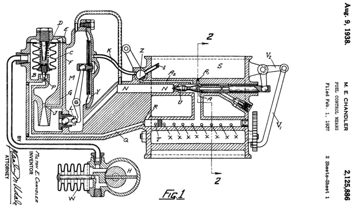
The Chandler-Groves carburetor is a variable venturi carburetor with fuel flow controlled by a mechanically operated throttle. A fuel pressure regulator maintains a constant pressure as the fuel flow varies. A fuel flow venturi controls the power enrichment valve, admitting extra fuel as determined by the lower pressure in the control venturi. The mixture control uses an air bleed to offset the fuel pressure in the fuel control.
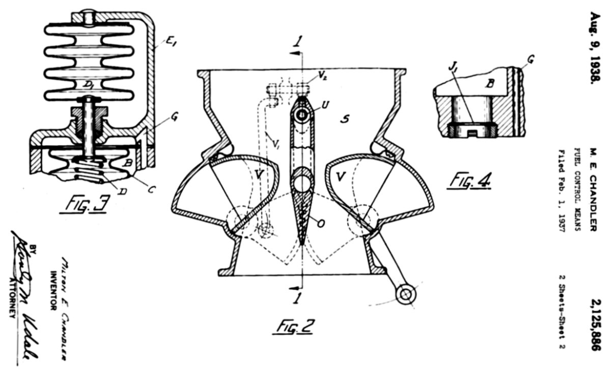
Figure 50 is a cross section of the throttle body, shown as a side view. The variable venturi is in the center. The gearing that synchronizes the two moveable venturi plates connects to the fuel-metering valve through linkage V1 and V2. The fuel metering diaphragm valve and enrichment valve are to the left. The pilot's throttle lever connects to the lever shown at the lower right of the throttle body. Two variable-venturi sections "V" are controlled by the pilot's throttle control lever through the appropriate linkage connecting to linkages V1 and V2 to move the fuel control "U" to regulate the amount of fuel admitted to the fuel discharge spray bar through spray nozzles "X", as shown in sheet 1.
The venturi sections nearly touch the fuel spray bar when in the idle position. As the throttle opens, the venturi widens until, at full throttle, they are in the position shown by the dotted lines. In the idle or engine stopped position, the venturi closes until they almost touch the center divider. The purpose of a variable venturi is to keep a constant velocity of air flowing through the carburetor. This constant velocity is very helpful at low engine speed as the air velocity is greatest at the fuel discharge nozzle, enhancing the atomization and vaporization of the fuel.
|
|
| Fig. 50. M.E. Chandler's Patent for the Chandler Groves Floatless Carburetor, Sheet 1. | Fig. 51. M.E. Chandler's Patent for the Chandler Groves Floatless Carburetor, Sheet 2. Throttle Body End View Cross Section. |
The Chandler-Groves carburetor was standard on all Navy Cyclones of the new G-100 model put in production about this time. The airlines became interested in the new carburetor almost as soon as they heard of its performance as reported by the Navy and Wright. They were attracted both by the relative freedom from icing,which had been the feature that originally, aroused the interest of the Navy and Wright, and by the low price, which had been the guiding principle of the original design. TWA ran a Chandler-Groves carburetor in regular service by March 1937, and it became standard on new airline Cyclones of the G-100 model as well as on the Navy engines.
It was later, when undergoing additional testing, that with the altitude mixture control removed, there was no appreciable change in operation. Further testing found that the lower pressures found at high altitudes had caused the fuel in the system to vaporize, raising the internal fuel pressure in such a way that it compensated for the altitude. A report of test results reached the US Navy, who then dropped the Chandler Groves carburetor from further consideration. The US Army had no interest in this carburetor at all. With sales dropping to zero, Chandler Groves Carburetor Company ceased to exist. Milton Chandler moved on to form the Chandler Evans Company.[151]
Once the Chandler Groves Company dissolved, Holley Carburetor Company, the major investor, took over the design and assets of the company. Holley assigned several engineers to this project, hoping that they could resuscitate it into a workable design.
The Holley brothers had a large stake in the Chandler Groves Company, and when that company folded, the Holley brothers became the full owner of the Chandler Groves design.[152] The Holley floatless carburetor resulted from a number of modifications made to the Chandler Groves carburetor design by Holley's engineers. Although this carburetor is floatless, it is not a pressure carburetor, as the fuel delivery is similar to that found in a float-type carburetors, in that the fuel pressure at the regulator valve essentially drops to atmospheric pressure. The low pressure in the venturi draws fuel into the airflow, a design similar to that of the float-type carburetor. The fuel-metering valve does not regulate pressure; instead, it adjusts the size of the metering jet as the throttle moves. This design can operate inverted while maintaining the correct fuel-air mixture to the engine.
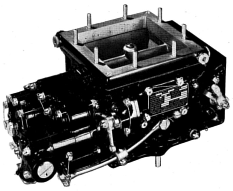 |
| Fig. 52. Holley 1375F Variable Venturi Carburetor |
The Holley floatless carburetor was a variable-venturi type carburetor. The vacuum drawn by the venturi passes through a series of holes in the parts of the venturi that faced the fuel delivery bar located between the two geared-together venturi pieces. At idle, the venturi and fuel delivery bar are almost in contact with one another. With the throttle closed, the maximum clearance between these three parts is about the diameter of a human hair - 0.003".
There are four Holley floatless carburetors sizes. The model 700 is a small updraft carburetor of 7 in² throttle opening and is used on inline engines of up to 600 hp, including the 4 and 6-cylinder models made by Menasco. The model 1375 is a medium-size downdraft carburetor of 13.75 in² throttle opening designed for the Pratt & Whitney R-1830 engine used on Consolidated B-24 bombers. The model 1685 is a medium-size downdraft carburetor of 16.85 in² throttle opening designed for the Wright R-2600 engine used on the North American B-25 bombers. The model 2795 is a large downdraft carburetor of 27.95 in² throttle opening, designed for the Wright R-3350 engine used on the Boeing B-29 bombers. The US Army dropped this model in favor of the CECO model 58CPB-4 hydro-metering carburetor.
Holley Models 1375F and 1685F Carburetors
Description
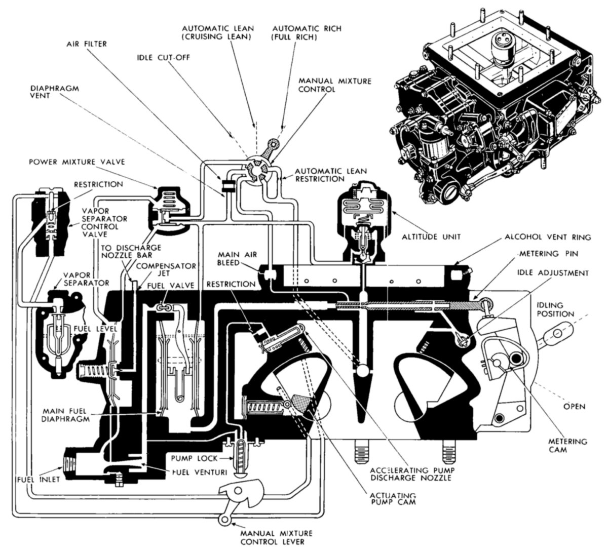
The Holley aircraft engine carburetor has a single air passage into which fuel is supplied from a single fuel supply chamber, inducing the fuel into the air passage the same as carburetors of older design; that is, a controlled pressure differential that is produced by a the reduction in the cross-sectional area of the air passage opening. This type of carburetor differs from a float-type carburetor in that a diaphragm mechanism replaced the float-mechanism, and the air passage has a variable venturi rather than the conventional butterfly valve and fixed venturi. The fuel discharge nozzle and venturi throttles are inherently free of ordinary icing troubles. The type of fuel metering system and throttle used in this carburetor provides partial compensation for changes in altitude. In order to obtain more exact altitude adjustment and for increased economy under favorable operating conditions, a manual control is provided for leaning the fuel-air ratio. The side of the carburetor on which the data plate and the throttle and mixture control levers are located is the "rear" side. The "right" and "left" sides of the carburetor are as when looking from the rear toward the front.
Main Body
The main body of the carburetor consists of two end blocks bolted between two side plates. The main body consists of a number of simple castings, two throttles and throttle shafts, metering channel and discharge nozzle. The throttles are modified cylindrical sectors with the discharge nozzle between them, forming a streamlined venturi shaped passage for all throttle settings. The throttles fit in the main body with a small end clearance, and leather brushes that bear lightly on the top of the cylindrical surface. A synchronizing gear on each throttle and on the throttle lever shaft drives them in unison.
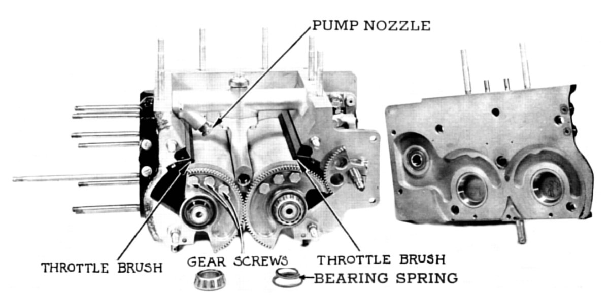 |
| Fig. 53. Holley 1375F Carburetor Body with End Removed, Showing Throttles. Roller bearings support the throttles and ball bearings support the throttle shaft. |
The main diaphragm mechanism attached to the left side of the carburetor by nine studs, and can be removed and replaced without disturbing the other parts of the carburetor. The mixture control valve is self-contained in a small casting fastened to the rear of the carburetor, and is removed as one piece. The carburetor is vented through a hollow rectangular casting above the air entrance, and has a number of small holes around the inside surface. This vent obtains an average of the pressure at the entrance to the carburetor. Drilled passages lead from this vent ring to the space outside the two main fuel diaphragms.
Diaphragm Mechanism
The diaphragm mechanism is located on the left side of the carburetor, and consists of two diaphragms placed side by side, forming a fuel chamber between them. Each diaphragm connects to a lever, the other end of which bears on the end of a fuel valve. This valve is a ball-ended plunger that slides in a guide that also forms the fuel valve seat. Fuel from the fuel pump enters through this valve, filling the chamber between the diaphragms. The weight of this fuel causes the diaphragms to bulge outwardly, and the levers then force the fuel valves toward their seats.
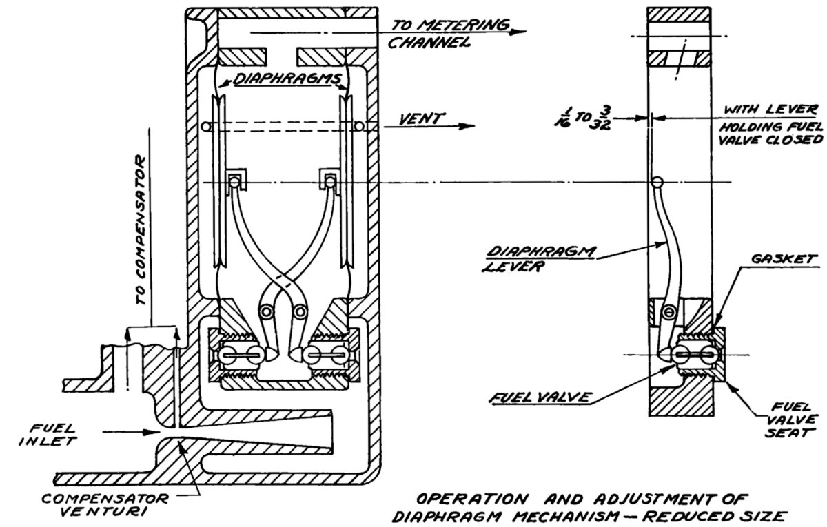 |
| Fig. 54. Holley 1375F Carburetor Diaphragm Mechanism |
The outlet of the fuel chamber is at the top. Suction from the fuel discharge nozzle tends to draw the diaphragms together, which allows the fuel valves to open and admit more fuel. At all times when the engine is running, the diaphragm chamber is completely filled with fuel,eliminating splashing – and the resulting interruption of fuel flow during violent maneuvers. Due to the symmetrical arrangement of the diaphragms, the carburetor functions in inverted flight as well as right side up.
Idle adjustment
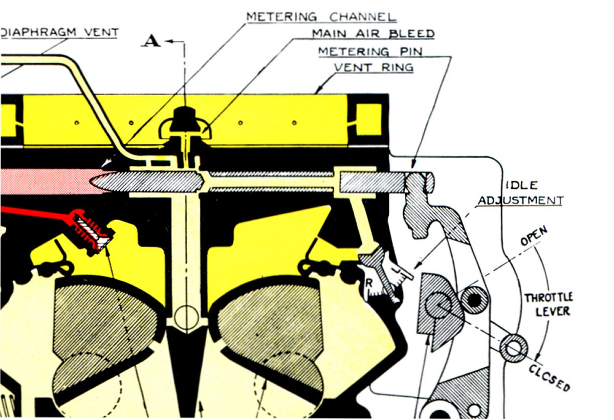
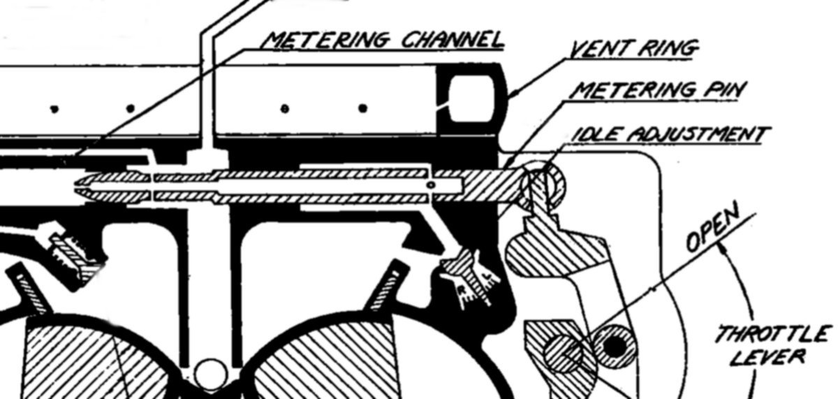
To obtain correct idle mixture, an additional air bleed in the form of an adjustable valve is used. This valve is operative only when the throttles are nearly closed (engine idling) since it bleeds air through a passage in the center of the metering pin which shuts off as soon as the needle is moved out of the seat about 1/16" or more. Thus, the idle adjustment is not effective for engine speeds above approximately 1,000 rpm. The idle adjustment is located near the throttle camshaft on the forward side of the carburetor.
 |
| Fig. 55. Holley 1375F Fuel Metering Pin and Idle Adjustment |
Fuel Metering Pin
The method of regulating the fuel-air ratio of the carburetor is as follows: The main metering channel, which attaches to the outlet of the main diaphragm mechanism, has a restriction and a tapered metering pin. Throttle position controls the position of this pin by means of a cam lever and cam attached to the throttle shaft. The channel and restriction are located in the cross bar above the throttles.
As the throttles open to increase the air passage, the fuel passage opening correspondingly increases to provide the proper fuel flow. The cam profile gives an approximately constant mixture ratio for all throttle openings above the idling range. An air bleed at the center of the main metering channel stabilizes the flow of fuel.
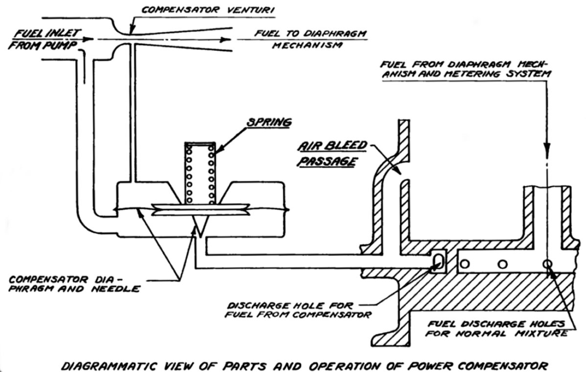
Power Compensator
Holley calls its power enrichment valve a power compensator. It serves the same purpose, adding additional fuel to create a richer mixture for high power operation.
 |
| Fig. 56. Holley 1375F Carburetor Power Compensator Schematic |
As engine power output increases toward its maximum, an automatic enriching device allows extra fuel into the discharge bar. A venturi in the fuel inlet controls the power compensator. When fuel flows through this venturi, the pressure at its throat is less than the pressure at its entrance. The greater the fuel flow through the venturi, the greater the difference in pressure between the entrance of the venturi and the throat. This difference in pressure operates a spring-loaded needle valve. When the fuel flow reaches the point where the venturi differential pressure equals the initial spring tension of the power valve diaphragm, the needle valve starts opening. Further increase in the flow through the venturi increases the needle lift. This valve supplies an additional quantity of fuel from the fuel entrance to the compensator discharge nozzle through the external tube located on the rear side of the carburetor.
The diaphragm mechanism and main metering system supply the engine with a "basic" mixture of approximately constant or normal cruising strength, the compensator automatically supplies the additional fuel required to give the richer mixture needed at higher power output. There is no mechanical connection between the power compensator and the throttle mechanism. The operation of the power compensator and the amount that it enriches the mixture governed by the amount of fuel that the engine is receiving through the main metering system of the carburetor. Fuel flow through the main metering system depends upon the horsepower output, as determined by the amount of fuel consumed. Above a certain power output, the mixture enriches automatically, regardless of the throttle opening or altitude. Below this power output the mixture, remains at the normal value for cruising power, also regardless of throttle opening. The power compensator has a tapered needle attached to a flexible diaphragm, and a spring holds it against its seat. The chamber in which the needle and seat are located connects to the fuel supply ahead of the venturi entrance. The other side of the diaphragm connects to the compensator venturi throat located at the fuel inlet chamber. The spring adjustment is set so that the compensator starts to operate at the specified fuel flow through the venturi, and the greater the fuel flow beyond this point of opening, the greater will be the opening of the needle.
The power compensator provides the proper amount of fuel when calibrated at 6 ~ 7 psi fuel pressure at the carburetor. This pressure setting is critical, especially at high power output when the power compensator is operating. Changing inlet fuel pressure only 1 psi will produce a 2% change in mixture when the compensator is operating. There is no effect when the compensator is not operating at low output, and changes in fuel pressure do not then affect the mixture.
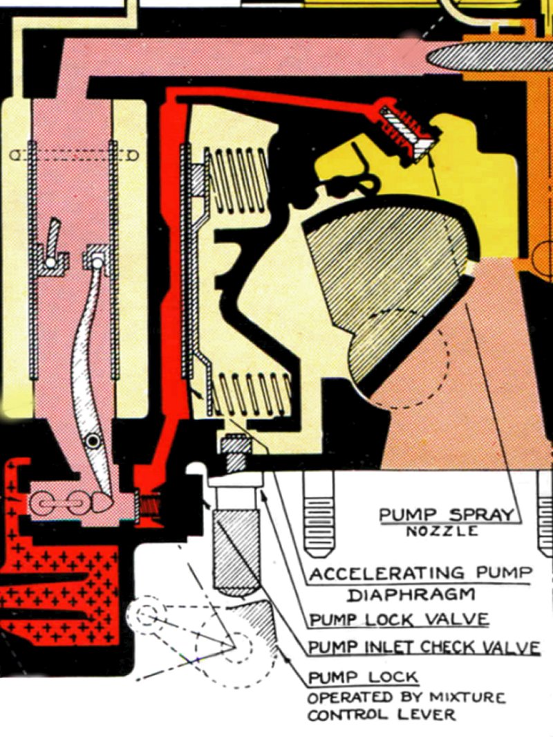
Accelerator Pump
When the throttle is rapidly opened,it is necessary to provide an additional quantity of fuel to insure there is a rapid and positive acceleration of the engine. A vacuum operated diaphragm-type accelerator pump provides this extra fuel. The accelerator pump is located between the main diaphragm mechanism and the body of the carburetor. The complete pump mechanism consists of an inlet check valve, an outlet spray nozzle, a diaphragm, three springs that move the diaphragm, and the pump lock valve. One side of the diaphragm is open to the suction that exists below the carburetor when the engine is running and the throttles are closed. The other side of the diaphragm forms a gasoline chamber with the inner wall of the main diaphragm mechanism. Springs on the suction side of the diaphragm tend to apply pressure on the fuel on the other side of the diaphragm. The inlet check valve is located in the bottom of the main diaphragm fuel chamber and the outlet spray nozzle is located under the metering channel, and directs the accelerating fuel charge down into the air passage of the carburetor. The accelerator pump lock valve in the passage leading to the suction side of the diaphragm, which closes when the mixture control lever moves to the idle cutoff position. This valve prevents pump operation when the engine is stopping. When the engine is idling, the high suction below the throttles pulls the pump diaphragm against the springs, drawing a charge of fuel into the pump chamber through the inlet check valve. When the throttle opens, this suction is broken and the springs expand, creating pressure in the fuel in the pump chamber, discharging it through the spray nozzle. The action of the pump is automatic, with no mechanical linkage between the pump and the throttles. This type of accelerator pump cannot prime or flood the engine by opening and closing the throttles with the engine not running.
 |
| Fig. 57. Holley Accelerator Pump |
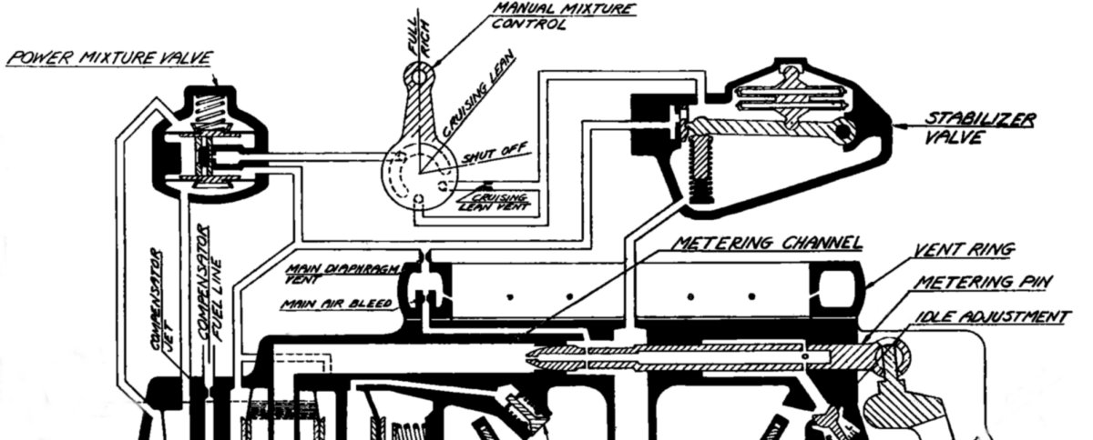
Mixture Control
A manual mixture control permits leaning the mixture to obtain more exact altitude adjustment and improved economy when cruising.
 |
| Fig. 58. Holley Model F Mixture Control |
The actual effect of the mixture control valve is to connect the air space on the outside of the main diaphragms with a percentage of the same suction that exists at the metering needle. This reduces the suction available for drawing fuel out of the diaphragm chamber, resulting in a decreased pressure drop across the fuel metering restriction, providing a decreased fuel flow and a leaner mixture. Varying the area of the mixture control valve regulates the pressure in the air space outside of the diaphragms. In the "full rich" position, this passage is completely closed. As the control moves toward the cruising-lean position, a small slot on the mixture control disc gradually opens. A restriction in the passage connecting the space outside the diaphragms to the vent ring controls the amount of suction. This restriction bleeds off a portion of the suction. The bleed size is such that when the mixture control is in the "cruising lean" position, the mixture strength throughout the cruising range will not be less than the allowable minimum. Movement of the mixture control lever leans out the mixture over the entire range of operation from idle to full throttle.
A further function of the mixture control shuts off the flow of fuel, preventing the engine from after-firing while stopping. Moving the mixture control to its full travel beyond the "cruising lean" stops the engine by exposing the outside of the diaphragms to practically the same suction that exists at the fuel metering restriction. At the same time, pressure applied to the inlet check valve. This locks the accelerating pump, preventing fuel flow into the accelerator pump. With the suction thus balanced, the diaphragms close the fuel inlet valves ending all fuel flow.
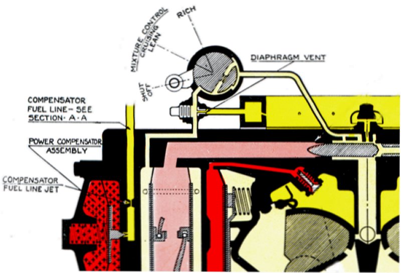
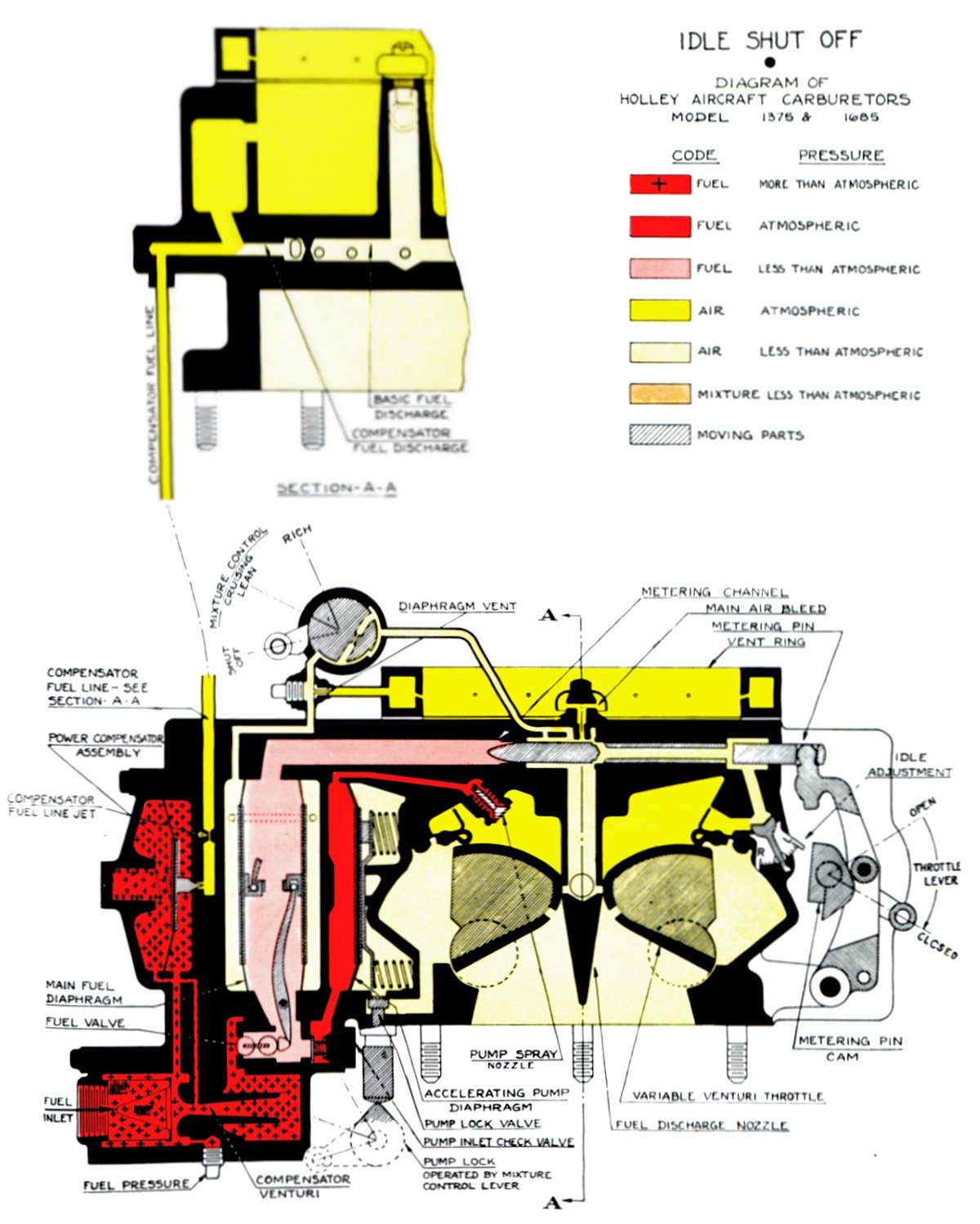
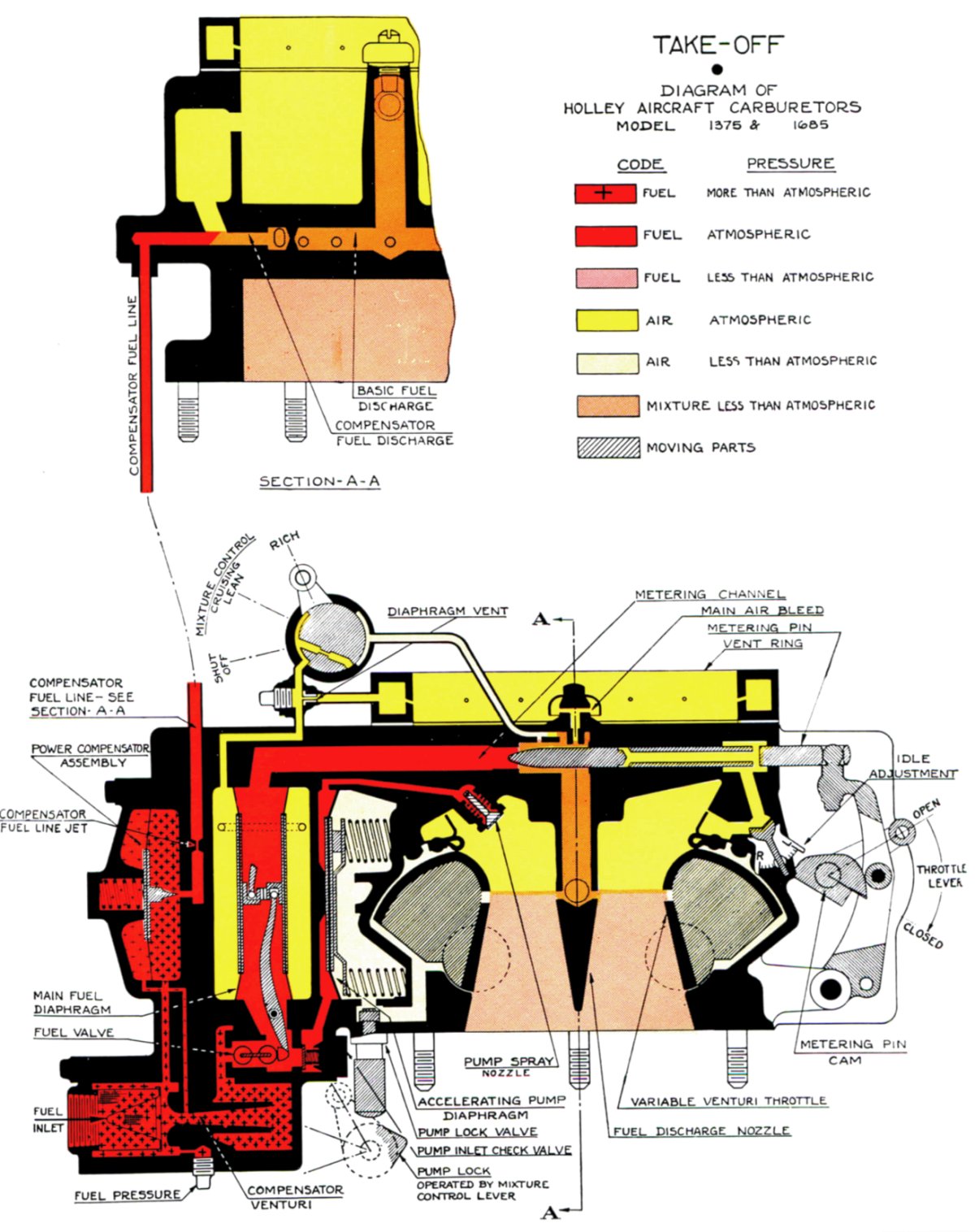
Color Coded Diagrams
The colored charts (Figs. 59 ~ 61) are helpful in explaining the functioning of the Holley carburetor. They are self-explanatory when used with the key color system located at the top of each page. These diagrams apply to the Model F carburetor. The Model H carburetor functions nearly the same, and the changes are shown on a diagram in that section.
 |
 |
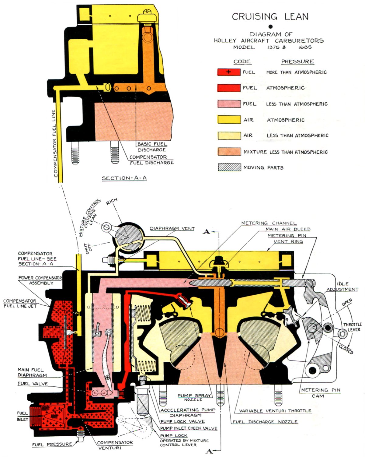 |
| Fig. 59. Holley Model 1375F / 1685F in the Idle-Shutoff Condition | Fig. 60. Holley Model 1375F / 1685F in Takeoff Condition | Fig. 61. Holley Model 1375F / 1685F in Cruise-Lean Condition |
Holley Model 1685-H carburetor
Introduction and Description
The information given for the Model F carburetors also applies to the Model H carburetor, except as noted below. The Model H carburetor retains all of the basic principles and characteristics of the Model F carburetor. In addition, it incorporates several new automatic features and a number of detailed mechanical improvements, all of which make the carburetor more accurate over a wider range of conditions, improve service life, and require less maintenance. Many Model H carburetor constructional details (such as main body construction, cam and needle mechanism, accelerating pump, etc.) are the same as for Model F carburetors.
Stabilizer Valve
The stabilizer valve consists of a slide valve operated through a lever by the movement of sealed capsules at atmospheric pressure and temperature. These capsules expand and contract with variations in pressure and temperature, causing the slide valve to move, acting to regulate the mixture ratio. The slide valve, connected in parallel with the manual mixture control valve, functions in the same manner, i.e., it controls the pressure behind the main fuel diaphragms. The stabilizer functions as a self-operated mixture control valve that responds to variations in altitude, temperature and engine load. The stabilizer is in operation at all times, in the full rich (or automatic rich) and cruising lean (or automatic lean) positions of the manual mixture control. The stabilizer chamber, connected to the discharge nozzle, responds to any conditions that affect the nozzle suction and the flow of fuel.
 |
| Fig. 62. Holley Model H Stabilizer Valve |
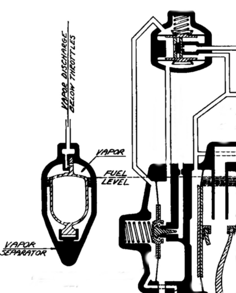
Vapor Separator
Aviation gasoline releases vapor and entrained air when in normal flight operation. This is due to several conditions, among which are the reduction in atmospheric pressure found at altitude, agitation and turbulence caused by the fuel pump, pump relief valve, the bends, elbows and other fittings in the fuel line, and vaporization resulting from any temperature rise within the fuel system. The agitation of the gasoline flowing through the fuel inlet valves of the carburetor causes an additional release of vapor. If allowed to pass through the metering orifice, this vapor is objectionable in that it affects the metering characteristics of the carburetor. Before metering the gasoline in the carburetor, it is necessary to remove all vapors present. In the Model H carburetor, the addition of a float-operated valve placed within the diaphragm chamber accomplishes this task. It was necessary to modify the diaphragm chamber by moving the fuel inlet valves to the top, so that any vapor vents at that point. The fuel exits from the top center of the diaphragm chamber,assuring that only the vapor-free gasoline will go the metering orifice. Any accumulation of vapor in the upper part of the diaphragm chamber will cause the vapor separator float to descend, opening the vapor separator valve, venting the diaphragm chamber to the region below the throttles, which is always at a higher suction than the diaphragm chamber. Removing the vapor causes the fuel level in the diaphragm chamber to rise, causing the vapor separator float to rise with it, thereby shutting off the vapor separator valve. The action of the vapor separator float does not interfere with the normal action of the main fuel diaphragms. The main fuel diaphragms respond to the head or pressure of the fuel pushing against them; the vapor separator float responds only to the level of gasoline within the diaphragm chamber, as determined by the relative volumes of vapor and gasoline present.
 |
| Fig. 63. Holley Model H Vapor Separator |
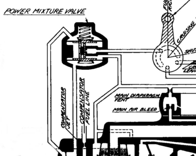
Power Mixture Valve
This valve overrides the action of the manual mixture control valve by automatically restoring the full rich mixture whenever the engine reaches a predetermined percentage of rated power, as measured by the rate of fuel flowing through the compensator venturi. The power mixture valve is in series with the manual mixture control valve, and functions by closing the manual control valve passage. This occurs when the rate of fuel flow through the compensator venturi exceeds the flow rate set by the valve spring pressure. The timing and operation of the power mixture valve is identical with that of the compensator valve. As long as the mixture control remains in the full rich position, the power mixture valve has no effect. For example, if the manual mixture control is set to the cruising lean position and the pilot attempts to use take-off power, the power mixture valve will override the action of the mixture control to provide the full rich mixture required for take-off power. When the power is reduced to below the maximum power permitted for cruising lean operation, the power mixture valve returns to its original position, restoring the cruising lean mixture that existed before the excessive power was applied.
 |
| Fig. 64. Holley Model H Power Mixture Valve |
Idle System
The metering needle used in Model H carburetors has a small hole in the point that supplies fuel for idling. This fuel enters the hollow portion of the metering needle under the pressure differential determined by the position of the idle adjustment valve, which is an air valve similar in construction to that used in the Model F carburetors. The suction within the hollow portion of the metering needle increases as the idle mixture adjustment lever moves to the rich (down) position. This causes a greater flow of fuel through the small idle orifice in the metering needle, providing a richer idle mixture. When the idle mixture adjustment moves to the "up" position, the air bleed valve opens, and the mixture becomes leaner. This revised construction provides approximately twice the range of adjustment obtainable with the idle mixture system used on the Model F carburetor. The idle mixture adjustment valve has a rectangular port opening instead of a round port that used on the Model F carburetor resulting in a uniform change in idle mixture from notch to notch. As was the case with the Model F type of idle system, the Model H type idle system stops functioning as the throttles open beyond the range of idle operation, due to the cross-drilled holes in the metering needle becoming closed by the metering needle bushings as the needle is lifted with increasing throttle movement.
 |
 |
| Fig. 65. Holley Model H Idle Control System | Fig. 66. Holley Model H, HA, HAR Schematic |
Main Air Bleed
The Model H main air bleed mounts in the vent ring, above the diaphragm assembly on the side of the carburetor. In this location, the main air bleed is affected less by variations of pressure in the main air stream as it flows through the carburetor. It is necessary to remove the vent ring to inspect or remove the main air bleed.
Compensator Needle
The compensator needle is a wedge shape instead of the conical type previously used. A spring holds the needle in a recess at the center of the diaphragm allows for some side motion between the needle and the diaphragm, taking up any misalignment. The wedge shape of the needle provides better control over the metering characteristics than that of the conical-type needle.
New Materials
Spring-loaded molded plastic throttle brushes replace the old style leather brushes. This construction provides a more positive seal than that obtained with the leather brushes, and the new construction maintains the seal indefinitely. The metering needle bushings in the metering channel are also made of a plastic material that prevents any possibility of the metering needle scoring as it moves within the bushing.
Chandler Evans Hydro-Metering Carburetor
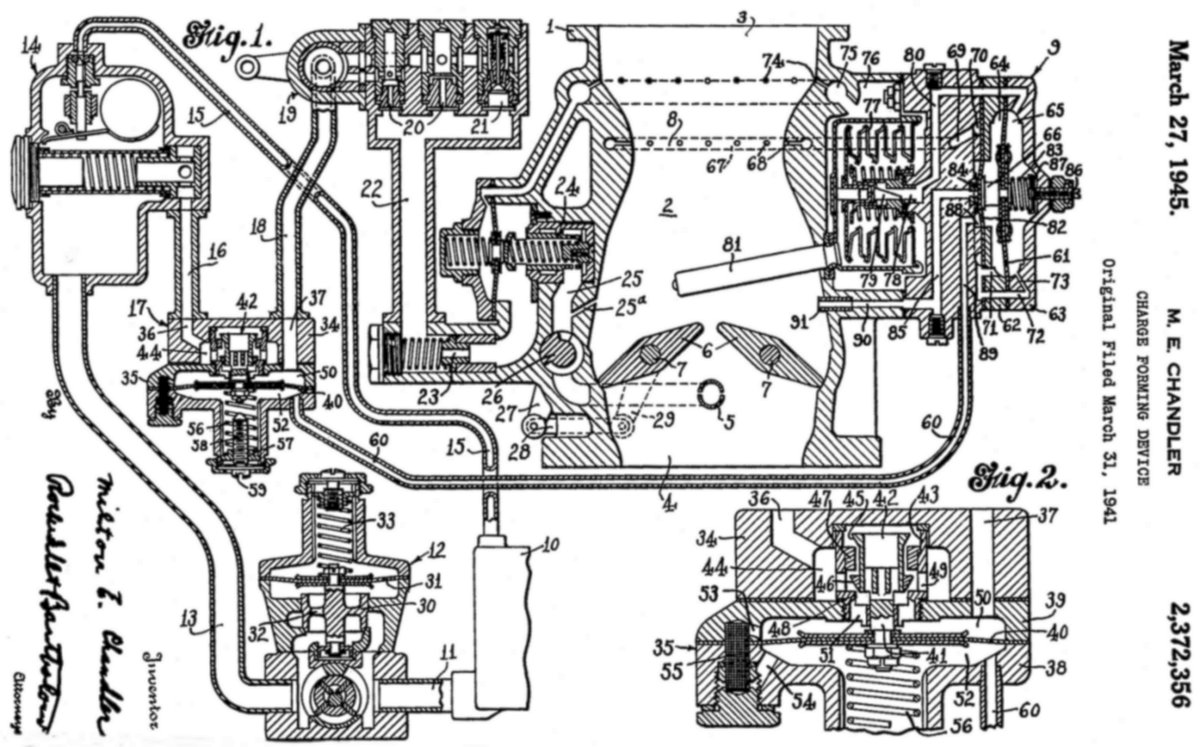 |
| Fig. 67. Milton Chandler's Patent Drawing for the Chandler Evans Hydro-Metering Carburetor |
Chandler Evans Model 58CPB-4 Carburetor
General Description
The Model 58CPB-4 carburetor is a hydro-metering type floatless carburetor used on the Wright R-3350 engine. This carburetor is fully automatic and non-icing to the extent that it has no inherent tendency to create an icing condition.[153]
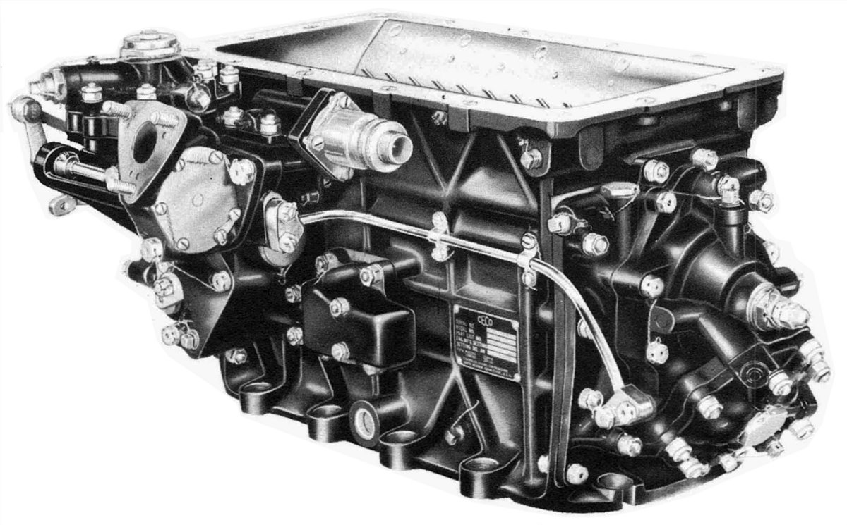 |
| Fig. 68. Chandler Evans (CECO) Model 58CPB-4 Hydro-Metering Carburetor |
Detailed Description
The Model 58CPB-4 Carburetor has five major units, and each unit is disassembled individually.
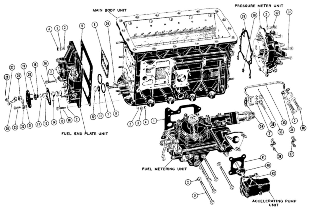 |
| Fig. 69. CECO Model 58CPB-4 Main Units |
Note: The "rear" of the carburetor is the side on which the fuel meter and the accelerating pump are mounted. The terms "left side" and "right side" will mean left and right when looking at the rear.
Main Body Unit – contains the venturi assembly, the impact tubes, the alcohol nozzles, the throttles and the nozzle bar.
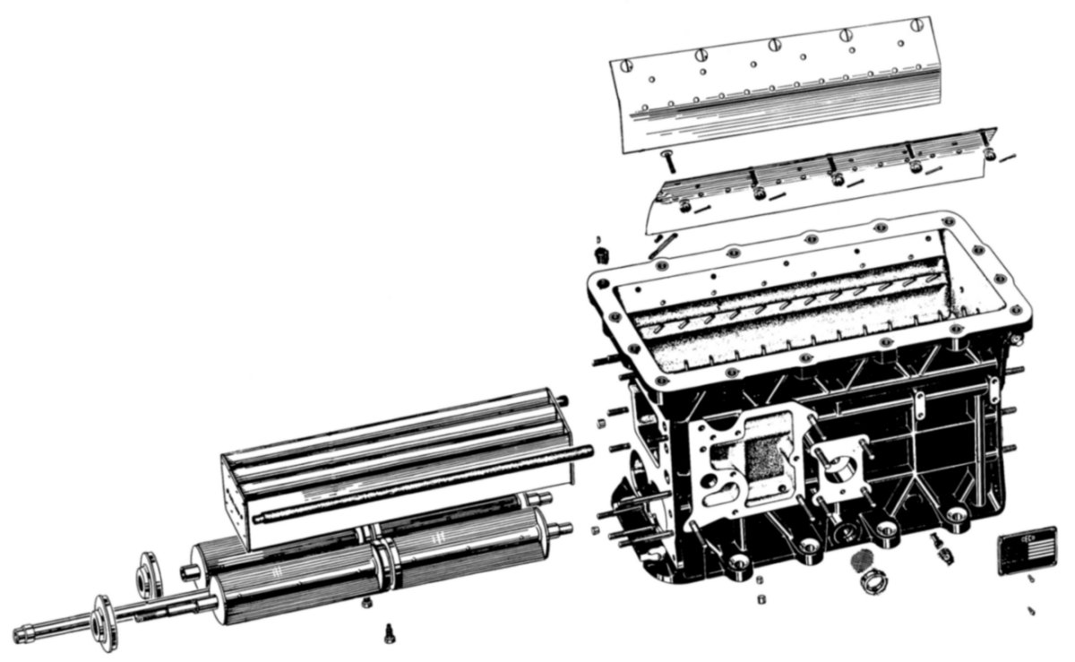 |
| Fig. 70. CECO Model 58CPB-4 Main Body Unit |
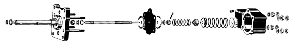
Fuel Metering Unit – attaches to the rear of the carburetor. It contains the fuel inlet cut-off valve assembly, operated by a link connecting the cut-off valve arm to the mixture control. Placing the mixture control in the cut-off position completely shuts off the supply of fuel at the carburetor inlet. A passage drilled through the fuel inlet cut-off valve housing supplies fuel to the primer, mounted on the square pad directly above and in front of the fuel inlet. The fuel inlet chamber has a strainer, attached to a large 5/8" Allen plug below the primer. The chamber has a built-in vapor trap. The vapor trap valve and seat are located on the top of the fuel meter housing, close to the main body. The circular casting at the top of the fuel meter contains a balanced diaphragm-operated pressure regulator valve. Regulated fuel pressure presses on one side of the balance diaphragm. Hydraulic force obtained from the pressure meter presses on the other side. The pressure regulator adjustment spring, the setting of which is controlled by an adjusting screw assembled to the top of the pressure regulator cover, is augmented this force. There are two bosses in the pressure regulator cover, one of which contains the pressure regulator jet assembly,through which fuel from the regulated fuel chamber flows to the chamber above the diaphragm. The other boss contains a pipe plug. Directly below the pressure regulator valve is the jet housing. The jets screw into their respective holders. A triangular plate, secured by a castle nut and cotter pin retains the jet holders. The mixture control valve is contained in a housing mounted on the extreme left side of the fuel meter housing. The mixture control valve is a disc type selector valve driven directly by the mixture control lever. The mixture control detents index the valve at the desired mixture selection.
 |
| Fig. 71. CECO Model 58CPB-4 Fuel Metering Unit |
Fuel End Plate Unit – The left-hand (or fuel end) plate of the carburetor contains the idle valve, a needle valve that is mechanically linked to the throttle. Operating the engine at a high power level withdraws the idle valve from the fuel passage. The load compensator valve is located on the left of the idle valve assembly. This valve, like the pressure regulator valve, is a diaphragm-operated double-seated balanced valve.
 |
| Fig. 72. CECO Model 58CPB-4 Fuel End Plate Unit |
Pressure Meter Unit – attaches to the right hand end plate of the carburetor. It contains the automatic mixture control assembly, which consists of a spring-loaded needle valve operated by a nitrogen filled copper bellows or aneroid. As the aneroid responds to the density of the air, it causes the needle valve to slide in the orifice, thereby metering air pressure within the carburetor. The pressure meter assembly is immediately below the automatic mixture. This assembly is composed of a large diaphragm, against which the air forces are applied. A button attached to the air diaphragm rests against a small fuel diaphragm, causing it to restrict the flow of fuel past the pressure meter seat. The hydrostatic pressure resulting from the restriction at this point is transmitted back to the regulator valve and forms the hydraulic force mentioned in this section. This force is transmitted to the regulator by means of an external tube interconnects the pressure regulator unit and the pressure meter.
 |
| Fig. 73. CECO Model 58CPB-4 Pressure Meter Unit |
Accelerating Pump Unit – mounts in the center of the rear face of the main body. It contains a diaphragm-operated needle valve, controlled by two springs. A small vent plug in the accelerating pump cover permits air pressure developed within the carburetor to become effective on both sides of the diaphragm. The size of this vent controls the time through which the accelerating pump will discharge.
 |
| Fig. 74. CECO Model 58CPB-4 Accelerator Pump Unit |
Principles of Operation
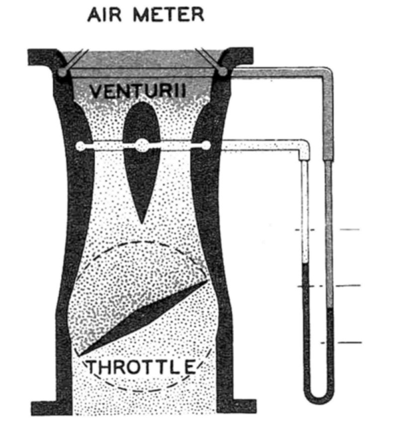
The object of all carburetors is to mix with the air going into the engine the proper amount of fuel for all operating conditions in accordance with a predetermined mixture formula or curve controlled by the carburetor throttle. The quantity of air is measured by means of an air meter and is indicated by the pressure differential between the throat of the' air meter and its entrance. The air meter consists of several ventures in parallel. The throat holes measure the flow of the entire air stream rather than the flow at one point. The fuel metering system controls the amount of gasoline mixed with the air delivered to the engine, operating as a function of the pressure differential obtained from the air meter.
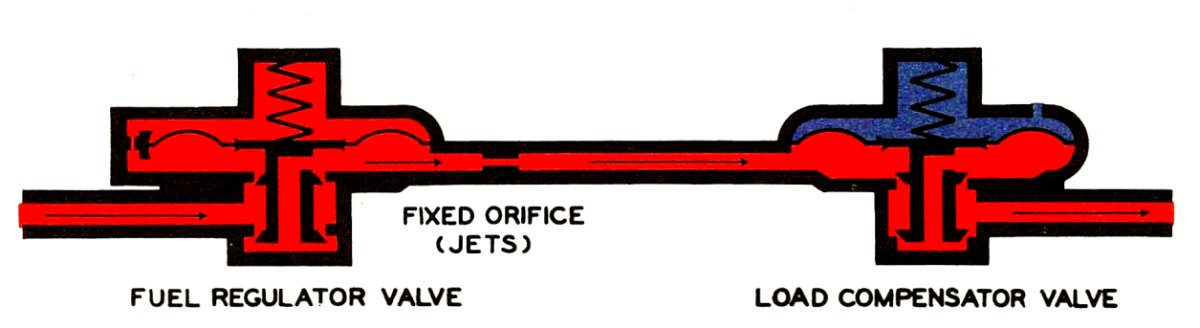
In the hydro-metering carburetor, varying the pressure drop through a system of fixed orifices that are located between two pressure control valves control the quantity of fuel delivered to the engine. This system of fixed orifices consists of four jets, each calibrated to deliver the proper amount of fuel under varied operating conditions. One of the two valves is completely balanced and sensitive only to its spring load. The function of this valve is to eliminate the effect of varying pressure within the engine upon the pressure drop through the jets. The other pressure control valve, called the fuel regulator, reduces the pressure from the fuel pump as a function of the pressure differential force from the air meter and delivers fuel to the jets under varying pressures to vary the resultant flow through these jets.
The pressure meter in this carburetor translates the relatively small air meter pressure differential force into fuel pressure variations at the fuel regulator. In the pressure meter, a hydraulic servo-mechanism multiplies the venturi forces to control the fuel regulator. Bleeding a small amount of fuel into the chamber above the pressure regulator diaphragm augments the hydraulic force. This fuel would, if confined, build up in pressure until it reached the maximum fuel pump pressure. However, this chamber connects to another chamber under the small diaphragm in the pressure meter. In the absence of any force above this diaphragm, this fuel passes through the pressure meter valve and discharges into a passage that conducts it back to the load compensator valve chamber. Here it empties into the main flow of fuel and is discharged into the engine. The small diaphragm in the pressure meter is opposed to the larger one on which the pressure differential obtained from the venturi acts. As airflow increases, this pressure differential increases and tends to exert a force on the pressure meter fuel diaphragm. This increases the fuel pressure in the chamber below the pressure meter fuel diaphragm. This pressure increase passes through the pressure meter fuel line,resulting in a corresponding increase in pressure above the fuel regulator diaphragm. As the pressure increases at this point, the fuel regulator valve will open wider and the pressure above the jet system will rise, causing a proportional increase in the fuel flow.
This carburetor meets all of the fundamental requirements for engine operation, however additional devices to correct for varying density of the air, to provide special fuel requirements for acceleration and additions to the jet system for idle, cruising lean and take-off conditions where special mixture strengths are required. Any change in the density of the air passing through the carburetor will upset the fuel-air ratio. A valve is inserted in the venturi suction passage compensates for changes in air density. A nitrogen-filled bellows that is sensitive to changes in atmospheric pressure or temperature operates this valve. As this bellows moves, the valve slides in its orifice and increases or decreases the effectiveness of venturi suction on the pressure meter air diaphragm.
During rapid acceleration, sudden opening of the throttles allows air to get to the engine much more rapidly than fuel will flow through the carburetor. An accelerating pump takes fuel directly from the carburetor fuel inlet chamber for discharge into the engine. A diaphragm exposed to the intake system pressure below the carburetor throttles operates the accelerating pump valve. Opening the throttles instantly changes this pressure causing the diaphragm to open the valve. An air bleed interconnecting the chambers on either side of the accelerating pump diaphragm controls the length of time required for the pressures to equalize across the diaphragm. When the pressures equalize, the springs return the valve to its seat.
If an engine used only one mixture strength for all operating conditions, one jet would be sufficient. Since it does not, it is necessary to arrange a system using four jets. The A jet is for minimum requirements (cruising lean). The C jet is manually operated and is in parallel with the A jet supplements the fuel flow for normal rich operation (cruising rich). The D jet, also in parallel, is a spring-loaded valve that automatically opens to enrich the mixture when the engine is operating at higher powers. The Band C jets are in series with the D jet. The D jet controls the overall output of the B and C jets, placing a ceiling on the amount of fuel available for maximum power or take-off conditions.
At low airflows and at idle, the desired mixture strength varies from that obtained from the jet system. The idle valve, which is in series with the above-described jet systems,provides mixtures at engine idle speed. The throttle lever controls the idle needle valve, withdrawing it from the passages when the engine operates above the idle range.
 |
 |
| Fig. 75. CECO Fuel Regulator | Fig. 76. CECO Jets and Idle Valve |
 |
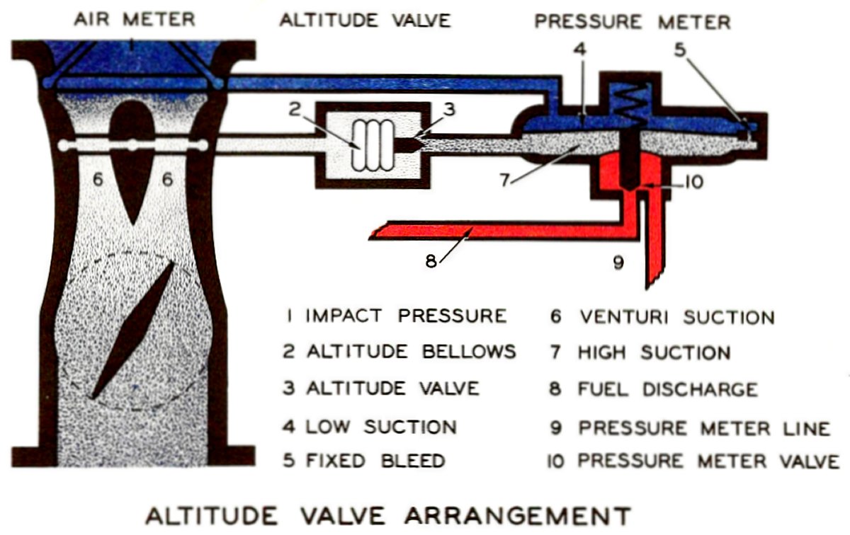 |
| Fig. 77. CECO Air Metering | Fig. 78. CECO Altitude Valve |
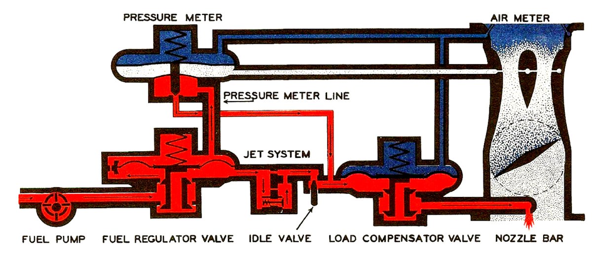 |
| Fig. 79. CECO Hydro-Metering Carburetor Schematic |
CECO Applications
The Wright R-3350 18-cylinder engine used on Boeing B-29s and Lockheed C-69s utilized the CECO floatless carburetor.
Note: CECO's carburetor design never satisfactorily passed the Wright Field tests. Upon the request of the Wright Field engineers, CECO agreed that it would adapt the Bendix Stromberg pressure carburetor fuel regulator assembly to the CECO throttle body. CECO had to pay Bendix a fee for each fuel regulator it produced. Once adapted, the CECO hydro-metering carburetor passed the reliability and performance tests.
Eventually, the Bendix Stromberg direct fuel injection unit replaced the CECO hydro-metering carburetor.
Endnotes
[148] Powerplant Maintenance, p 140
[149] Development of Aircraft Engines, pp 518-52
[150] Development of Aircraft Engines, p 519
[151] Development of Aircraft Engines, pp 520-521
[152] Holley Aircraft Carburetors Instruction Manual p
[153] Publication AN 03-108F-1
Send mail to
![]() with questions or comments about this web site.
with questions or comments about this web site.
![]()