WWII Gunnery Target Engine Technical Analysis
Part 4. Performance and Efficiency Comparison between O-15-1 and O-15-3 Engines
by Tom Fey
Published 19 Jun 2017; Revised 11 Nov 2018
Contents
Part 1. Background and General Configuration
Part 2. The Righter 2-GS-17 (O-15-1) in Detail
Part 3. The Righter O-15-3 Engine
Part 4. Performance and Efficiency Comparison between O-15-1 and O-15-3 Engines
Part 5. The O-45-1 and Kiekhaefer O-45-35
Part 6. Performance and Efficiency Comparison between O-45-1 and O-45-35 Engines
Part 7. Conclusion
O-15-1 and O-15-3 Performance and Efficiency Comparison
The traditional method for raising the power of an engine of a fixed displacement is to spin it faster and/or increase the compression ratio. The O-15-3 does indeed have a higher compression ratio than the O-15-1, but there are several factors that play a role in the efficiency and perhaps dependability of the O-15-3 versus the O-15-1.
The compression ratio in a two-stroke engine is not quite as straight forward as in a four-stroke engine. The nominal compression ratios, as stated in the manuals, are 6 to 1 for the O-15-1 and 7 to 1 for the O-15-3. However, if you actually measure the compression ratio, the static compression ratio (swept volume BDC to TDC divided by head space at TDC) of the O-15-1 is 5.5 to 1 and the O-15-3 is 6.2 to 1. And most relevant, if you measure the compression ratio using the dynamic swept volume (close of exhaust port to piston TDC), the dynamic compression ratio for the O-15-1 is 4.0 to 1 and the O-15-3 is 4.2 to 1. The 0.2 unit (5%) increase in dynamic compression ratio over the 0-15-1 is due to the longer connecting rod in the O-15-3. If you calculate the horsepower per in³ of dynamic displacement, the O-15-3 is 45% higher than the O-15-1 (0.58 versus 0.40, respectively). The 0-15-3 engine generates 11.1 lb/ft of torque compared to 8.6 lb/ft for the 2-GS-17, a 29% increase.
So where and how did the 0-15-3 produce the extra 1.75 horsepower? In reality, the power sections of the 0-15-1 and 0-15-3 are very similar in design and dimensions, and the increase in compression ratio for the 0-15-3 is modest at best. The surface finish and consistency of the die cast cylinder passages in the 0-15-3, as well as the slightly larger port area, likely contribute to the improved performance over the 0-15-1. I further speculate that a significant portion of horsepower differential between the 0-15-1 and 0-15-3 engines was that the 0-15-1 had to overcome the inertia and mechanical drag of the gearbox components with three additional gear meshes, seven extra ball bearings, and viscous oil lubrication, while the 0-15-3 did not.
The rather modest dimensional increase in transfer/exhaust port widths found in the rectangular-port O-15-3 cylinder compared to the O-15-1 result in a 20% increase in area for the exhaust ports for the 0-15-3. Interestingly, the round port O-15-1 and O-15-3 cylinders have significantly less area (0.609 in² sum exhaust) than either the O-15-1 (0.993 in² sum exhaust) or the rectangular-port O-15-3 cylinders (1.122 in²). I can only speculate the round port cylinders, which have been found on more than one Herkimer O-15-1 and the O-15-3, were introduced as a faster, cheaper, easier to manufacture alternative to the rectangular port cylinder, and that the reduction in breathing performance, if any, was outweighed by the reduced cost or ease of production.
When I measured the cylinder fin surface area, excluding the exhaust stack, for the O-15-1 and O-15-3 cylinders, I found a slight difference between them: 2.79 ft² total for the O-15-1 versus 2.56 ft² for the O-15-3. While this may be due to inaccuracy of measurement, the real purpose of this exercise was to establish fin heat rejection area per horsepower developed. Considering only the cylinder fin area, the O-15-1 offers 0.43 ft² to dissipate the heat of one horsepower while the O-15-3 has 25% less at 0.32 ft² per horsepower. The O-15-3 powered OQ-3 does fly faster than the OQ-2, and perhaps both engines have an excess heat dissipation capability, but the ratio of fin area to horsepower becomes more interesting when the O-45-1 and O-45-35 are discussed later in this document.
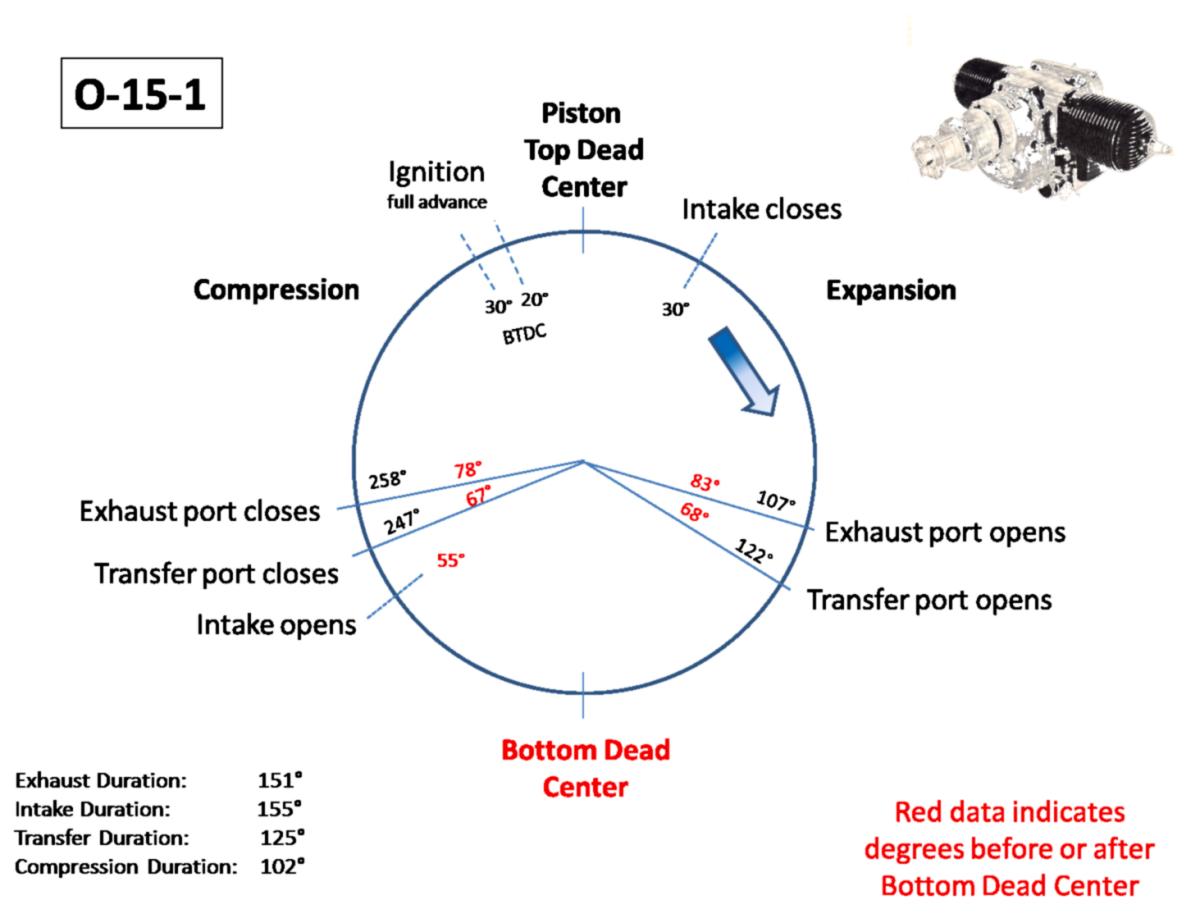
The diameter of the rotary valve as well as the size of the cut-out and orientation of the rotary intake valve on the crankshaft is the same for both the O-15-1 and the O-15-3 at 60° of arc and 1.68 in² of area. Because the connecting rod lengths differ between the engines, the transfer duration (126° versus 125°) and exhaust durations (151° versus 147°) vary slightly between the O-15-1 and O-15-3 engines, respectively.
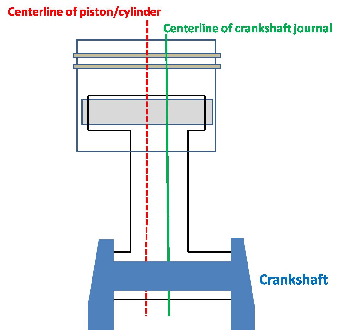
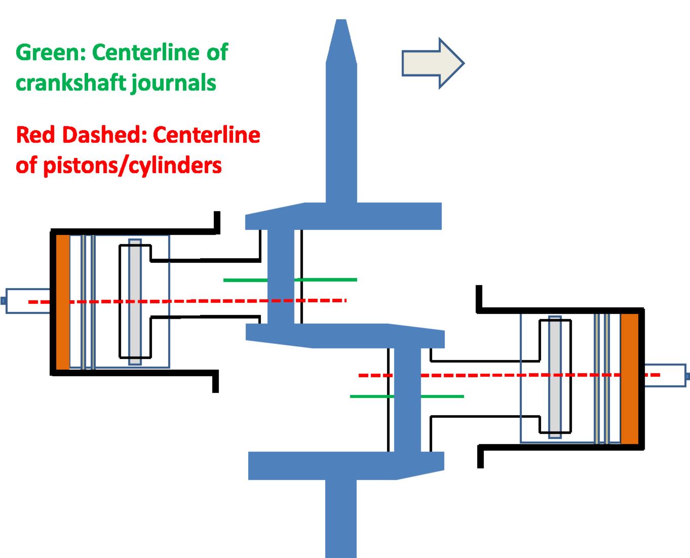
But what was the purpose of the offset rods in the O-15-1? I asked a bona fide engine designer about this and his speculation was that, in effect, it reduced the inertia forces of the pistons, wrist pins, and half the weight of the connecting rod. Because the cylinders do not share a common crankpin, and the cylinders are simultaneously firing, the power pulses from the cylinders are not in perfect opposition. This offset generates twisting moment in yaw to starboard every power stroke, and the magnitude of the moment is proportional to the distance between centerlines of the crankpin journals. The crankpins need to be a certain distance apart for structural reasons, so this dimension cannot be changed. However, the inertia of the reciprocating masses, which is a component of the overall stress and vibration on the engine, can be reduced by the use of the offset rods.
|
|
| Note that the cylinder bore centerline is to the left of the crankshaft journal centerline. This is due to the offset connecting rods. Thus the cylinder bore centerlines can be made closer to each other despite the greater, but structurally necessary, separation of the crankshaft journals centerlines. | Note that the cylinder bore centerlines are closer to each other than the crankshaft journal centerlines. This reduces the rocking (yawing) motion of the crankcase caused by the imperfect opposition of the power pulses. |
There are 63 power strokes per second at 3,800 rpm. Imagine wagging a 12" metal ruler 63 times per second. Then wag a 21" ruler at the same speed. There would be more stress on your wrist, and the far end of the ruler would have a wider oscillation arc with the latter. My speculation is that this inherent vibration became an issue due to the long nose required by the O-15-1 configuration, magnifying the stress and imbalance to the engine and airframe to perhaps destructive levels. The offset rods reduced this dynamic imbalance.
I further speculate that offset was not required in the O-15-3 (or the other drone engines in this study) because the distance from the (nonexistent) center crankshaft bearing to the plane of the propeller was 73% shorter in the O-15-3 compared to the O-15-1 (4.5" in O-15-3 versus 7.8" average for the O-15-1). The vibration still occurred, but was manageable in an engine of overall shorter length. The inherent vibration of this engine design, the susceptibility of radio vacuum tubes to vibration damage, and the potential for harmonic destruction is also why the engines are secured to the airframe by rubber isolation mounts.
Remarkably, the reported fuel consumption went down for the O-15-3 to 1.4 gallons per hour from the 1.6 gallons per hour for the O-15-1 "at best settings". Specific fuel consumption (sfc; pounds fuel/oil mix per horsepower per hour) was reduced 20% from 1.30 for the O-15-1 to 1.08 for the O-15-3. One has to remember that energy is expended in spinning the extra contra-rotating gear box components, the second hub and propeller, and viscous oil drag in the O-15-1 gear case that does not apply to the O-15-3. As a side note, a sfc of 1.08 is quite high compared to a four-stroke engine (Lycoming 0-320 sfc = 0.46), but for the power-to-weight ratio, parts count, and cost of production, the two stroke engine was the best match for this application.
It is hard to know whether the larger big end, thinner piston rings, and ribbed piston of the O-15-3 were introduced to fix problems in the O-15-1, or to preemptively deal with the increased horsepower. Based on recommendations in the Type Test reports, I suspect the former.
In summary, several modest improvements in power section of the O-15-1 design made a significant impact on overall drone performance. The O-15-3 made 8 horsepower from a weight of 19.3 pounds (0.41 horsepower per pound) and was a much more efficient engine than the O-15-1 (6.25 horsepower from 25.5 pounds, or 0.24 horsepower per pound). It had a lower parts count, higher power, and lower fuel consumption than the O-15-1. The airborne differential was that the O-15-3 propelled the (landing gear-less) 97 pound Radioplane OQ-3 to 102 mph, or 16% faster than the O-15-1 was able to pull the 128 pound OQ-2. Power loading was significantly reduced from 18 pounds per horsepower in the OQ-2 to 12.1 pounds per horsepower in the OQ-3. The lower wing loading (5 lb/ft² versus 6.1 lb/ft²) and improved power loading of the OQ-3 gave it a superior rate of climb as well. The only down side of the O-15-3 powered OQ-3 was the torque issue at low airspeed, but proper trim at launch and use of "… only corrective control movements until the target has reached an altitude of at least 300 feet" managed this problem.
O-15-1 Engine Comparison
 |
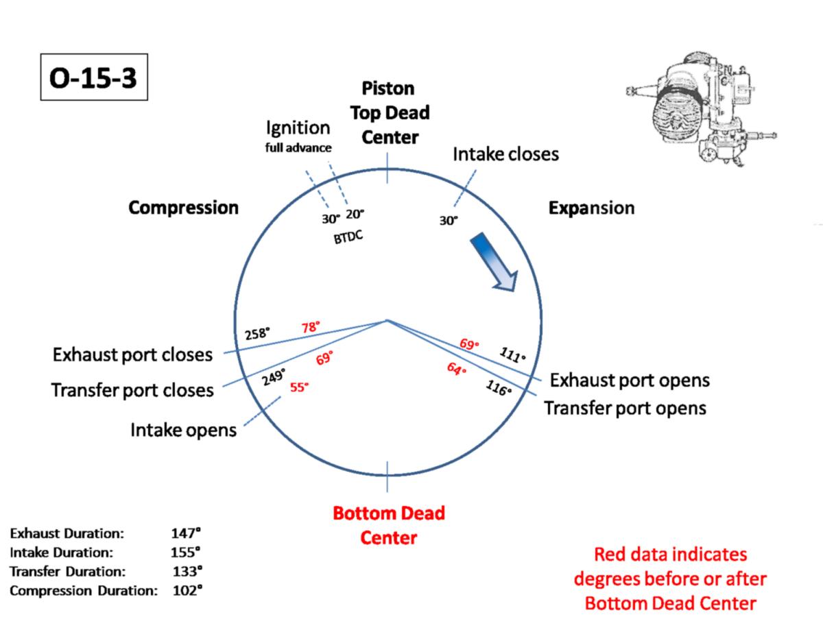 |
| O-15-1 Cycle Timing | O-15-3 Cycle Timing |
| Engine and Cylinder | Engine Swept Displacement (in³ (cc)) |
Bore (inches) |
Stroke (inches) |
Dynamic Stroke (inches) |
Company Nominal Comp Ratio |
Static Comp Ratio |
Dynamic Comp Ratio |
Clearance Volume (in³ (cc)) |
Static Volume (in³ (cc)) |
Dynamic Volume (in³ (cc)) |
Engine Dynamic Volume (in³ (cc)) |
|---|---|---|---|---|---|---|---|---|---|---|---|
| 0-15-1 Sand Cast #6212 Rectangular Port | 16.9 (277) | 2.25 | 2.125 | 1.42 | 6 to 1 | 5.5 to 1 | 4.0 to 1 | 1.89 (30.9) | 10.3 (169) | 7.5 (123) | 15.0 (246) |
| 0-15-1 Sand Cast H-6212 Round Port | 16.9 (277) | 2.25 | 2.125 | 1.42 | 6 to 1 | 5.5 to 1 | 4.0 to 1 | 1.89 (30.9) | 10.3 (169) | 7.5 (123) | 15.0 (246) |
| 0-15-3 Die Cast Rectangular Port | 16.9 (277) | 2.25 | 2.125 | 1.31 | 7 to 1 | 6.2 to 1 | 4.2 to 1 | 1.64 (26.8) | 10.1 (165) | 6.9 (112) | 13.7 (225) |
| 0-15-3 Die Cast Round Port | 16.9 (277) | 2.25 | 2.125 | 1.31 | 7 to 1 | 6.2 to 1 | 4.2 to 1 | 1.64 (26.8) | 10.1 (165) | 6.9 (112) | 13.7 (225) |
| Engine and Cylinder | Engine Cooling Fin Area (in²(ft²)) |
Cooling Fin Tip Gap (inches) |
Cooling Fin Base Gap (inches) |
Cooling Fin Tip Thickness (inches) |
Typical Barrel Fin Depth (inches) |
Outside Diameter (inches) |
Exhaust Stack External Area (in²) |
Weight (grams) |
|---|---|---|---|---|---|---|---|---|
| 0-15-1 Sand Cast #6212 Rectangular Port | 402.3 (2.79) | 0.175 | 0.12 | 0.07 | 0.375 | 4.0 | 15.05 | 1247 |
| 0-15-1 Sand Cast H-6212 Round Port | 402.3 (2.79) | ? | ? | ? | ? | ? | ? | ? |
| 0-15-3 Die Cast Rectangular Port | 368.4 (2.56) | 0.19 | 0.166 | 0.055 | 0.66 | 4.0 | 15.05 | 1056 |
| 0-15-3 Die Cast Round Port | ? | 0.185 | ? | 0.055 | ? | ? | 15.05 | 1134 |
| Engine and Cylinder | Engine Crankshaft Length (inches)* |
Piston Ring Number and Thickness (inches) |
Rear Case Inlet Port Area (in²) |
Rear Case Inlet Port Arc (degrees) |
Intake Transfer Trunk Dimensions (inches) |
Cylinder Transfer Trunk Area (in²) |
Rotary Valve Cut Out Area (in²) |
Rotary Valve Cut Out (degrees) |
Rotary Valve Diameter (inches) |
Rotary Intake Open (° ABC) |
Rotary Intake Open (° BTC) |
Rotary Intake Close (° ATC) |
|---|---|---|---|---|---|---|---|---|---|---|---|---|
| 0-15-1 Sand Cast #6212 Rectangular Port | 15.5 | 2 x 0.151 | 2.48 | 90 | 1.375 x 0.61 | 0.836 | 1.68 | 60 | 4 | 55 | 125 | 30 |
| 0-15-1 Sand Cast H-6212 Round Port | 15.5 | 2 x 0.151 | 2.48 | 90 | 1.375 x 0.61 | 0.836 | 1.68 | 60 | 4 | 55 | 125 | 30 |
| 0-15-3 Die Cast Rectangular Port | 10.67 | 2 x 0.085 | 2.48 | 90 | 1.375 x 0.61 | 0.836 | 1.68 | 60 | 4 | 55 | 125 | 30 |
| 0-15-3 Die Cast Round Port | 10.67 | 2 x 0.085 | 2.48 | 90 | 1.375 x 0.61 | 0.836 | 1.68 | 60 | 4 | 55 | 125 | 30 |
| Engine and Cylinder | Cylinder Transfer Port Area (in²) |
Exhaust Port Area (in²) |
Carb Deck Throat Diameter (inches) |
Intake Duration (degrees) |
Transfer and Exhaust Port Height Difference (inches)* |
Exhaust Port Open (° ATC) |
Transfer Port Open (° ATC) |
Transfer Port Close (°ATC) |
Exhaust Port Close (°ATC) |
Exhaust Port close (°ABC) |
Transfer Duration (degrees) |
Exhaust Duration (degrees) |
Exhaust Port Height (inches) |
Exhaust Port Arc Width (inches) |
|
|---|---|---|---|---|---|---|---|---|---|---|---|---|---|---|---|
| 0-15-1 Sand Cast #6212 Rectangular Port |
0.984 | 0.932 | 1.175 | 155 | 0.12 | 107 | 122 | 247 | 258 | 78 | 125 | 151 | 0.58 | 0.402 | |
| 0-15-1 Sand Cast H-6212 Round Port |
0.61 | 0.61 | 1.175 | 155 | 0.12 | 107 | 122 | 247 | 258 | 78 | 125 | 151 | 0.438 dia. X 4 | 0.440 dia. X4 | |
| 0-15-3 Die Cast Rectangular Port |
1.000 | 1.123 | 1.175 | 155 | 0.12 | 111 | 116 | 249 | 258 | 78 | 133 | 147 | 0.58 | 0.484 | |
| 0-15-3 Die Cast Round Port | 0.61 | 0.61 | 1.175 | 155 | 0.125 | ? | ? | ? | ? | ? | ? | ? | 0.438 dia. X 4 | 0.440 dia. X4 | |
| * From Direct Cylinder Measurement | |||||||||||||||
| Engine and Cylinder | Engine Fin Area (in²(ft²)) |
Fin Area per HP (in²) |
Fin Area per HP (ft²) |
Connecting Rod Length (inches) |
Rod Length to Stroke Ratio | Rated HP @ RPM | Engine Torque (lb/ft) |
Engine HP/Dynamic Volume | Best Fuel Consumption (gph) |
Fuel Consumption (gal/hp/hr) |
Engine Specific Fuel Consumption (lb/hp/hr) |
Oil Ratio | Engine Dry Weight (lb) |
Engine Specific Weight (hp/lb) |
Engine Length (inches) |
Engine Width with Plugs (inches) |
|
|---|---|---|---|---|---|---|---|---|---|---|---|---|---|---|---|---|---|
| 0-15-1 Sand Cast #6212 Rectangular Port | 402.3 (2.79) | 61.8 | 0.43 | 4.25 | 2.00 | 6.25 @ 3800 | 8.6 | 0.40 | 1.60 | 0.26 | 1.30 | 8 to 1 | 25.5 | 0.25 | 16.5 | 19.5 | |
| 0-15-1 Sand Cast H-6212 Round Port | 402.3 (2.79) | 61.8 | 0.43 | 4.25 | 2.00 | 6.6 @ 3800 | 9.1 | 0.43 | 1.60 | 0.24 | 1.40 | 8 to 1 | 25.5 | 0.26 | 16.5 | 19.5 | |
| 0-15-3 Die Cast Square Port | 368.4 (2.56) | 46 | 0.32 | 4.375 | 2.06 | 8.0 @ 3800 | 11.1 | 0.58 | 1.40 | 0.18 | 1.08 | 6 to 1 | 19.3 | 0.41 | 12.0 | 19.875 | |
| 0-15-3 Die Cast Round Port | 368.4 (2.56) | 46 | 0.32 | 4.375 | 2.06 | 8.0 @ 3800 | 11.1 | 0.58 | 1.40 | 0.18 | 1.08 | 6 to 1 | 19.3 | 0.41 | 12.0 | 19.875 | |
- On to Part 5. The O-45-1 and Kiekhaefer O-45-35 -
Send mail to
![]() with questions or comments about this web site.
with questions or comments about this web site.
![]()