WWII Gunnery Target Engine Technical Analysis
Part 2. The Righter 2-GS-17 (O-15-1) in Detail
by Tom Fey
Published 19 Jun 2017; Revised 15 Jan 2023
Contents
Part 1. Background and General Configuration
Part 2. The Righter 2-GS-17 (O-15-1) in Detail
Part 3. The Righter O-15-3 Engine
Part 4. Performance and Efficiency Comparison between O-15-1 and O-15-3 Engines
Part 5. The O-45-1 and Kiekhaefer O-45-35
Part 6. Performance and Efficiency Comparison between O-45-1 and O-45-35 Engines
Part 7. Conclusion
The 2-GS-17 (O-15-1)
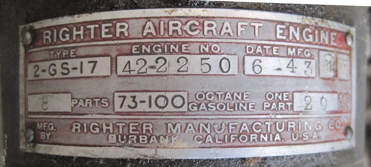
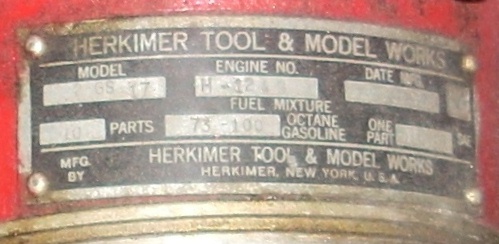
The US Army didn't like the Sidewinder configuration and asked Radioplane/Righter to design an engine that utilized coaxial propeller shafts. The result was the 2-GS-17 (O-15-1) of which at least 3,869 units were produced during war time by Righter Manufacturing Company, Burbank, California, or Herkimer Tool and Model Works, Herkimer, New York. At least one reference states that McCulloch also made the O-15-1, but I have been unable to find any surviving engines, photographs, or documents to support this statement.
The Righter designation "2-GS-17" stands for "2 cylinder, geared, simultaneously-firing, and 17 in³ displacement". The military designation "O-15-1"stands for "opposed; 15 in³ (rounded) displacement; version 1". These two designations were used interchangeably in the various company and military documents, although all the data plates I have seen have the model number as "2-GS-17".
The data plate resides on the top of the curved gear case nose. Fuel-oil ratios stamped on the data plates vary from 5 to 1 SAE 40 oil for early Righter engines, 8 to 1 SAE 30 for the other Righter engines, and 10 to 1 SAE 40 oil for the Herkimer. The details will be explained elsewhere in this document, but the varying ratios are due to recommendations made after their respective 50 hour engine type tests that were completed in early 1943.
|
|
|
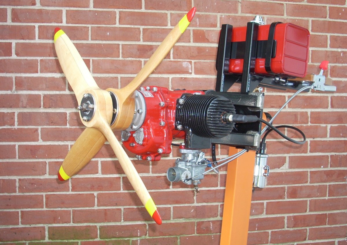
| Restored Righter 2-GS-17 Engine Constructed June 1943 | Data Plate of Righter 2-GS-17 Serial 42-2250 | Data Plate of Herkimer 2-GS-17 Serial H-1248 |
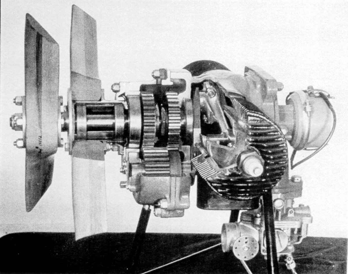
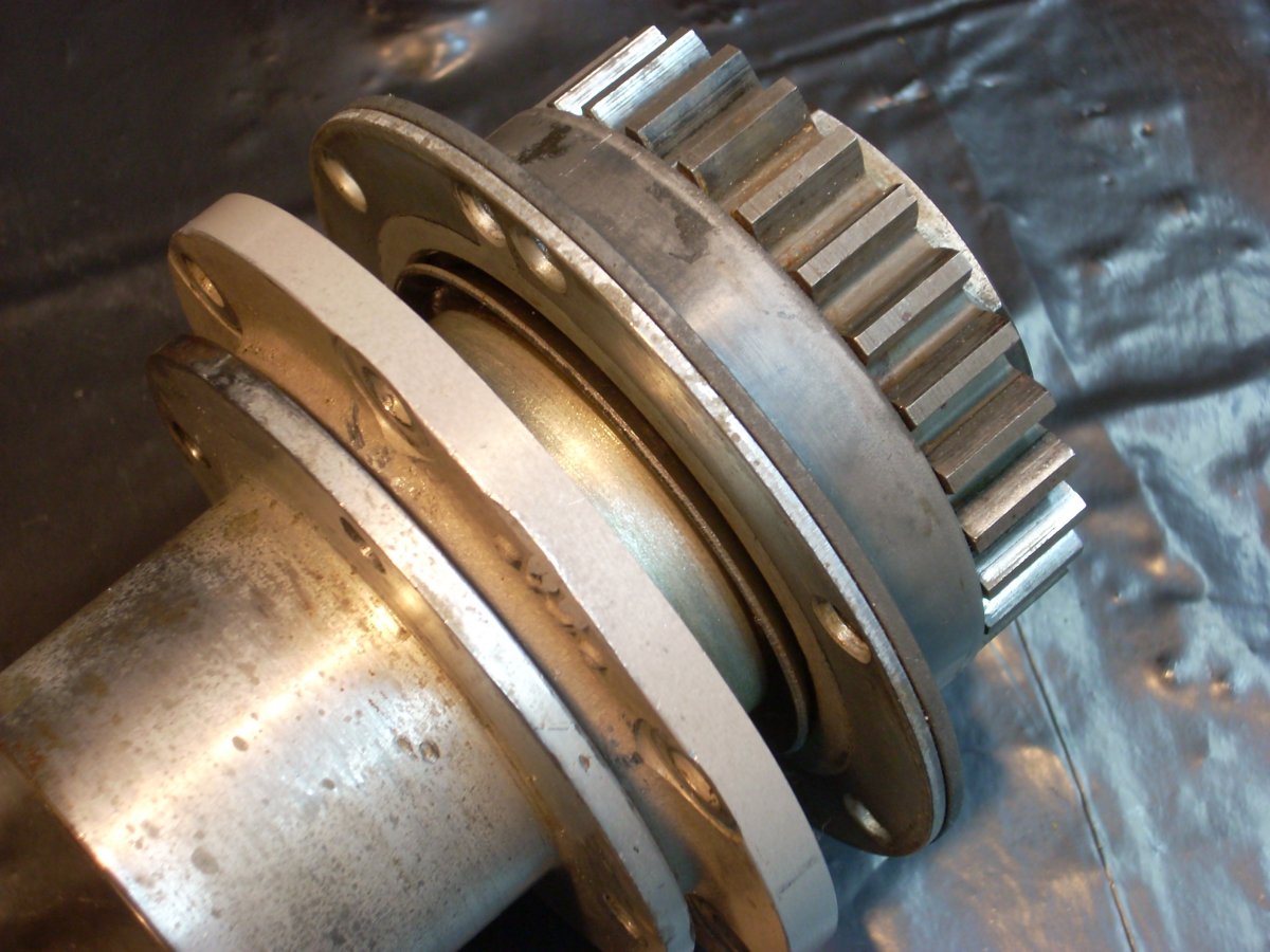
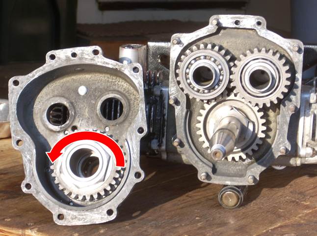
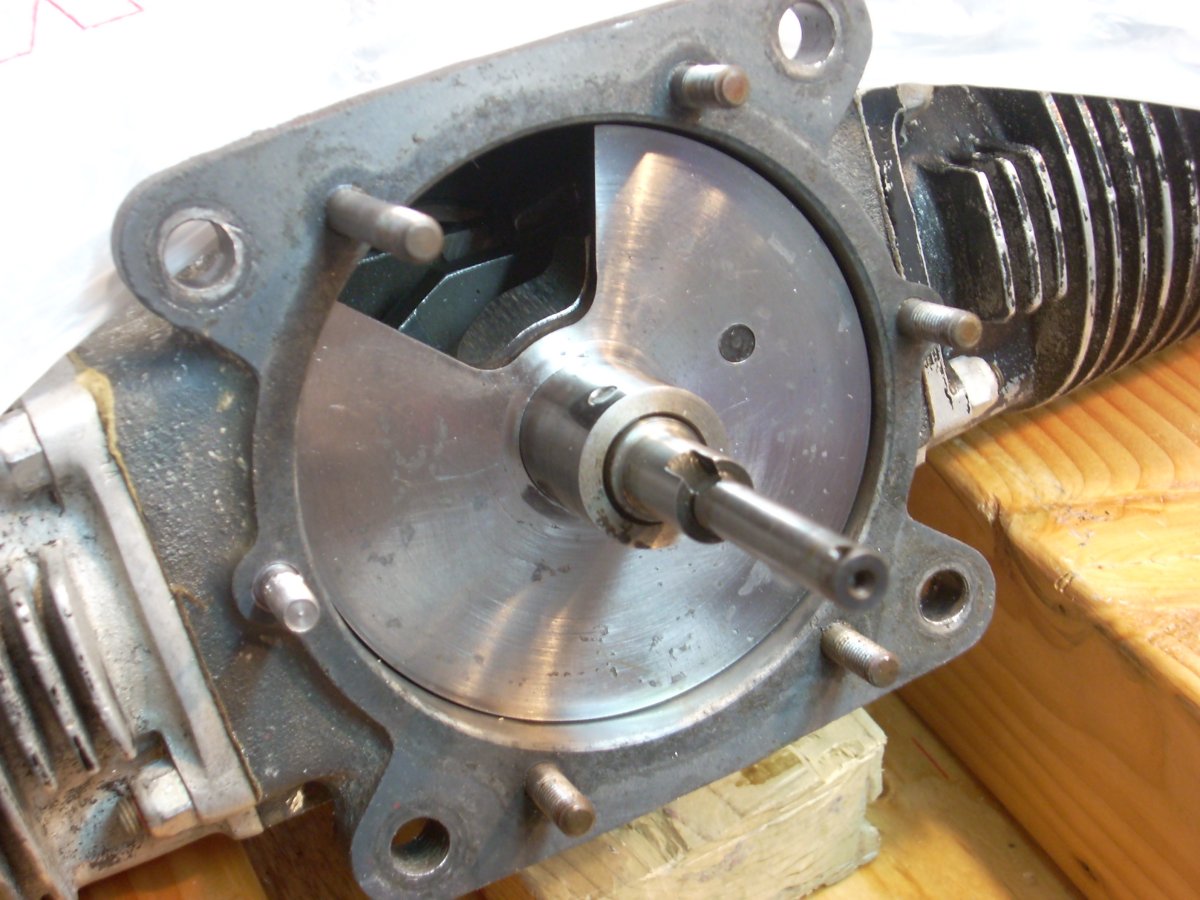
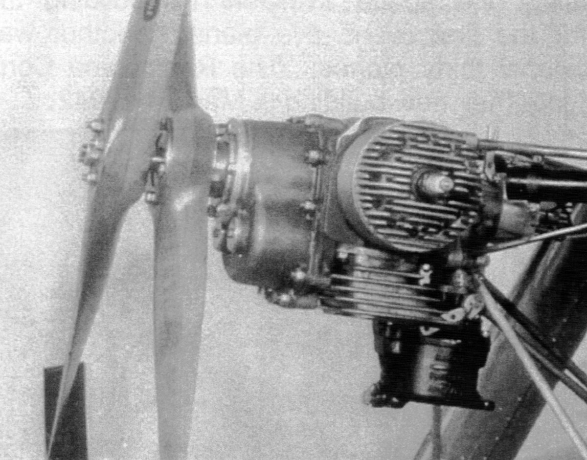
The contra-rotating propeller shafts are the defining characteristic of the O-15-1 engine. Contra-rotation is achieved by a train of ball-bearing supported spur gears in the magnesium alloy gear case. The gear case is sealed from the power section of the engine. The fore propeller is driven directly by the extended nose of the crankshaft and is supported axially by two ball bearings inset in the aft propeller hub assembly. Thrust loads from the fore propeller were taken by a low-profile Marlin-Rockwell ball bearing in the power section of the engine. The aft propeller hub is mounted in the front of the gear case via a large ball bearing that took the thrust loads of the aft propeller.
The gear case contributed no propeller speed reduction, only reversal of rotation. Lubrication is by the passive splash of 2.5 ounces of 70 weight gear oil contained in the case. A hole drilled at the 12 o'clock position in the forward internal mounting flange of the aft hub communicated with a channel in the casting, allowing splash oil thrown from the large drive gear to flow into the hole and down to an oil slinger that directed oil to the main aft hub ball bearing and the two smaller ball bearings that rendered axial support for the fore propeller shaft. There is a top-mounted 1/8" NPT pipe plug for filling the gear case, a lower mid-section plug for overflow, and a bottom-mounted plug for draining the gear case oil.
 |
 |
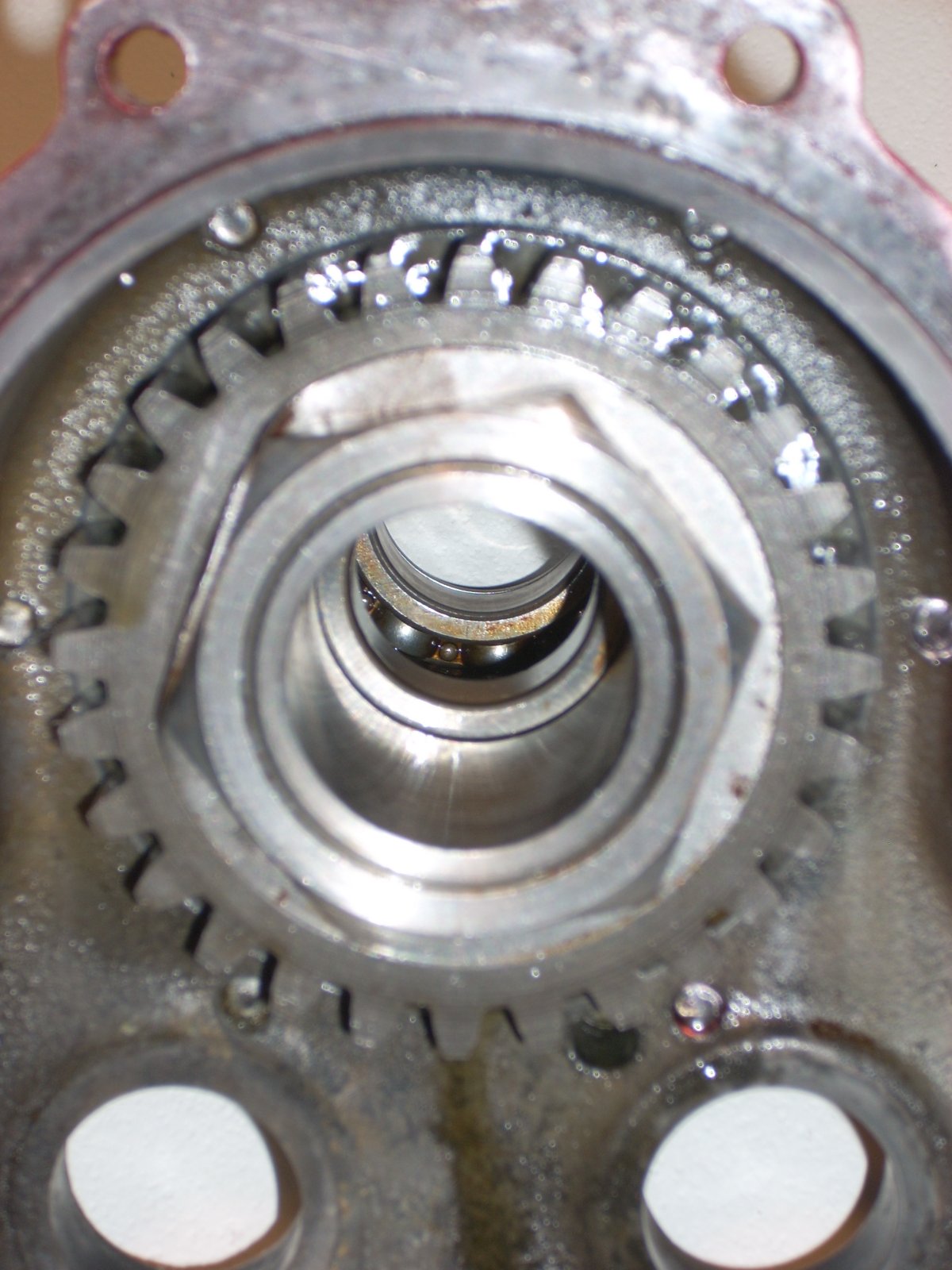 |
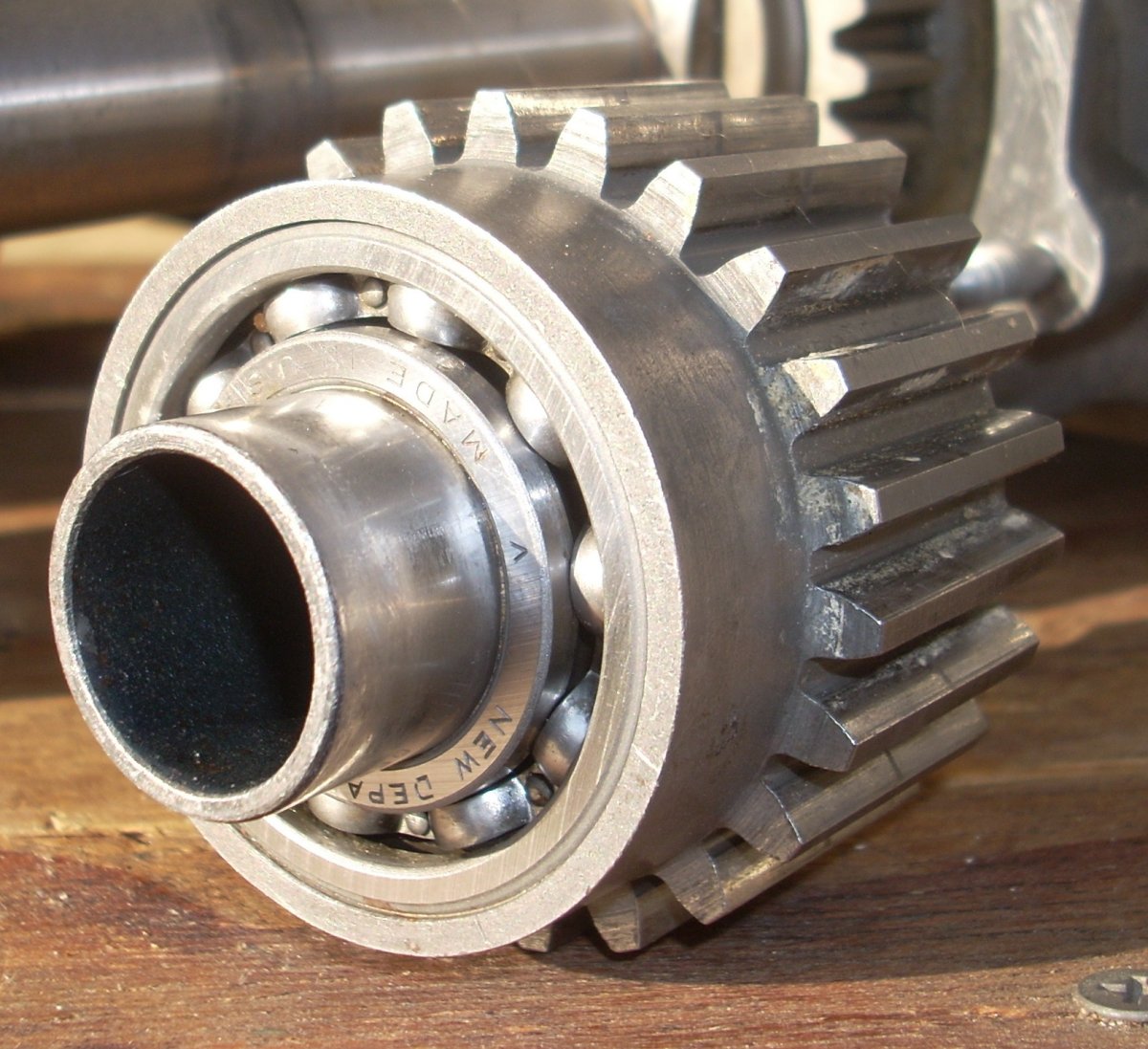
| Cutaway view of the O-15-1 showing, left to right, the dual ball bearings in the hub of the aft propeller that support the forward propeller shaft and the prop hub, the large ball bearing just ahead of the counter gears that supported and took the thrust loads of the aft prop hub, and the thin ball bearing inside the power section that supported the crankshaft and took the thrust loads of the fore propeller. Note the smooth aft third portion of the counter gear that allows clearance for the drive gear while the forward toothed section engages the other counter gear as well as the large driven gear. | Aft hub assembly removed from the gear case. Left to right, aft hub containing twin internal ball bearings (not visible) that locate both the fore prop shaft and the forward part of the aft hub, mounting flange, metal sealing gasket, flared oil slinger, steel thrust bearing housing for aft hub, drive gear for aft hub, (not visible: gear/bearing retaining nut, rear hub gear tabbed lock washer). | Aft hub assembly in gear case viewed from aft showing the dual interior ball bearings that locate the extended crankshaft that drives the fore propeller, aft hub drive gear, retaining nut, and bent-over rear hub gear tabbed lock washer at 10 o'clock. |
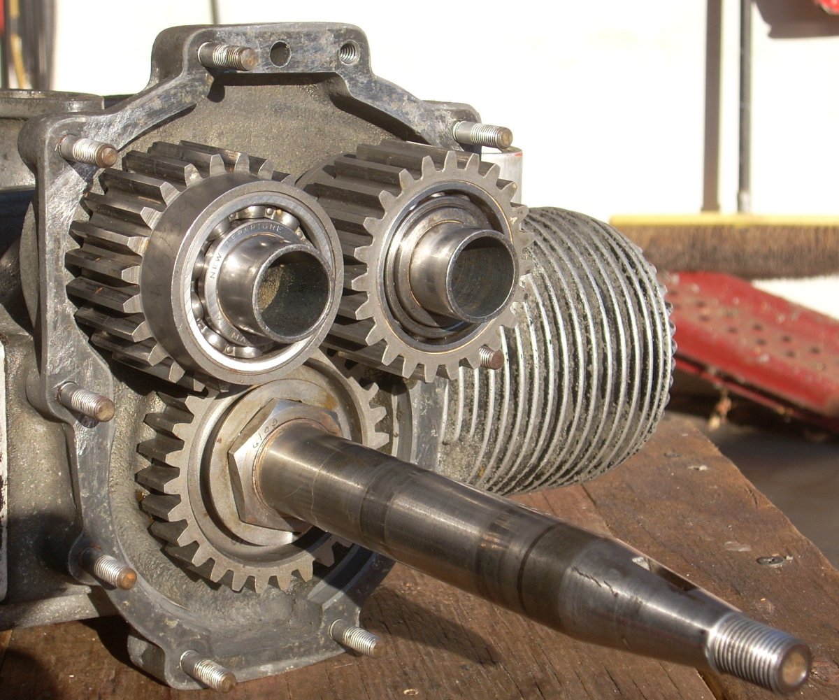
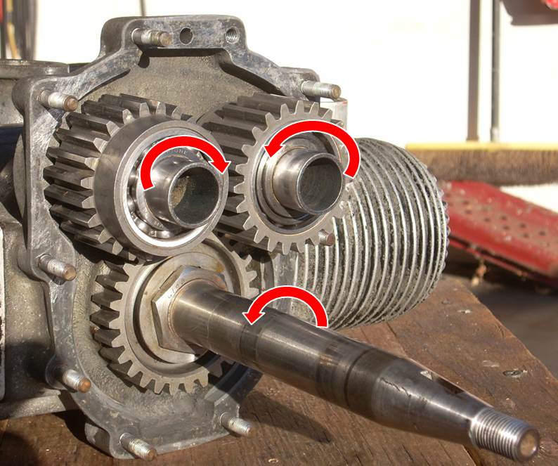
As the crankshaft enters the gear case, there is a large 28 tooth gear that is Woodruff-keyed to the crank, affixed to the shaft by a nut, and locked in place by a bent tab washer. This gear rotates clockwise viewed from aft (VFA) and drives the primary idler gear (23 teeth) counterclockwise VFA. The primary gear meshes with the secondary idler gear (23 teeth), driving it clockwise VFA. The secondary idler meshes with the large 28 tooth gear affixed to the aft propeller hub, driving the aft hub counterclockwise VFA. The idler gears appear over-built for the three horsepower they carry, but this is deceptive because one half of the tooth width meshes with one gear while the other half meshes with the next gear in the train. The idler gears, each supported with two internal ball bearings, are mounted in place by notch-located, non-rotating tubular shaft. The idlers are machined smooth for 1/3 of their width to provide clearance for the fore and aft 28 tooth gears. The contra-rotation system adds approximately 7 pounds to the weight of the engine.
 |
 |
 |
 |
| Open gear case showing extended shaft for the fore propeller and counter gears in place. Large gear on CCW-turning crankshaft drives upper left side counter gear CW. Upper left hand counter gear drives upper right side counter gear CCW. Upper right side gear meshes with large gear on the aft prop hub assembly when it is slid in place over the extended crankshaft, driving the aft hub CW. Engine is shown upside down and viewed from the front of engine. | Gear Path Rotations | Gear case cover containing the aft hub assembly shown on the left slips onto the engine with the extended crankshaft going through the center of the aft hub to drive the fore propeller. Engine is shown upside down. | Idler gear with 23 teeth showing ball bearing support and the first third of the gear width relieved to provide clearance for the larger 28 tooth input and output drive gears. |
Early O-15-1 engines (42-001 to 42-525) have a round cover over the counter gear shafts with a single central bolt to seal the counter gear shafts. Later models of the engine have triangular plates secured by three drilled and safety-wired fillister head screws.
The crankcase is a magnesium alloy casting that has a thin profile, press-fit ball thrust bearing in the forward face to support the crankshaft and take the thrust loads of the fore propeller. The ball bearing is open to the crankcase interior, thus lubricated by the fuel-oil mixture as it runs through the engine.
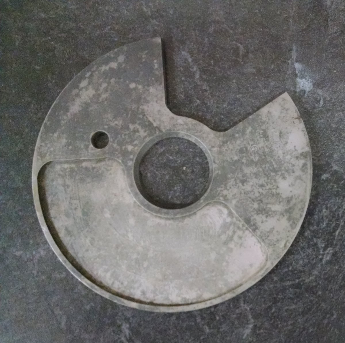
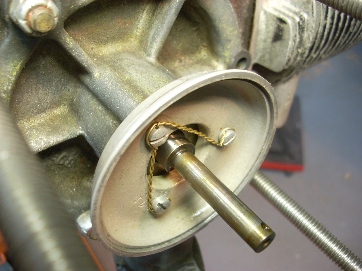
The magnesium alloy engine rear case is bolted to the crankcase via 6 studs with elastic stop nuts. No washers are used under the nuts of any of the crankcase, gear case, or cylinder studs. The forward face of the rear case is machined smooth to mate with the aft-oriented face of the rotary valve induction plate. The latter sits on the crankshaft like a washer on a bolt, and there is an offset spring-loaded peg that both pins the valve to the crankshaft and applies axial pressure to the valve. This axial pressure pushes the valve gently against the smooth face of the tail cover, sealing the intake trunk from the crankcase until the cut out in the valve opens for the induction phase of the stroke. Some O-15-1 rotary valves are smooth on both sides, but some have a relief machined into the crankcase side face opposite of the cut out, presumably for balance and weight reduction.
There is an intake trunk ascending from the updraft carburetor to the induction port in the rear case fore face. The pie-shaped cut-out on the 4" diameter rotary valve is 60° of arc, 1.68 in² of area that provides an intake duration of 155° of crankshaft rotation. Transfer duration (movement of fuel-air from crankcase into cylinder) is 126° and exhaust duration 151° of crankshaft rotation
 |
 |
 |
 |
| Rear case cover with carburetor trunk extending downward and oil seal visible in the center bore. | Interior face of the rear cover showing the intake trunk exit at 6 to 9 o'clock, bronze rear crankshaft bearing, and interior face of the oil seal. | Rear aspect of open crankcase showing the rotary induction valve in place with spring-loaded drive peg at the 3 o'clock position. Not apparent in this the photograph, this valve is smooth on both sides. | Crankcase side of rotary valve showing the milled relief, presumably for improved balance and weight reduction. |
The rear case has a central, pressed-in bronze sleeve bearing that supports the aft end of the crankshaft. A 1/8" diameter hole in the intake trunk connects with a hole bored in the sleeve bearing, thereby allowing induction fuel/oil mixture to flow up vertically to lubricate the aft end of the crankshaft. In the majority of O-15-1 engines (and the subsequent WWII drone engine models) there is also an oblong hole at the 12 o'clock position on the smooth face of the rear case that scavenges oil from the face and directs it down by gravity to a rectangular hole in the sleeve bearing for additional lubrication. A metal-backed, spring-loaded leather National Oil Seal is press fitted into the end of the rear case to make the crankcase air tight.
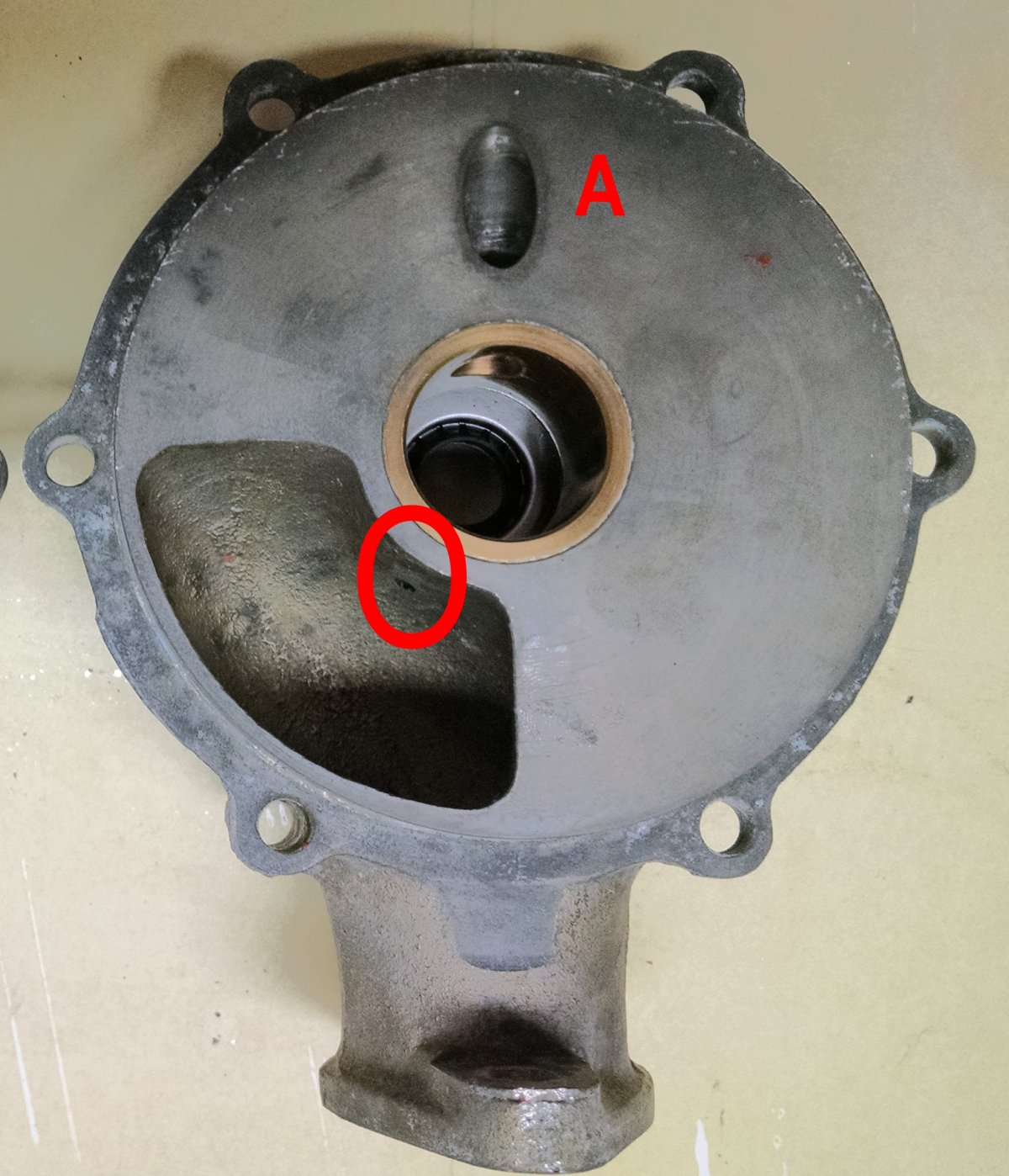 |
| Rear case interior face showing oil channels located on the face (A) and intake trunk (circled) that communicate with the bronze aft crank bearing. |
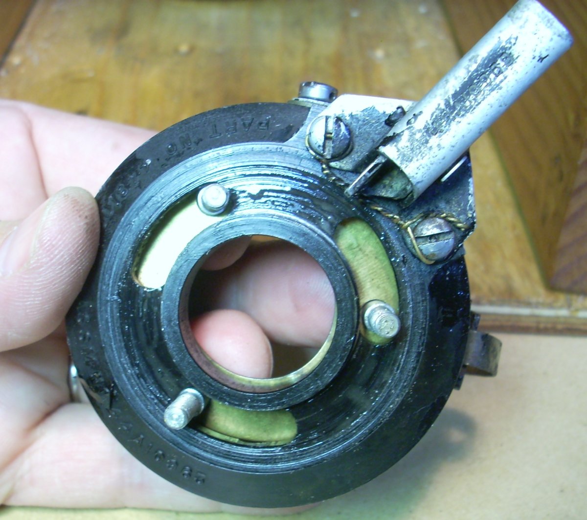
Screwed to the aft face of the rear case is a cylindrical die cast aluminum timer assembly that contains the points, condenser, and ignition advance system. The O-15-1 had two types of timers: the early "1941" series had manual advance providing 30°, and the "1942-1943" series centrifugal advance that provided up to 20° of spark advance starting at 2,000 rpm. The manual system is retained by three screws running in keyhole slots in the timer housing. A central brass spring washer allowed the timer housing to be turned counterclockwise VFA to advance the spark. A lever with spring-loaded pawl is attached to the timer body that engaged a ratchet-tooth bracket (timer rack) screwed to the crankcase to lock the selected position of the timer housing. Inside the timer is a set of adjustable points and the Delco-Remy condenser was attached to a bracket on the exterior of the timer. The tail of the crankshaft is bored to accept a pinned dowel tailored for either the manual or centrifugal timer. The far end of the dowel for the manual timer is machined to a smaller diameter over a 90° segment, and the ramp at the trailing edge of the segment acted as the cam to open the points and fire the spark plugs.
 |
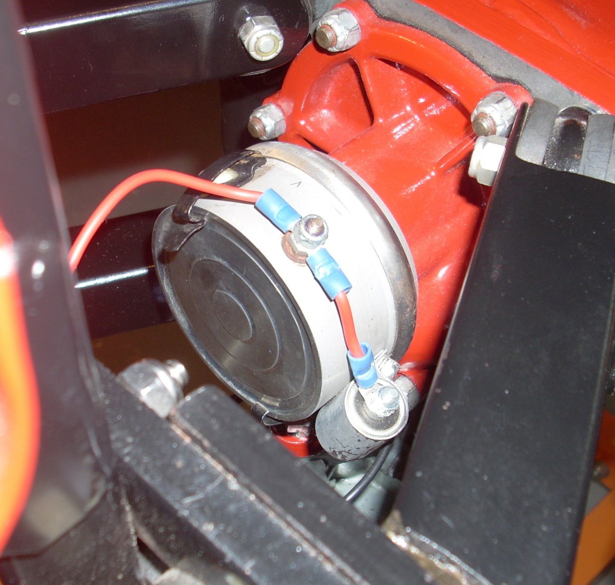 |
| Crankcase-facing surface of manual timer showing the key hole slots that provide 30° of housing rotation as well as the timer lever and pawl at the 1 o'clock position. | Centrifugal Ignition Timer on O-15-1 Engine Aft End. Lead-out wire to coil on left with non-original condenser attached to the timer case on the left. |
The centrifugal timer is very much like that used in automotive practice. The timer baseplate is secured to the crankcase with three screws. The timer housing is attached to the base plate by a U-channel band clamp. Underneath the timer base plate is a set of spring-resisted metal flyweights that engage a rotating sleeve that had a relief ("cam") machined into the periphery. The trailing edge of the relief acted as the cam. Spring action from the points arm kept the pivot arm rubbing block against the "cam". As the rubbing block rode the "cam" the points were kept open. Once the rubbing block dropped into the relief, spring action closed the points, energizing the primary windings. As the rubbing block ramped up to exit the relief, the points opened, firing the spark plugs. As the flyweights moved outward by the centrifugal force generated by increasing engine speed, their pivoting re-indexed the sleeve/cam via their tails in a clockwise VFA direction to advance the spark timing. I speculate that the reason the manual system provided 30° of advance while the centrifugal system provided 20° might be due to the flyweight design or space constraints inside the timer housing.
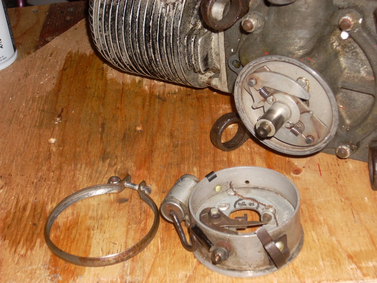 |
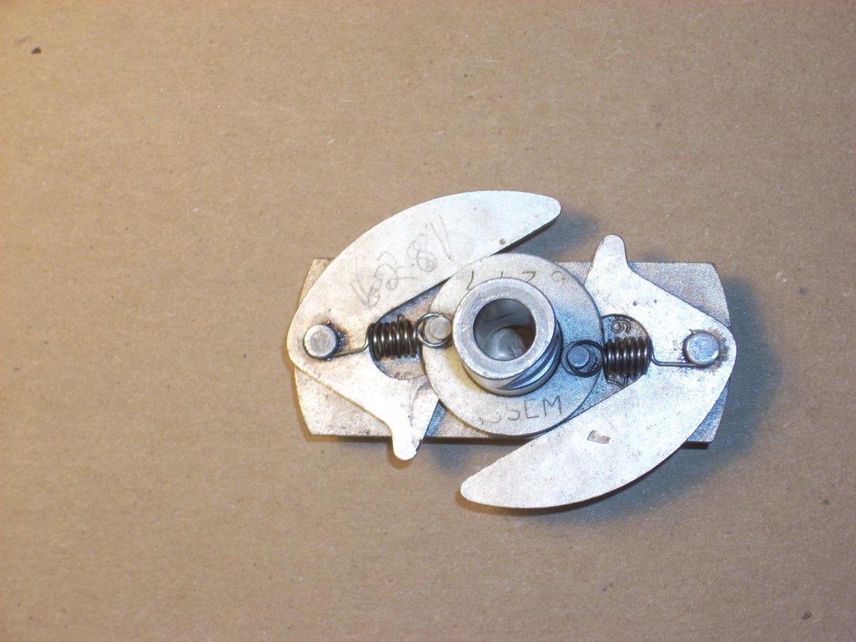 |
 |
| Disassembled centrifugal timer on the O-15-1. Retaining U band on the left, points housing in the center and flyweights in place on crankshaft tail. | Spark advance flyweight assembly viewed from aft. Note the relief cut into the floating sleeve at the 6 to 3 o'clock positions, which allowed the points to close to charge the primary winding of the coil. The "cam" is at the 3 o'clock position, opening the points and firing the spark plugs. As engine speed rose, centrifugal force drove the fish-shaped flyweights outward, whose tails engaged the cam sleeve, indexing it clockwise to advance the spark timing. | Base plate of timer secured stationary to rear case. Flyweight assembly sits on the shaft, driven by a tang that mates with a groove in the crankshaft. The sleeve cam rides freely on the center shaft but is indexed by the flyweights. |
The O-15-1 crankshaft is made from forged nickel steel, measures 15.5" long, and weighs 3.5 pounds. The seat for the thrust bearing is 1.125" in diameter while the aft crankshaft journal and the crankpins are 1.0" in diameter. The crankshaft has cheeks that taper in thickness and width as they near the crankpins. The counterweighted crankshaft is stated to be balanced both statically and dynamically.
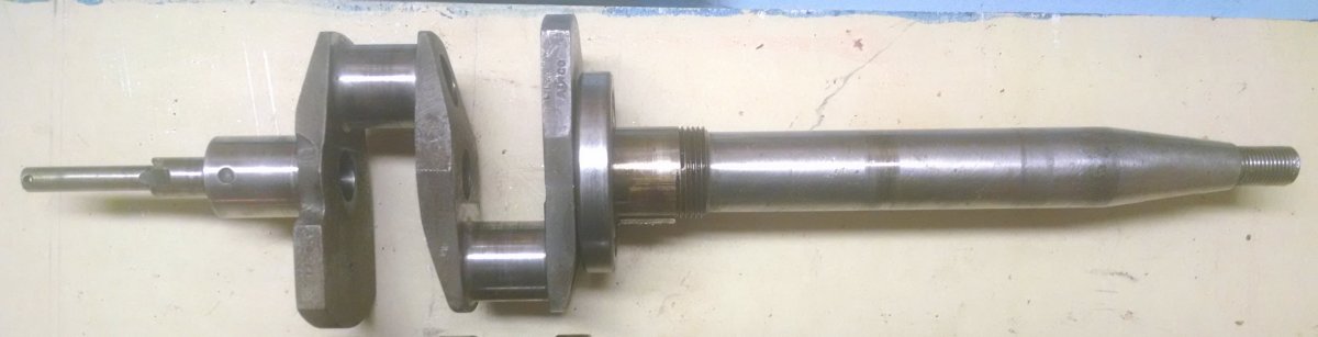 |
| Crankshaft for the O-15-1 engine with centrifugal timer. Note thin profile ball thrust bearing abutting the forward crank cheek and the notch that drives the timing flyweight assembly located at the junction of the smallest and intermediate diameters on the tail of the crankshaft. Note pin securing the dowel in the aft end of the assembly. Threaded section forward of the thrust bearing secures the drive gear for the aft propeller. |
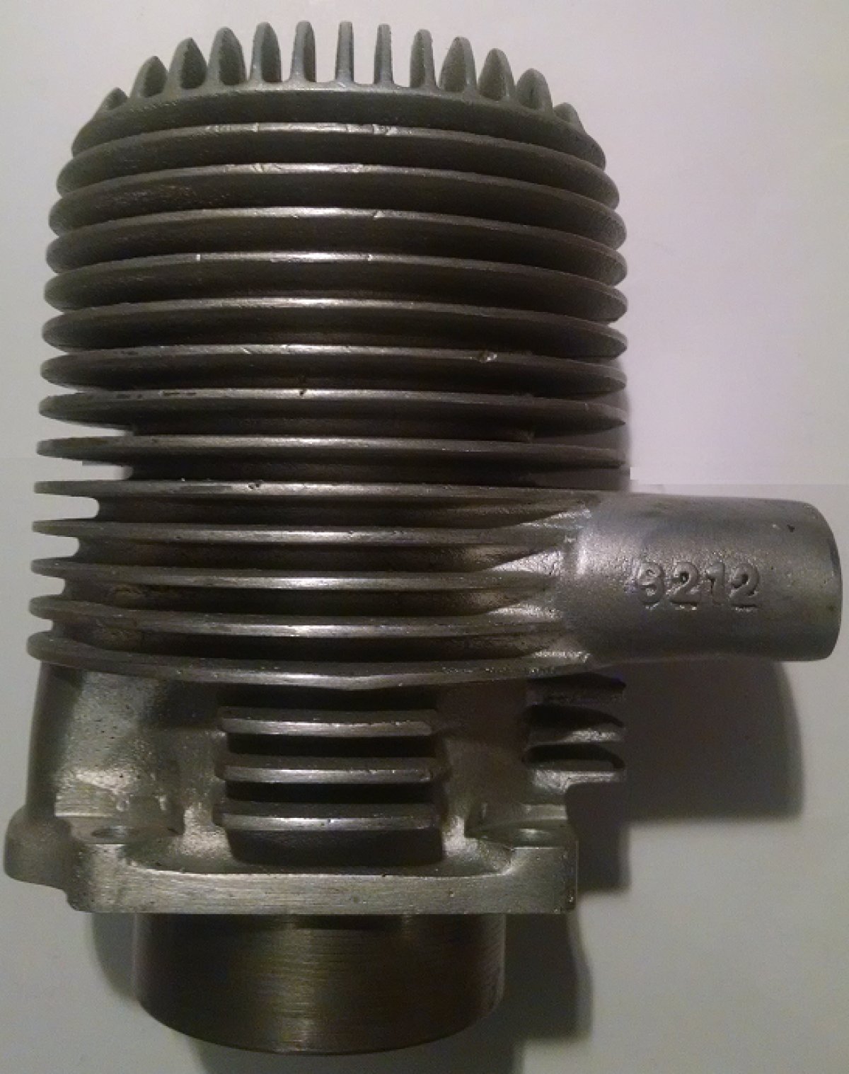
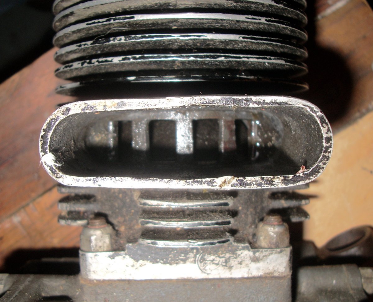
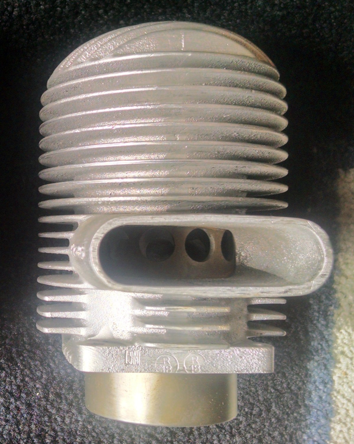
The cylinders (Part #6212) consist of sand-cast aluminum muffs with 0.10" thick cast iron barrels. The cylinder weighs 44 ounces and has a bore of 2.250" and stroke of 2.125". The intake transfer and exhaust ports consist of four identical, radius-cornered rectangles 0.58" tall by 0.402" wide (measured on the arc) with 0.1652" bridges between the ports. The bridges are required to prevent the piston rings from expanding and snagging the port lips and are not backed with aluminum from the cylinder muff. Remarkably, there are also Part #H-6212 cylinders with four identical round ports 0.44" in diameter. Rectangular ports were present in the cylinders on an early Righter O-15-1 engine (serial 42-404), so I'm guessing early O-15-1 engines were rectangular port. As explained later, the "H" in part number "H-6212" may indicate manufacture by Herkimer.
 |
 |
 |
 |
| Righter O-15-1 Cylinder Part #6212 | Rectangular Exhaust Ports on the Righter O-15-1 Cylinder Part #6212 | Round Exhaust Ports on O-15-1Cylinder Part #H-6212. Alignment of sleeve in this particular cylinder is not symmetric with the exhaust stack. | Pre-Production Righter 2-GS-17 with Two-Piece Cylinder and Finned Exhaust Stacks |
By photographic evidence, very early engines had bolted-on cylinder heads and finning cast on the exhaust stacks, but no surviving engines have cylinders of this type.
The spark plug hole is a bronze insert tapped for 18 mm plugs. The timing of the induction valve, transfer, and exhaust ports will be discussed later.
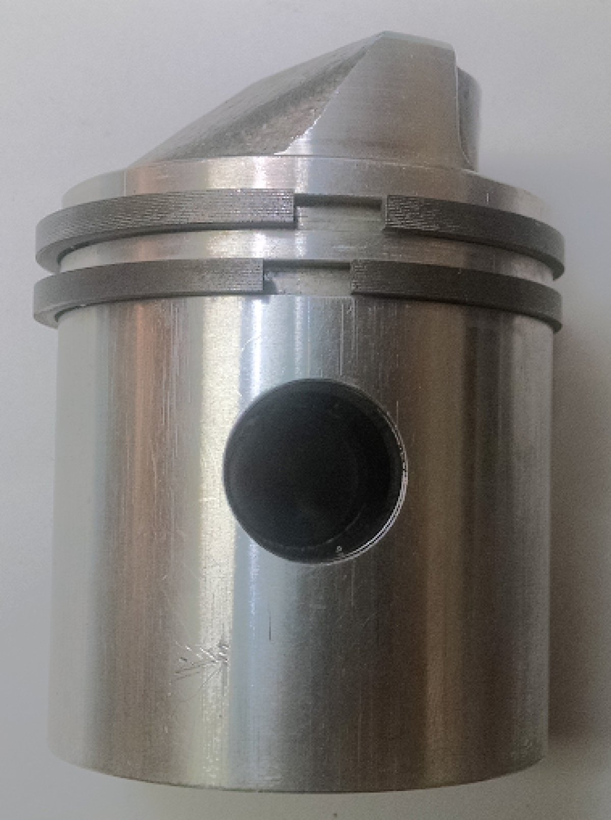
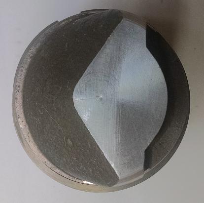
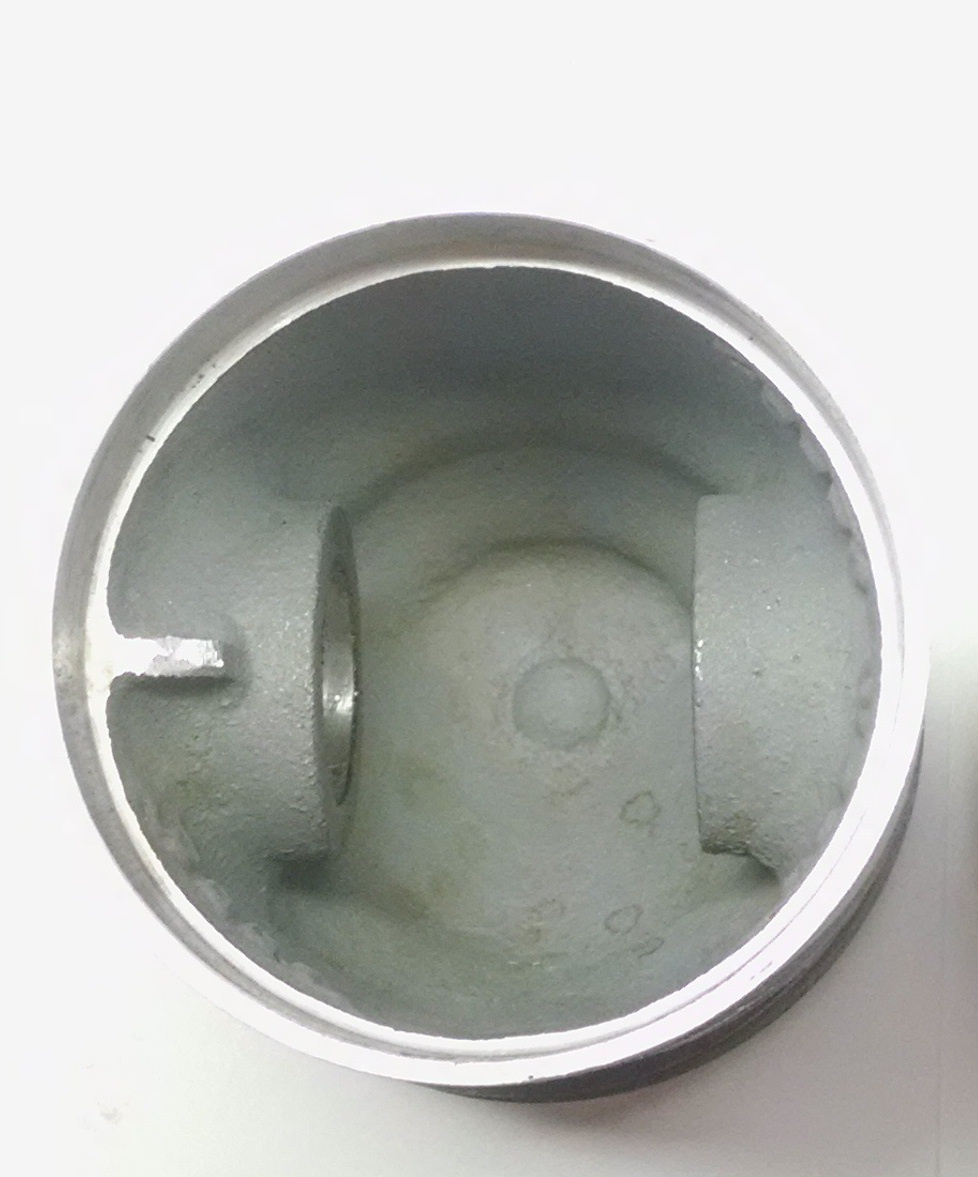
The full skirt aluminum pistons for the O-15-1 are made from "semi-permanent mold castings" and weigh 7.05 ounces each. The piston has two plain cast iron compression rings 0.151" thick and the rings are not pinned in fixed position. The wrist pin diameter is 0.875". The underside of the piston crown is smooth; the piston wall is 0.090" thick with a reduced interior thickness (0.052" thick) for the lower 0.355" of the skirt. The crown is shaped with a vertical baffle to direct the incoming charge to the top of the cylinder and forcing the exhaust gases down the opposing ramp to the exhaust port with minimal mixing of the intake and exhaust streams.
 |
 |
 |
|
| Righter O-15-1 piston showing dual piston rings and shaped piston crown. Scalloped, vertical transfer port face on right, exhaust ramp on left. | Top view of O-15-1 piston showing transfer port face on right, exhaust ramp on left. In operation, gas flow is from right to left. | Underside of the Righter O-15-1 Piston is Smooth |
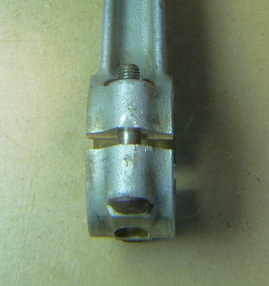
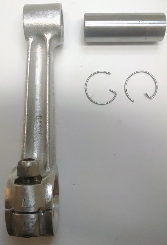
The connecting rods for the O-15-1 are aluminum H-section castings with a full bronze insert for the wrist pin and half shell bronze insert for the big end top as the big end bottom bearing (cap) does not carry load in a two-stroke engine. There is a slot in the little end top, and a large oval cut out in the bearing cap that allows oil to access the bearing surfaces. Broken rods occurred early in development (Memorandum report Dec. 17, 1942) that was likely due to excessive porosity in the casting. The caps are precision machined and matched to the rod with paired stamps to assure proper assembly.
Unique to the O-15-1, the connecting rod centerline and crankshaft journals are not centered on the cylinder bore centerline. Specifically, the crankpin journal centers are 1.31" apart while the cylinder bores centerlines are only 0.7" apart. There is a shoulder on one side of the connecting rod big end, and a shoulder on the opposite side on the little end, that move the piston over to the centerline of the cylinder bore. The reason for this is to "reduce dynamic imbalance" and will be discussed in detail in the O-15-1 versus O-15-3 section of this document.
 |
 |
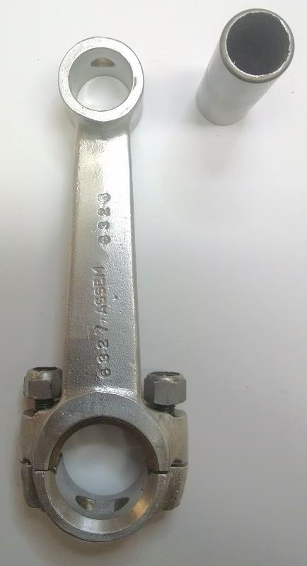 |
| Connecting rod big end showing "T" stamp on rod and cap to assure matched components during assembly (O-15-3 rod is shown here). | Righter O-15-1 connecting rod and wrist pin. Note that the little end centerline is offset to the right of the connecting rod shaft centerline via a shoulder on the right side of the little end. Although difficult to see, the big end centerline is offset to the left of the connecting rod shaft centerline via a shoulder on the left side of the big end. | Righter O-15-1 connecting rod showing the large holes allowing oil to access the writs pin and big end bearing. Note the bronze bearing insert is only in the big end top hemisphere. |
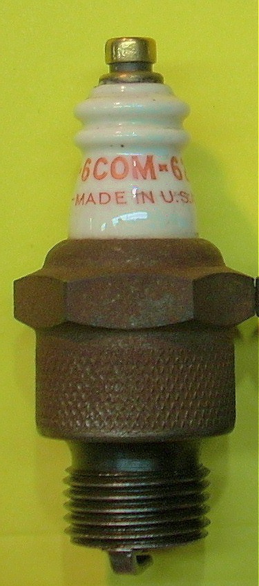
Spark plugs for the 2-GS-17 were Champion 6-COM-62 plugs that were modified to have a slotted, non-removable brass fitting on the end to accept the spring-loaded Rajah style spark plug connector.
 |
 |
| Champion 6-Com-62 spark plug modified at the connector for aircraft use. | Spring-loaded Rajah style connector seats in the groove of the spark plug. |
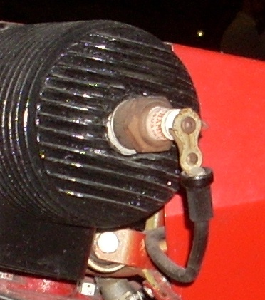
The carburetor for the O-15-1 is the Tillotson YC2B (early models) or YC3A updraft units. Both carburetors have a spring loaded choke, but neither has an idle circuit. While the YC-2B had a ratchet-retained throttle butterfly, the YC3A had no throttle plate. The YC3A does have drilled bosses cast into the body of the carb, sealed with Welch plugs, which makes retrofitting a throttle very easy. These target drone engines were designed to run wide open until they ran out of gas or were destroyed by gunfire. Air-fuel mixture is adjusted by a brass needle valve at the angle of the L-shaped carburetor and proper rpm was measured by ear or with a clockwork-driven Boulin C-1 Strobomcca stroboscopic tachometer.
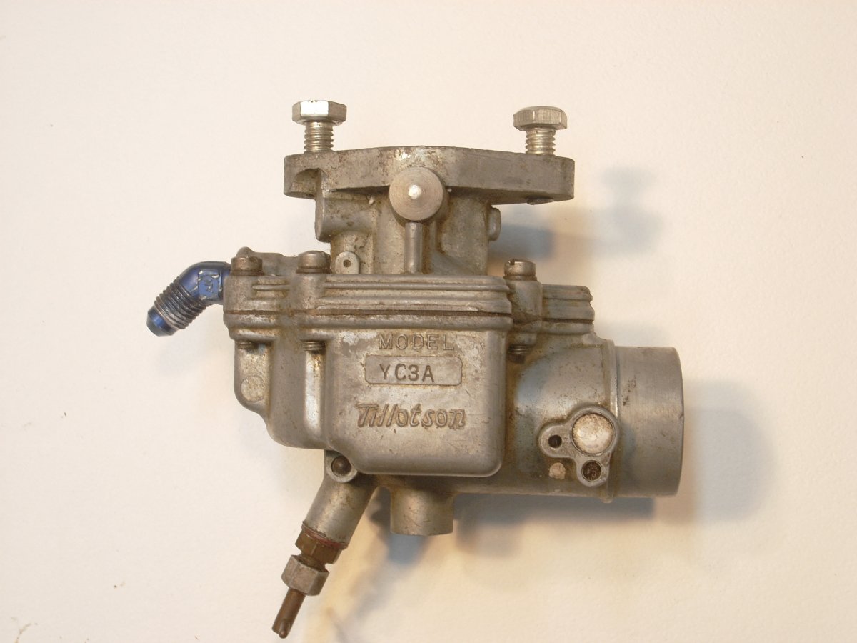 |
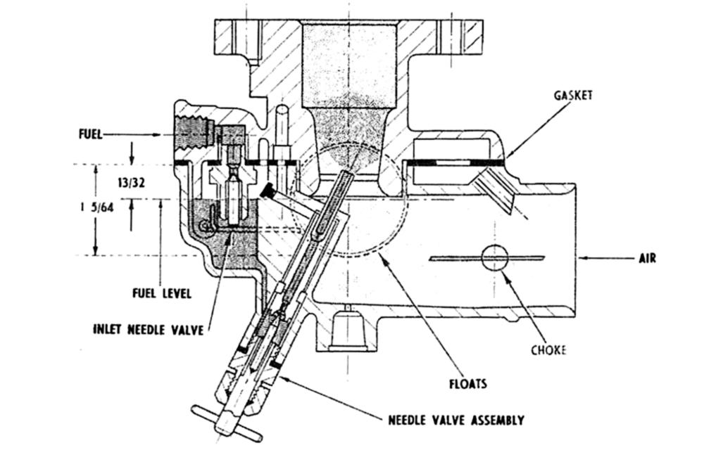 |
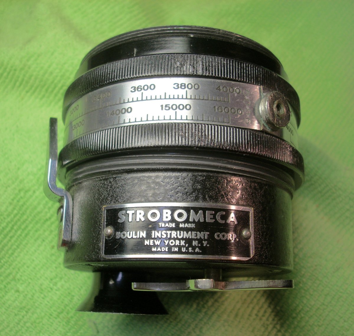 |
| Tillotson YC3A Carburetor | Tillotson YC3A Carburetor Diagram | Boulin C-1 Strobomecca Stroboscopic Tachometer. Clock spring drives a spinning shutter whose speed can be adjusted in a narrow calibrated range to "freeze" the spinning propellers in the viewfinder. Rpm is read off the body of the tachometer. Funnel-shaped viewfinder at lower left and chromed spring winding arm at lower right. |
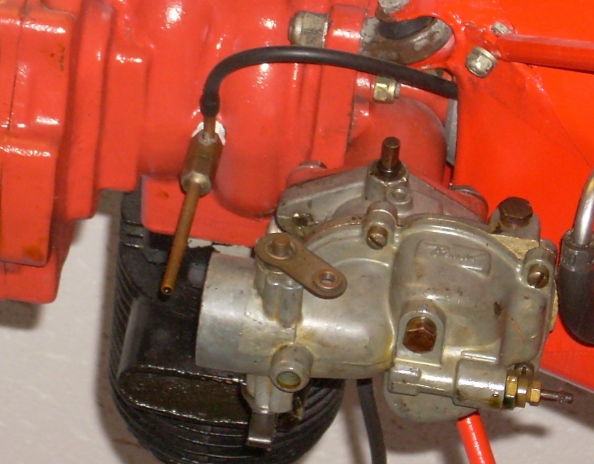
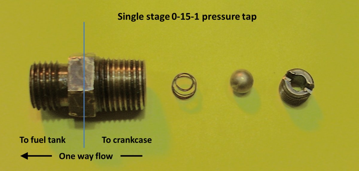
The fuel tank sits in the OQ-2 airframe at approximately carburetor float bowl height, so there is no pressure head. At the bottom center of the crankcase is a tapped hole to accept a "check and relief valve assembly" that taps pressure off the crankcase to pressurize the fuel tank. There is a spring loaded ball that vents pressure if it exceeds 2 psi, and the pressure relief tube exits directly in front of the carburetor intake. Measurement of the crankcase pressure during the type test determined that it never exceeded 4 psi, so on later models of the 2-GS-17, the vent tube was eliminated with a recommendation to change the pressure setting to 0.5 psi. The early pressure taps were disassembled from the crankcase side of the tap, which presents risk should the parts vibrate loose and escape into the crankcase. Taps for the later O-15-1 and subsequent engine types were disassembled from the opposite end.
 |
 |
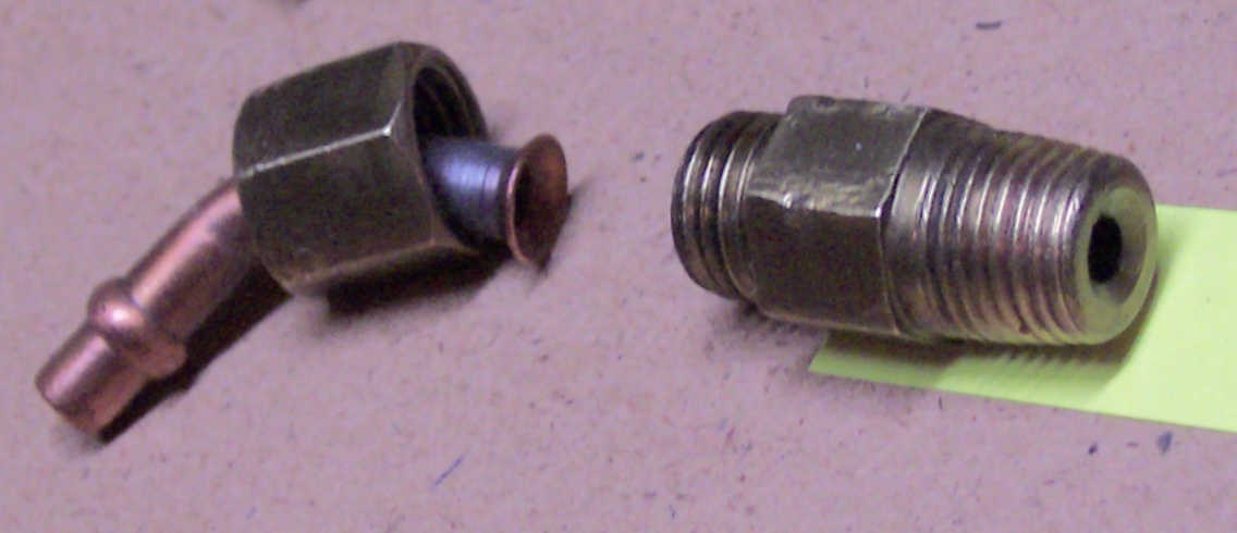 |
| Early model "two stage" brass pressure tap shown in upper left with pressure tube exiting side of tap and running to the fuel tank. Descending vertical pressure vent tube ends in front of the (non-standard Bendix) carburetor intake. | Single stage O-15-1 pressure tap showing brass ball and spring mechanism. | Late model single stage brass pressure tap. |
The ignition system of the O-15-1 as well as the O-15-3, O-45-1, and O-45-35 engines use an on-board, six volt battery-driven dual coil, triggered by the points and condenser, to fire both spark plugs at the same time. For the O-15-1, there was an additional, ground-based 6 volt battery booster system, wired in series, that could be plugged into the airframe for starting purposes.
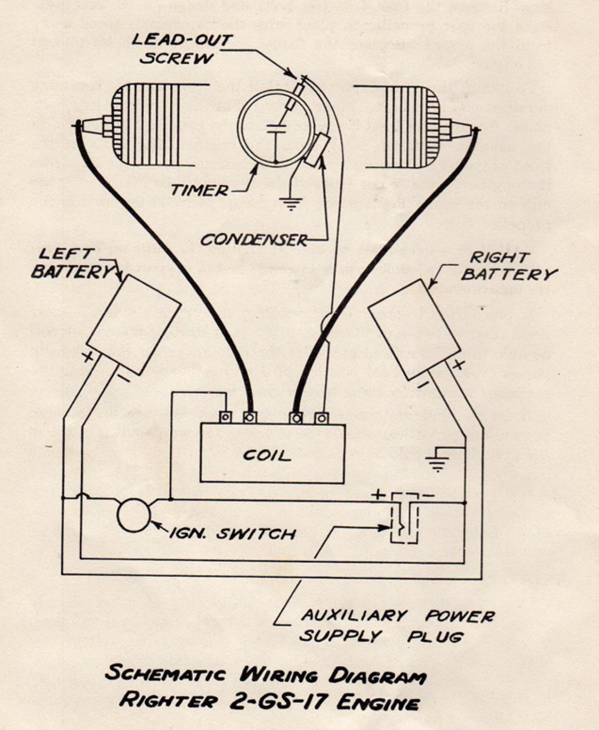 |
| 2-GS-17 / O-15-1 Engine Wiring Diagram. Note use of dual 6 volt dry cell batteries in parallel and the auxiliary supply jack to allow an additional 6 volt battery to be added in series to give 12 volts for starting. |
 |
| Propeller set for the O-15-1 engine The aft propeller (bottom) used a circular cork gasket between the forward face of the propeller and the flange plate, presumably to dampen vibration of the aft propeller assembly. |
The steel propeller hub for the fore prop mates to the 15° crankshaft taper and is held in place with an AN365-428 elastic stop nut. The steel hub for the aft propeller is a built-up assembly bolted to the gear case.
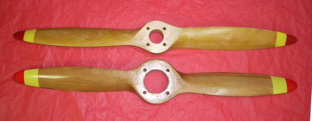
The contra-rotating propellers were 26" in diameter and were carved from solid or dual laminations of maple, cherry, birch, or beech wood by Story, Kroehler, Karpen, Flo-Torque, Ritz, and likely US Propeller Company. Not all original propellers had manufacturers' decals, but all were stamped with part numbers "10552" (fore) and "10552-1" (aft) in black ink on the side of the hub. The fore prop bore is 1.25" with 4" diameter bolt hole circle. The aft prop has a 2.0" bore and 5.5" bolt circle. The fore prop weighs 10.3 ounces and the aft prop 11.5 ounces.
The fore prop had a 21.7° pitch angle (equivalent to 24.4" pitch) at 75% diameter, while the aft prop had a 21.6° pitch angle (equivalent to 24.3" pitch). The original Radioplane drawings state the propeller(s) "approximates 23 inch pitch". A 1/8" inch thick cork gasket resides in the forward bore of the aft propeller to seal the fore propeller shaft as it exits the aft hub, preventing gear case oil from contaminating the friction surfaces of the aft propeller-aft hub interface.
2-GS-17 Type Test
Astoundingly, the US military required the low horsepower, non-man carrying, essentially disposable Righter and Herkimer 2-GS-17 engines to each pass a 50 hour type test at full-throttle 4,200 rpm, during war time!
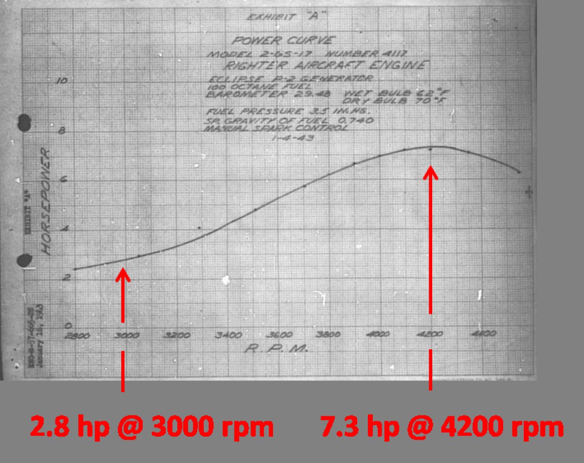
The results of the Righter 2-GS-17 type test were reported on March 3, 1943. The completion of the test had been delayed, and the purchase contract put on hold, due to failed connecting rod bearing caps after 13 hours run time in December of 1942. The test was completed using newly-designed rods. The engine produced 2.8 hp @ 3,000 rpm and 7 hp at 4,000 rpm (which is the rpm achieved in flight), and 7.3 hp at 4,200 rpm using 30° advance, indicating the engine probably used the timer with manual spark advance. As a result of the test, 14 recommendations were made including the use of through-bolts for the bearing caps, a reduction of fuel-oil ratio from 5 to 1 SAE 30 oil to 8 to 1 SAE 20 oil to reduce "carboning of the exhaust ports", a more secure spark plug insert, adjustment of the pressure tap to open at 0.5 psi with the elimination of the atmospheric vent, and strengthening of various hardware components. Later versions of the engine appear to incorporate many, if not all, of these modifications. It is interesting to note that the Righter 2-GS-17 / O-15-1 engines were produced, purchased, and utilized before the type test had been completed, likely due to the exigencies of war time.
 |
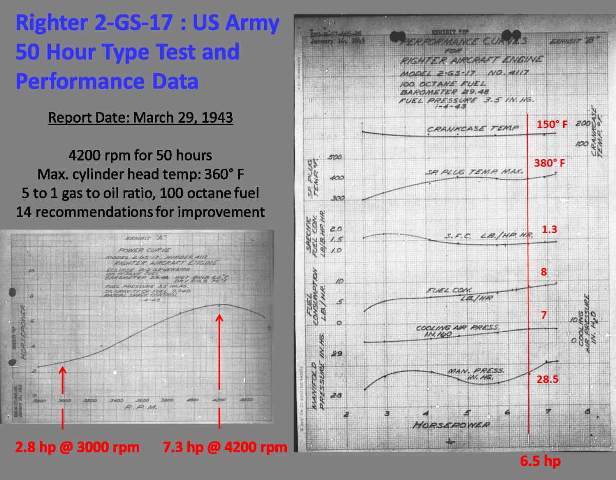 |
| Righter 2-GS-17 horsepower versus rpm curve taken from the Righter 2-GS-17 50 Hour Type Test run in January1943. | Performance curves taken from the Righter 2-GS-17 50 Hour Type Test run in January 1943. At 6.5 horsepower, the crankcase temperature was 150°F, spark plug temp. 380°F, specific fuel consumption 1.3 lb/hp/hr, fuel consumption 8 pounds per hour, using a cooling air pressure of 7" of water, and manifold pressure of 28.5 inHgA. |
The Herkimer 2-GS-17 completed its 50 hour type test as reported on July 8, 1943. On test, the engine produced 6.6 hp at 3,800 rpm. It is likely this engine had a centrifugal timer limited to 20° advance. The test ran a 5 to 1 SAE 30 oil fuel to oil ratio, but "carboning of the cylinder head required changing the spark plugs every 15 hours." The Army also detected a fault in the crankcase casting pattern that resulted in a partial blockage of the starboard transfer port. It was subsequently recommended that the Herkimer 2-GS-17 use a 10 to 1 SAE 40 ratio and correction of the crankcase pattern. The report listed 14 Herkimer-instituted engineering changes to the Righter 2-GS-17 design to improve the engine, simplify its manufacture, or reduce costs. Specifically noted in the report was that none of the engineering changes made by Herkimer affected the interchangeability of Righter and Herkimer parts in the 2-GS-17.
The O-15-1 cylinders (and as we'll see, the O-15-3 cylinders as well) were built with both rectangular and round hole port configurations. Both port geometries shared the same height differential between exhaust and transfer ports and thus identical port timing. Remarkably, the rectangular ports have 53% more area than the round port cylinders, yet the cylinders were interchangeable and performance is assumed to be comparable. This indicates that transfer and exhaust port area was not a limiting factor in the design and performance of these engines.
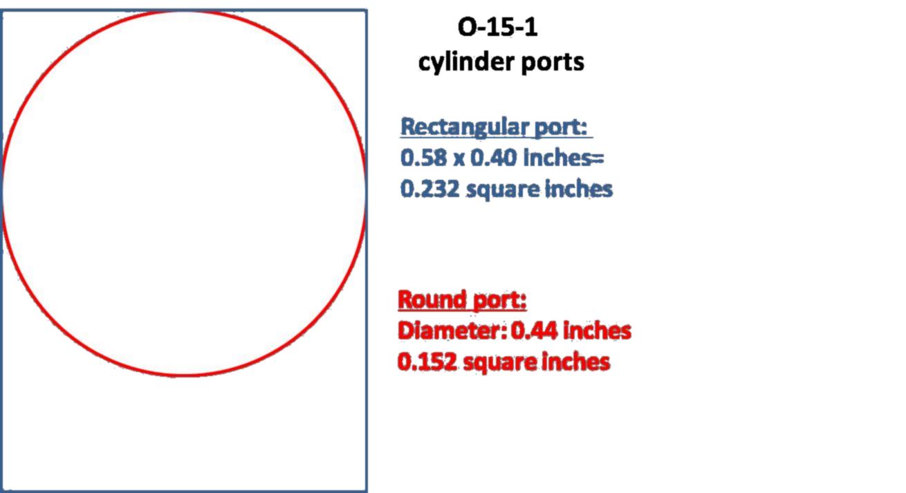 |
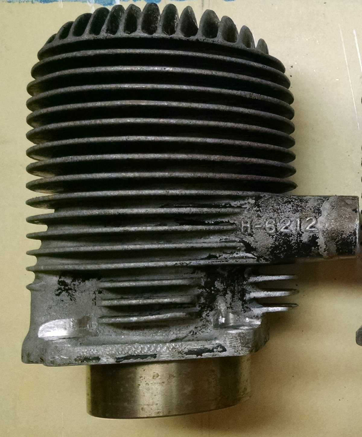 |
| Scale area comparison of the rectangular port versus round port O-15-1 cylinders showing the 53% larger area of the rectangular port configuration. | Herkimer 2-GS-17 Cylinder Part Number H-6212. This cylinder has round ports. |
The limited number (8) and unavailability of surviving Herkimer 2-GS-17 engines, and the fact that Herkimer did not stamp their data plates with date of manufacture, did not allow me to asses if the type-test recommendations were implemented. Also, the functional interchangeability of Herkimer and Righter parts allows for engines to be built up of mixed Righter and Herkimer parts during and after the war. However, examination of a few engines reveals some Herkimer parts had "H" as a prefix, such "H-6212" on the cylinder and "H6227" on the rotary valves while the majority of Righter engines have "6212" cylinders and "6227" rotary valves. Of the three Herkimer 2-GS-17 engines I have been able to examine, H-6212 cylinders can have either round or rectangular cylinder ports, and I have yet to find a Herkimer 2-GS-17 without a centrifugal – type timer.
The 50 hour type test was performed using Herkimer 2-GS-17 serial number H-1, the lowest known surviving Herkimer serial number is H-126, and the highest surviving serial number is H-1249.
AEHS member Ted Koch has been cataloging the surviving WWII drone engines for several years, and there are approximately 25 Righter 2-GS-17 engines in his compendium, with several more known to exist but not identified, missing the data plate, or with unreadable data plates. However, many of the listed engines have serial numbers as well as the month and year of manufacture, which allows a rough estimate of production to be made. From April 1943 to June 1943, at least 898 model 2-GS-17 engines were produced by Righter; roughly 18 engines per day during a 6 day work week. The lowest known surviving Righter 2-GS-17 serial number is 41-01 and the highest 42-3558.
- On to Part 3. The Righter O-15-3 Engine -
Send mail to
![]() with questions or comments about this web site.
with questions or comments about this web site.
![]()