WWII Gunnery Target Engine Technical Analysis
Part 1. Background and General Configuration
by Tom Fey
Published 19 Jun 2017
|
If you were to power a 120 pound, radio-controlled, disposable target aircraft in the late 1930s, what type of engine would you choose? This was the challenge faced by Remotely Piloted Air Vehicle visionary Reginald Denny and his engine designer, Walter H. Righter, as they sought to provide the US military with a cost-effective gunnery training system in the years leading up to WWII. Righter chose the air cooled, two cylinder, horizontally opposed, two-stroke configuration to propel the nearly 15,000 Radioplane drones produced during WWII. With contra-rotating propellers, the first production engine drove the sub-scale RP-4 drone to 70 mph in 1939, culminating with 35 pound, 35 horsepower units driving prototypes to 190 mph by March of 1945. The technical evolution of the 0-15 and 0-45 series of obscure, workmanlike powerplants is described in detail by AEHS member and drone engine restorer Tom Fey. |
Contents
Part 1. Background and General Configuration
Part 2. The Righter 2-GS-17 (O-15-1) in Detail
Part 3. The Righter O-15-3 Engine
Part 4. Performance and Efficiency Comparison between O-15-1 and O-15-3 Engines
Part 5. The O-45-1 and Kiekhaefer O-45-35
Part 6. Performance and Efficiency Comparison between O-45-1 and O-45-35 Engines
Part 7. Conclusion
Introduction
On May 4, 1939, after two years of development, and five months before the outbreak of WWII on September 1, 1939, the US Army Air Corps accepted the first three unmanned, sub-scale, radio controlled aerial gunnery targets from what would become the Radioplane Company in Van Nuys, California. The history of the drones and the men that developed them, Reginald Denny, Walter Righter, Kenneth Case, and Paul Whittier makes interesting reading:
http://www.ctie.monash.edu.au/hargrave/denny.html and Fifty Years of Target Drone Aircraft, by Richard A. Botzum.
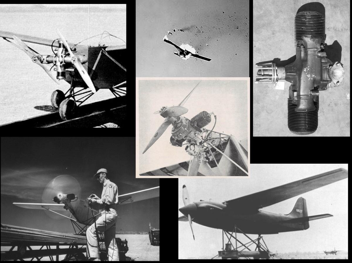
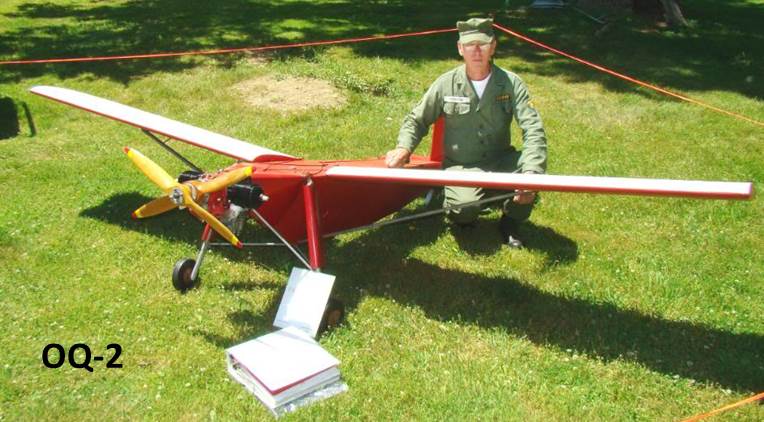
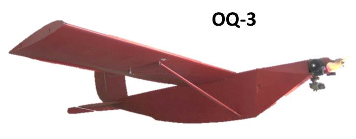
The Radioplane gunnery targets used during WWII were designated OQ-2, OQ-3, and OQ-14 for the US Army (TDD-1, TDD-2, and TDD-3 for the US Navy). The dimensional specifics of these drones can be found in the tables, but in general, these were catapult-launched, fabric-covered aircraft of welded steel tube construction with wingspans around 12 feet, weighed 97 to 134 pounds, and were guided by rudder and elevator control. They were powered by unthrottled, two-cylinder, two-stroke engines of 6.5 to 22 horsepower, flew wide open for up to one hour guided by line-of-sight radio-control, and could be recovered for reuse by a self-contained parachute system. Records indicate 14,981 of these drones were produced in WWII at a cost ranging from $300 to $750 per unit.
 |
 |
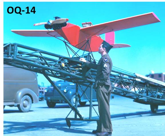 |
| Restored Radioplane OQ-2 Aerial Gunnery Target Powered by the Righter O-15-1 Engine | Radioplane OQ-3 Aerial Gunnery Target Powered by the Righter O-15-3 Engine | Radioplane OQ-14 Aerial Gunnery Target Powered by the Righter O-45-1 Engine |
My interest in this topic began with the 1999 discovery of a 1943 Righter 2-GS-17 (military designation is O-15-1) engine that had counter-rotating propellers, in the Pioneer Museum in Murdo, South Dakota. Thirteen vigilant years later I purchased a tired, semi-complete O-15-1 carcass out of a museum and restored it to running condition. When I learned that there was a series of Righter-designed engines of increasing horsepower that powered the wartime drones, it became my quest to obtain and restore one of each type to running condition. This in turn led to the following question:
As I pondered the above question, my ongoing restoration of a 1945 Righter-designed, Kiekhaefer-built O-45-1 engine (45 in³ = 747 cc; 22 horsepower @ 4,000 rpm) led me to another Kiekhaefer engine, the O-45-35. This engine ran in March 1945 but missed production before war end, and churned out an astounding 35 horsepower at 4,250 rpm! So question #2 became:
These questions, my burgeoning interest in the technology of the times, and a YouTube video I posted of the 2-GS-17 / O-15-1 running, led me to the community known as "drone heads." This group of engine collectors, in particular fellow AEHS member Ted Koch and Minnesota-based Kevin Russen, plus a widening group of a dozen others, helped answer my questions regarding restoration, parts, and history. Even more importantly to this present work, they disassembled, measured, and photographed their engines to allow me a chance to do justice to this unique topic. I am extremely grateful for their generosity, cooperation, and patience in this endeavor.
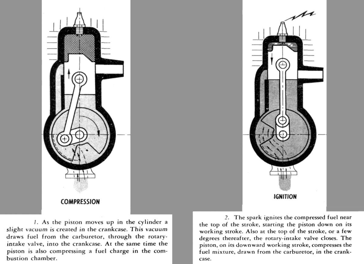
Before discussing the engines in detail, I think it appropriate to describe the operating cycle of this particular two-stroke engine design. Below please find the text and diagrams describing the operating cycle lifted directly from the manual:
 |
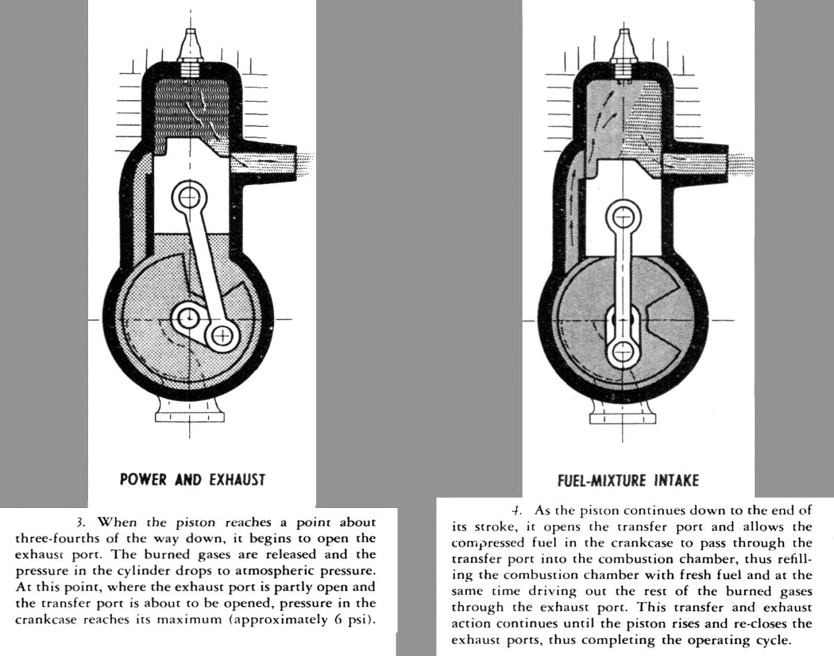 |
| Description of the operating cycle of the two-stroke engine from the Handbook of Instructions with Parts Catalog Radio-Controlled Airplane Target AAF OQ-3 Navy Model TDD-2, AN 28-10C-2, 25 September 1944. | |
The Righter Sidewinder
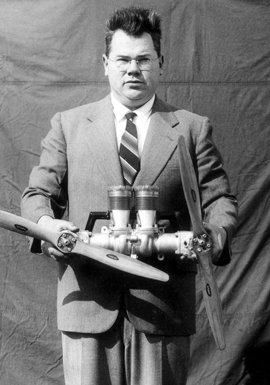
The power plant for the first 53 drones purchased by the US Army Air Corps was a remarkable twin cylinder, dual output, counter-rotating propeller engine known as "The Sidewinder." Because of the slow response time of the period electronics, rudder-only control, and the torque of the engine trying to twist the airplane into the ground at the relatively takeoff low airspeeds, dual-rotation propellers became the answer to overcoming these challenges. The first iteration of the dual rotation engine utilized a dual-output crankshaft that was connected to opposing extension shafts that drove bevel gears that placed the prop shafts in a plane 90° to the crankshaft. The prop shafts rotated in opposite directions and the propellers were locked in phase 90° to each other. The engine displaced 10.2 in³ (167 cc), produced 4 to 6.5 horsepower, and used propellers 24" in diameter. Righter produced two versions of the Sidewinder: propellers rotating outwards at the top, or propeller rotating inwards at the top. The latter version was the ultimate choice, and unfortunately, none of these Sidewinder engines are known to survive.
 |
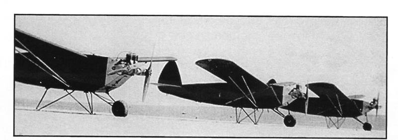 |
| The Righter Sidewinder engine with phased, 24" diameter propellers held by designer/builder Walter H. Righter. | The first three RP-5 Aerial Gunnery Targets were powered by the Righter Sidewinder engine and accepted by the US Army, May 4,1939. |
General Configuration of the Righter-Designed WWII Drone Engines
The Righter engines are horizontally-opposed, two cylinder, simultaneously-firing, loop scavenged two-stroke engines with rotary valve induction. The crankcase is an alloy casting with a robust ball bearing in the forward face to support the crankshaft and take the thrust loads of the tractor propeller. In some cases the nose has a needle bearing as well as the ball bearing. The cylinders are 180° opposed with a two-throw steel crankshaft unsupported in the middle. The power section of the engine is an alloy casting that houses the intake trunk for the carburetor and bearing(s) for the tail of the crankshaft. The forward face of the rear crankcase cover is machined smooth to mate with the cast iron rotary induction valve driven by the crankshaft. The ignition system, known as a "timer" is bolted to the aft end of the rear cover, and the tail of the crankshaft acts as a cam to open the ignition points.
The use of a rotary induction valve is typical of the times. Materials to build reed-type induction valves that would not fatigue, fracture, and destroy by ingestion were unavailable in the 1940s. Rotary valve induction is more precise and tunable to a specific rpm range than a reed system because the latter has to deal with both reed inertia and differential pressures to open and close. For an engine intended to run in a narrow rpm range, such as the drone engines running wide open all the time, rotary valves were the way to go.
The cylinders are sand or die cast aluminum with shrink fit cast iron cylinder liners, all secured to the crankcase by four studs. The intake transfer and exhaust ports are opposed by 180° and the single 18 mm spark plug is seated in either a bronze bushing or steel Heli-coil insert in the center of the head. The pistons are aluminum alloy and shaped for loop scavenging. The piston rings, connecting rods, and bearings vary between the four engines discussed herein.
Unique to the 2-GS-17 / O-15-1is a sealed gear case on the front of the engine used to achieve coaxial contra-rotation of the propeller shafts. The specifics of the various engine components will now be dealt with on an engine-by-engine basis.
- On to Part 2. The Righter 2-GS-17 (O-15-1) in Detail -
Send mail to
![]() with questions or comments about this web site.
with questions or comments about this web site.
![]()