Packard Builds the Rolls-Royce Merlin
Part 2: 17 Aug 1940 – 31 Dec 1940: Specifications, Accessories, Manufacturing/Test Plans
Compiled by Kimble D. McCutcheon
Published 11 Jul 2026
17 Aug 1940. PPL civilian employee T.B. Holliday authored a memorandum report on behalf of Maj C.M. Cummings, Air Corps Equipment Laboratory, confirming a 9 Aug 1940 conference with Packard's Col J.G. Vincent at the Materiel Division. Packard submitted preliminary mounting and driving arrange layouts for standard engine-driven generators and a modification to the R-R starter design to use Air Corps standard parts. The Packard-designed generator mount was not entirely satisfactory since mounting studs interfered with installation of the largest size generator and because the coupling did not fit the standard spline and did not provide bearing support. In view of the fact that generators were constructed for installation on a mount that conformed to Specification AN-9528 and that required concentricity that could only be provided with a bearing support, the coupling spline has taken advantage of this fact. As a result, certain generator designs had a floating drive member that necessitated the use of an accurately-aligned driving member. When this situation was explained to Vincent, it was agreed tat the mounting pad would be revised by moving the flange sufficiently to clear mounting studs. The coupling spline was also to be revised to provide bearing support.
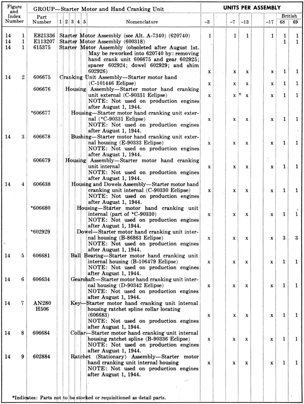
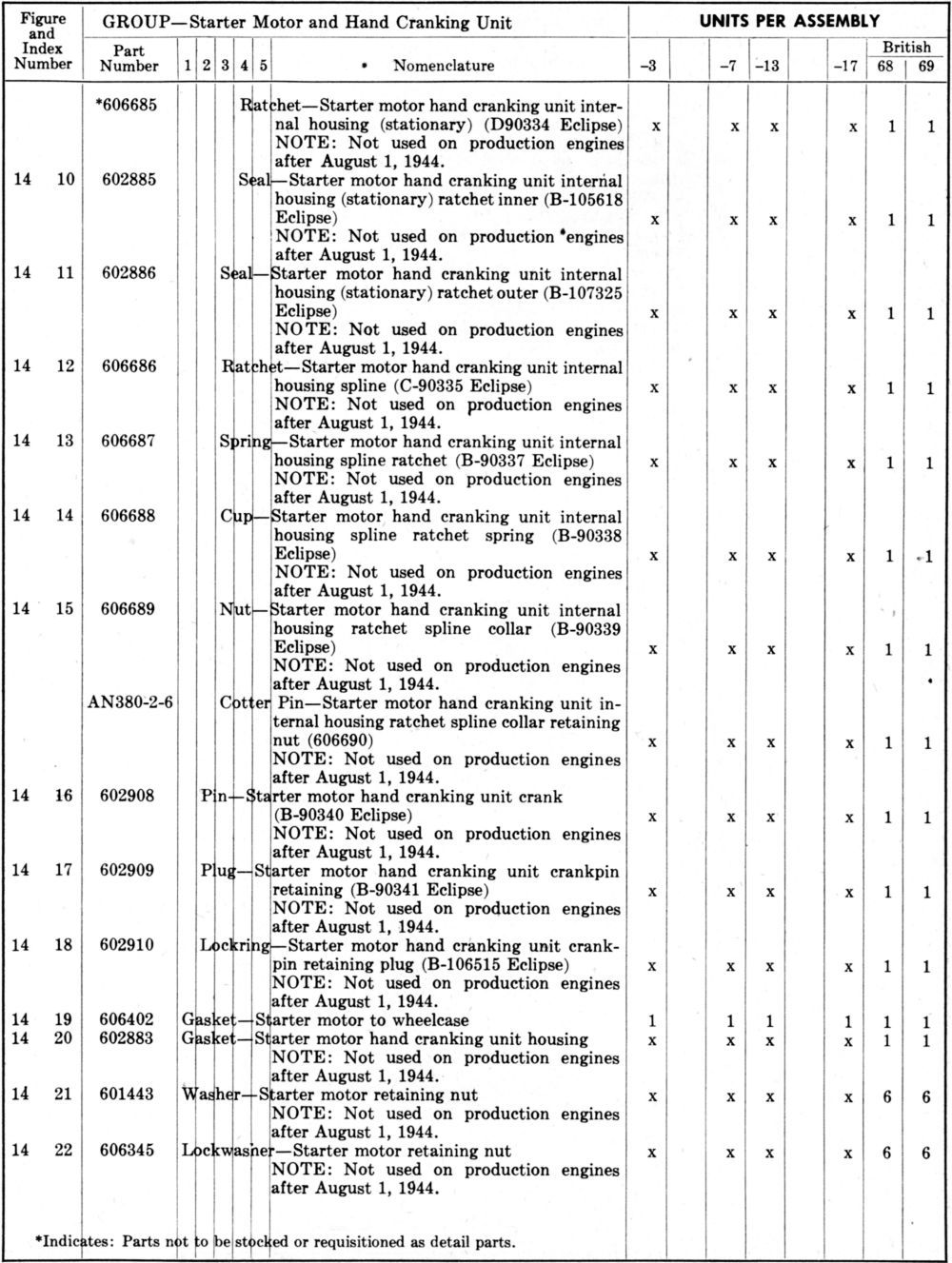
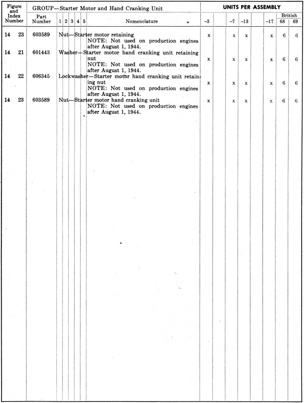
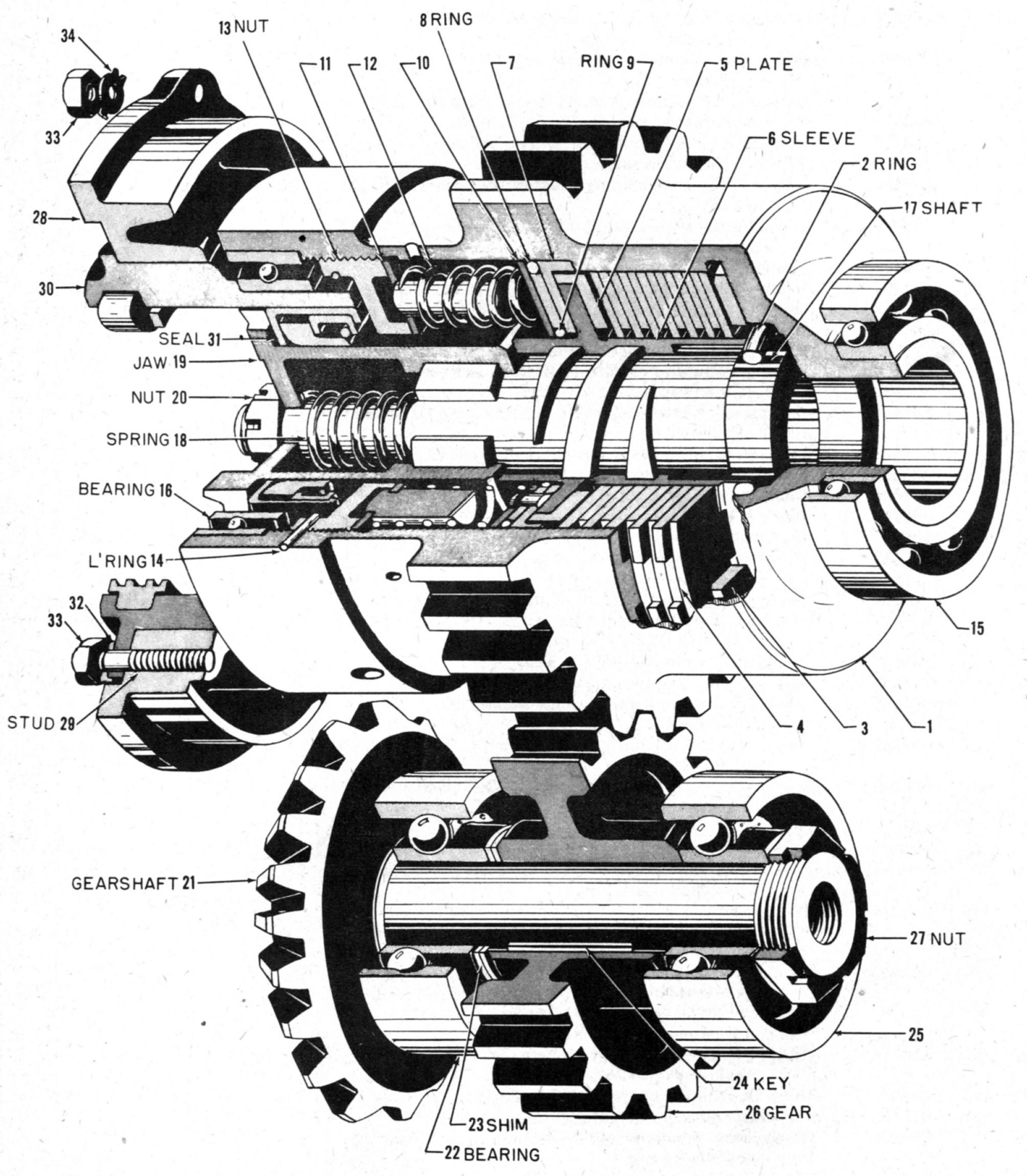
Packard's starter arrangement had been based on a layout by Eclipse Aviation that eliminated one planetary gear set and provided a standard clutch and spline. It was agreed that this layout was satisfactory. The Division requested that Packard substitute an AN connector for the shielded terminal shown on this layout. [Memorandum Report EXP-M-54-656-126. Generator and Starter Arrangements on Rolls-Royce Engines. 128 – 129.]
17 Aug 1940. Maj Carroll wrote the Curtiss Aeroplane Division of Curtiss-Wright with information concerning the proposed installation of the R-R Merlin engine in the Curtiss P-40D airplane.
1. Coolant System. The British coolant system installation differed from the Air Corps installation. The thermostatic valve was considered necessary by the British to avoid rapid temperature changes. The Air Corps has relied on the manual adjustment of radiator shutters to avoid the complication and problems associated with an automatic valve. In all other respects the Division thought the Air Corps system at least equal to if not better than the British system. This opinion was based on experience with American engine, but was thought applicable to the Merlin. It also strove to avoid the rather complicated automatic British valve. The Division recommended that two types of the first experimental installations be made; one according to the British practice and one according to Air Corps practice. Since a pressure system was contemplate on both installations, all test pressures were to be based on 50 psig, the radiator should be required to withstand 25,000 cycles from 0 – 50 psig applied to the radiator inlet with steam. (The P-40 radiators had passed this test.) In making an Air Corps installation, the use of centrifuge vapor separators were to be made a definite requirement rather than dependent upon the indications of its necessity.
In the British installation, the following items were to be complied with:
(a) The thermostatic bypass valve and expansion tank pressure regulating valve were to be furnished by the engine manufacturer since the engine required them.
(b) The British requirement for radiator flow characteristics must be followed carefully; the British expansion tank makes the pump inlet pressure below the header tank pressure by the extent of the radiator pressure drop.
(c) Thermostatic bypass valve use subjected the radiator to freezing at altitude if the contemplated glycol coolant mixture was used; it would be necessary to provide a radiator thermal jacket. This was shown in some of the British installation information. Inasmuch as American winter temperatures were much colder than British temperatures, the use of this jacketed radiator was to be required when the thermostatic valve bypass valve was used.
With either installation the Air Corps standard cooling requirements were applicable.
2. Oil System. Air Corps recommended that the standard Air Corps oil tank and hopper system be used. The use of oil filters or oil strainers in the oil line between the tank and the oil pump inlet were not considered good practice and were not desirable. Air Corps standard oil cooling requirements as set forth in Specification No. 28187 were to apply except that maximum oil inlet temperature was not to exceed 90°C. Oil line sizes were to conform to the Air Corps Handbook unless size specified by R-R was larger, in which case the larger size should be used. All pipe threads, oil pipes and oil connections were to conform to Air Corps Handbook requirements and Air Corps material requirements. The oil inlet thermometer was to be installed in accordance with Handbook requirements, not in the engine; Air Corps standard instruments were to be installed.
3. Fuel System. Air Corps recommended that the fuel system then in use on P-40 airplanes be used with the addition of fuel system cooling provisions. [Letter, Maj Carroll to Curtiss-Wright Airplane Division. 130 - 132]
17 Aug 1940. Maurice Olley wrote George Mead suggesting a greatly increased salary for Dr. Lessells. He was being paid $250 per month out of the Rolls-Royce American office for his part-time consulting work on the R-R wartime engine job. Olley thought his work indispensable to the project and thought it would be necessary to "conscript" his services full time, which would reqire a salary of at least $15,000 per year. Olley included expenses chargeable to the American Merlin Job:
| Item | Description | Cost/Month |
|---|
| (A) | Office 2-221, GM Bldg., Total operating costs | $750.00 |
| | Offices 2-250 & 2-251, GM Bldg., Cost chargeable to the Merlin Job | $2,500.00 |
| | Procurement of sample parts for test either in England or at Wright Field (this item could be eliminated if Packard purchased these samples) | $7,000.00 |
| | Total, First Three Months | $10,250.00 |
| | Total, Each Additional Month | $3,250.00 |
| (B) | Salaries of 3 key men now charged to British Supply Board | $2,255.00 |
| | 50% Olley's salary (now charged to R-R Ltd | $500.00 |
| | Key men travel expense ($300 per month each) | $1,200.00 |
| | Total | $3,955.00 |
Item (B) was not to be assumed by the American Merlin contract without notification of the British Supply Board and readjustment of salaries on the basis of American Standards (as verbally arranged by Knudsen). The following schedules covered expanses chargeable to the American Merlin job that were already incurred as of 9 Aug 1940:
| Item | Description | Cost |
|---|
| Schedule (A) | Distribution of expenses for July 1940 | $1,715.75 |
| Schedule (B) | Cost of setting up office 2-221 | $656.36 |
| | Total chargeable American Merlin as of 9 Aug 1940 | $2,372.11 |
[Letter, Olley to George Mead. 133 – 135.]
19 Aug 1940. Vincent wrote Col Echols explaining that Packard was contemplating provided carburetor air heating and cooling to maintain temperatures at the carburetor in the 70°F – 90°F range; the cooling was to reduce maximum summer air temperatures and the heating was to raise the air temperature to a minimum during winter. Both initial and operating costs were high. In a conference with Rees from R-R, it emerged that such carburetor air conditioning for liquid-cooled engines was not necessary; test results obtained at any time of the year could be corrected to standard temperature and pressure. Vincent wanted to ascertain that this convention had not been dictated by the Air Corps at some point. [Letter, Vincent to Col Echols. 136. NOTE: All correspondence to the Materiel Division, Wright Field, was addressed to the Assistant Chief, Materiel Division, who was Col Echols at the time. This was done so that Col Echols remained cognizant of project developments. From the Office of the Assistant Chief, the correspondence was then routed to the specific officer/employee who was the expert for that subject.]
20 Aug 1940. During a telephone conversation between Chenoweth and Vincent where Packard's 15 August letter concerning accessories and their mounting provisions was discussed, Chenoweth relayed the Division's positions on the accessory and mount drawings:
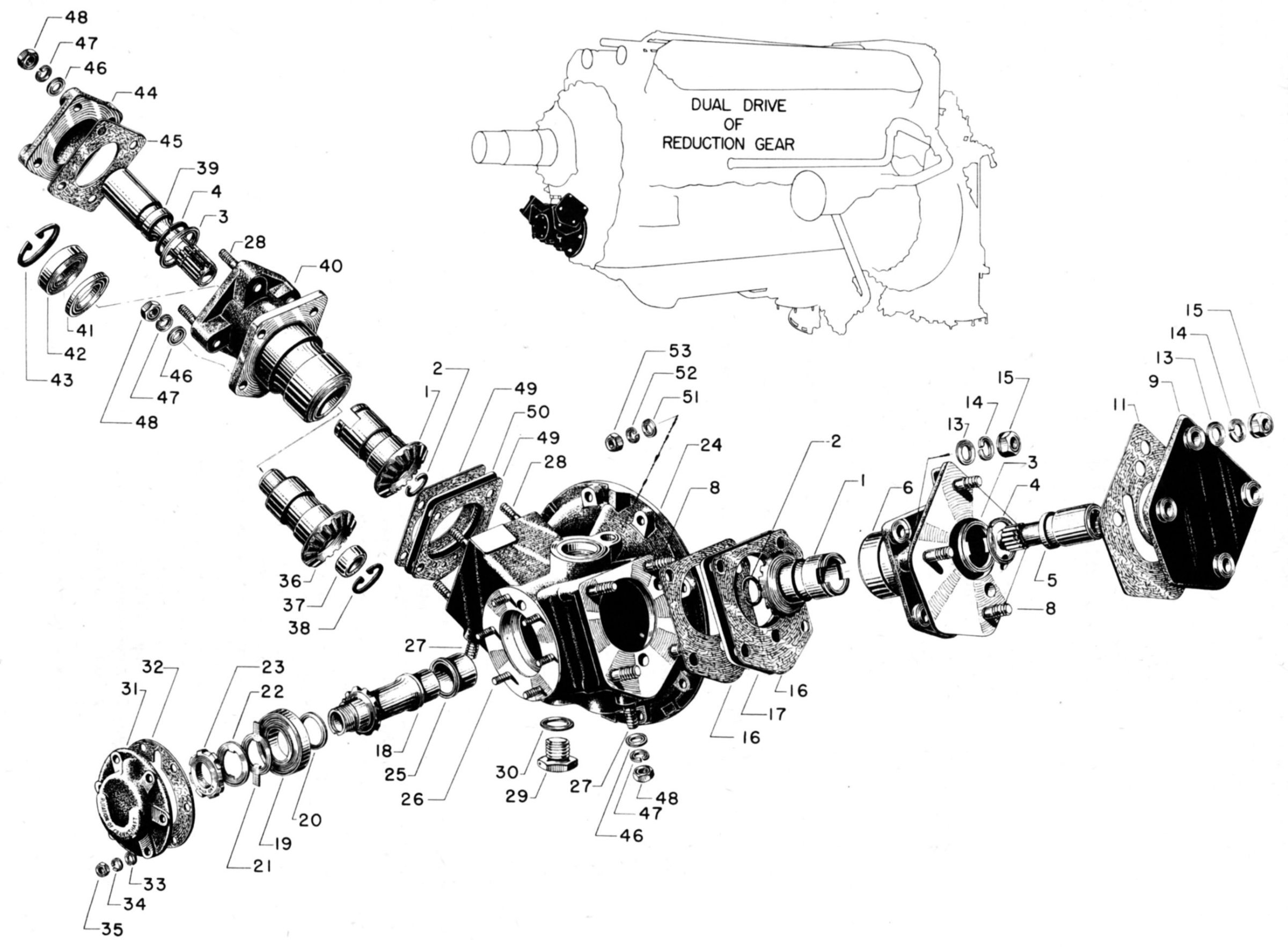
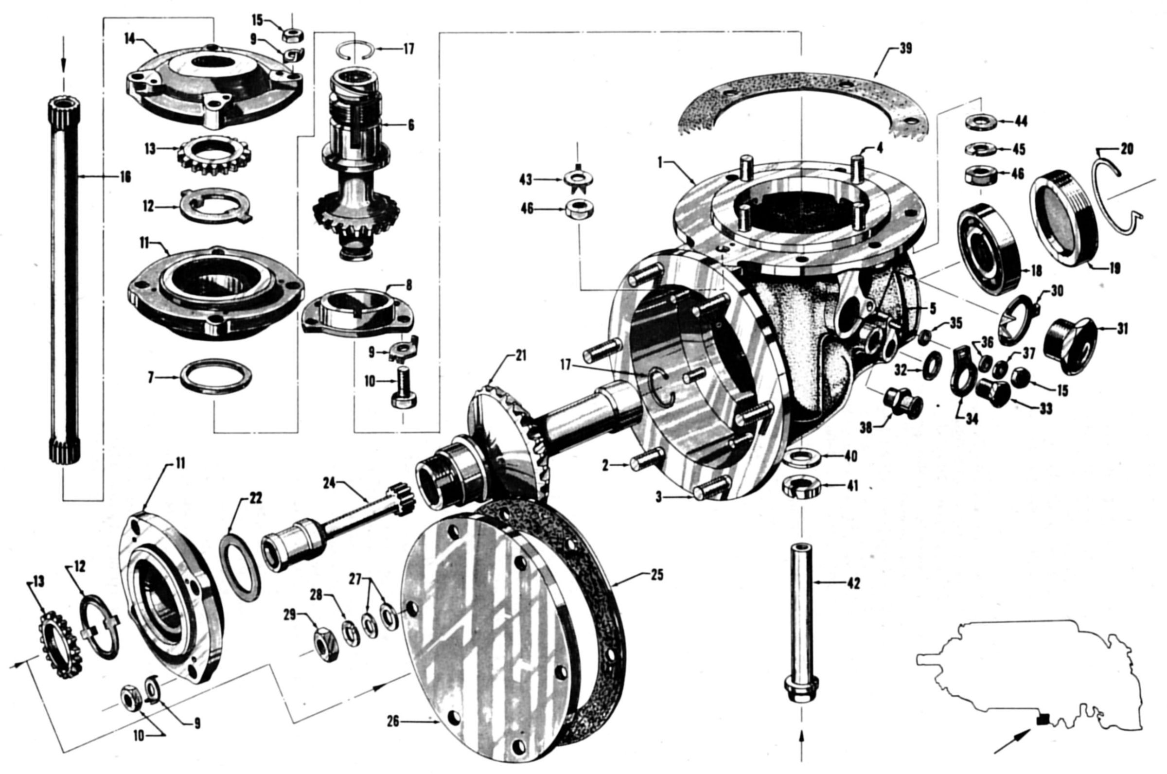
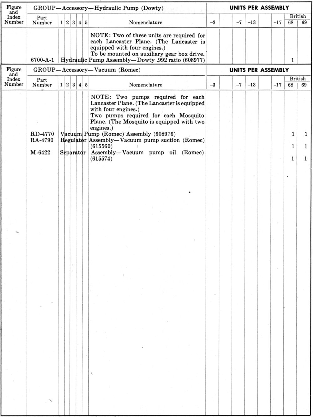
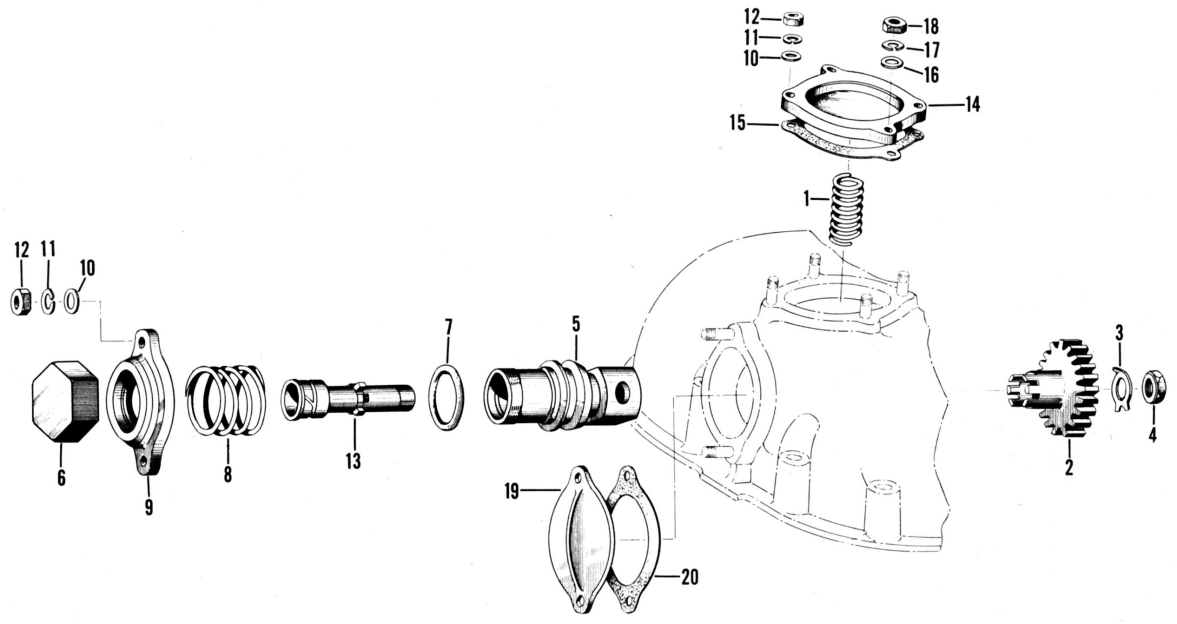
PM-100 – Propeller Shaft, Governor and Vacuum Pump. The propeller end drawing was satisfactory. Vincent related that during meetings with both Curtiss and Hamilton Standard engineering representatives a compromise governor drive arrangement had been developed. Vincent promised to send drawings to the Division. Vincent stated that the vacuum pump installation had been altered to provide for the standard Air Corps drive.
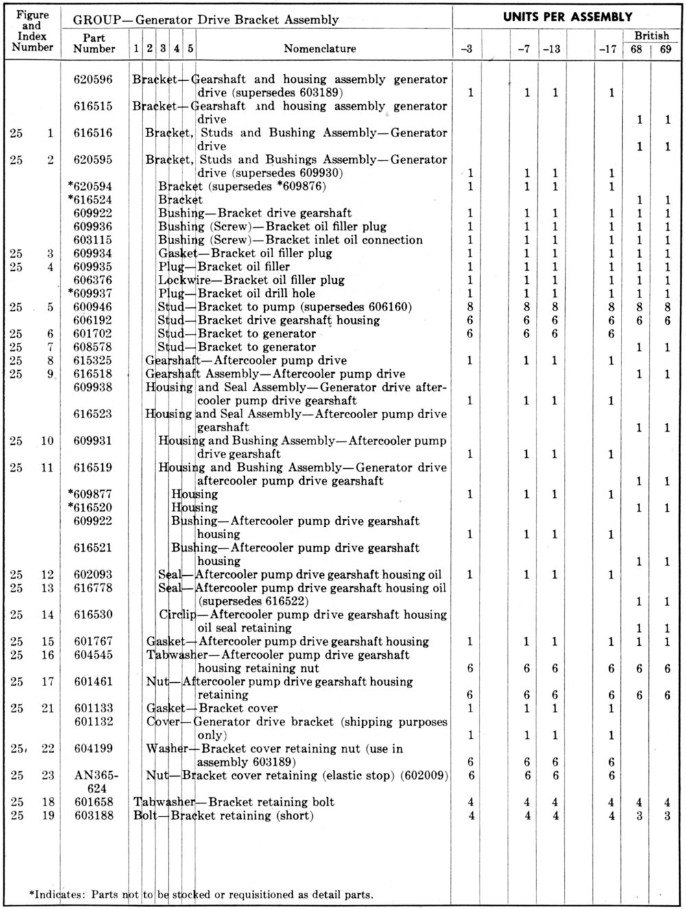
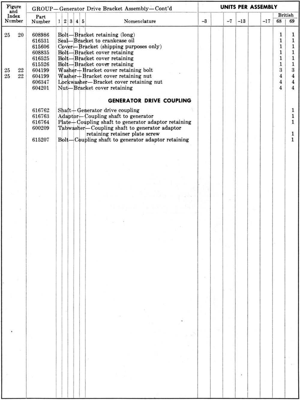
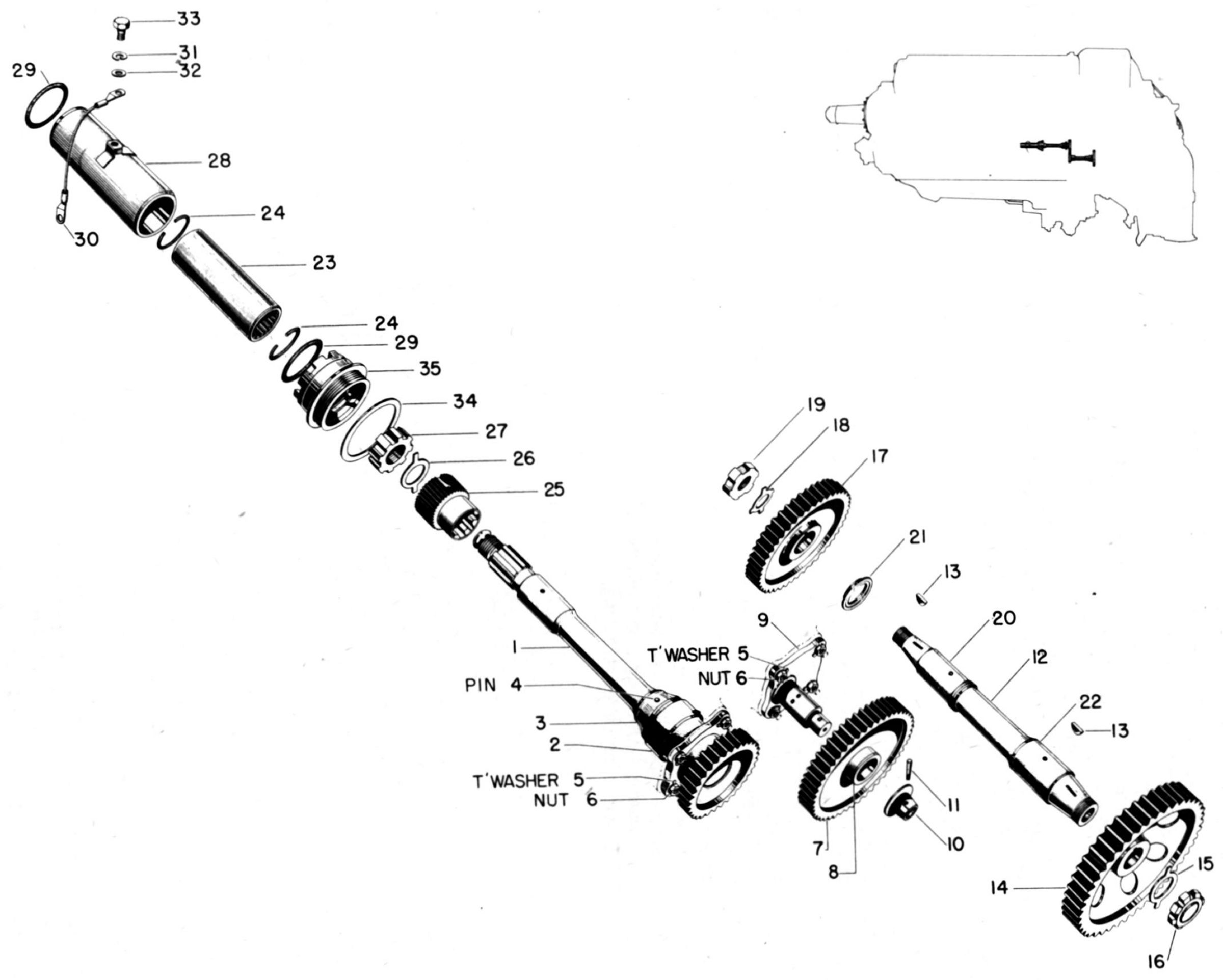
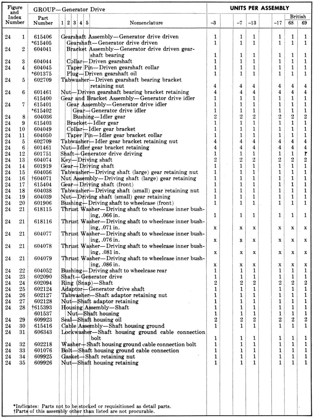
PM-101 – Generator Drive. Although the Division thought the drive was satisfactory, Vincent was making a new sketch showing an improved arrangement for the external drive shaft tube; he planned to submit a copy for the Division's consideration. This new arrangement allowed removal of the entire adapter and installation of another adapter that would take a British generator.
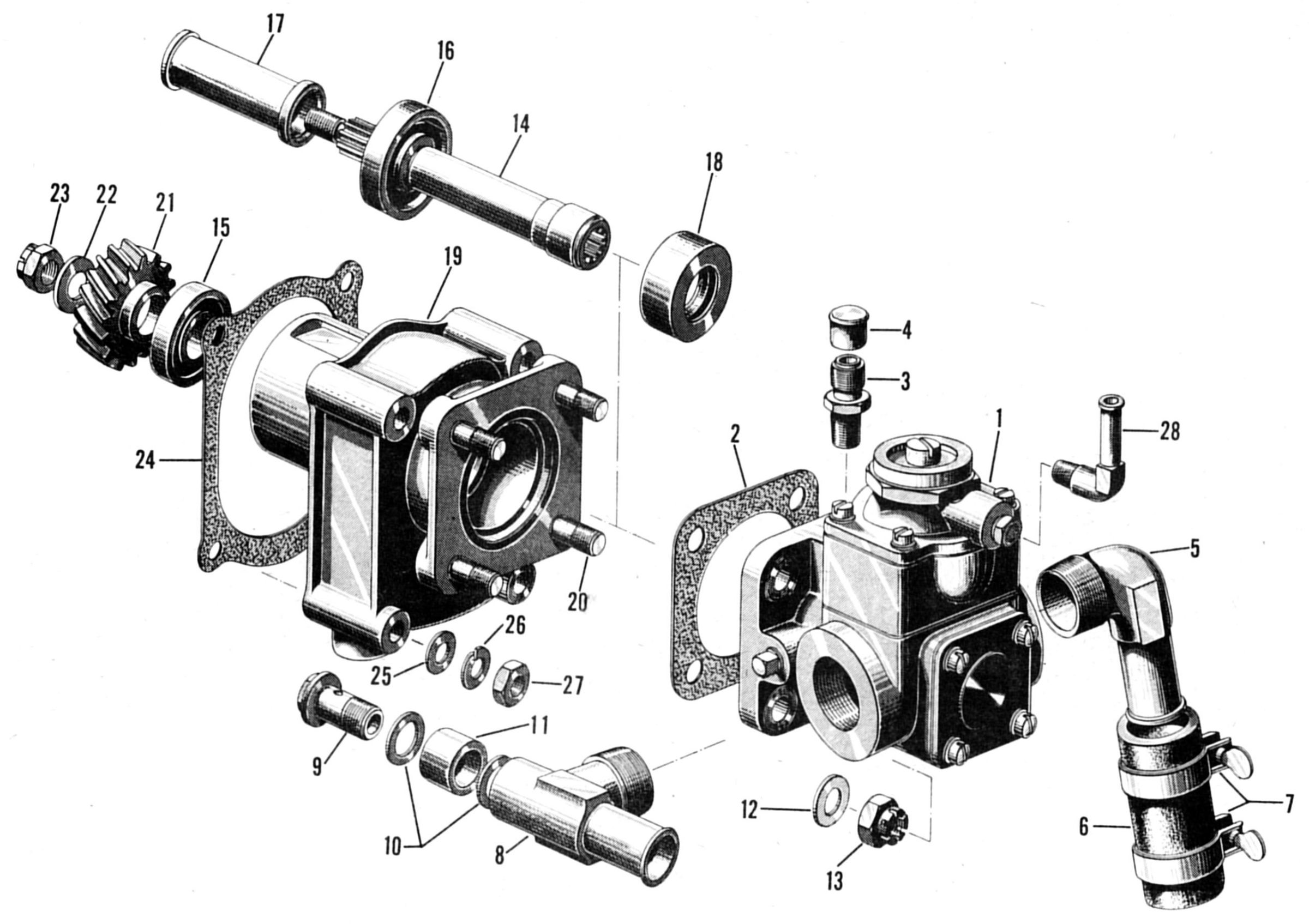
PM-102 – Fuel Pump Drive. This was satisfactory.
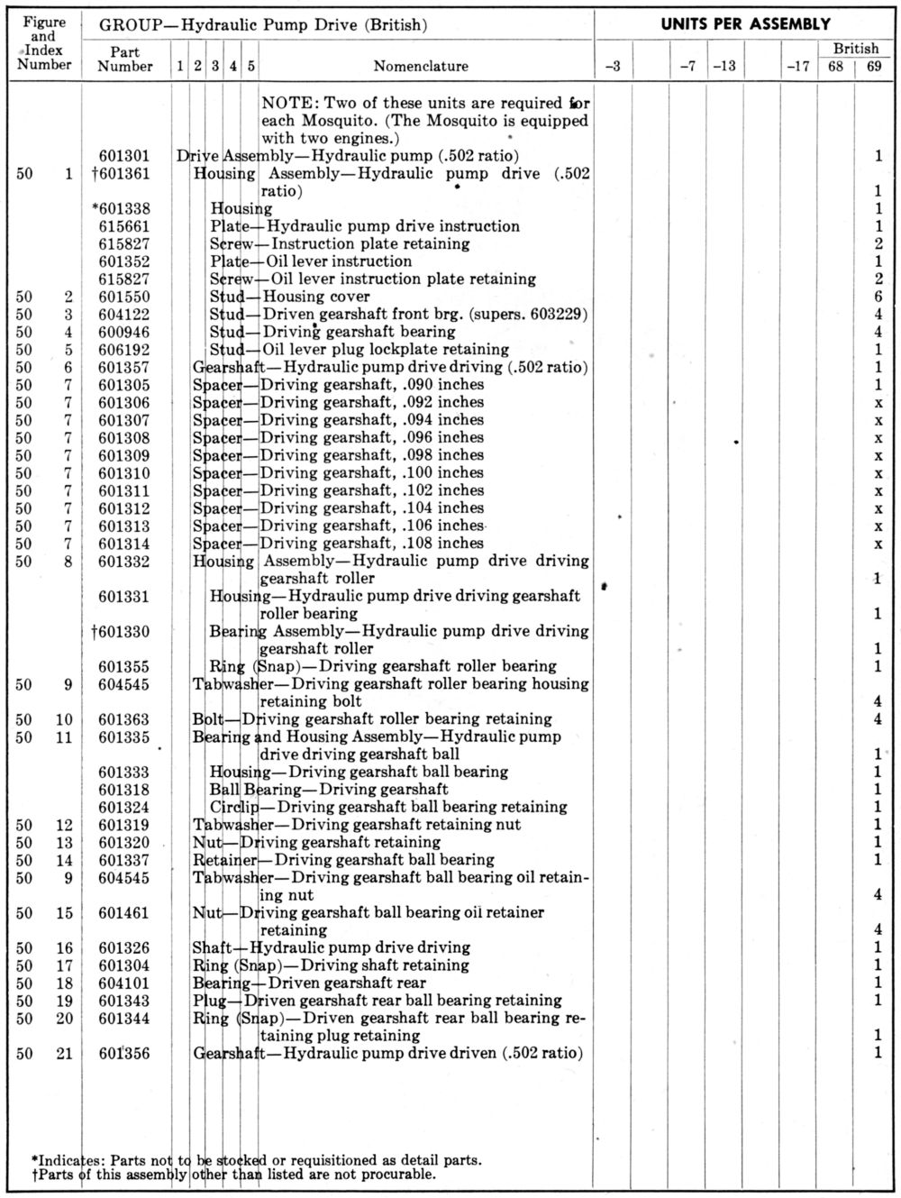
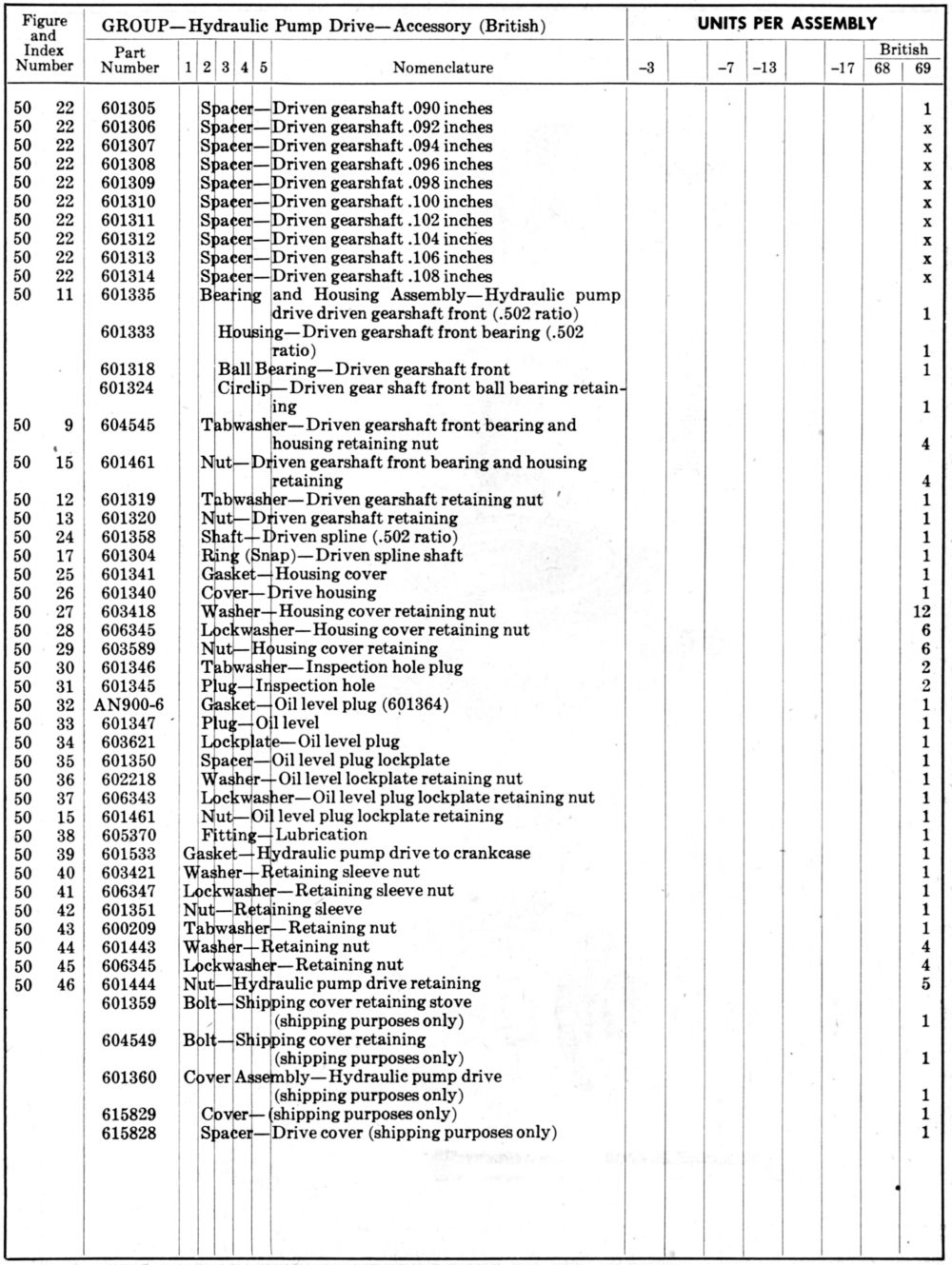
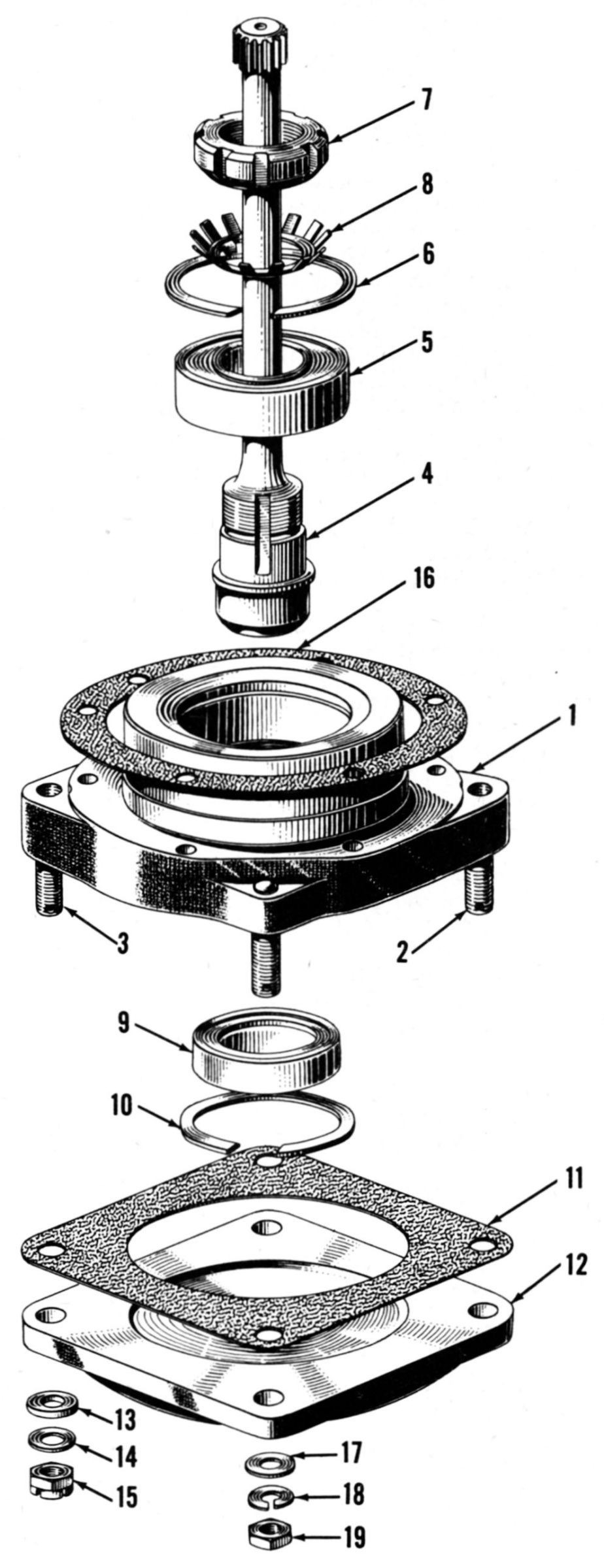
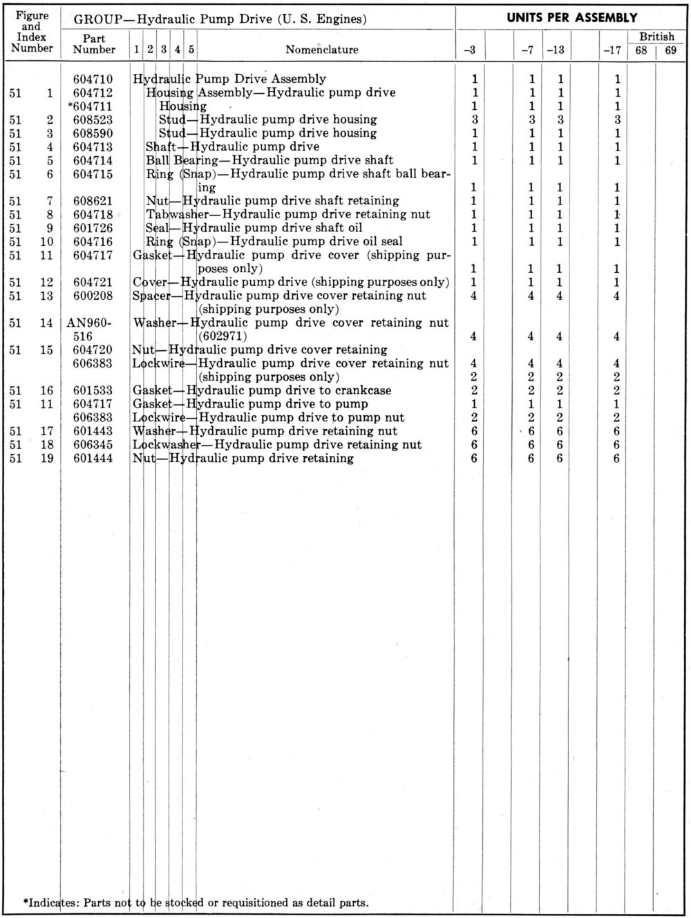
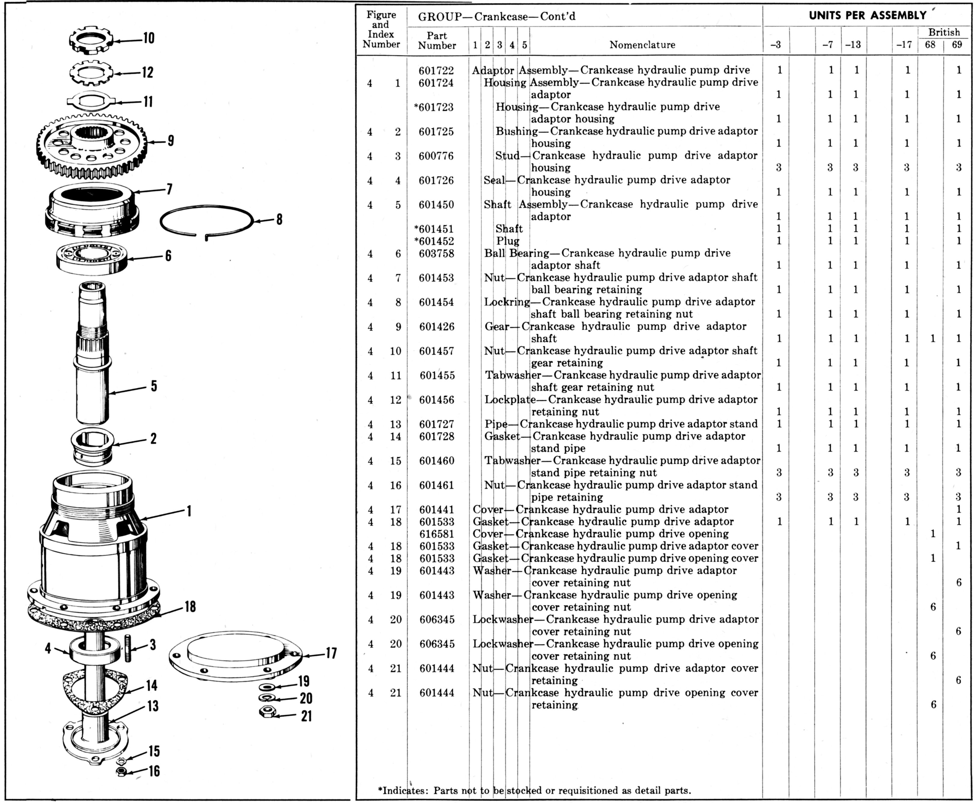
PM-103 – Hydraulic Pump Drive. The ratio resulted in the pump being driven at 2,903 rpm at normal engine speed, which was about 60 rpm below the minimum desired. Vincent agreed to investigate whether the ratio could be increased but was also told that the existing ratio was satisfactory if the increase were impossible. The adapter flange and bushings as per Specification AN-9521 were missing from the drawing. The latest specification revision gave a chordal slot width at the 0.0781 pitch diameter instead of the 0.0799 that was shown.
PM-104 – Gun Synchronizer. Vincent was unclear as to how lubrication was to be provided and requested that an Armament Laboratory representative telephone him.
Vincent opined that it was now time to remove the prefixes "experimental" and "preliminary"; Chenoweth agreed, but reminded Vincent that all specification revisions were to apply a new suffix letter and the date on which the specification was released.
¶ C-1. Material. Satisfactory.
¶ E-17a. Spark Plugs. Packard proposed to add a phrase so the requirements would read: "The Rolls-Royce spark plug threaded bushings are to be duplicated and the engine is to be equipped with 14mm spark plugs that will be interchangeable in Rolls-Royce built engines, of a type to be approved by the Government." He stated that this was an important change, particularly to the British because it meant that spark plugs could be used interchangeably in all Merlin engines. When asked if this in any way prevented the use of American spark plugs, Vincent stated it did not, provided they used the same method of cylinder installation and shielding attachment.
¶ E-26a. Starter. Satisfactory.
¶ j. A copy of a sketch showing substantially the same dimensions as the BG 14mm plug would be submitted inasmuch as Ellor had asked for standard atmosphere conditions, a copy of NACA Report #218 would be forwarded.
¶ k. Vincent asked about carburetor temperature limits required for acceptance testing and was told this information was available in Specification AN-9503a.
¶ l. Col Page told Vincent that if he desired, the Division could send an ignition engineer to Detroit to discuss the general problem of R-R Merlin engine ignition. Vincent stated he would welcome such a visit.
¶ m. Vincent stated that he was changing the ¶ C-1a requirements from Specification 1025-B so that AN standard parts, such as bolts, nuts, cotter pins, washers, etc., would be used on the accessories only wherever they were suitable for the purpose. Vincent had discussed this problem with Col Page and it was previously agreed to use British threads throughout except as applied to American accessories.
[22 Aug 1940 Memorandum Report EXP-M-57-503-198, Telephone conversation between Col Vincent of Packard Motor Car Co. and Mr. Chenoweth, re Packard Merlin XX Engine. 140 – 143.]
21 Aug 1940. A Wright Field conference was attended by E.R. Alexander of the British Purchasing Commission; J.M. Reid, T.B. Barrington and J.E. Ellor of Rolls-Royce, Inc.; J.G. Vincent of Packard; and Maj Couch, Capt Carlson, Capt Rober, Sapt Smith, Lieutenant Hale, Chenoweth, Newman, Aspelin, Kerley, Hulman, Neill, Ross, Nichol, Fischer and Herr of the Division. Its purpose was to discuss and agree on the Packard Merlin XX specifications, drawings and engineering requirements. Vincent presented a tentative Packard revision for Specification No. Air-1025-B, dated 16 Jul 1940, and accessory drive drawings that had been revised after Division consultation and the 20 Aug 1940 telephone conversation with Chenoweth.
¶ E-4. The word "Governments" was to replace "United States" and any further similar references were also to be replaced.
¶ E-5a. The production specification was to be prepared using the data obtained from the hand-built engine that passed the best type test.
¶ E-14 was revised to read: "Pistons. The engine shall be fitted with pistons of the same design and having a compression ratio of 6:1 within R-R drawing limits."
¶s E-17, E-17a, E-17b and E-17c. There was considerable discussion about the ignition requirements. The British representatives did not want American-designed high-voltage ignition equipment since all Merlin performance was based on low-voltage harnesses suitable form only 10,000 V, although Reid stated the harness had been tested to 15,000 V. Reid, Ellor and Barrington stated that the British supply and replacement problem would be seriously affected by the use of American ignition equipment, and suggested that the Air Corps use British-designed equipment. The Air Corps representatives pointed out that the American high-voltage ignition equipment was necessary for cold weather starting and operation, and that to adopt British equipment would be back-tracking ten years. Further, supply sources were available for American equipment that was in use on other aircraft engines. There was discussion relative to American spark plug, shielding and magnetos for Air Corps engines while British engines would be equipped with British-designed American-Built ignition equipment; no decision was reached regarding such an arrangement. Vincent volunteered to investigate further so as to arrive at a suitable compromise satisfactory to both Governments.
¶ E-25a. The word "may" was to be replaced by "shall" in the fourth line.
¶ E-25b To be replaced by the same paragraph from Specification Air-1025-B, dated 16 Jul 1940.
¶ E-26g. It was agreed that the angle drive unit would be supplied with the first 12 engines for test purposes. A decision relative to production engines would be made later.
¶ F-2b. The phrase "Reduction and supercharger drive gears" was to be replaced with "All gears except pump gears."
The comparative British versus American fuel octane rating for engine testing was discussed. Kerley stated that the fuel knock value would not differ from that normally used by the British to as great an extent as had been originally presumed, since the latest correlation data between the American Society for Testing and Materials (ASTM) method, the Air Corps method and the Aviation method (AFD1-C) indicated that a 100 octane number Air Corps fuel was equal to 98.5 octane by the ASTM method, and a 100 octane number Aviation method fuel would be equal to 99.25 octane number by the ASTM method. After 1 Jan 1941, 100 octane fuel was to be obtained by the Aviation method. Division representatives stated that the engine could be derated, if necessary, for the use of Air Corps fuel, which was satisfactory to Ellor.
Comparative inspection indicated that the specifications for oil procured by the Air Corps were more strict and complete than those meeting the British Air Ministry specification. British summer grade oil corresponded to the Army-Navy Grade 1100 oil.
PM-100-A. Propeller Shaft, Governor and Vacuum Pump. Vincent explained to Maj Couch the governor drive adapter layout that would accept both Curtiss and Hamilton Standard propeller governors. Alexander stated that he assumed British engines would be shipped with American propellers. Vincent replied that American governors would accommodate de Havilland propellers, and that the Curtiss and Hamilton Standard engineers adopted uniform clearances for both governor types. Maj Couch. Lt Hale and Nichol of the Propeller Laboratory otherwise accepted the propeller shaft end and governor drive, as did the British representatives.
PM-101-A. Generator Drive. Vincent agreed to add an oil drain hole from the mounting flange and stated that a cover plate would be shown on the drawing, which was approved by Herr of the Equipment Laboratory.
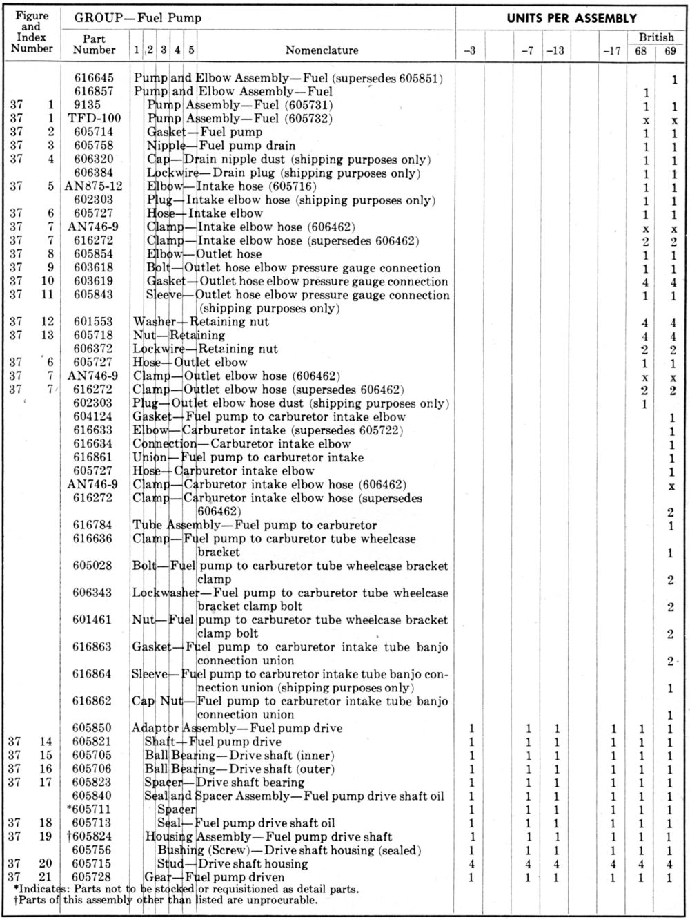
PM-102-A. Fuel Pump Drive. Ellor stated that the British fuel pump capacity was three times the need at sea level and adequate for operation at 20,000 ft, which provided for 2,280 lb at sea level and 760 lb at 20,000 ft. The proposed Air Corps pump substantially met these requirements. The British representatives raised a question about flexible connections and solid lines, inasmuch as they used flexible lines. Air Corps representatives stated that the flexible lines they had tested had not proven satisfactory and that they had to be procured for fixed lengths, which complicated the stocking problem. The parties finally agreed to use flexible connections AND solid lines on the first 12 engines for test purposes. The Air Corps representative stated that the ratio of 2,500 rpm to 3,000 rpm pump speeds would be the maximum allowable by the Air Corps. Ellor stated that the specified ratio of 0.74:1 was satisfactory. The drawing was approved by Aspelin and the British representatives.
PM-103-A. Hydraulic Pump Drive. Hulman considered this drive satisfactory for the first 12 engines, and explained to Vincent why the Air Corps required an adapter bushing and adapter flange.
PM-104-A. Gun Synchronizer. Armament Laboratory's Fischer and Vincent discussed various possible methods of force-feeding lubrication to the gun synchronizer impulse generator, along with a means for returning oil to the system. Fischer was tasked with forwarding to Packard a proposed impulse generator pad cover; Packard was to formulate a scheme for forced lubrication. The drawing was otherwise satisfactory. [26 Aug 1940 Memorandum Report EXP-M-57-503-201, Conference Relative to Specification, Drawings and Engineering Requirements for the Packard Merlin XX Engine. 158 - 162.]
22 Aug 1940. Vincent wrote Col Echols expounding on another specification iteration based on the 21 August Wright Field conference. The following specification items were affected:
| Paragraph | Subject |
|---|
| C-1 | Material |
| E-4 | Complete Engine Dry Weight |
| E-7 | Overall Dimensions |
| E-10 | Protective Treatments, Coatings and Paint Finishes |
| E-14 | Pistons |
| E-19 | Fuel Metering Systems |
| E-25a | Straight Screw Threads |
| E-25b | Tapered Pipe Threads |
| E-29 | Engine Data Plate |
| F-1a | Method of Sampling, Inspection and Tests |
| F-2b | Magnetic Inspection |
Packard found it necessary to make the E-17 Ignition System, E-17a Spark Plugs, E-17b Radio Shielded Ignition Assemblies, and E-17c Magnetos item specifications broad enough to cover ignition equipment approved by both the British Purchasing Commission and the U.S. Government, meaning these items had to be separately approved by each Government. Item E-22 Coolant Temperature was changed to include the coolant liquid type, a change suggested by Barrington, Ellor and Reid. E-26e Gun Synchronizing Impulse Generator was changed to make the language more definite.
Vincent also sent revised drawings for the following:
PM-100B. Approved Propeller Shaft, Propeller Governor and Vacuum Pump Installation. This layout had been approved subject to a final check by the Curtiss and Hamilton Standard engineering departments; Vincent was to follow up and secure their approval.
PM-101B. Approved Generator Mounting and Drive. The drawing had been alteed to show oil drain and shipping cover.
PM-102B. Approved Fuel Pump Installation. After Ellor had advised Vincent that the 0.74:1 drive ratio would give capacity slightly in excess of the R-R pump and ratio. He therefore approved the fuel pump installation subject to final check on the hand-built engines.
PM-103B. Approved Hydraulic Pump Drive. A shipping cover had been added to the drawing.
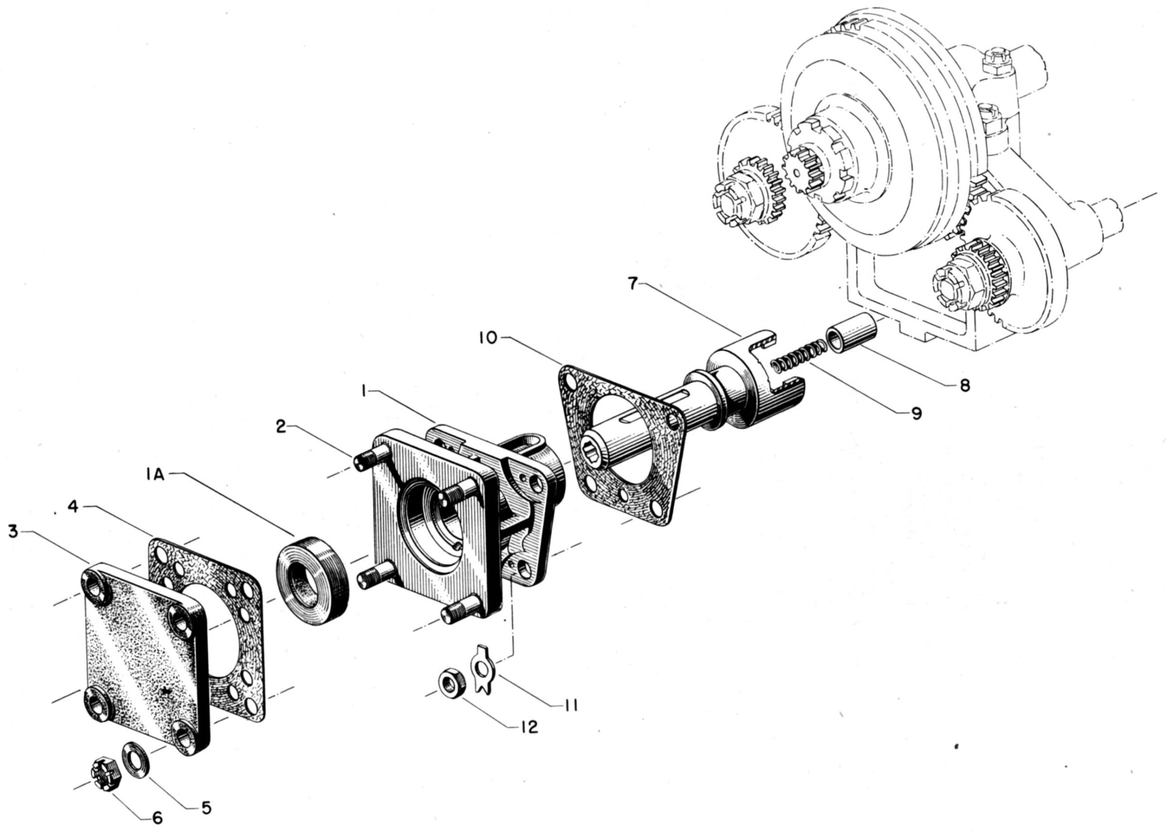
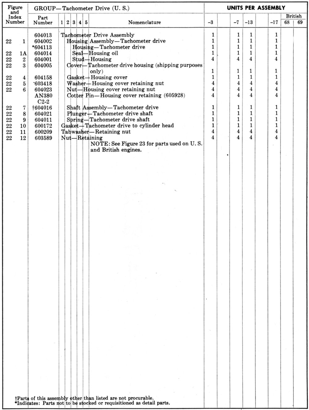
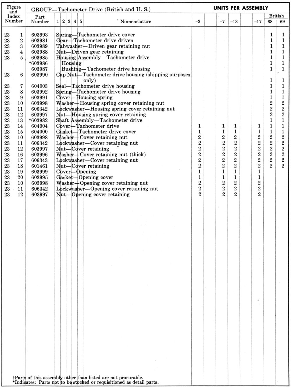
PM-104B. Approved Gun Shychronizer and Tachometer Installation. Packard had provided low-pressure lubrication for the gun synchronizer parts or for no oil, depending on the type of synchronizing mechanism installed.
All these revisions had been approved by Barrington, Ellor and Reid, who were to advise the British Purchasing Commission. [Letter, Vincent to Col Echols. 144 – 147.]
22 Aug 1940. Maj Carroll sent Vincent a copy of the NACA Technical Report No 218 Standard Atmosphere along with a B.G. Corporation drawing A-1115 showing a 14mm spark plug with external dimensions substantially the same as the KLG plug used in R-R engines. [Letter, Maj Carroll to Vincent. 138]
22 Aug 1940. George Mead wrote Brig Gen Brett, with a copy to Col Volandt, about the final allocation of Merlin engines. If the Merlin would reduce the number of Allison engines required, additional funds might be available that could be applied toward the Merlin purchase. At that time, funds were available for only about 2,000 Merlins, with an option for an additional 1,000. Packard had made good progress with its engineering and could start the patterns and dies immediately upon receipt of a letter from Gen Brett guaranteeing commitments for materials, etc. prior to the receipt of a contract. Mead thought it desirable to send Packard such a letter provided there were no doubts as to the contractual requirements. These engines were so badly needed that Mead was anxious to avoid any further delays if possible.
Packard had raised the question of R-R license agreements and Mead had suggested that Packard insert such wording as they deemed desirable to the effect that they would be relieved of an y responsibility to R-R insofar as fees or patent infringements were concerned. The actual license agreement was worked out by Treasury Secretary Morgenthau and he could explain the terms. Mead understood that the U.S. Government was free to use the R-R design without payment of any royalties. Irrespective of the agreement between the two Governments, R-R had furnished drawings, parts and the services of certain men. R-R should be reimbursed for such direct expenses chargeable to the Merlin development and production for the Air Corps' account. While in Detroit, R-R Representative Olley gave a statement of their expenses to date. Mead thought it in order for the Materiel Division Contract Section to reach an agreement with Olley and authorize Packard to reimburse R-R accordingly. [Letter, George Mead to Brig Gen Brett. 149 – 150.]
22 Aug 1940. Maj Carroll recommended that the Wright Field Propeller Laboratory Chief forward a copy of the 8 Aug 1940 Memorandum Report EXP-M-52-430-7, Propeller Requirements of P-38 and P-40 Airplanes Powered with Merlin XX Engines to Lockheed and Curtiss, requesting their comments on propeller selection. [Letter, Maj Carroll to Chief, Propeller Laboratory, Wright Field. 151.]
23 Aug 1940. Vincent reminded Col Echols of a discussion during his 21 August Wright Field conference where Ellor raised the question as to whether lubricating oil confirming to Specification AN-9532, dated 1 Mar 1939, Grade 1100, would be satisfactory for Merlin XX use. Ellor submitted for consideration a memorandum, Notes on Air Ministry General Specification for Lubricating Oils. Chenoweth had this memo copied and planned to check on just how the British specification differed from the AN specification. Vincent requested to be notified of the findings when they became available. [Letter, Vincent to Col Echols. 154.]
24 Aug 1940. American Bosch (hereinafter AB) Vice-President Foster N. Perry wrote Vincent following up on information provided by AB representatives Cherry and Wild on a 12-cylinder magneto for the Merlin XX. AB hoped that Packard would select an AB magneto based on designs developed to meet U.S. Army and Navy requirements rather than duplicating the English parts. The Merlin XX space limitations imposed a space handicap; the 12-cylinder mockup delivered that same week could not be suitably installed and driven on account of its 8-pole construction and basic 14-cyllinder frame. However, subsequent AB investigation had shown that a 12-cylinder version of the 9-cylinder, 4-pole AB magneto was practical. On the following Monday, Kiely and Tost planned a visit to Packard where they would deliver a 12-cylinder magneto mockup of the revised size and design, along with cost and availability data. Perry mentioned several factors that recommended the AB magneto:
(a) While having a flange and drive specific to the Merlin XX, the AB magneto was to be built to inch dimensions with standard U.S. threads, tapers, etc.
(b) A high parts percentage would be common to and interchangeable with those of other AB aviation magnetos and would meet Specification AN-9511.
(c) The electrical output was to be substantial, since AB planned to use its standard magnetic circuit, magnets and breakers. Any increase in electrical output potential over the BTH magneto should be credited to reserve safety; however, the energy delivered was only that necessary to break down the spark plug gap
(d) Mechanically, the AB magneto would have its usual advantages in stationary magnets, light-weight inductor rotor, exceptionally high-speed breaker mechanism (identical to 9-, 14- and 18-cylinder magnetos, cam operating at only half engine speed (which gave a certain latitude to engine designers), and automatic lubrication (no external magneto lubrication between engine overhauls).
(e) The AB magneto would be simplified by adherence to the standard American practice of using fixed spark timing on 9- and 14-cylinder engines. AB understood that the English magnetos had a variable spark timing range, but this should be unnecessary if controllable-pitch constant-speed propellers were used; AM thought variable spark timing unnecessarily complicated magneto design, impaired reliability, and resulted in cumbersome mechanical controls.
AB was hopeful that Packard would choose a magneto design based upon the fundamental features that had been developed to meet Specification AN-9511. [Letter, Foster N. Perry to Vincent. 165 – 166.]
26 Aug 1940. Vincent informed Col Echols that PPL ignition specialist T.T. Neill had spent a day conferring with Packard and AB magneto specialists Tost and Kiely discussing a proposal to develop an AB magneto for Merlin XX use; they reworked their 9-cylinder magneto into a form that would fit the Merlin XX. They mentioned that Air Corps was negotiating with AB and intended to place an order for a small number of hand-built magnetos. Neill made it clear that were such an order placed, it would be for experimental purposes only, with no obligation for a production follow-on order. Chenoweth had requested two Photostats of R-R Installation Drawing No. D-14005; Ellor went over these drawings with Neill and gave him material for several notes, copies of which Vincent requested. Vincent also provided Neill with photostats of the current British Thomas Houston (BTH) magneto outline and section drawings of the magneto currently installed on the British Merlin XX. [Letter, Vincent to Col Echols. 163 - 164.]
26 Aug 1940. A conference at Packard was attended by Ellor Reid and Olley of the British Purchasing Commission, Vincent and Griswold from Packard, and Neill from the Division; they discussed Merlin XX ignition equipment. Neill advised the several parties that regardless of what ignition equipment was selected as factory equipment on Merlin XX engines, the Division was going to secure experimental magnetos, shielding and spark plugs with a view to having such items available for replacements or as original equipment. Ellor stated that if the experimental magnetos gave improved performance the British as well as the Americans would be extremely interested. Vincent stated that plans were in progress to provide BTH magnetos from two sources by that the Division's experimental program appeared to be very reasonable. Neill expected the American designed and built Bosch magneto would be available in about three months and that samples would be tested by the Division and also supplied to Packard for their tests or submission to R-R if desired. He pointed out that British spark plugs for the Merlin XX cost about $5.00 each whereas the Division was confident that suitable American-designed substitutes could be procured for $1.00. This cost differential would amount to a very large figure and would even justify replacing the original British magneto if it was incapable of satisfactory performance with the American plugs and if the experimental American magneto proved satisfactory. BTH magnetos being procured for installation in the engines scheduled for delivery to England would include about 3,000 spares so that a sufficient quantity would be available for all 9,000 engines if desired. In any event, it was agreed that it would not be necessary for the Division to make a decision at that time. Neill volunteered to keep the interested parties informed of the experimental ignition equipment progress. After the conference the Bosch magneto mock-up was checked to determine its fit on the engine and to provide ample clearance at all points. [5 Sep 1940 Memorandum Report EXP-M-57-520-86. Conference with Representatives of British Purchasing Commission and Packard Motor Car Company on Ignition Equipment for the Rolls-Royce Merlin XX Engines. 181 – 182.]
27 Aug 1940. Maj Carroll wrote Vincent covering a revised PM-104 drawing that showed a suitable cover for the gun synchronizer impulse generator adapter drive. Maj Carroll promised a decision prior to engine production covering the gun synchronizer drive adapter and cover plates. [Letter, Maj Carroll to Vincent. 167.]
27 Aug 1940. Vincent conversed via telephone with Division's Chenoweth and J. Hulman regarding Merlin XX accessory drive drawings.
PM-104B. Gun Synchronizer Drive. This marked-up drawing showing proper outline and cover dimensions had been returned on 27 August.
PM-100B. Vacuum Pump and Propeller Governor Drive.
a. The propeller governor drive was satisfactory.
b. Vacuum Pump Drive
(1) The oil hole was not located exactly in accordance with specification dimensions and the oil hole size was not given.
(2) A plug should have been included in the shaft as per the applicable specification.
(3) The quill shaft should have been located so that it would not move forward.
(4) The 0.015" clearance between the quill shaft straight portion and the gear journal ID would permit excessive runout. Vincent agreed to reduce this clearance in order to maintain runout within the limits permitted by the applicable specification. Chenoweth cautioned Vincent that the design might still cause excessive pump and engine spline wear or excessive pump coupling wear. This matter would be settled during the type testing of the first 12 engines. Vincent said that, if necessary, changes would be made to provide a better-aligned shaft.
(5) No oil seal was provided. While this was acceptable for the first 12 engines, if oil leakage developed during type testing a seal would be required for the remaining engines.
[31 Aug 1940 Memorandum Report EXP-M-57-503-202. Telephone Conversation with Representative of Packard Motor Car Co. on Packard Merlin XX Engine. P121756.]
29 Aug 1940. Maj Carroll replied to Vincent's 10 Aug 1940 letter requesting comments on carburetor air temperature (CAT) control during Merlin XX production tests. The requirement for maintaining CAT was contained in Specification AN-9503a ¶ F-6f(4), which specified that the air temperature at the carburetor or air throttle entrance was to be maintained between 70°F and 90°F. This was intended to obtain CATs representing average in-service conditions. Excessive CAT was conducive to detonation, particularly at the takeoff power check required by ¶ F-5c(3). The 90°F top limit had accordingly been set as a reasonably safe operating temperature for this condition. If extremely low temperatures were permitted, the engine might pass an acceptance test, including the high-output checks, but when running at a minimum 70°F CAT, malfunction indication, such as poor distribution or spark timing, might not be apparent. If steam and water were available in sufficient quantities the equipment for cooling or heating the carburetor was not necessarily expensive. Maj Carroll promised to forward drawings of an intercooler that had been used extensively by the Division; these were sent on 7 Sep 1940.[186] [Letter, Maj Carroll to Vincent. 170.]
29 Aug 1940. Vincent called Chenoweth from New York City where he was working with the British Purchasing Commission on the Merlin XX engine contract. The Commission proposed to reduce the quantity of hand-built engines from 12 to 9 and Vincent wondered if this would affect the Air Corps. Vincent explained that if more than 9 engines were purchased they would have started delivering production engines and production engines could be used for experimentation if required. Vincent further stated this would not affect the 8 Air Corps engines but would reduce the engines available at Packard from 4 to 1. Chenoweth opined that Packard should have more than 1, but that 1 engine was acceptable from an engineering perspective. Chenoweth said that he would discuss the administrative and contractual effect with Division personnel later that day and notify him if there were objections.
Vincent said that the R-R engineers would very much like to change the Specification Air-1025-C ¶ B-1 requirement to, "This specification covers the requirements for Packard-Built Rolls-Royce Merlin Model XX Engine"; in addition they wanted to introduce into the heading "Rolls-Royce" ahead of the designation "Merlin XX." Chenoweth said that there was no Air Corps objection to either change.
Vincent stated that Packard had erroneously made the fuel pump drive ratio 0.71:1 instead of 0.74:1 and that the 0.71:1 ratio was considered too low; Ellor suggested the ratio be increased to 0.80:1. Chenoweth told Vincent this was satisfactory unless he was telephoned by someone from the Division later that day (no one telephoned). [3 Sep 1940 Memorandum Report EXP-M-57-503-205. Telephone Conversation with Colonel Vincent of Packard Motor Car Company relative to the Rolls-Royce Merlin XX Engine. P21741.]
3 Sep 1940. Vincent reminded Col Echols that on 22 August Vincent had enclosed Van Dykes and white prints of Specification No. Air-1025C, dated 20 Aug 1940, and that the specification had been brought up-to-date in light of decisions reached at the 21 Aug 1940 Wright Field conference. After checking with Chenoweth, who had no criticisms of the revised specifications, Vincent delivered a duplicate set to the British Purchasing Commission and discussed them with Alexander. Vincent then telephoned Chenoweth on 29 August and asked for permission to make the following minor changes:
• Specification page one changed the engine name from "Packard Merlin XX" to "Packard-Built Rolls-Royce Merlin XX". This was suggested by the British Purchasing Commission and recommended by the Packard attorney. Chenoweth concurred with this and agreed to inform Vincent if the Materiel Command legal department had any objections.
• Vincent asked for permission to change the fuel pump gear ratio from 074:1 to 0.80:1, a change recommended by Ellor.
Vincent did not want to change the specification number or date because these had been included in numerous places in the contract. Since the Division only had a one set of Van Dykes and one white print set, Vincent was sending new Van Dykes and white prints; he recommended destroying the old set the Division had on hand. Vincent delivered duplicates of these to the British purchasing commission on 30 August and also delivered a set to the Packard Legal Department for attachment to the contract. [Letter, Vincent to Col Echols. 175 – 176.]
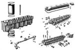 |
| Two-Piece Banks and Heads |
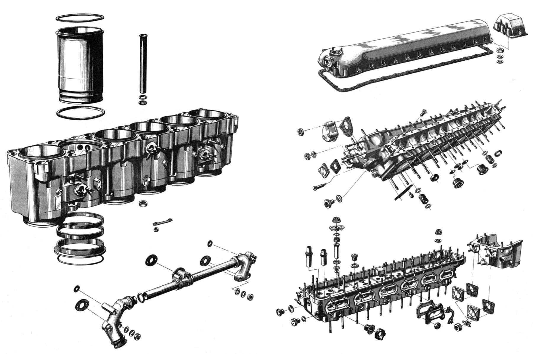
6 Sep 1940. In a letter to Col Echols, Vincent referred to an 8 August letter reporting a telephone conversation informing Col Page that Packard was considering tooling up for the two-piece Merlin XX cylinder block, which was recommended by Barrington, Ellor and Reid. Vincent was thoroughly sold on the two-piece construction. At Packard's request Barrington, Ellor and Reid had cabled R-R to obtain its approval of the two-piece construction. Vincent enclosed a cablegram photostat from then R-R General Works Manager Ernest Hives advising that the two-piece head was approved by the British Air Ministry Technical Department and R-R. Vincent felt sure the Division would also approve this construction and was proceeding with it. Vincent sent a copy of this letter to the British Purchasing Commission to also obtain its approval. [Letter, Vincent to Col Echols. 183.] Maj Carrol acknowledged receipt of relevant letters and raised no objection to this method of Merlin XX construction. [Letter, Maj Carroll to Vincent. 194.]
6 Sep 1940. Maj Carroll informed Vincent that the Division planned to purchase 11 hand-built experimental Merlin XX magnetos from AB; 6 would be right-hand rotating and 5 left-hand rotating since the magnetos on either side of the Merlin were note interchangeable. A final mock-up of this equipment was to be obtained in the near future and sent to Packard for inspection. When some of the magnetos were delivered to the Division, samples were to be sent to Packard for any use it might make of them, including possible submission to R-R. The AB magnetos were to be equipped with spark control, which could be directly connected to the R-R boost regulator by the same linkage now used. The Division did not concur with some points raised in the AB letter. [Letter, Maj Carroll to Vincent. 184]
9 Sep 1940. Vincent had written the Curtiss Propeller Division of the Curtiss-Wright Corporation and Hamilton Standard Propellers covering a marked print that he hoped would facilitate a final decision regarding propeller governor mounting. He sent copies of the print and correspondence to Col Echols. [Letter, Vincent to Col Echols. 187.]
9 Sep 1940. Vincent acknowledged the Division's 6 September letter regarding generator and starter arrangements on R-R engines. Vincent observed that he had clearly understood the objections raised against the first generator design and had revised it to comply with the Division engineers' recommendations. He had been told that the revised design had been approved.
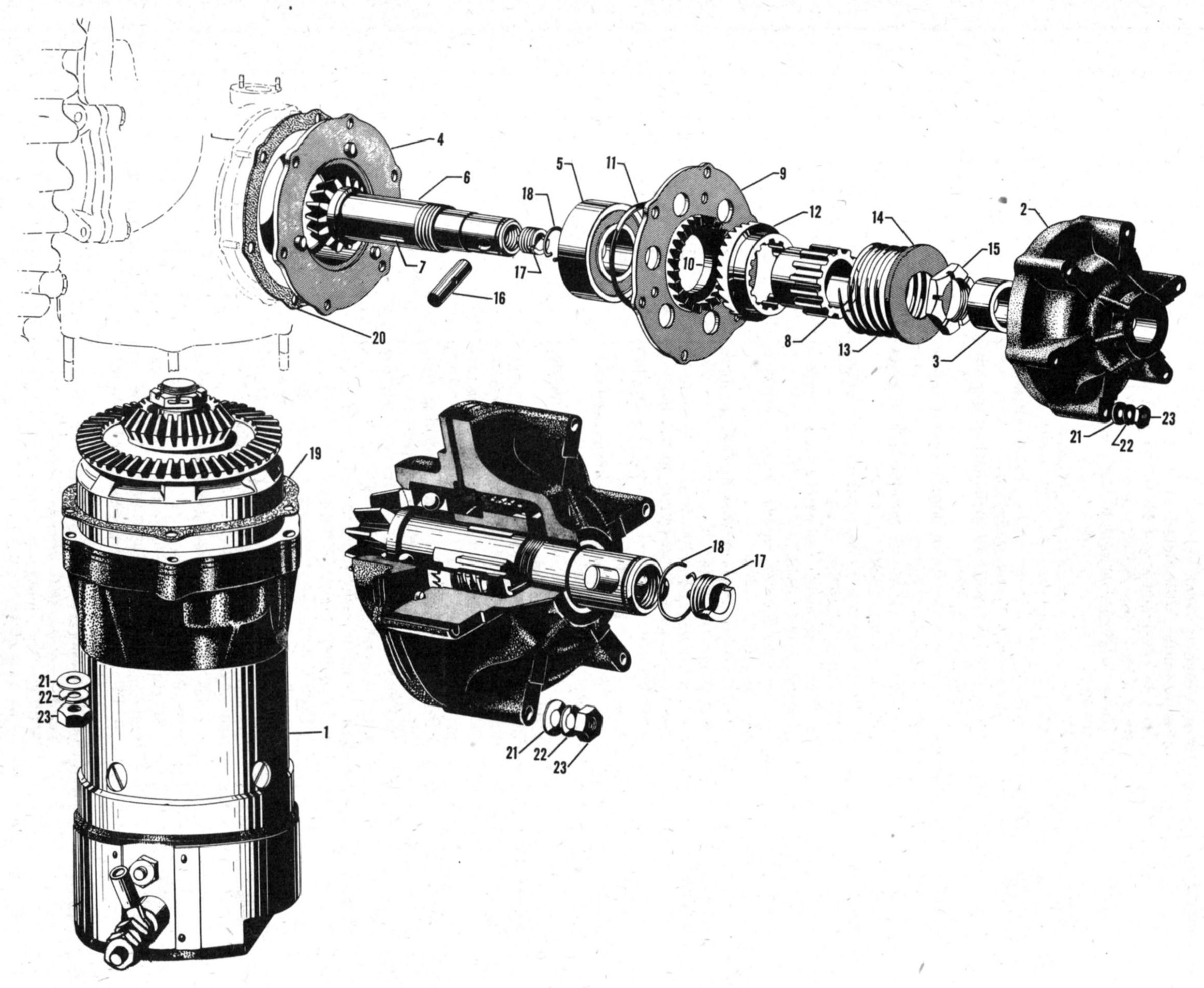
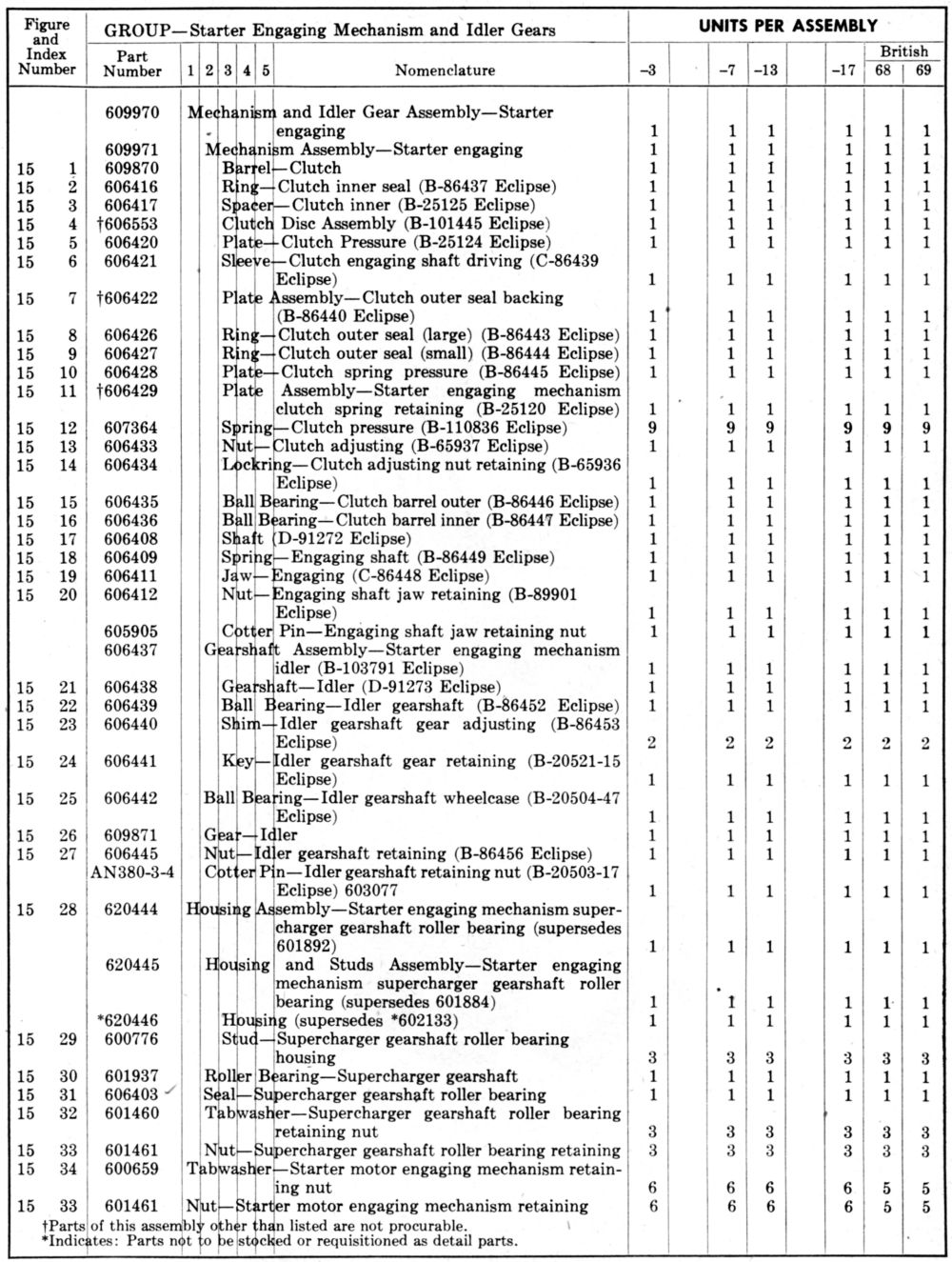
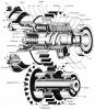
The Packard starter arrangement was based on a layout made by the Eclipse Aviation Company and the design was approved except for the starter cable connectors. This design had been rechecked and Vincent was enclosing two revised layouts:
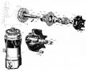
PM-105X. Approved Starter Motor and Reduction Gear Assembly for the Packard-Built Rolls-Royce Merlin XX Engine.
PM-106X. Approved Starter Clutch and Gear Drive Assembly for Packard-Built Rolls-Royce Merlin XX Engine.
After the Division approved the layouts, Packard proposed to remove the "X" from the number and furnish Van Dykes to the Division. [Letter, Vincent to Col Echols. 188.] These layouts were both approved by the Division and Maj Carroll so informed Vincent in an 11 September letter. [190.]
 |
 |
 |
 |
 |
 |
| Starter Motor and Reduction Gear Assembly |
Starter Clutch and Gear Drive |
10 Sep 1940. Maj Carroll informed Vincent that the accessory drawings Packard had submitted by letter on 3 September were satisfactory except for an error on PM-102B; the change block correctly reflected the speed ratio change from 0.74:1 to 0:80:1, the middle view retains the 0.74:1 legend on the mounting flange; Maj Carroll recommended a correction. [Letter, Maj Carroll to Vincent. 189.
12 Sep 1940. Maj J.A. Madakasz, Central District Accountability Officer, sent Vincent a shipping ticket CD31-3492, covering the R-R Merlin flight tool kit and log book that had been transferred to Packard from Ford. Maj Madakasz requested that if such material had been received, the attached shipping ticket be signed in duplicate and returned to his office. [Letter, Maj Madakasz to Vincent. 192.]
19 Sep 1940. Maj Carroll informed Packard that its 6 Sep 1940 letter had been received and that the Division had no objection to the proposed two-piece Packard-Merlin XX cylinder construction. [Letter, Maj Carroll to Vincent. 194.]
21 Sep 1940. Curtiss Aeroplane Division Chief Engineer Don Berlin wrote Col Echols regarding R-R Merlin XX installation in P-40D Airplanes. After examining the 17 Aug 1940 letter comments and enclosures, Curtiss Aeroplane Division concurred with the Division's comments on coolant, oil and fuel systems. However they suggested that in place of making two experimental installations, one according to British practice and one according to Air Corps practice, that Curtiss furnish installation drawings of the coolant, oil and fuel systems in accordance with Air Corps practice and submit these installation so R-R for approval. To date, Curtiss Aeroplane Division had a patched small photostat of the Merlin X engine, No. D-9022, lacking basic information necessary to complete a study of this engine installation in the Curtiss P-40D airplane. Complete information should be furnished, relative to the engine mounting lugs, location of all accessories and dimensions of mounting flanges and drive shafts. Coolant, oil and fuel connections should be located and sizes given. Carburetor details should be furnished, with strainer and control locations and flange dimensions for mounting carburetor air intake ducts. A detailed engine specification was to be made available to Curtiss Aeroplane for information concerning power, heat rejection , accessories, oil and fuel pressures and consumptions, oil and coolant flows, etc.
The engine controls illustrated on R-R Drawing No. D-9022 would not be suitable. Definite detailed information concerning separate throttle, mixture supercharger and propeller control is essential. It is noted that the British propeller shafts are different from those built in the U.S. Curtiss Aeroplane desires information as to the propeller shaft type that will be built in the U.S. As outlined above, there is not sufficient information to complete a comprehensive study of the R-R Merlin XX installation and Curtiss Aeroplane requested that information be supplied as to when Packard will have complete installation drawings. A mock-up or actual engine should be made available as soon as possible. [Don R. Berlin, Curtiss Aeroplane Division Chief Engineer, to Col Echols. 195 – 196.]
23 Sep 1940. During a Wright Field conference with Ellor representing the British Purchasing Commission, and Capt G.F. Smith, Dunham, Reichert, and Weldon Worth representing the Division, it became evident that, in summary, the Merlin XX would not function properly with the glycol system used on Air Corps engines and the installation of a 70% water and 30% glycol system operating under pressure would be necessary. The Division had no experience with such an installation and since it imposed new limitations on the radiator and cooling system, it was desirable to follow British practice completely if such details were available; this should produce an optimal installation in minimum time. If the Air Corps was to adopt an entirely new system and accessories with which there was no previous experience, it was very important to have available details that would permit production and procurement, along with engineering information, design and performance criteria, and specifications for the various system elements. The Division anticipated difficulty that would require modification to the coolant flow, horsepower, radiator types, etc., all of which would be facilitated if engineering data and previous experience were on hand. The situation was explained to Ellor, who said most such information was not immediately available; the Division agreed to write Ellor outlining the specific information needed and he would attempt to furnish it. The interesting engineering details that emerged during the meeting are applicable to liquid-cooled engine installation even today and are summarized below.
Because the 70/30 water/glycol mix has a higher coefficient of heat transfer, R-R engines had more satisfactory service experience with this mixture. A pressurized cooling system was necessary to avoid coolant boiling when operating at temperatures of 120°C at altitude. Ellor stated that normal R-R installations addressed English summer conditions with 23°C ground temperatures using 14 – 16 psig pressure. When operating the same aircraft under tropical conditions with ground temperatures of 41°C, a 30 psig header pressure was required. This was the pressure at which the expansion tank relief valve would operate. With such a system the radiator, tanks and plumbing test pressures was 50 psig. During fabrication, the radiator was subjected to 30 psig and immersed in cold water and then hot water or steam for six cycles; the Division had no such comparable test. With pressure systems, some part is always at the boiling point and in order to maintain proper flow it was necessary that this boiling point be in the expansion tank and not the pump inlet. Air Corps systems could be operated with any reasonable pressure drop through the radiator, the P-40 having about 8.5 psig pressure drop at maximum coolant flow when the coolant was 100% ethylene glycol. However, with the pressure system the radiator pressure and temperature drops must be so related that the liquid has a tendency to boil at the radiator inlet than the outlet. It was therefore necessary to provide a radiator pressure drop not exceeding 2.5 psig. British installations normally obtained this with a 90 gpm flow at 120°C; the same system at 60°C had a 140 gpm flow. Oil coolers were tested at 100 psig. Ellor stated that the Supermarine Spitfire radiator contributed 5% to the total drag. They had not considered using any oil coolers except the core tube type similar to those used in the U.S., except that they were frequently made in rectangular or elliptical shapes. They used only soft solder in radiator assembly and had previously used core tube radiators, but had recently concluded that fin and tube radiators were more desirable. They considered the Morris fin and tube radiator to be the best after the following comparison between the Morris radiator and one made from 5 x 300 mm core tubes:
| | Core Tube
5 x 30 mm | Morris
Fin and Tube |
|---|
| bhp/100°C/ft² Frontal Area | 264 | 266 |
| Static Drop at 100 fps Velocity (inH20) | 13.5 | 11.5 |
| Core Block Weight with Water per ft² Frontal Area (lb) | 55 | 40 |
| Depth (in) | 12 | 9.25 |
From another Table:
bhp/100°C/ft² Frontal Area
| IAS | bhp |
|---|
| at 200 mph | 290 |
| at 100 mph | 184 |
The Morris fin and tube radiator used a liquid tube 2.0" wide, 0.086" across, with a 0.006" wall thickness. These tubes were spaced laterally 0.5" apart and at 4.5" center line distance of 0.2328"; the fins were 0.004" thick and 9.2" deep, but the fin spacing used was not available. The fins were waved in the fore and aft direction to improve the heat rejection and the edges were foledd back on the fin to increase the core face strength.
Ellor stated that R-R engines typically dissipated heat equal to about 47% of the bhp to the engine cooler. This was substantially higher than U.S. engine heat rejection, but at the time the heat rejection to the oil in most Air Corps engines was substantially higher than the British engines. Ellor gave the following information in three British aircraft:
(1) Spitfire No. 1 at 367 mph speed, 1,030 bhp, at 18,000 ft and a climbing speed of 170 mph used a 7 x 320 mm core tube radiator with 1.85 ft² frontal area and two 6" oil coolers in series fabricated from 7 mm x 9" core tubes.
(2) Spitfire No. 3 used a Cerk 5 x 300 mm core tube radiator with a 1.95 ft² frontal area.
(3) The Bull Fighter, with a 360 mph top speed at 23,500 ft, used a Morris fin and tube radiator with a 2.05 ft² frontal area and had a suigability of 1.1. The core tube oil cooler in this installation was made from 5 x 300 mm core tubes with a 0.46 ft² frontal area. This used a pressure cooling system.
Ellor recommended using fin and tube radiators similar to the Bull Fighter's, and could obtain a sample for examination and testing if it were covered by an Air Corps purchase order. Division personnel pointed out the slow procurement process, and a letter to Ellor was drafted stating that during the 23 Sep 1940 Wright Field conference it was pointed out that if the Air Corps was to follow British R-R engine installation practices, it would need complete construction details, engineering processes, design criteria, performance characteristics and other pertinent engineering information. Specifically:
a. Radiator
(1) Name and description of the recommended core type with detail drawings of all physical dimensions such as tube size and spacing, fin size and spacing, total direct surface, indirect surface, etc.
(2) Performance characteristics for the recommended core throughout the airflow range showing heat rejection at varying airflows, varying 30% glycol liquid flow, and pressure drop for both the air and liquid.
(3) Header tank construction details, such as complete detail drawings of a radiator then giving satisfactory service that was most like the recommended radiator.
(4) Recommended details for the radiator to be used in a P-40 installation, including frontal area, header dimensions, core width and depth, and the maximum allowable pressure drop across the radiator under operating flow conditions.
b. Oil Cooler
(1) Complete recommended oil cooler detail drawings including core details.
(2) Performance characteristics, including heat rejection at varying oil and air flows, the oil pressure drop through the cooling passages and through the bypass connection under given conditions, and any available data on the effectiveness of the warm-up jacket and the oil cooler ruggedness under pressure cycling.
c. Oil Cooler and Radiator Mounts. Detail drawings of a recommended mount and any related data or requirements such as the required flexibility or natural frequency, etc.
d. Radiator and Oil Cooler Inlets. Shape, area and inlet location detail drawings of a similar installation.
e. Radiator and Oil Cooler Ducts. Detail drawings of a recommended installation with particular reference to attaching methods and duct sealing to the radiator and oil cooler or at points where flexibility could be incorporated.
f. Shutter Details. Recommended shutter detail drawings.
g. Shutter Controls. Detail drawings of recommended shutter controls including engineering specifications and design data giving the required operating pressures and recommended shutter operating loads at various positions and airspeeds.
h. Radiator Thermostatic Bypass Valve. Detail drawings and manufacturing processes including all material specification and component parts, bellows performance specifications and test requirements, filling unit vapor pressure, the pressures and temperatures defining each end of the operating range, maximum back pressure, pressure drop through each normal passage, etc.
i. Expansion Tank Valve. Detail drawings and manufacturing processes including all material specifications and component parts, performance specification and test requirements for the bellows, the filling unit vapor pressure, the pressures and temperatures defining each end of the operating range, maximum back pressure, pressure drop, etc.
j. Viscosity Valve. Detail drawings and manufacturing processes including all material specifications and component parts, performance specification and test requirements for the bellows, bellows pressure throughout the operating range, the pressures and temperatures defining each end of the operating range, maximum back pressure, pressure drop, etc.
k. Expansion Tank. Detail drawings and engineering data or performance characteristics, coolant flow range for which it was suitable, inlet and outlet static pressures through the normal flow range, and operating limits.
l. Connections. Detail drawings and specifications for the recommended lines and connections, together with engineering data on the burst and blow-off pressures, and any other available performance data.
m. Coolant. Engineering specifications including the recommended corrosion inhibitor.
n. Engine Date, if Available.
(1) Coolant flow with 30% glycol at varying temperatures and independently varying inlet and outlet pressures.
(2) Heat rejection to the coolant for normal operating conditions including 60% rpm for ground cooling.
(3) Oil flow and heat rejection to the oil for all engine operating conditions.
(AUTHOR'S OBSERVATION: One wonders if the foregoing was a joke. JEEZ, why not just have the Brits design the whole damned airplane? No, wait, isn't that what happened when the Brits approached North American Aviation about building the Curtiss P-40 under license and North American thought it could build a better airplane faster by starting from scratch. And then when the first Allison-powered P-51s delivered lackluster altitude performance, the Brits installed a Merlin at Hucknall and reworked the cooling system to produce the airplane performance for which the P-51 became famous. [see Birch, David Rolls-Royce and the Mustang. Rolls-Royce Heritage Trust Historical Series No. 9, 1987]) [1 Oct 1940 Memorandum Report EXP-M-57-503-227. Cooling System Installation of the Rolls-Royce Engine, Packard-Merlin XX. 203 - 209]
27 Sep 1940. Maj Carroll wired Vincent with news that Don Berlin, Curtiss-Wright Chief Engineer was anxious to visit Packard and discuss Merlin XX installation in P-40 airplanes. The Materiel Division had no objection to discussing installation problems. [Telegram, Maj Carroll to Vincent. 200.]
30 Sep 1940. Vincent wrote Col Echols explaining Packard's geometric dimensioning and tolerancing convention for a drawing PM-100B dimension. The Division had suggested specifying the dimension as 17/64" or 0.265" with a tolerance limit of +0.020" and -0.000", which meant the dimension could be anywhere between 0.265" and 0.285". Packard's standardized detail drawings called for a ±0.010" dimension limit unless otherwise specified. [Letter, Vincent to Col Echols. 202.]
1 Oct 1940. Vincent wrote Col Echols relating a 1 October telephone conversation with Power Plant Laboratory Chief Col Edwin R. Page during which Merlin XX production test equipment was discussed. Packard had thoroughly studied the equipment used by Allison, Pratt & Whitney and Wright in an effort to reduce noise levels that would allow test buildings a convenient location from the Detroit assembly department. Modern induction dynamometers in sound-insulated test cells in conjunction with water-cooled exhaust mufflers would be needed to secure satisfactory noise levels. Packard recommended installing 37 such test cells for production acceptance. An additional 3 fixed test cells would be needed for type tests and other miscellaneous tests where a propeller would be used. Col Page advised that the proposed test equipment would be entirely satisfactory to the Air Corps; Packard was to begin construction immediately. [Letter, Vincent to Col Echols. 210.]
1 Oct 1940. Air-Maze Corporation representatives Glanzer and Lutz met with Capt D.J. Keirn regarding Merlin XX backfire screens. They exhibited samples of Air-Maze screens that were cheaper and lighter than the equivalent R-R part. Keirn informed them that no specification changes were to be made except those necessary to adapt Air Corps accessories. [11 Oct 1940 Memorandum Report EXP-M-57-525-12. Conference on Backfire Screens for Packard Rolls-Royce Engines. 212.]
24 Oct 1940. McDonnell Aircraft Corporation Vice President for Engineering Ivan H. Driggs wrote the Materiel Division Chief Experimental Engineer requesting Merlin engine power curves with the various degrees of supercharging proposed. [Letter, Driggs to Materiel Division. 213.] on 6 Nov 1940, Maj Carroll replied to Driggs' request enclosing photostatic copies of available Merlin XX power curves; these did not include maximum continuous power as such curves would not be available until after type testing had been accomplished. [Letter, Maj Carroll to Driggs. 216.] On 18 Nov 1940, Driggs wired Wright Field inquiring whether the Merlin XX was to be built with a low-altitude blower for application with turbosupercharger. [219.] On 19 Nov 1940, Lt Col Carroll wired Driggs saying that the Merlin XX with a turbosupercharger was not contemplated.[220.]
23 Oct 1940. The Koppers Company, a propeller manufacturer, requested drawings showing the SE No. 50 propeller shaft. The Wright Field Production Engineering Section replied that such drawings were part of AN Specification AN-9506, which had a restricted classification. Production Engineering enclosed an agreement for Koppers to sign and provided AN-9506 upon receipt of the signed agreement. [Cross Reference 400.11 – Spec K. 215.]
30 Oct 1940. Capt C.S. Irvine reported on a conference at Packard attended by J.G. Vincent, Chief Engineer; R.E. Brown, Aircraft Production Chief; G.H. Brodie, Business Manager; and R.N Dubois, Test Supervisor; all of the Packard Motor Car Company. Also in attendance representing the British Purchasing Commission were John Reid, Production Supervisor; and James Ellor, in charge of development. Irvine recommended that a serious effort be made to obtain an American spark plug for the R-R engine inn view of the high cost and non-interchangeability of the British Plug. He further recommended development and test of a 14mm ceramic plug and opined that the new B.G. spark plug design utilizing platinum electrodes and gap clearances of 0.005" be investigated as possible solutions. [Cross Reference 333.1. 214.]
16 Nov 1940. During his 14 Nov 1940 visit to the Materiel Division, Vincent announced that Dr. Lassels planned to visit the Materiel Division during the coming week to discuss with Materials Laboratory personnel material for the Merlin XX. Vincent had brought a copy of Packard Specification No. PM-754, dated 5 Nov 1940, covering the aluminum alloy proposed for the sand casting of highly stressed parts. Vincent stated that there had been considerable argument concerning this specification and that is was being forwarded to the Materials Laboratory for its study prior to the Lassels visit. [IOM, Col Page to Chief, Materials Laboratory. 218.]
23 Nov 1940. Lt Col Carroll sent DuBois the exhaust system and dynamometer coupling drawings for R-R Merlin X engines that he had requested. He also sent drawings for a dynamometer coupling usable on the Merlin XX. [Letter, Lt Col Carroll to DuBois. 221 – 222.]
29 Nov 1940. Lt Col Carroll wrote Packard requesting copies of the pressure coolant system it had designed for the Merlin XX test stands; the Division would be needing similar stands in about one month. [Letter, Lt Col Carroll to Packard. 223.] On 3 Dec 1940, Packard sent its own drawing No. M.W.-38, Coolant System Diagram for Proposed Production Dynamometer Stands, along with R-R Glycol Filter for Engine Cooling photostats. [Letter, DuBois to the Division. 226.]
3 Dec 1940. McDonnell Aircraft's Driggs wrote the Wright Field Chief Experimental Engineer inquiring whether the Merlin XX could be installed in a pusher configuration. [Letter, Driggs to Wright Field. 227] Lt Col Carroll replied on 13 Dec 1940 stating that the Merlin XX was not equipped for pusher installations and that no such feature was contemplated. [Letter, Lt Col Carroll to Driggs. 228.]
16 Dec 1940. Packard Chief Metallurgist W.H. Graves sent a copy of Air Ministry Specification T.T.D. 44C covering lubricating oil specified for use on the control mechanism for the R-R engine. This control mechanism was a small gear box with small plain bearings and small rolle bearings that operated the throttle, magnetos and boost control. Graves thought it would be unnecessary to use a special lubricant and wondered if the Air Corps had some standard lubricating oil of similar characteristics and could suggest a specification number. [Letter, Graves to Johnson. 229.] Lt Col Carroll replied on 23 Dec 1940, enclosing a copy of Air Corps Specification 2-27D. He noted that the two specifications were in close agreement except for the inclusion of stearic acid (a mild extreme-pressure compound) in the British specification. The Division agreed that a special lubricant would not be necessary and recommended Air Corps Specification 2-27 oil. Actual service tests would be required to determine which oil would provide longer equipment service life. [Letter, Lt Col Carroll to Grant. 230.]