Packard Builds the Rolls-Royce Merlin
Part 1: 1937 – 16 August 1940. Specification and Drawing Negotiations
Compiled by Kimble D. McCutcheon
Published 21 Jun 2026

Packard V-1650-3 (NARA) |
Much has been published about the Packard Motor Car Company's heroic efforts to mass-produce the Rolls-Royce Merlin in the United States using American mass-production practices. Packard undertook numerous formidable challenges and produced an engine equal to, if not better than, the original Rolls-Royce design. This article aims to address Packard's role in unprecedented detail — not only the technical aspects of drawing conversions and faster manufacture, but also the negotiation of specifications simultaneously acceptable to Packard, the U.S. Army Air Corps, and the British Purchasing Commission.
Unless otherwise noted, this article is based on U.S. National Archives Record Group 342, RD2441, R-R Merlin (Packard Built), 1939-42. Page numbers pertain to these records after they were chronologically organized; there is no logical order to the NARA documents. |
 |
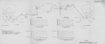
| PM01 Fig. 1. Merlin versus Allison Output |
2 Jul 1937. Wright Field (hereinafter WF) Power Plant Laboratory Civilian Engineer Opie Chenoweth published a report comparing the Allison V-1710 to the Rolls-Royce (hereinafter R-R) Merlin (no specific models were specified); the Allison had just been the world's first engine to pass a type test with a takeoff rating of over 1,000 hp, and R-R Merlin altitude performance data had just become available. The V-1710 achieved its altitude performance with the addition of an exhaust-driven turbosupercharger. PM01 Figure 1 curve E shows the maximum Merlin output while curve G shows the V-1710 normal output when fitted with a turbosupercharger. The 1,000-hp V-1710 takeoff rating was expected to increase to 1,150 hp in later engines by overspeeding from 2,600 rpm to 2,950 rpm. Curve F shows the normal V-1710 takeoff power reduction with altitude without turbosupercharging; curve H shows the 5-min takeoff rating, allowing curves E and H to compare Merlin and V-1710 on equal footing.
Chenoweth concluded that the V-1710 was superior to the Merlin in the two areas labeled A and inferior in the two areas labeled B. However, based on the 1,150 hp rating, area C values could be used for 5 minutes as shown by area D to obtain power outputs at all altitudes that were 35 hp to 150 hp greater than the Merlin. The Merlin takeoff rating was only 900 hp, giving the unturbosupercharged V-1710 a 250 hp takeoff power advantage and the turbosupercharged V-1710 a 385 hp advantage for 5 minutes. Merlin and V-1710 frontal areas were 5.85 ft² and 5.91 ft², displacements were 1,645 in³and 1,710 in³, and dry weights were 1,385 lb and 1,300 lb (1,525 lb with turbosupercharger). [2 Jul 1937 Memorandum Report E 57-1643-1, Comparison of R-R "Merlin" and Allison V-1710 Engines. US NARA RG342 P063015.]
Author's Observation: The foregoing is an example of the magical thinking that lured the U.S. Army Air Corps (USAAC) into building the single-stage V-1710 and depend on turbosupercharging for altitude performance. In the real world, turbochargers were voluminous, expensive, heavy and depended on several critical metals that became scarce in wartime. As a result, the Lockheed P-38 and Republic P-47 were the only production USAAC fighters with turbosuperchargers. Other aircraft using the V-1710 were inadequate at altitude. It was indeed fortuitous for the U.S. that Packard produced the Merlin under license.
3 Apr 1940. Chenoweth proposed the following procedures for testing the two Merlins that had been procured for experimental investigation:
Engine No. 1
a. Dismantle the engine completely for minute examination and invite representatives from the aircraft engine industry, Navy Bureau of Aeronautics (BuAer) Engine Design Section, Civil Aviation Authority, National Advisory Committee for Aeronautics and Bureau of Standards to the WF Power Plant Laboratory (PPL) to attend.
Engine No. 2
a. Install on the altitude test stand and conduct the 25-hr altitude test required by the standard Army-Navy 150-hr type test.
b. Perform calibration run including supercharger efficiency.
c. Tear the engine down for inspection and replace any necessary parts.
d. Complete the 150-hr test on the torque stand in accordance with the procedures defined by Request for Data R-40-A, Engines, Aircraft, 1,800 – 2,400 hp.
e. Tear the engine down completely for inspection and, dependent upon results, decide whether the industry should be invited for a second inspection.
This scheme allowed studies of the two engines to proceed concurrently and produce performance data for the industry shortly after its representatives had inspection Engine No. 1. The standard 150-hr type test obtained both performance and durability data.[3 Apr 1940 Memorandum Report EXP-M-57-503-116, Test Program for R-R Merlin Engines. US NARA RG342 P121255.]
18 Apr 1940.Office, Chief of the Air Corps (OCAC, i.e., Gen George H. Brett) Technical Executive (TE) Maj A.K. Lyon reported that Group Captain Pirie, British Attaché for Air, had loaned sketches, data, Merlin engine installation drawings and a propeller hub drawing so that preparations could begin for a Merlin engine test rig. The engines were being shipped on 18 or 19 April and were expected to be in the U.S. about 30 May.[IOM, Maj Lyon to TE, WF. 5.]
2 May 1940. The OCAC TE reported that two Merlin X engines were due to arrive in New York about 5 May. Maurice Osborne, a R-R representative then in Canada, was available to visit WF and assist with testing these engines. A Spitfire airplane was to be ready for flight test, probably at Trenton, about 70 mi east of Toronto on Lake Ontario, about 10 May.[Telegram E-441, OCAC TE to WF TE.]
Monday, 20 May 1940. Chrysler Corporation’s Kaufman Thuma (K.T.) Keller visited Treasury Secretary Henry Morgenthau, Jr. in Washington, DC at Mortgenthau’s request. Mortgenthau was marshalling the captains of industry with hopes of redirecting American industrial capacity toward building materiel needed for the upcoming war. Morgenthau and Keller discussed the possibility of Chrysler building Allison, Continental and R-R engines. [23 May 1940 Letter to Treasury Secretary Henry Morgenthau, Jr. from Chrysler president K. T. Keller. RG18E290B8081.] The OCAC advised WF via teletype E-634 on 21 May 1940 that Chrysler representatives would arrive at WF the next day to discuss Continental and view R-R engines. Two R-R Merlins were arriving express from New York via Columbus on train No. 31 at 0729 on 21 May 1940. OCAC instructed WF to uncrate the engines and disassemble one to the extent practicable so that Chrysler could examine it. OCAC requested that Maj Edwin R. Page, Opie Chenowith and Ford L. Prescott be available for discussions and to furnish a report to Gen Brett no later than Thursday night (23 May 1940). OCAC directed Col Kenney to give the project his personal attention and to see that these plans were carried out.[Cross Reference to Materiel Division from Office, Chief of the Air Corps (OCAC). RD3023B2790.]
After Chrysler personnel examined the Merlin engine, Keller wrote Morgenthau stating that, although Chrysler was new to the field of aircraft engines and aircraft engine production, and would require extensive reorganization of facilities and personnel, it did possess unique facilities for engineering research along with background and experience with production problems. Chrysler's study of the Merlin had convinced it that would be more expeditious to design a new engine than to produce the Merlin.[23 May 1940 Letter to Morgenthau from Keller. RG18E290B808.]
Morgenthau responded: “Since you make it clear that you are no longer interested in ‘the R-R job’, which I have discussed only with you, I want you to know that I intend to explore the possibilities with other manufacturers. Your letter makes plain that you will entertain no objection to this course.” Morgenthau left the door open for Chrysler to mass-produce the Continental engine.[27 May 1940 Letter to Keller from Morgenthau. RG18E290B808.]
Author's Note: This was the beginning of the Chrysler XI-2220 and the beginning of the U.S. Government's attempt to license-build the R-R Merlin.
20 May 1940. Capt George E. Price flew a Supermarine Spitfire that had been brought from Canada and submitted a report of his observations. [20 May 1940 Memorandum Report PHQ-M-19-1092-A. Pilot's Observations on Supermarine Spitfire Powered with Merlin Mk III. F020966.]
14 Jun 1940. G.H. Brodie, Packard Motor Car Company (hereinafter Packard) Engineering Division Business Manager, wrote WF with thanks for the May 17 letter with reference to accessory drive locations and types pertinent to Merlin installation.[Letter, Brodie to Col Echols. 8.]
15 Jun 1940. Maj Lyons telegraphed Col Echols on behalf of Gen Brett with information meant to govern the manufacture of Merlin XX engines under license.
1. The Anglo-French Purchasing Board, Air Corps and BuAer were to meet at WF and draft a tentative specification covering detailed test accessory requirements essential to Merlin installation in Army and Navy aircraft.
2. Capt Snodgrass, OCAC, was bound for WF to draft a tentative contract in collaboration with Anglo-French Purchasing Board and Aeronautical Section of the Advisory Commission to the Council of National Defense representatives.
3. The contract was to consider the Army requirement for the Merlin XX as a substitute for the Allison V-1710 engine in 373 twin-engine pursuit aircraft (Lockheed P-38) and 885 single-engine pursuit aircraft (Bell P-39) scheduled for procurement on the 3,000 airplane program approved in Second Supplementary Estimates, Fiscal Year 1941.
4. Contract preparation was to consider the decision to expedite American R-R Griffon production as a substitute for the Continental 1,500 hp engine.[Telegram C-391, Gen Brett to Col Echols. 9 – 10.]
Col Echols responded with confusion over the idea that the newly-built Merlins were to be used in the 3,000-plane program when WF had been unable to get any detailed installation drawings and make changes to existing aircraft. It would take months to engineer the substitutions. Further, the Merlin had not yet been qualified as a service type; much testing remained. Materiel Command (hereinafter MatCmd) planned for all 3,000 aircraft would be delivered before the end of 1942. It made more sense to proceed with Merlin development and manufacture so that it could be used in aircraft subsequent to the 3,000-plane program. According to information obtained by Maj Carroll, only one Merlin XX had flown and Col Echols thought it a major gamble to install Merllin XXs in large quantities immediately. Col Echols wanted to know when the PPL would be authorized to begin testing the Merlin X then on hand.[Telegram DHQ-T-797, Col Echols to Gen Brett. 11 - 14.]
19 Jun 1940. Maj Lyon informed Col Echols that Dr. George J. Mead, Chief, Aeronautical Section, The Advisory Commission to the Council of Nation Defense, suggested Col Echols call Mr. AM Wibed, Ford Motor Car Company Purchasing Agent, and arrange for Ford to take delivery on the disassembled Merlin at WF; Col Echols was authorized to release it on a memo receipt. It was satisfactory to have Capt Snodgrass go to WF on 19 Jun, confer with Shaw on 20 Jun, proceed to Dearborn, Michigan and confer with Ford attorneys as to general legal contract provisions on 21 Jun. Mead was very anxious for a plan of action on this matter. Maj Lyon was issuing orders covering these visits.[Telegram E-904, Maj Lyon to Col Echols. 17.]
22 Jun 1940. Gen Brett forwarded parts of George Mead's 20 Jun 1940 letter, "It is my understanding that the Engineering Division is making a study of the problems involved in using the Allison and the Rolls Merline [sic] XX engines interchangeably in the same airplane. When any conclusions are reached on this matter, I would appreciate it if you would let me know."[Telegram C-417, Gen Brett to Col Echols. 18 – 20.]
Another telegram sent later the same day expanded this topic by quoting more of Mead's letter. "With reference to our conversation on the testing of the Rolls Royce Merline [sic] X at Dayton, I agree with you that it would be desirable to get the calibration data from this engine, which would furnish information for the probable plane performance, etc. I don't think it would serve any useful purpose at the moment to put the engine on a type test, which I have suggested taking care of in a different manner in my memorandum FX of 15 June. It is of considerable importance to our program as a whole to get complete information on the supercharger, which, no doubt, can be done as soon as your calibration runs have been completed. A special subcommittee of the N.A.C.A. Power Plant Committee has been appointed on supercharger development and Opie Chenoweth s a member. This group might be helpful to you in setting up a proper program in this connection." How does this affect your proposed tests? [Telegram C-421, Gen Brett to Col Echols. 21.]
22 Jun 1940. Gen Brett supplied another letter from Mead dated 21 Jun 1940. "It seems to me desirable for the Air Corps to indicate directly to the Ford Motor Company what changes, if any, you would require in the Rolls Royce Merline [sic] XX design to make it satisfactory in the case of the contract under consideration. This will enable the Ford Group to advise you regarding these changes, and it will then be possible for you to consider this phase of the situation in drawing up the contract. The reason I am bringing this to your attention is that I understand the Materiel Division does not feel at liberty to write such a letter without your approval." I do not understand this communication. I understand the Merlin engine is to be a Chinese copy. Please give me data on which I can base an answer. [Telegram C-414, 22 Jun 1940, Gen Brett to Col Echols. 21.]
24 Jun 1940 @ 1005. Col Echols telegraphed Gen Brett in reference the R-R situation. "After discussing this situation with Col Page, Maj Shaw, and Capt Snodgrass after their return from Detroit, I concluded that there have been so many people involved in this project for which we lack information as to what commitments have been made to a certain extent, that for us to undertake this project at this time without full an complete information to what has been done will result in such a mix-up that at a very early date the Ford Company will become extremely dissatisfied with the whole situation and blame the entire mess on us. In the first place it appears that someone had been moving entirely too fast on this project. We are endeavoring to buy something without the slightest idea as to what we are trying to buy. The Ford Company is planning to manufacture something with certainly only a vague idea as to what they expect to manufacture. Until this situation is cleared up, I do not see that any progress can be made."
"In my conversations with Capt Snodgrass and Maj Shaw, they state: 'First that it is not definitely clear as the telegram whether the company is to build 3,000 engines for us and 6,000 for the British, or just 3,000 engines for us.' This, of course, involves the whole question of tooling costs. I am informed that the Ford Company estimates that it would cost about $23,000,000 to tool up for the production of this engine, and they expect us to pay $23,000,000 for tools in addition to the $43,500,000 for the 3,000 engines. Further, they state that these estimates are pure guesses and they are not willing in any way to stand back as they intend to manufacture the engines for cost and the Government is to pay the bill whatever the cost. For instance, they wish now to order the tools to the extent of approximately $23,000,000 and send us the bill. A far as I can ascertain, the War Department, even with the amendments in legislation, is not authorized to enter into any such contract. The next question is: What is the Merlin XX engine? The Ford Company has drawings which they are reproducing, and are to give us the originals after they are reproduced. In other words, we will not have an opportunity to even look at the drawings for a week or ten days. The question as to whether any changes at all can be made or not is very involved as the Ford Company is apparently unwilling to stand behind the engine in any way except to guarantee that the engine they manufacture will be in exact accordance with the specifications and drawings once furnished them. Consequently, if any changes whatsoever are made in this engine it becomes a development project with the responsibility of its performance being on us. If we accept the Merlin XX as-is and require it to meet British Tests, we must have full and complete information in the detail as to what the British tests are. I understand the British tests are considerably less stringent than ours, but I do not know whether or not the Merlin XX engine has ever satisfactorily completed the British tests. If we are to require the engines to meet American standards, then we must derate the engine, but we will not b able to even estimate the engine power according to American standards until we have complete information as to what the British standards are."
"I understand that as a result of Dr. Mead's visit to the Ford Plant last week, when our representatives were there, they mad some notes proposing something substantially as follows: 'That Ford go ahead with the construction of twelve engines, that Ford and we test the engines and find out what they are capable of doing, that at the completion of these tests we would give Ford the go-ahead for the manufacture of the balance of the 3,000 engines.'; I understand that Ford is agreeable to this with the understanding that it will completely tool up in advance and in the event that the tests on the twelve engines prove them to be unsatisfactory that we call the contract off and pay for the cost of the twelve engines plus the estimated $23,000,000 for tooling. I would like to repeat that I am afraid that the situation is getting very involved and that the Army is likely to get the blame for the whole thing when it gets messed up as it surely is doing at the present rate of progress. I suggest that I come into Washington about the middle of the week with several of my officers to go over the matter with you and if you think it is feasible, for me to go with you to Mr. Knudsen's office and find out what commitments have already been made to Ford. Until we know this, I do not think we can move an inch. I would like to know how much of a gamble the Chief of the Air Corps is willing to take on the kind of engines that he is going to get. Also, I would like complete authority and arrangements to be made for me to contact any and all British sources of information in order that we can acquire all the information available in regard to the engine which is proposed that we buy." [Telegram DHQ-T-866, Col Echols to Gen Brett. 23 – 27.]
24 Jun 1940 @ 1145. Col Echols sent Gen Brett another telegram referencing Teletype C-14 of 20 Jun 1940 in regard to study of problems involved in using Allison and R-R Merlin XX engines interchangeably in the same airplane. He had tried to make such a study but was unable to make any progress until copies of Merlin installation drawings were obtained from Ford. At that time, his group would endeavor to make an interchangeable installation in the P-40D airplane and would keep Gen Brett advised as to progress.[Telegram DHQ-T-867, Col Echols to Gen Brett. 28 – 29.]
25 Jun 1940. Gen Brett replied to Col Echols teletypes: "Glad to get your teletype. Was considerably worried. Believe I am leaving things in pretty fair shape here in Washington and if you care to come in and talk the matter over with Al Lyon and General Arnold. I have to leave for Mexico City and Guatemala tomorrow. Will not be back until Monday night. However, Believe things are now beginning to shape up and part of our trouble is over. You might bring Shaw and Jones with you to talk with Colonel Volandt as we had a long talk after my personal letter to you. Let Jones get an idea of what we are up against and I believe he will appreciate it. Hope to see you Tuesday or Wednesday as I may come out to Dayton immediately upon my return from the South."[Teletype C-433, Gen Brett to Col Echols. 36.]
Gen Brett also saw that Gen Arnold issued a memorandum for the Assistant Secretary of War:
1. Complications are arising in the negotiations with the Ford Motor car Company for the reproduction of the R-R Merlin XX engines, which indicate positively that these negotiations should be placed in the hands of one agency. Questions of changes in the structure, design, modifications, rate of production, etc., make it imperative that this be handled by an authorized agency of the War Department.
2. It is therefore recommended that:
A. Col Oliver P. Echols be designated as the responsible agent and source of contact for all matters relating to contractual and technical matters applicable to the production of the R-R Merlin XX engine by the Ford Motor Car Company.
B. Mr. George J. Mead be advised of this action and that the representatives of the Advisory Commission to the Council of National Defense will take up all matters relating to the production of the R-R Engine with Col Echols.
[Memorandum to Secretary of War from Gen Arnold via Col Lyon. 34 – 35.]
25 Jun 1940. Gen Brett wired Col Echols permission for Col Page, Maj Shaw and Col Echols to visit Washington on Thursday 27 June. Gen Brett further informed that the Ford contract was apparently off; Ford refused to manufacture for the British, making the quantity insufficient to enter production. Other negotiations were pending.[Telegram C-432, Gen Brett to Col Echols. 37.]
25 Jun 1940. Col Volandt reported that his office had been unable to locate spare parts for two R-R engines or evidence that the spares were shipped.[Teletype E-972, Col Volandt to Chief, Contract Section. 38]
26 Jun 1940. Col Lyon wired Col Echols a memorandum for Mr. Knudsen for signature of the Assistant Secretary of War setting forth the requirements by type and model of airplanes and engines for delivery in accordance with the time schedule approved by the Chief of Staff was handed to Dr. Mead in the morning by the Chief of the Air Corps in the presence of Col Burns. The Chief of the Air Corps stated that these models and numbers must stand:
1) 2,026 Fiscal year 1941 Regular and First Supplementary
2) 2,181 Second Supplementary
3) 200 dive bombers to be procured instead of 78 light bombers. The official figure is 2,818 instead of 2,303. 15,819 airplanes totaling $1,600,000 with spares, giving a total production requirement for 20,066 airplanes.
Chief of the Air Corps stated that the time schedule set forth in memorandum approved by the Chief of Staff has not been approved by higher authority, however, all concerned recognize now the necessity for approval of:
1) The time schedule;
2) The particular airplane models to be procured;
3) The particular engine models to be procured;
4) The number of each type and model.
The information you furnished me is included in the data furnished to Mr. Knudsen. Memorandum to the Assistant Secretary of War Signed by General Arnold recommended that "The Air Corps be authorized to draw a contract immediately with Wright Aeronautical Corporation and Pratt & Whitney Aircraft Corporation for engines required for delivery prior to 1 Oct 1941; that the Air Corps be authorized to immediately undertake negotiations with the manufacturers of all airplanes and engines indicated on the attached tabulation for delivery by 1 Apr 1942. The morning conference went into matters of the Reconstruction Finance Corporation (RFC) finance or direct government finance of additional facilities required to meet the delivery schedules referred to above. A conference has been called for 0930 Tuesday 2 Jul 1940 for 1) The Chief of the Air Corps, 2) Advisory Commission, 3) Representatives of the Assistant Secretary of War's Office, 4) Col Volandt.
I specifically recommend that you be present to represent the Air Corps. General Brett will be back then but I believe you can present the picture better than anyone else; orders are being issued accordingly. All matters on the R-R should be held in abeyance pending the Tuesday meeting. It was mentioned that funds may be used for providing another facility. It now looks like things are definitely heading up and I hope you will not mind my talking very frankly over the situation as I saw it with General Brett Monday Morning, about which he told me he wrote you.
P.S. Colonel Burns just called that the Assistant Secretary had signed the memorandum mentioned in the first paragraph above.[Teletype E-982, Col Lyon to Col Echols. 39 – 41.]
26 Jun 1940. George Mead sent a letter to Gen Arnold covering another letter they had discussed during a telephone conversation on this date; Mead wanted to ensure the cooperation of Gen Brett and Col Echols. The subject letter, also dated 26 Jun 1940, instructed Edsel Ford, President of the Ford Motor Company, to turn over to the Packard Motor Car Company all drawings, specifications and the sample engine then in its possession, along with any data Ford had compiled on the engine and equipment. On Monday, 24 Jun 1940, Mr. M.M. Gilman, President, Packard Motor Company, had indicated his willingness to undertake the contract for Merlin XX engines.[Letter, Mead to Gen Arnold. 43 – 44.]
28 Jun 1940. H.A. Nicol representing Propeller Laboratory Chief Maj H.H. Couch concluded that:
a. In order to satisfactorily install an Air Corps standard propeller (the Curtiss Electric, same as on the Curtiss P-40) the following would be necessary:
(1) The propeller shaft and engine nose should be changed to meet the requirements of Specification AN-9506 except the internal shaft requirements. In lieu of these a hollow shaft, such as was then furnished on the Merlin X, would be permitted. However, the front end internal bore should be changed from a straight bore to a tapered bore. A tapered plug should be inserted with a press fit sufficiently to serve as a satisfactory oil seal, approximately 5" from the shaft front end. This plug should be complete with a removable plug, which, when removed, would provide a hole of approximately 0.625" diameter that would serve as an oil passage if the Hamilton Standard counterweight type constant speed propellers were used.
(2) It would be necessary that sufficient clearance, as provided by AN-9507, existed so that Curtiss proportional governors could be installed. (This clearance, as shown in the specification, was 5.5" diameter and 6" high.)
b. If it were impractical to make the proposed changes, a special-spline Curtiss propeller could be provided, complete with the necessary brush assembly. However, it was believed that this would seriously disrupt the present production schedule, which would result in a considerable delay in these special propellers. The changes necessary to provide governor clearance would have to be made unconditionally.
c. Hamilton Standard could provide a special-spline constant speed counterweight propeller complete with its model 1-A-1 governor. Again, this would disrupt work flow and result in delivery delays.
Nicol strongly recommended that foregoing changes be incorporated in production Merlin XX engines so as to prevent satisfactory Hamilton Standard constant speed counterweight propeller operation at high altitudes and cold conditions. This opinion resulted from consideration of unsatisfactory reports of this propeller's use on the Seversky P-35 operating at high altitudes. [28 Jun 1940 Memorandum Report EXP-M-52-430-5. Revisions on Rolls-Royce Merlin X Engine for Air Corps Standard Propeller. US NARA RG342 P082539.]
Packard-Merlin specification development was a convoluted process starting with R-R Merlin XX specifications made to adhere to Air Corps standards and a whole host of decisions about accessories, fasteners, etc. Unfortunately, the most complete specification we have is No. Air 1025-B, which Packard rewrote from portions of No. Air 1025 and 1025-A, quoting these portions by reference but never bothering to write out any complete specification. As a result, we get a volume of correspondence promoting the use of particular accessory drive schemes, common accessories for both British- and Packard-built Merlins, etc.
16 Jul 1940. Preliminary No. Air 1025-B Packard-Built Merlin XX Model Specification
A. Applicable Specifications. The following specifications formed a part of No. Air 1025-B:
| Number | Date | Title |
|---|
| AN-9501a | 30 Mar 1940 | Engines, Aircraft; Model Specification |
| AN-9502a | 30 Mar 1940 | Engines, Aircraft; Type Test |
| AN-9503a-1 | 30 Mar 1940,
14 Jun 1940 | Engines, Aircraft; Acceptance Test (in production) |
| AN-9505a | 30 Mar 1940 | Engines, Aircraft; Preparation for Storage |
| AN-9506a-2 | 1 Mar 1939,
1 Apr 1940 | Engines, Aircraft; Nose and Propeller Shaft |
| AN-9516 | 1 Mar 1939 | Engines, Aircraft; Compound, Anti-Seize; White Lead Base, for Threaded Fittings |
| AN-9518 | 1 Mar 1939 | Pads and Drives; Aircraft Engine, Generator Mounting |
| AN-9519 | 1 Mar 1939 | Pads and Drives; Aircraft Engine, Fuel Pump Mounting |
| AN-9520 | 1 Mar 1939 | Pads and Drives; Aircraft Engine, Impulse Generator Mounting, Gun Synchronizing |
| AN-9531-1 | 1 Mar 1939,
20 Mar 1940 | Fuel; Aircraft Engine, 100 Octane |
| AN-9532 | 1 Mar 1939 | Oil; Lubricating, Aircraft Engine |
| AN-9533 | 1 Mar 1939 | Pads and Drives; Aircraft Engine, Tachometer Mounting |
| AN-QQ-M-181-1 | 24 Mar 1939,
19 Jun 1939 | Metals; Magnet Inspection of (process and application) |
| AN-4034 | | Drawing, Design Requirements, Engine Data Plate |
B. Type.(No. 1025-A ¶ B-1)
C. Material and Workmanship.
(No. 1025-A ¶ C-1)
(No. 1025-A ¶ C-1a)
(No. 1025-A ¶ C-2)
D. General Requirements.
D-1. See Section E.
E. Detail Requirements.
E-1. This Model Specification conforms substantially to the form outlined in Specification AN-9501a on the basis of R-R design and production practices.
E-2. Drawings and Data. The following Packard Motor Car Company drawings shall be furnished for approval after the necessary engineering information becomes available and will form part of this specification (all the drawing numbers were to be assigned later):
| Drawing Title |
|---|
| Engine Assembly, Complete – showing accessory drives and oil seals |
| Installation Drawings – showing clearances for engine accessories and their removal |
| Priming System Assembly |
| Carburetor Assembly |
| Spark Plug Assembly |
| Terminal, Spark Plug |
| Lubrication System Diagram |
| Shielding Assembly |
E-3. Acceptance. The acceptance of this engine model shall be predicated on the satisfactory completion of an acceptance test in accordance with Specification AN-9503a and its Amendment -1, and a type test in accordance with Specification AN-9502a. An acceptance test in accordance with Specification AN-9503a shall be conducted on each engine.
E-4. Dry Weight of Complete Engine. The total dry weight of the complete engine, as defined in Specification AN-9501a shall be the same as the R-R Merlin XX except for increases or decreases due to design changes approved by the U.S. Government. The actual weight will be inserted in the revision of this specification when the engines have been built.
E-5. Performance Characteristics. The curves called for in Specification AN-9501a are to be prepared after the preliminary hand-built engines have been tested. These curves will show the power and specific fuel consumption figures to be used as a basis for the production acceptance tests called for in Specification AN-9503a.
E-5a. Ratings. The hand-built engines to be used for acceptance test in accordance with Specification AN-9503a shall be rated as follows, using fuel conforming to Specification AN-9531 and oil conforming to Specification AN-9532, Grade 1100.
1,000 bhp at 2,600 rpm at sea level
1,035 bhp at 2,600 rpm at 2,250 ft – normal critical altitude, low ratio
960 bhp at 2,600 rpm at 13,000 ft – normal critical altitude, high ratio
1,130 bhp at 3,000 rpm at 5,250 ft – military critical altitude, low ratio
1,010 bhp at 3,000 rpm at 17,750 ft – military critical altitude, high ratio
1,075 bhp at 3,000 rpm takeoff for 5 minutes
3,600 rpm rated overspeed dive for 20 seconds
The terms used and the standard conditions shall be in accordance with the applicable definitions contained in Specification AN-9502a. The type test will be conducted in accordance with Specification AN-9502a at a rating to b e decided as a result of calibration and durability tests of the hand-built engine, but not less than the ratings specified herein.
E-6. Propeller. The engine shall be equipped with a No. 50 propeller shaft in accordance with Specification AN-9506. The propeller governor mounting pad and drive shall be the same as the R-R Merlin XX. This drive is anti-clockwise at 0.828 engine speed.
E-7. (No. 1025A ¶ E-12)
E-8. (No. 1025A ¶ E-13)
E-9. Preparation for Storage. The engine shall be prepared for storage prior to shipment in accordance with Specification AN-9505a.
E-10. (No. 1025A ¶ E-15)
E-11. (No. 1025A ¶ E-16)
E-12. Propeller Drive. The engine shall be equipped with a reduction gear having a TBD:1 ratio. The direction of propeller rotation when viewed from the anti-propeller end shall be clockwise.
E-13. (No. 1025A ¶ E-19)
E-14. (No. 1025A ¶ E-20)
E-15. (No. 1025A ¶ E-21)
E-16. (No. 1025A ¶ E-22)
E-17. (No. 1025A ¶ E-23)
E-18. (No. 1025A ¶ E-24)
E-19. Fuel Metering System. The engine shall be equipped with a non-icing type of carburetor manufactured in the U.S. and approved by the U.S. Government.
E-20. (No. 1025A ¶ E-26)
E-21. (No. 1025A ¶ E-29)
E-22. (No. 1025A ¶ E-30)
E-23. (No. 1025A ¶ E-31)
E-24. (No. 1025A ¶ E-32a)
E-25. (No. 1025A ¶ E-34)
E-25c. Coating, Threaded Parts. Aluminum or aluminum alloy threaded parts shall be treated at the time of assembly with anti-seize compound conforming to specification AN-9516.
E-26. (No. 1025A ¶ E-36)
E-26a. See letters for comments on ¶ E-36a.
E-26b. Generator. Provision shall be made for mounting U.S. standard generators. The drive shall be clockwise at approximately 2 times engine speed in accordance with Specification AN-9518.
E-26c. (No. 1025A ¶ E-36c)
E-26d. Fuel Pump. The fuel pump mounting pad and drive shall be in accordance with Specification AN-9519. The drive shall be counter-clockwise at 0.60 times engine speed. The fuel pump will be furnished with the engine and calibrated for a pressure type carburetor.
E-26e. Pad and Drive for Gun Synchronizing Impulse Generator. Adapter units will be provided for driving 2 gun synchronizing impulse generators in accordance with Specification AN-9520. The drive will be clockwise at propeller speed.
E-26e(1). (No. 1025A ¶ E-36e(1))
E-26f. (No. 1025A ¶ E-36f)
E-26f(1). Hydraulic Pump Drive. The hydraulic pump drive will be the same as the R-R and the angle drive unit will be furnished with the engine.
E-26g. Tachometer Drives. Two outing pads and drives shall be furnished in accordance with Specification AN-9533.
E-27. (No. 1025A ¶ E-37)
E-28. Fuel-Air Mixture Temperature Connections. No change will be made in the R-R design. Mixture temperature connections will not be required with a non-icing carburetor.
E-29. Engine Data Plate. A data plate of the size and form shown by Drawing AN-4034 shall be attached to teach engine in its right side in a location approved by the U.S. Government.
E-30. Cover plates. Cover plates for covering all drive openings shall be supplied with each engine and suitable provision of covering or plugging all other openings shall be made.
F. Methods of Sampling, Inspection and Tests.
F-1. (No. 1025A ¶ F-1)
F-2. Testing.
F-2a. (No. 1025A ¶ F-2)
F-2b. Magnetic Inspection. The steel parts listed in the following table shall be subjected to magnetic inspection in accordance with Specification AN-QQ-M-181. (No. 1025A Parts List)
F-2b(1). (No. 1025A ¶ F-2b(1))
F-2b(2). (No. 1025A ¶ F-2b(2))
F-2c. Acceptance Test. The acceptance test shall be conducted in accordance with Specification AN-9503a.
G. Packaging, Packing and Marking for Shipment.
(No. 1025A ¶ G-1 and Note)
[Packard Preliminary Specification No. Air 1025-B. 53 – 58.]
16 Jul 1940. Gen Brett wired Col Echols requesting a list of aircraft in which the Merlin XX and Griffon engines could be used. This was in connection with possibly producing the Griffon engine. Gen Brett admitted this might be difficult without studying the Griffon drawings that had been received from Canada on 12 July 1940, and noted that he had permission to do so. Gen Brett planned more discussion during a planned 17 July Dayton trip. [Telegram C-460, Gen Brett to Gen Echols, 61]
23 Jul 1940. Packard Engineering Vice-President Jesse G. Vincent wrote Col Echols covering revised Merlin XX specification No. Air 1025-B, which resulted from a discussion with Col Page and Opie Chenoweth during a recent WF visit. Vincent enumerated the specification changes (seldom the wording and paragraph substitutions) as follows:
E-5. Performance Characteristics. This item was added, specifying performance characteristics that were in line with suggestions made during the conference. The intent was to clearly establish the procedure by which production engine performance characteristics were decided.
E-5a. Ratings. The language was modified based on E-5; the sea level performance was reduced from 1,000 hp to 950 hp based upon hand-built engines and carburetors and the desire to establish a rating that ensured the engine would promptly pass the AN-9502 type test. Also, the first speed supercharger gear ratio was not as favorable for sea level performance as the corresponding Merlin X ratio.
E-7. Propeller. After a conference at Hamilton Standard with Mr. Day, Vincent reported it would not be necessary to alter the R-R mounting pad and drive for the propeller governor. Day said the American and British built units were interchangeable on the Merlin XX. Vincent was checking with Curtiss to determine if any alterations would be necessary for mounting Curtiss propellers.
E-23a(1) Spark Plugs require further investigation before a definite decision could be made.
E-32a. Exhaust Flanges. Exhaust flanges and gaskets were to be furnished with the engines as this was standard British practice.
E-36a. Starter. Packard thought that considerable savings would accrue if a standard U.S. starting motor were used, but this was impractical because too many engine changes would be involved. The engine, if equipped as indicated could be hand-started, and there were two good sources for starting motors that were interchangeable with the British unit.
E-36d. Fuel Pump. Vincent and Maurice Olley, an American R-R representative, had conferred with Pump Engineering Service Corporation's (PESCO) John Harding, Jr., who stated it could furnish a pump that would operate at 0.6 engine speed; Harding was to submit drawings, which Packard would check for clearances, etc.
E-36e. Pad and Drive for Gun Synchronizing Impulse Generator. Vincent enclosed a rough sketch showing how Packard proposed to mount this device. The scheme involved an adapter that avoided changing the R-R gearing and drives, which would allow use of British gun synchronizers if desired.
E-36f. Vacuum Pump Drive. It seemed desirable to avoid changing the vacuum pump drive so that British installations would not be affected. PESCO's Harding provided a drawing of vacuum pump assembly No. 207H, which was interchangeable on the Merlin. Aside from the drive extension, the unit was the same as the Air Corps type.
E-36f(1). Hydraulic Pump Drive. Packard again tried to leave the R-R drive unchanged. If hydraulic pumps were desired, Packard could produce an angle drive that would duplicate British hydraulic pump. PESCO built a pump that it developed for R-R, which could be mounted on the special equipment drive. No plans existed to equip the Packard engine with an angle drive, but one could be provided; Vincent requested a decision on this.
Vincent included a table listing parts that were to be magnetically inspected; R-R did not magnetic inspection, but everyone thought it wise to follow the American standard of magnafluxing all stressed steel parts. Vincent also provided copies of the specification and comments to Dr. Mead.[Letter, Vincent to Col Echols, 67]
25 Jul 1940. Col Lyon wired Col Echols that Dr. Mead was to call relative to an appointment with British Technical people for the purpose of arriving at basis for standardization and what was, in effect, a joint procurement of many production types. Several conferences had resulted by higher authority including the Treasury as a result of the French engine situation. It appeared that the available production was to be split three ways for airplanes and engines.
They got actual airplane deliveries required to implement 5,500 program, 1,726 objective operating aircraft and First Aviation objective operating 4,000 with all trainers on original schedule, or ~12,800 airplanes by 1 Apr 1942. The freezing of such an arrangement depended upon British providing certain decisions should be forthcoming very shortly in this matter, hence suggest without indication to Burdette Wright these developments that we hold off on the P-40 situation.[Telegram I-257, Col Lyon to Col Echols, 68]
27 Jul 1940. Maj F.O. Carroll responded to Vincent's Preliminary Specifications, No. Air 1025 dated 23 Jul 1940, enclosing a rough draft incorporating some Packard changes and some Air Corps changes. Since Packard was no longer following AN-9500, consecutive Section E paragraph numbering was followed. Maj Carroll provided the following comments:
(a) E-5a. Ratings. Air Corps noted that the sea level rating had been lowered from 1,000 hp to 950 hp. Inasmuch as the Merlin XX has a 1,300 hp takeoff rating as compared with 1,075 hp covered by Packard's specification. This would indicate that the blower gear ratio was not so high as to prohibit an increase by 225 hp over the Merlin X. Since this was the case it would seem that at least 1,000 hp at normal sea level rating should be used as the minimum type-test basis to determine in this purely experimental engine group what the Merlin XX weaknesses might be, rather than to reduce the rating to such a point that it was more certain that a type test would be satisfactorily completed, but at a rating so low that no information would be obtained regarding the engine's durability. Air Corps suggested that the sea level rating be increased to 1,000 bhp at 2,250 feet (which was the R-R rating) with an additional paragraph as noted in the revised specification that would permit a decision to be made on the engine test conditions after calibration and durability tests on the hand-built engines.
(b) E-18. The propeller reduction gear ratio of 20:1 was certainly a typographical error and probably should be 2:1.
(c) E-25. The "pressure carburetor" was changed to "non-icing carburetor." Air Corps desired a non-icing carburetor, but the term "pressure carburetor" commonly referred to the Stromberg PD type. Inasmuch as it was not Air Corps' desire to prevent other carburetor sources to supply equipment for the engine, the phrase "non-icing" indicated the carburetor type was not restricted to Stromberg.
(d) E-36a. The meaning of "4 starter gear units" is unclear. Therefore, no comments were made on this item. If this point were clarified, there would be no comment on this paragraph's technical requirements.
(e) The type of spline, lubrication and seal are satisfactory. However, the enclosed Air Corps sketch shows interference when either the electric timer or type E-8 generator, covered by drawing Nos. S4004652 and 38D482S were installed as shown on the Packard sketch. It was likely that the E-8 generator would extend beyond any cowling. Although the mounting pad location conformed to Specification AN-9520 Paragraph D-1a, Air Corp recommended that the pad face be in a plane parallel to the engine's vertical longitudinal axis, which would be 90° clockwise from the location shown in the Packard sketch. Carroll enclosed a copy of the Type E-8 Generator Specification No. 24609 for Packard's files. Splash or gravity feed lubrication was acceptable for generator parts.
(f) E-36e. It was unclear what was meant by "but they will not be furnished with the engine." If this referred to the gun synchronizer impulse generator drive, then this position was contrary to American practice wherein the drive itself was furnished but not the gun synchronizer impulse generator. The rewritten draft attempted to indicate the drive was to be mounted on the camshaft and supplied with the engine. Since this specification was for a small number of hand-built engines, it was desirable for the drives to be supplied so they could be tested on those engines. If it were later decided that these drives were not to be supplied on British engines, then the production engine specification could be revised following subsequent discussion.
(g) E-36f. Air Corps decided the British vacuum pump drive was acceptable provided the PESCO 207H vacuum pump could be built in the U.S. in adequate quantities.
(h) E-36f(1). Air Corps decided that the right-angle hydraulic pump drive should be available on these hand-built engines so that the drive unit could be tested. It was unclear whether the British government planned to purchase engines with the right-angle drive or add them later. This was another item to be negotiated for the production engines.
(i) The list of parts to be magnafluxed omitted oil pump gears and springs used for securing and clamping. Air Corps suggested these be included.
(j) The spark plug thread diameter had apparently not been determined. This was to be included in the specification following that determination.
(k) Examination of the Merlin X engine at WF indicated that it was impossible to install the Curtiss propeller governor. It was imperative that Packard's negotiation with Curtiss Wright produce a plan for installation of Curtiss propellers, as well as Hamilton Standard Hydromatic.
[Letter, Maj Carroll to Vincent. 74 – 76.]
29 Jul 1940. Vincent replied to Maj Carroll's 27 Jul letter with a revised specification that Packard had rewritten incorporating the suggested changes. He also replied point-by-point to the paragraphs in Maj Carroll's letter:
(a) Packard was in basic agreement with Air Corp's line of reasoning but pointed out that although Packard would be breaking in its organization and developing new supply sources for material and accessories, by the time the hand-built engines were tested and production testing started, it expected to be securing entirely satisfactory power and fuel consumption data that would form the basis for production acceptance tests. Nevertheless, Packard thought it short-sighted to hold up the type test while final calibrations and refinements were being worked out. Packard had changed both the hand-built engine ratings and the paragraph permitting a decision on the type test rating after the hand-built engine calibrations and durability tests were complete. Packard wanted to accomplish the type test as quickly as possible and proceed with a comprehensive test program, both in the laboratory and in the air. Packard thought this test program should be carefully planned to maximize the data available before production engines began coming off the line.
(b) E-18. Packard had discovered and corrected the gear ratio error before the Air Corps letter reached them. The correct ration was 21:50, as was reflected in Specification Paragraph E-12.
(c) E-25. Packard understood Air Corps' position and the specification now called for a non-icing carburetor in its Paragraph E-19.
(d) E-36a. The R-R starter gear train consisted of four distinct units. Packard proposed to produce these so they were interchangeable with equivalent R-R units, but with minor detail part changes that would facilitate production. The four units, together with a hand crank, were to be furnished as standard equipment for each engine and would permit the engine to be started by hand. A cover over the bottom unit took the place of an electric starter; this would be removed when a starter was installed. This procedure followed R-R practice and a duplicate British starting motor could be obtained in the U.S. This item was now covered in Paragraph E-26a.
(e) Packard was still considering Air Corps' gun synchronizing impulse generator drive pad discussion; it planned to send revised sketches when they were complete.
(f) E-36e. Packard had changed its plans to furnish these units with the twelve hand-built engines. If the British did not want them they could be omitted. This was now reflected in E-26e.
(g) E-26f. Packard was making a layout showing the R-R drive equipped with PESCO 207H vacuum pump.
(h) E-26f(1). The hydraulic angle drive layout was being revised to accommodate a PESCO hydraulic pump.
(i) F-2b. Vincent had discussed magnaflux inspections with Olley and expected further discussions when other R-R representatives arrived in a few days. Olley opined that R-R experience had indicated no useful purpose was served by magnafluxing springs or low-stressed gears. Packard would continue to consider this point.
(j) Packard had still not decided on spark plug thread details. Vincent expected further discussion with R-R representatives when they arrived. Olley had enumerated many reasons for keeping the R-R plug-thread standard, at least until further experience was gained with the engine. Space around the spark plug inserts was very limited, perhaps ruling out an 18mm insert. Vincent thought mica plugs made to R-R dimensions were available in the U.S, and strongly recommended using them, at least initially. He asked Air Corps to consider the matter and comment.
(k) Vincent had contacted Guy Vaughn of Curtiss-Wright and requested a propeller expert be sent to Detroit for consultation. He was to report on this matter later.
Vincent encouraged rapid agreement on the specification, emphasizing that details with the British Purchasing Commission need to be discussed so that a single contract satisfying both U.S. and British needs could be written. [Letter, Vincent to Col Echols. 77 – 79.]
29 Jul 1940. Telephone Conversation with F.W. Adams of the A.C. Spark Plug Co, Flint, Michigan] Adams called Capt P.H. Robey of the Materiel Division to inquire regarding the availability of some spare KLG spark plugs used in the R-R Merlin engine now on hand at the Division. Adams had been contacted by the Allied Purchasing Commission and authorities in Washington, DC, with the view of his company developing and manufacturing a 14 mm spark plug for use in those R-R engines being manufactured for the U.S. and Great Britain here in the U.S. Capt Robey was to investigate the availability of spare spark plugs or a source of plugs for initial testing in the A.C. Laboratory.
Recommendations: Upon investigation it was found that the R-R engine in the PPL had no spare plugs and none existed at the Division. Adams wired to contact Mr. Morris Olley, in care of Packard's Vincent, where these plugs may be obtained.[Cross Reference from PPL to Experimental Engineering, Memo Report EXP-M-57-520-76, 25 Jul 1940]
30 Jul 1940. Long distance telephone conversation transcript between Maj Carroll and Vincent.
Vincent: I spent last evening studying your letter regarding the Merlin engine and I think you gave me a very good line on it. Mr. Brady is here today from the Curtiss Propeller Co. and we are studying this matter of installing the Curtiss propeller on this engine. In view of the fact that you said in your letter that after examination it was found there was going to be some difficulty, can you tell me what you thought was the difficulty?
Carroll: Mostly getting the governor on.
Vincent: I wonder if you could get somebody in a plane and get them up here. The drawings are complicated and it is difficult to find where the interferences are. Send up one of the units and we won't keep it long. Wire me when your man will be at the city airport and I will have somebody meet him.
Carroll: Maj Couch, Chief of our Propeller Laboratory is right here now. Hw will be up there today and I will let you talk to him.
Vincent: I would prefer that he talked to Mr. Brady.
Couch: We checked into that on the engine that is over here and they have to extend that governor out 0.625" to clear the crankcase.
Brady: That is what I was afraid of.
Couch: 0.625" space in there will do it. That bolt circle on the crankcase nose is not the same as ours. You will have to make another casting for your brush holders.
Brady: Did you check the location for the governor?
Couch: Yes, we put a governor on; it looked like 0.625" – I can check that. Where are you?
Brady: At the Packard Plant. They called Guy Vaughn (Curtiss-Wright President) and I came out last night to talk it over.
Couch: I could bring you a PN 100,001 governor.
Brady: The PN 100,006 would be better; the difference in height is only 0.187" between the two governors.
Couch: Do you know which is which?
Brady: Yes, we would rather have the 100,006.
Couch: How about a brush holder casting?
Brady: The housing that goes on the nose and the unit that goes in the hosing.
Couch: Anything else?
Brady: I don't know of anything now.
Couch: We better bring a shaft drawing along.
Brady: We have them here.
Couch: We made some shaft drawings for that particular engine.
Brady: Better bring them then. You will wire Col J.G. Vincent when you arrive?
Couch: Yes. I will try to get an airplane in an hour or so.
Brady: That is at the city airport here (Detroit, Michigan).
Couch: I will be up there pretty quickly.
[Telephone Conversation Transcript, Maj Carroll to Vincent. 81 – 83.]
30 Jul 1940. Vincent wrote Col Echols submitting a report by Packard's Griswold, which outlined the drafting procedure that was to be followed in preparing Merlin XX drawings and other engineering information:
1. All R-R drawings were made in first-angle projection. Packard was to redraw all Merlin XX drawings using third-angle projection.
2. Ford Motor Company had supplied three photostatically-reproduced blueprint sets; these were to be stamped, "IMPORTANT: These prints are in first angle projection and are for preliminary use only. These prints must be replaced by Packard prints for production."
3. All drawings except layouts for Packard's exclusive use were to be no wider than 27 inches.
4. All drawings were to adhere to Packard practices as to the arrangement of notes applying to factory operations, special notes covering limits of tolerances, fits, etc. Packard was to indicate alterations on drawings in accordance with its present practices in specifying limits on dimensions. I all other respects Packard would continue to adhere to its practice.
5. Packard-Merlin XX drawings were to be numbered starting with 600000. No prefix or suffix was to be used with these numbers. Packard drawings of R-R part numbers would list that R-R part number in the upper left corner. The group or subassembly in which each part was listed was to be included with the part number.
6. Material specifications were to be given in accordance with AMS standards where applicable. Where AMS standards did not directly apply, Packard was to adhere to its then-current material specification methods and heat treating codes. In cases where Packard did not have a specification, Mr. Graves was to prepare a specification, which was to be added to the Packard Motor Company material specification book.
7. Packard was to use AN (Army-Navy) standards wherever applicable, including all minor AN standard parts (utility parts, etc.). A list of parts using AN standards was to be prepared.
8. Whitworth standard screw threads were to be used on all highly-stressed parts. Any R-R thread specified as ground was considered highly stressed, and was to follow the Whitworth standard practices as used by R-R. Where threads were not ground, it was to be assumed that these were not highly stressed, but the decision as to what fasteners were used was to be made on a part-by-part basis. (This was later revised so that for the sake of interchangeability, all Merlin XX fasteners followed the British standards.
9. Parts appearing on the drawings were to be named in accordance with the Air Corps Standard, as outlined in paragraph K, page six, of U.S. Army Specification No. 98-40103-A. Parts lists, including rough stock listings, were to be prepared in accordance with U.S. Army Specification No. 98-40103-G. Sample bills of material numbers 14518 to 14553 inclusive, for a complete airplane engine, could be obtained from the Materiel Division and would serve as a guide in completing Packard Merlin XX bills of material.
10. Packard was setting up a separate record department for Merlin XX engineering information. In general, it was to follow existing Packard practices for recording, filing, releasing and handling of alterations. Mr. Kellogg was to assign a clerk immediately to oversee these processes and would build up a record department organization as required. The matter of making releases was to be decided upon later.
The foregoing was not intended to comprehensively cover Packard procedures, but only to establish general principles to be followed from the outset so that drawings, specifications and bills of material would be acceptable to the Government. In addition to the sample bills of material already cited, Packard wished to obtain the following U.S. Army Specifications: Air Corps 25255, Threads, Taper Pipe (Am. Nat.) Symbol N.P.T.; Bulletin 23, Material and Process Specifications, Air Corps Standards Book, a complete set of Air Corps material and process specifications.[Letter, Vincent to Col Echols. 83 – 85.]
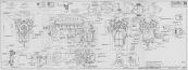
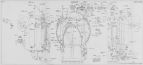
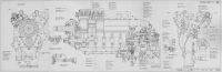
2 Aug 1940. Vincent sent Col Echols preliminary layout blueprints along with comments and explanations for the following:
PM-100 Proposed Packard Merlin propeller shaft, propeller governor and vacuum pump installation. This depicted unchanged Merlin XX construction except as follows:
The propeller shaft outer end was changed to agree with No. 50 propeller shaft detail dimensions.
The oil seal at the front clamping flange was changed to facilitate Curtiss propeller mount in accordance with suggestions given to Packard by Mr. George W. Brady or the Curtiss Propeller Division, Curtiss Wright Corporation.
He oil seal construction and the propeller shaft rear end was modified to incorporate U.S. central oil tube installation practice; the actual oil sealing parts were unaltered.
The propeller shaft vent hole was omitted so as to use the space surrounding thee tube as one of the oil passages in compliance with U.S. practice.
The front accessory drives were unchanged. A proposed vacuum pump installation was shown using a pump that had been tested in England.
The propeller governor drive and mounting pad were currently unchanged, but modification was expected to accommodate both Hamilton Standard and Curtiss governors. Brady opined that Curtiss could change its unit without much complication. Vincent was working with Hamilton Standard to determine what changes would be necessary to mount its unit.
PM-101 Proposed Packard-Merlin Generator Drive. No change was made to the U.S. generator except to lengthen the quill drive shaft. An Eclipse engineer that was consulted did not think the change would be serious. Packard provided tapped holes in the bracket so that a cover could be fitted to engines shipped without generators. This did not alter mounting conditions from existing R-R equipment.
PM-102 Proposed Packard-Merlin Fuel Pump Installation. Packard designed an adapter to fit the Merlin without change. The fuel pump shown was special only as to outlet configuration, which was necessary to obtain an installation with orderly plumbing. The R-R coupling was retained.
PM-103 Proposed Packard-Merlin Hydraulic Pump Drive.
PM-104 Proposed Packard-Merlin Gun Synchronizer and Tachometer Drives. Messrs. Barrington, J.E. Ellor and Reid, who had just arrived from the R-R factory, were surprised that synchronizing drives were being provided as they were no longer being used in England. However, Vincent assumed the Air Corps would want the equipment available. The mounting pad had not been rotated 90° as Air Corps had suggested because doing so would have required cylinder stud location changes; it had been rotated 30° and the design was submitted for Air Corps' consideration. The adapter was lengthened to overcome the interference, a change that enabled the adapter to be mounted on short studs. The R-R engineers had questioned whether this drive would be affected by camshaft vibration and suggested that a slightly-flexible drive might be required. Packard proposed mounting the tachometer drive on the inside gear on the right cylinder block, which seemed to be the best location to avoid synchronizer drive interference. While the specification required two drives, Packard suggested Air Corps accept one only in order to avoid making two kinds of adapters; the left cylinder bank pad was completely different.
The R-R engineers were adamant that 14 mm plugs should be retained and thought suitable 14 mm plugs could be obtained in the U.S. Vincent had sent a Packard drawing No. 600000 – Crankshaft blueprint as a sample of the drawings Packard proposed making for the Merlin. [Letter, Vincent to Col Echols. 86 – 88.]
3 Aug 1940. Opie Chenoweth, writing for Lt Col Edwin R. Page, Chief, Power Plant Laboratory, outlined a plan to use the 12 hand-built Packard Merlin XX engines to be constructed for experimental purposes as follows:
(1) Four engines would be allocated to Packard for whatever performance and endurance tests deemed necessary to establish its manufacturing procedures. One would probably be used for sea-level carburetor setting determination, one for general performance tests, one for durability checks and one as a spare.
(2) Eight engines would be allocated to the Air Corps as follows:
(a) One for sea level and altitude performance testing and calibration as required to obtain carburetor settings, particularly under altitude conditions.
(b) One for 150-hr type test at the Merlin X rating. This engine was to establish the base as to the Merlin's capability to pass an American 150-hr type test and was at the lower rating for this purpose.
(c) One for 150-hr type test at the Merlin XX rating if (b) was satisfactory.
(d) One for 150-hr type test at a rating between Merlin X and Merlin XX, if (b) was satisfactory. This would establish a rating a rating somewhat in excess of the Merlin X.
(e) One for a 50-hr military approval rating at a rating to be decided as a result of (b), (c) and (d).
(f) One as a spare for tests (a) through (e).
(g) One plus a spare for installation in an airplane for flight testing, possibly a Curtiss P-40.
[3 Aug 1940 Memorandum Report EXP-M-570-503-177. Plan for Use of Packard Rolls-Royce Engine. 89 – 90.]
5 Aug 1940. Maj Carroll wrote Vincent commenting on Packard's 29 Jul 1940 preliminary Merlin XX model specification No. 1025-B, as rewritten. The Engineering Division expected that the first group of hand-built engines would probably be subjected to more than one type test since there was no information about how this engine would react to an American type test; this intent was outlined in the 3 Aug 1940 Memorandum Report EXP-M-570-503-177. Since Specification No. 1025-B would have to be rewritten for production engines to include curves, proper rating and other pertinent information, the Division recommended the following different Section E-5a paragraph:
"A type test will be conducted in accordance with Specification AN-9502a, dated 30 Mar 1940, on one of the engines at the rating specified herein and based on the results of this type test a decision will be made on type testing one or more of the other engines a rating in excess of that specified.
It was obvious that the altitudes given in E-5a were not the critical altitude, that is, the altitude at full throttle for the Merlin XX, but there was no reason why the engine could not be run at these speeds and altitudes even though the throttle was not fully open. During one of Vincent's Division visits he showed charts comparing British and American type tests; the Division requested copies of these charts. The Division requested that a PESCO representative inform the Division as to their capability and willingness to manufacture the No. 207H vacuum pump in the U.S., as discussed in the Division's 29 Jul 1940 letter. [Letter, Maj Carroll to Vincent. 91 – 92.]
5 Aug 1940. Vincent reported that he had telephoned Col Page to advise him that Packard was considering the advisability of tooling up for the two-piece Merlin XX cylinder block instead of the one-piece design with which they were all familiar. Since Packard was potentially building R-R Griffons at some later date after it had been released for production, and since it had two-piece cylinder blocks, it followed that fewer tool changes would be necessary at that time if the current Merlin XX engines started out with two-piece blocks. R-R engineers Barrington and Ellor reported that the 12 engines that had been equipped with two-piece cylinder blocks had been subjected to over 2,000 hrs laboratory testing and 700 hrs testing in the air. No instance of joint leakage had been reported. While R-R did not want to dictate which construction to use, it would favor proceeding with the up-to-date two-piece construction. The new design had been created to overcome troubles that existed with the one-piece design, particularly before the saw slot was added. The new design provided for proper thermal expansion and contraction without having the saw slot and this resulted in more strength where it was needed adjacent to the seal ring. Barrington and Ellor stated that the only reason R-R was not now producing the cylinder construction was that it was unwilling to complicate its manufacturing situation during the stress of war by making changes that would affect interchangeability. The R-R representatives planned to cable R-R to make sure the factory engineering authorities approved Packard's two-piece construction. Vincent was confident such approval would be granted and recommended tooling up for the two-piece construction. Vincent thought the two-piece design would eliminate much hand work and produce a more durable cylinder block assembly. [Letter, Vincent to Col Echols. 93 – 94]
8 Aug 1940. Vincent wrote Col Echols concurring with Col Echols 5 Aug letter's multiple-type-test idea. In the interest of clear understanding, Vincent added "hand-built" before "engines." Vincent also added a second paragraph indicating the purpose of such additional type tests; he supplied copies of the revised page. [Letter, Vincent to Col Echols. 95 – 96.]
9 Aug 1940. Vincent met with Lt Col Page and Chenoweth at WF and was told that the Division had successfully installed a standard Air Corps G-9 fuel pump with inlet and outlet elbows in place on a Merlin X. Vincent was to check this same installation on a Merlin XX and provide for the use of the G-9 pump if possible. The Division had made sketches indicating a change in the right-angle hydraulic pump drive; Vincent thought this changed drive was an improvement and agreed to include it on the Merlin XX. Vincent was shown a generator drive arrangement sketch, and Chenoweth explained that a bearing would be necessary near the generator flange because of the flexible coupling in standard American generators. Vincent stated he could provide such a bearing and the standard spline in accordance with AN-9518. [16 Aug 1940 Memorandum Report EXP-M-57-503-192. Conference with Representative of Packard Motor Car Company on Technical Requirements for Packard Rolls-Royce Merlin XX Engine. 112]
10 Aug 1940. Maj Carroll wrote Vincent commenting on Vincent's 2 Aug letter covering accessory drawings.
PM-100. The Propeller Laboratory was studying this drawing and suggested that Vincent visit the Propeller Laboratory during his next WF trip to obtain comments.
PM-101. The drawing involved non-standard generator bolting arrangement, generator drive shaft lengths and splines. Since the Air Corps wanted more than one supply source, standardized accessories were imperative and the generator should conform to AN-9518. A sketch was being prepared that would permit the use of both Leece-Neville and Eclipse generators of standard dimensions. It was also necessary to move the pad on the generator adapter toward the engine's propeller end to provide sufficient clearance to install a 6" diameter generator. The current PM-101 indicated that a special generator would be required and there was question as to whether an Eclipse generator would interfere with the crankcase stud holding the generator adapter flange.
PM-102. Examination of this drawing failed to reveal why installation of a special fuel pump was necessary. Use of a standard item was very important unless there was interference on the "View of Mounting Pad Speed Rotation .600 of Crankshaft Speed" shone on drawing PM-102. Discussion of this was also suggested during Vincent's upcoming visit.
PM-103. This drawing indicated a non-standard hydraulic pump was being used, and the Air Corps thought a simpler right-angle design could be made that would accommodate a standard pump. Sketches were in preparation.
PM-104. The Armament Laboratory review was expected to provide comments within the next few days. This came on 15 Aug 1940 in a letter from Maj Carroll stating that the 30° mount pad rotation from that shown on Packard's 23 Jul 1940 sketch was satisfactory. However, the splash or gravity-fed lubrication for impulse generator parts was not. The Division requested that Packard supply lubricant to the impulse generator under pressure that did not need to be continuous. Packard's proposed single tachometer was satisfactory.
Packard's drafting procedure had been studied and a separate letter was being prepared. Inasmuch as there were several considerations that were difficult to address via correspondence, Vincent advised to bring Packard's latest Merlin XX drawings for Air Corps personnel consideration at the earliest opportunity. [Letter, Maj Carroll to Vincent. 99 – 100, 104.]
 |
 |
 |
 |
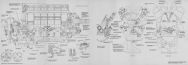 |
| These Packard-Merlin Drawings Are Representative of the Accessory Drive Specifications |
10 Aug 1940. Maj Carroll informed Vincent that the Division concurred with the drafting procedures except those portions pertaining to parts lists. Parts list were to be prepared in accordance with Specification No. 98-40103, and bills of material were to be prepared on separate forms as per Specification o. 98-40048; the two could not be combined. Maj Carroll enclosed sample bills of material and pointed out that Packard was on the Division's mailing list for all material and process specifications, and their revisions, that were listed in Bulletin No. 23; copies should be in the Packard files. Vincent concurred with the request for parts lists and bills of materials being done in accordance with Air Corps standards in a letter dated 23 Aug 1940.Packard's 4 Jan 1940 letter had requested copies of the Air Corps Standards Book and Drafting Room Manuals, which had been forwarded on 10 Jan 1940, and were signed for by Packard's Mr. Marsden Ware on 24 May 1940. [Letter, Maj Carroll to Vincent. 101]
12 Aug 1940. Following up on a 9 Aug discussion at the Division, Maj Carroll sent Vincent prints depicting one method to use standard Air Corps generators on the Merlin XX. [Letter, Maj Carroll to Vincent. 102]
Author's Note: The Packard-Merlin XX specification evolution is reminiscent of the fights between the U.S. Army Air Service and Packard in the late 1920s and early 1930s. These disagreements over definitions and standards eventually led Packard to stop producing liquid-cooled aircraft engines.
15 Aug 1940. Vincent informed Maj Carroll of several meetings that had helped choose Merlin XX accessories:
9 August – WF discussing accessory drives with Col Page, Chenoweth and several specialists from various Division departments.
13 August – Messrs. Stevens and Alexander of the British Purchasing Commission. After a thorough specification discussion, they stated that the British Purchasing Commission policy would be to cooperate in every possible way to ensure American-built and British engine interchangeability. Many engines were to go into U.S. built aircraft, which would use American propellers. They suggested starting on the basis that the British would not require special propeller shafts, having in mind that it might be necessary to make changes to some engines at a later date on engines shipped directly to England. In all probability they would want to have all their engines leave the U.S. factories equipped with gasoline pumps, electric starting equipment, and generators. In some cases they would probably also specify hydraulic pump equipment. It was their general understanding that R-R's Barrington and Ellor represented the British Purchasing Commission and that their recommendations would be accepted on all engineering matters.
15 August – Vincent met with Barrington and Ellor to discuss design details and arrive at decisions acceptable to both the U.S. Government and the British Purchasing Commission. He then outlined the joint recommendations discussed in Maj Carroll's 10 August letter:
PM-100. This drawing showed "Proposed Packard Merlin XX Propeller Shaft, also Propeller Governor and Vacuum Pump Installation." This drawing was discussed during the 9 August WF meeting with reference to the governor drive and Vincent was authorized to work with Curtiss and Hamilton Standard engineering representatives to develop governors by both companies that would be interchangeable on the R-R drive. That activity was still ongoing and Vincent was to soon report their recommendations. The propeller shaft was satisfactory.
PM-101. This "Proposed Packard Merlin Generator Drive" was thoroughly discussed at WF. Chenoweth submitted a drawing of a proposed alternate construction. Packard's revision, PM-101A, showed its second design, which had followed Chenoweth's design, but included some simplifications.
PM-102. The gasoline pump drive, as discussed at WF, was also discussed with Barrington and Ellor, who questioned the advisability of using hose connections on the fuel pump inlets and outlets. They agreed that the 12 hand-built engines should be equipped with U.S. standard pumps and connections. Drawing PM-102A depicted the fuel pump and drive as suggested by WF. PESCO had recommended the pump drive ratio be increased from 0.6:1 to approximately 0.75:1. Packard assumed no objection and proceeded with a 0.74:1 ratio as shown on the revised drawing.
PM-103. In discussion of hydraulic pump drive with Barrington and Ellor, they still wanted a provision to mount British pumps, but agreed that it might be wise to use U.S. standard units. In arriving at this conclusion, Packard and R-R had in mind that engines shipped direct to England could be equipped with British angle drives. Drawing PM-103A depicted Packard's second design of this unit; it had been necessary to change the Division design in order to provide the necessary drive ratio.
PM-104. This gun synchronizer drawing was still under review by the Armament Laboratory.
The separate letter concerning drafting room procedure was being reviewed; Packard would forward any suggestions. Packard was hopeful that the revised drawings would be approved and that it was in the position to make final specification changes for the 12 hand-built engines, and submitted the following "Experimental No. Air 1025." Packard suggested changing some of the specification paragraphs to read as follows:
C-1. Material. Materials are to be the same as specified by R-R or an American equivalent, which is to be approved by the Government. This was suggested by Stevens and Alexander on the basis that the R-R engineers would be representing the British Purchasing Commission, and, therefore, the Government. It was obvious that no changes would be submitted without approval by Barrington and Ellor.
E-17a. Spark Plugs. The R-R spark plug threaded bushings were to bee duplicated and the engine equipped with 14mm spark plugs of a type to be approved by the Government.
E-26a. Starter. The starter gear units, including provision for hand-cranking, shall be interchangeable with the corresponding R-R Merlin XX units, but minor changes were to be made in the detail parts to facilitate U.S. Production. These units together with the necessary special starter motor were to be furnished as standard equipment.
E-26d. Fuel Pump. The fuel pump mounting pad drive was to be in accordance with Specification AN-9519, dated 1 Mar 1939. The drive was to be counterclockwise at 0.74:1 of engine speed. The fuel pump was to be furnished with the engine and calibrated for the non-icing carburetor. Packard suggested that the pump be furnished with the engine because that was what R-R did and how the British Purchasing Commission specified its engines.
E-26g. Hydraulic Pump Drive. The engine was to be equipped with an angle drive unit designed to provide for mounting U.S. standard hydraulic pumps in accordance with type 2 of Specification AN-9501, dated 8 Jun 1939. Rotation direction was to be counterclockwise at 1.132:1 of engine speed.
E-26h. Tachometer Drives. One mounting pad and drive was to be furnished in accordance with Specification AN-9533, dated 1 Mar 1939. This was recommended because of the difficulty encountered in providing two drives on the R-R engine.
[Letter, Vincent to Col Echols.105 – 109.]
16 Aug 1940. Following up on his promise to Col Page during his 9 August WF visit, Vincent assembled miscellaneous Merlin XX engine data as compiled by Ellor:
"The 14 mm thread x 14 mm reach plug is used on all Merlin engines, the choice having been dictated by cylinder head design features. It is not considered desirable therefore to make any change to either the thread diameter or length of reach. High power outputs in conjunction with leaded fuels are very searching on spark plugs and have necessitated radical changes both in design and materials. Extensive development on the high-rated Merlin has proved the life of Mica plugs to be considerably reduced; the period of satisfactory operation does not exceed ten hours. As a result of intensive research on the test bed and in flight, the following three types have been developed in England and are specified for service use in the Royal Air Force.
(a) Lodge R.S. 5
(b) K.L.G. R.C. 5
(c) A.C. Sphinx S.P./502/2
The important items which have contributed to the general improvement are:
(i) Ceramic insulators.
(ii) Construction and material of the central electrode.
(iii) Elimination of gas leakage past the central electrode.
(iv) Magnitude of gas volume between insulation and plug body at the spark point.
Of the three types, the K.L.G. R.C. 5 gives the most consistent degree of reliability; A.C. 502 being second choice. Occasional have been experienced on this plug by one of more of the six electrode whiskers burning off after 50 – 100 hours running. This does not, however, upset the engine as satisfactory ignition continues with the remaining electrode whiskers. The K.L.G. follows the same lines of construction as the Lodge and differs mainly in detail and slight changes in materials. Results are not quite as consistent as either of the other two, but the modifications now being applied indicate that satisfactory results will be obtained. Particulars with test requirements and test procedures are appended."
"Attention is drawn to the fitting of flame traps on all Merlin engines, as they indirectly influence the spark plug problem. They were introduced primarily to eliminate the possibility of engine cutting out during takeoff although other advantages also accrue. A blow back past the inlet valve due to one faulty sparking plug will fire the whole of the charge in a common induction manifold if the conditions are right. Whilst the flame trap effectively prevents this, a plug may misfire continuously and produce detonation without any external indication. It is therefore essential that all plugs be 100% reliable between the agreed periods of inspection otherwise prolonged detonation may occur resulting in the burning of pistons and cylinder points. A good plug will run through a 100-hour type test without even adjusting spark gaps. Sample plugs of each type are in possession of the writer."
In connection with testing spark plugs, Mr. Ellor reports as follows:
"The type of sparking plug fully approved for the Merlin XX engine is the Lodge R.S. 5, the construction of which is shown in the attached sketch. The plug has a 14 mm thread, 14 mm reach and is capable of operating over a wide range of powers from -4 psi boost at 1,750 rpm to 15 psi boost at 3,000 rpm. The central electrode is of 0.047" diameter platinum rhodium (10% Rh), whilst the earth electrode consists of W5 nickel alloy. The insulation comprises sintered alumina with the addition of various salts for use as fluxes. Fuller details of the material construction are appended to the sketch of the R.S. 5.
Plug Testing. In order to ensure consistency in production, one plug is selected from every 2,500 produced and subjected to the following batch test.
Gas Leakage Test. Each plug is inserted in a pressure chamber which is equipped so that the plug can be raised to a temperature of 200°C and a pressure of 600 psi applied to the nose of the plug. The gas leakage should not exceed 15 cc/min when subjected to the above conditions. The temperature is measured by a thermocouple under the external seating and the gas leakage by burette. In order to obtain consistency, the plugs are tightened by a loaded spanner to a torque of 30 – 40 lb-ft.
Gas Volume. Each plug is tested for gas capacity and should record 0.3cc within ± 5°C. In order to ensure consistency of gas volume, the desired limits for the manufacture of the insulator are specified.
Spark Voltage. Each test plug has its gaps set between 0.012" and 0.015" and is tested for spark-over voltage under an air pressure of 100 psi; this should not exceed 12 KV.
Rating Test. To test the heat or preignition factor of the sparking plugs, these are finally tested in a special unit, a liquid-cooled sleeve valve engine employing a compression ratio of 7.25:1, the bore being 5.25" and the stroke being 5.00". The coolant is 100% Glycol and Silvertown P4 oil is the lubricant. These tests use 100 octane fuel. The cylinder head has been designed with the mouth of the plug towards the exhaust port. Thus, when the opening in the sleeve corresponds with the port, the plug point can be clearly seen. The plug point temperature is kept at a convenient level for optical pyrometer measurements by the use of a nickel steel insert, which enables a steep temperature gradient to be maintained between the plug nose and the seating washer throughout the successive explosive cycles. Battery ignition is used, the plugs being supplied from separate coils through their respective contact breakers, the timing of which can be varied independently of each other.
Method of Rating. The sparking plug in the inlet position is a Lock plug, which is only used for setting conditions at the beginning of the test. A K.L.G. type R.973/3 plug is generally employed for this purpose as this runs extremely cool. The plug to be rated is fitted in the exhaust position and is seated onto the insert by a phosphor-bronze washer, into which is fitted a copper-constantan thermocouple connected to a recording instrument. The unit is started up, and running on the inlet plug only the following conditions are obtained with the ignition advance set at 33° BTC:
| Speed | 3,000 rpm |
| Bmep | 180 psi |
| Boost Pressure | 14 inHgA |
| Boost Air Temperature | 100°C |
| Oil Temperatures | 80°C in, 95°C out |
| Coolant Temperatures | 83°C in, 88°C out |
Having obtained these conditions the inlet plug is switched off and the exhaust switched on with the advance set a 50° BTC. Owing to the characteristics of the unit, the power falls slightly at this advance, but the boost pressure and the above temperatures are maintained constant. When the plug seating temperature reaches 350°C and remains constant, a pyrometer of the disappearing filament type is placed in position, focused on the plug point and the temperature measured. This completes the test and the unit is shut down. The rating figure is obtained by dividing the plug point temperature by 100, e.g., a representative rating figure for a Lodge R.S. 5 plug is 8.1 which means that the plug point temperature as recorded by the pyrometer so used is 0.810°C. For K.L.G. R.C. 5 plugs, a representative rating figure is 8.5. It should be remembered that the temperatures are not scientifically correct, but enable true comparative rating figures to be obtained."
"Notes of Running of Sparking Plugs. It is essential in order to minimize the erosion of sparking plug points that a 1,000 ohm resistor be inserted in the sparking plug lead as near to the plug as possible. This damps the high-frequency oscillation following the initial discharge and reduces the RMS current value. When run on leaded fuels the following deposits have been found to occur on the sparking plug electrode and insulator.
1) Lead Bromide
2) Lead Oxide
3) Metallic Lead
4) Lead Sulfides (possible)
5) Small amounts of various metallic oxides such as iron and copper.
Under certain conditions carbon deposited from the fuel and oil can react with the above deposits, lead bromide, etc. The salient evil arising from the above is the effect of the metallic lead upon the platinum; the attack first embrittles the surface layers but if the engine is running under reduced conditions, such as when the frequently primed in winter, the attack may spread through the whole cross section. Usually the plug has completed a useful life before the penetration has become so deep as to endanger fracture of the central electrode. The Lodge R.S. 5 is considered a non-detachable plug and a life of 120 hours can be anticipated.
New Plugs – Acceptance Tests. When a new type of plug is designed, this is subjected to the type test as laid down in the A.M. Provision Specification, reference E. & I/SP.270/75 June issue. This gives the limits to which English plugs are manufactured.
Alternative Plug – Projected. A further plug is being developed by the A.C. Sphinx Company, which, it is anticipated, will give similar characteristics to the Lodge R.S. 5."
In connection with Merlin engine cooling media, Ellor reported that all lower-rated Merlins operated on 87 octane fuel were cooled by 97% Glycol. Higher-rated engines (Merlin XX) using 100 octane fuels must have water as a cooling medium with the addition of 30% Glycol to prevent freezing. This was due to difficulty in getting through a type test at the higher ratings on glycol without cracking cylinder head and leaking top joints. Numerous type tests had been successfully completed when running on water under pressure at the same temperature as Glycol. The reduction of the heat transfer coefficient due to the glycol film increased the metal temperature in the head by 50°C, and this, in conjunction with the higher pressure and temperatures incurred by the higher powers, rendered the block, pistons and valves less reliable. Adopting pressure water cooling entailed no changes to engine or installation. It was necessary, however, for the header tank, radiator and pipe connections to be constructed to withstand 30 psi working pressure and 50 psi test pressure. Glycol cooling was originally adopted to reduce radiator size due to the higher operating temperature. Pressure water cooling has the same advantage and approximately the same size radiators could be used.
In connection with the running in of production engines, Ellor reported as follows:
"I enclose a copy of our Standards Schedule for running in new engines, which applies to a two-speed supercharger engine. It is divided into two portions, light and incremental running. Light Running is carried out under its own power, in each of the two gears at speeds of 800 and 1,000 rpm, the total time being 55 minutes. This is followed by incremental running at speeds varying from 1,000 to 2,650 rpm over a period of 80 minutes. The total running in period is therefore 2 hours prior to the engine being subjected to load. The emergency conditions for running in now being adopted on Merlin engines in England is much shorter:
Light Running = 25 minutes total
Incremental Running = 36 minutes total.
I would suggest the standard practice should be adopted as a minimum."
The running in schedule referred to by Ellor appears below
Aero Test Department, Schedule No. 105, Schedule for RUNNING IN of new or overhauled Engines.
Approved for Rollsw-Royce by G. Parkin. Agreed by A.I.D. Date of Issue: 5 Jul 1940 Supersedes Issue: 12 Dec 1939
Schedule applicable to: Merlin XX Engines (pressure of Glycol cooling). Air Ministry Specification: Not Applicable.
1. Filling. Oil temperature to be approximately 50°C before filling engine systems.
2. Hot Oil Priming. The engine lubricating system is to be primed with oil of correct specification at 50°C±5°C by pumping oil into the pressure connection on the relief valve chamber. Priming is to continue during the hand turning of the engine for at least three complete crankshaft revolutions and the motoring over by the electric motor until the engine pump maintains steady pressure.
3. Light Running. With the oil and coolant at 50°C±5° approximately run at 800 rpm and light load for a period of 20 minutes in each gear. Fir a further period of 15 minutes the engine rpms to be gradually increased to 1,000 rpm in M.S. gear with minimum brake load, during which period the oil and coolant temperatures are to be increased to 65°C at the outlets.
4. Incremental Running. The engine power and speed are to be increased as follows (for 0.42:1 reduction gear ratio):
Running
Time (min) | Engine
rpm | K-1000
Brake Load (lb) | K-1200
Brake Load (lb) | S/C
Gear |
|---|
| 8 | 1,200 | 250 | 210 | FS |
| 2 | 1,000 | See X Below | | MS |
| 8 | 1,400 | 325 | 270 | MS |
| 2 | 1,200 | See X Below | | FS |
| 8 | 1,600 | 400 | 335 | FS |
| 2 | 1,400 | See X Below | | MS |
| 8 | 1,800 | 475 | 395 | MS |
| 2 | 1,600 | See X Below | | FS |
| 8 | 2,000 | 575 | 480 | FS |
| 2 | 1,800 | See X Below | | MS |
| 8 | 2,200 | 655 | 550 | MS |
| 2 | 2,000 | See X Below | | FS |
| 8 | 2,400 | 750 | 625 | FS |
| 2 | 2,200 | See X Below | | FS |
| X = Reduce Throttle Opening Only, to Obtain Speed Indicated |
On completion of the 2 minute run at 2,200 rpm the power and speed are to be gradually increased over a 10-minute period until Endurance Test Conditions are obtained. Coolant and oil temperatures are not to exceed 80°C outlet until the completion of the incremental running, after which they are to be steadily increased until Endurance Test conditions are obtained. Rapid temperature variations are to be avoided.
Endurance Test Conditions
Oil Inlet = 90°C under all conditions.
Coolant Outlet Temperature
| Condition | Water Pressure Cooling | Ethylene Glycol Cooling |
|---|
| Cruising | 100°C, tank pressure 0 psi with a 0.030" vent hole | 95°C and depression at pump inlet of 2 psi |
| Climbing | Tank pressure ≤ 15 psi, 120°C coolant outlet temperature and pump inlet pressure 3 psi less than tank pressure | 95°C and depression at pump inlet of 2 psi |
General.
(a) Vibration periods are to be avoided by altering engine speed as necessary, irrespective of the aforementioned chart.
(b) The speed of the engine must not be increased if, according to the experience of the tester, the engine is not running freely.
(c) Variations of engine conditions above the normal are to be accounted for Responsibility for failure arising from continued running under abnormal conditions rests upon the tester.
(d) Filters are to be fitted in the oil pipe line from the engine pump to the relief valve, and in the coolant outlet from the engine to tank.
At Vincent's request, Ellor prepared data comparing the standard British type test with that proposed for the first 12 hand-built American engines. Vincent quoted this report:
(1) British Type Test of the Merlin XX. This is divided into three sections.
(a) After the engine acceptance tests are completed, a whole series of calibration runs are made to establish powers and consumption under various conditions of boost pressure, speeds and mixture strengths. These tests are carried out on the Fronde dynamometer and cover a period of about 40 hours.
(b) Then follow the endurance tests at various speeds and powers carried out partly on a dynamometer and partly on airscrew.
30 hrs on the dynamometer, engine developing 850 – 900 bhp
42 hrs on the Hanger with airscrew, engine developing 950 – 1,000 bhp
31 hrs on the dynamometer, engine developing 1,000 – 1,300 bhp
(c) A repeat series of power curves are then run to check loss of performance of the endurance period. These take about 12 hours.
The engine is then stripped for examination and dimensionally checked. Details of specific tests will be outlined later, but the powers and the divided duration of running is shown on the <9 Aug 1940 graph>, plotted approximately in the sequence of running. It will be noted that the engine is subjected to the higher powers towards the end of the endurance period as this is more searching on any fatigued parts.
(2) Proposed American Type Test on 12 Hand-Made Engines. While not yet fully conversant with the American type test procedure, Vincent nevertheless took figures supplied by Olley in his note of 31 Jul 1940 and recommended to adjust the test sequence to follow the British Type Test order as shown superimposed on the 9 Aug 1940 graph (PM01 Fig. 1), with the higher powers being run at test end. This represented a comparable test, covering approximately the same total running time, all of which was to be carried out on the dynamometer. For the first 60 hours, the engine was to be subjected to a lower average power than in the British case, which included the preliminary calibration running. Vincent thought it advisable to start hand-made engine testing under easier conditions and review the position again for the production engines. Vincent also assumed the calibration would be carried out on a separate engine prior to the type test.
(3) Terminal Velocity and Dive Bombing Tests. These tests were to be carried out on the type test engine after reassembly following inspection with necessary new parts fitted.
(a) Dive Bombing Tests. 20 cycles of 1.5 minutes each in FS supercharger gear covering a speed range from 2,850 to 3,600 rpm at 9 psi boost. These were to be preceded and terminated by 15-min tests at 2,650 rpm and 71 psia.
(b) Terminal Velocity Test. 10 minutes continuous running in FS supercharger gear at 3,600 rpm and not more than 178 bhp.
This test series was to be followed by strip and inspection. Discussions were under way with the British Air Ministry to revise these tests in view of the fact that all engines now operated with constant speed airscrews having sufficient pitch range to prevent Overspeeding in a dive. Vincent suggested that WF might want to become involved in this matter.
(4) 50 Hours Full Economy Test. This test was regarded as part of the official type test but could be carried out on a separate engine:
(a) Preliminary power curves and consumption loops.
(b) Endurance tests to be run in 10-hr non-stop periods
(i) Three 10-hr periods in MS supercharger gear ratio at 2,650 rpm and 950 bhp controls set in automatic weak mixture.
(ii) Two 10-hr periods in FS supercharger gear ratio at 2,650 rpm and 880 bhp
(c) Final power curves, engine stripped for examination.
[Letter, Vincent to Col Echols. 115 – 127.]