Selected Early Engines W
Walter, Warner, Wells-Adams, Werner & Pfleiderer,
Western
Willis-DePalma, Winterthur,
Wolseley, Wright Brothers, Wright Aero
Compiled by Kimble D. McCutcheon
Published 10 Jul 2023; Revised 28 Aug 2023
Wright Aeronautical Corporation
Corporate Overview
During WWI, the Simplex Automobile Company obtained manufacturing rights to the Birkigt patents and Hispano-Suiza aircraft engine designs. The original Wright company, the Simplex Automobile Company (whose stock had been purchased by a syndicate in 1915) and the Glenn L. Martin Company of Los Angeles, California merged in 1916 to form the Wright-Martin Company. Wright-Martin manufactured Hispano-Suiza engines on Government contracts in the former Simplex Automobile plant at New Brunswick, New Jersey under the engineering direction of Henry M. Crane. The Wright-Martin company was instrumental in bringing together several individuals who would have a profound impact on aircraft engines for the next 25 years. These included Frederick B. Rentschler, George J. Mead and Andrew W. Willgoos, all of whom would be essential to the formation of Pratt & Whitney Aircraft in 1925. Early in 1920, the Wright-Martin Company was dissolved, the majority of its stock was redeemed and the balance used to financing the Wright Aeronautical Corporation (hereinafter WAC), which moved to a plant in Paterson, New Jersey under the leadership of Rentschler, its president. WAC was the centralized point of aircraft engine development and manufacturing for the later Curtiss-Wright organization, of which it was a part. The engine division of the Curtiss Aeroplane and Motor Corporation moved from Buffalo, New York during 1930 and merged with the Wright organization.
Water-Cooled Engines
For a time, WAC continued to produce Hispano-Suiza designs known as the Wright models I, E, and H; these engines featured many improvements over the original French designs, many from George Mead's fertile mind.
|
|
| WAC Model E (NARA, A39) | |
The development of the Model E engine series was done largely at the behest of the Navy Department with a view toward obtaining greater reliability and longer life. By 1923, a Model E-4 had passed a 300-hr full-throttle test at a much higher power than previously obtained without a major failure; this when the time between overhauls was typically around 100 hours. Principal changes made in the cylinder included open-end sleeves or liners that were fitted into the aluminum block, and the valves seating upon aluminum-bronze valve seats that were shrunk into the cylinder head.
When Henry M. Crane retired, George Mead became chief engineer and led WAC in the development of original designs. These included a water-cooled vertical six for dirigible use and a water-cooled V-12 for heavy-duty use in Navy three-purpose patrol aircraft.
 |
 |
 |
 |
 |
| WAC D-1 (NARA) | WAC D-1 (A39) | |||
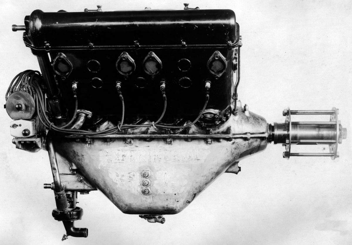
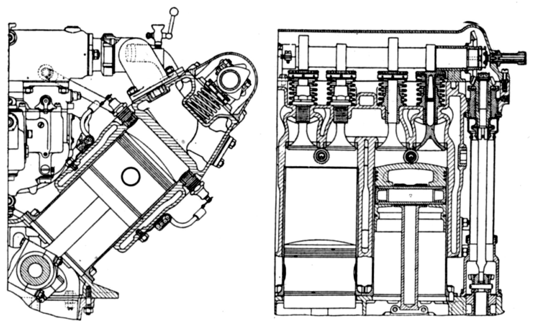
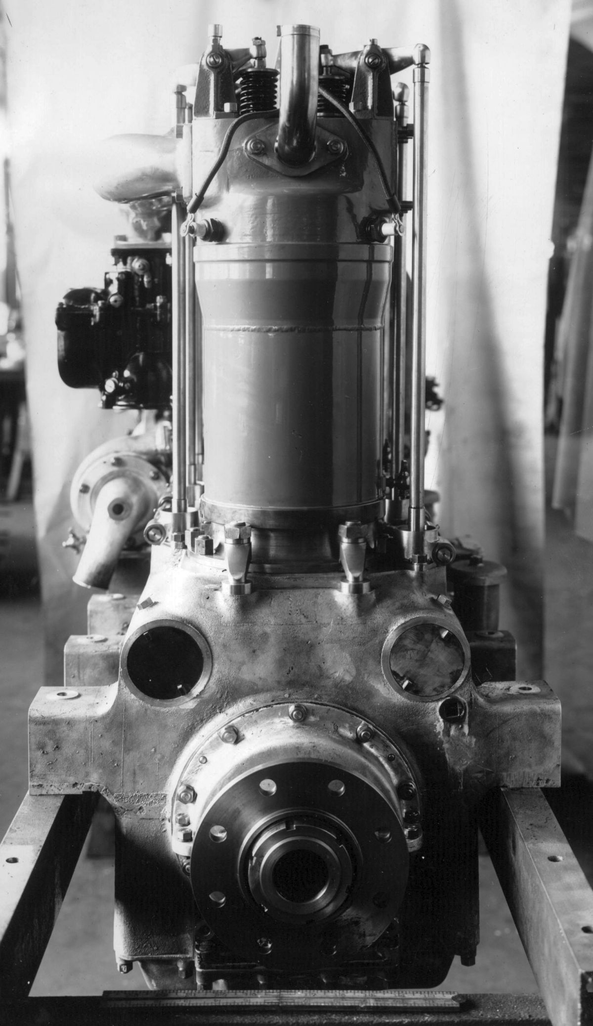
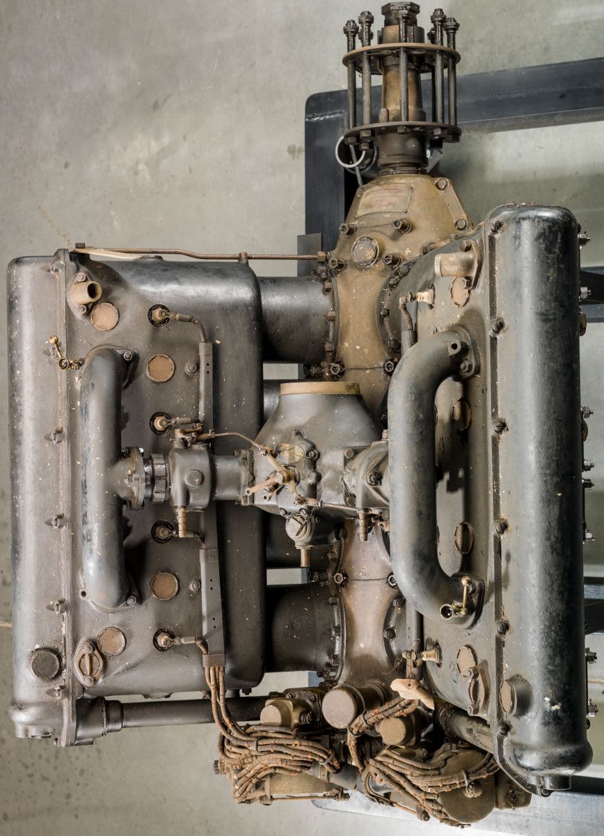
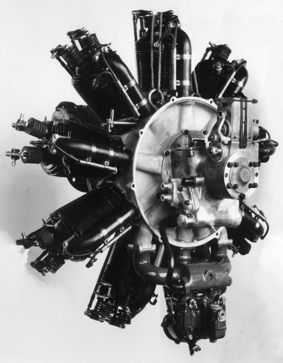
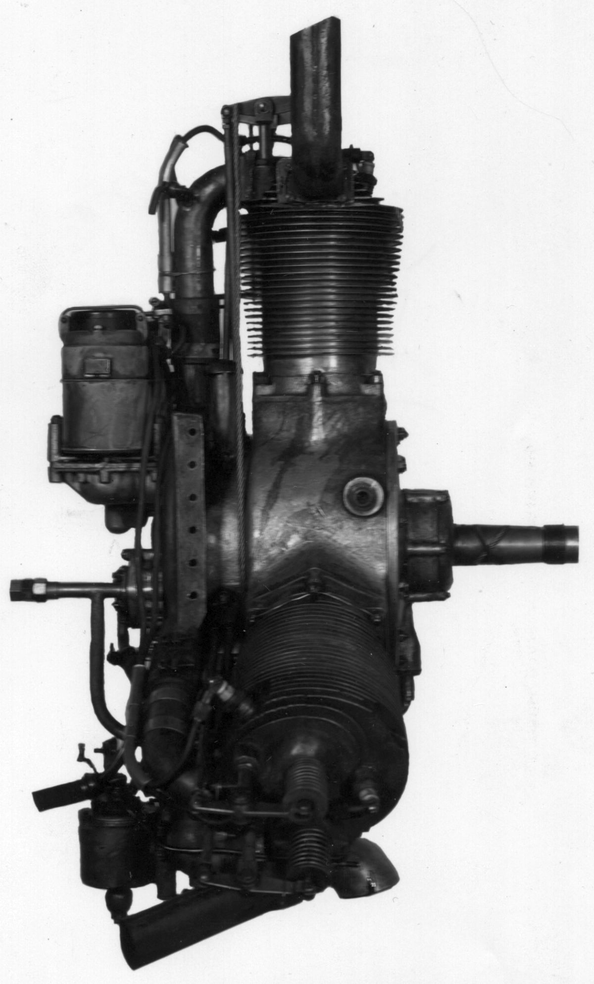
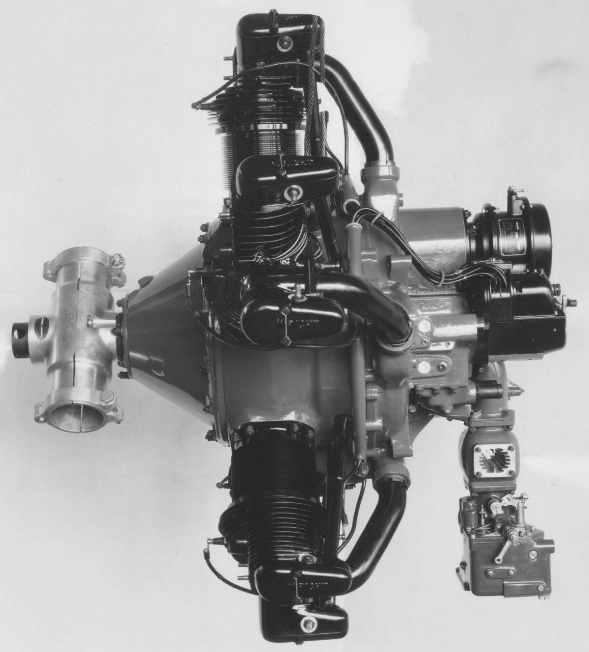
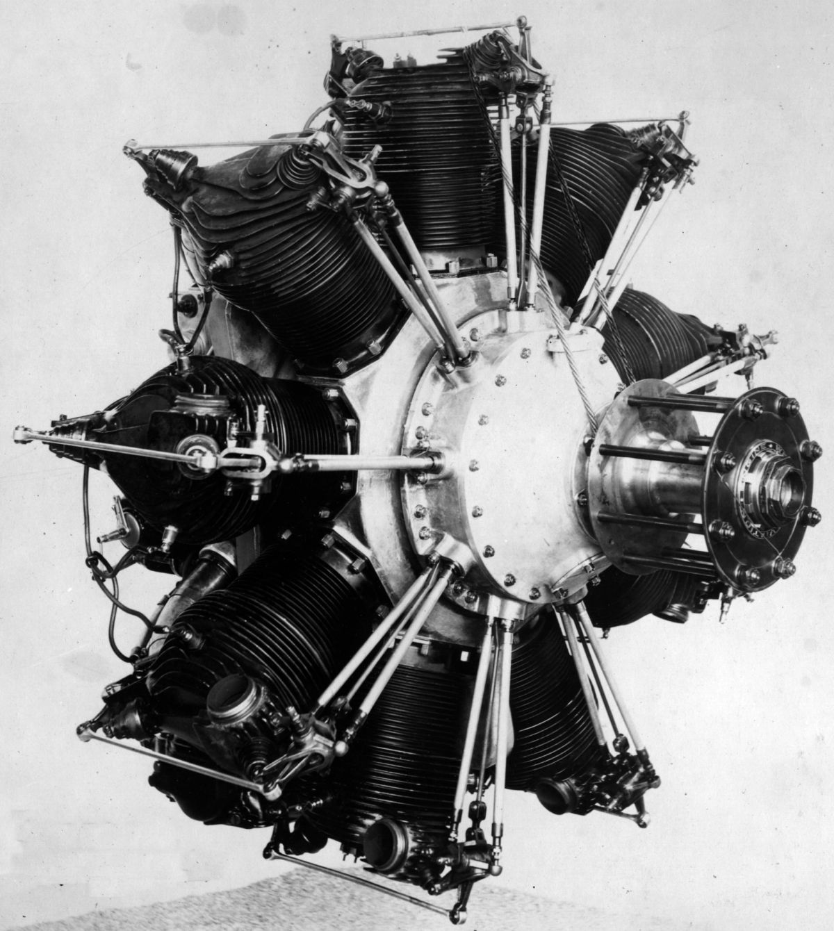
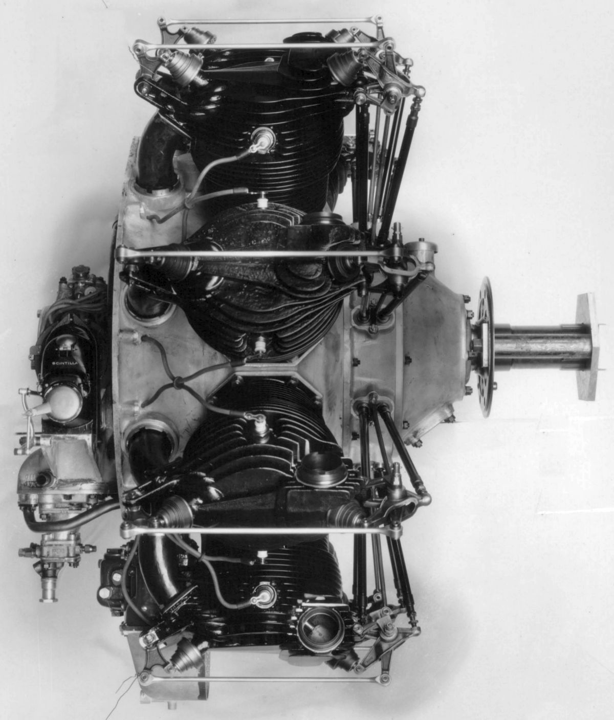
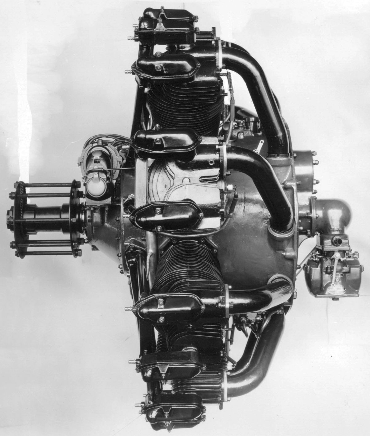
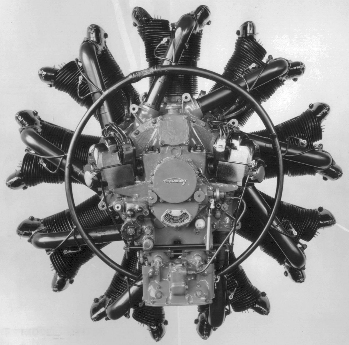
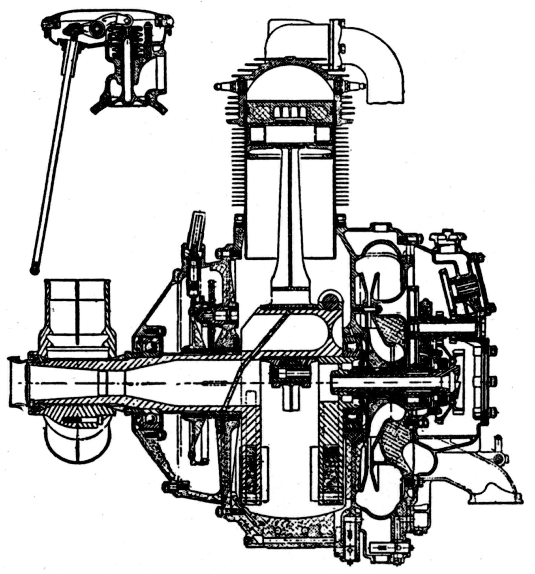
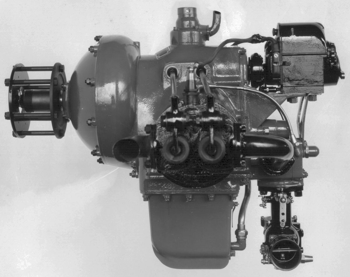
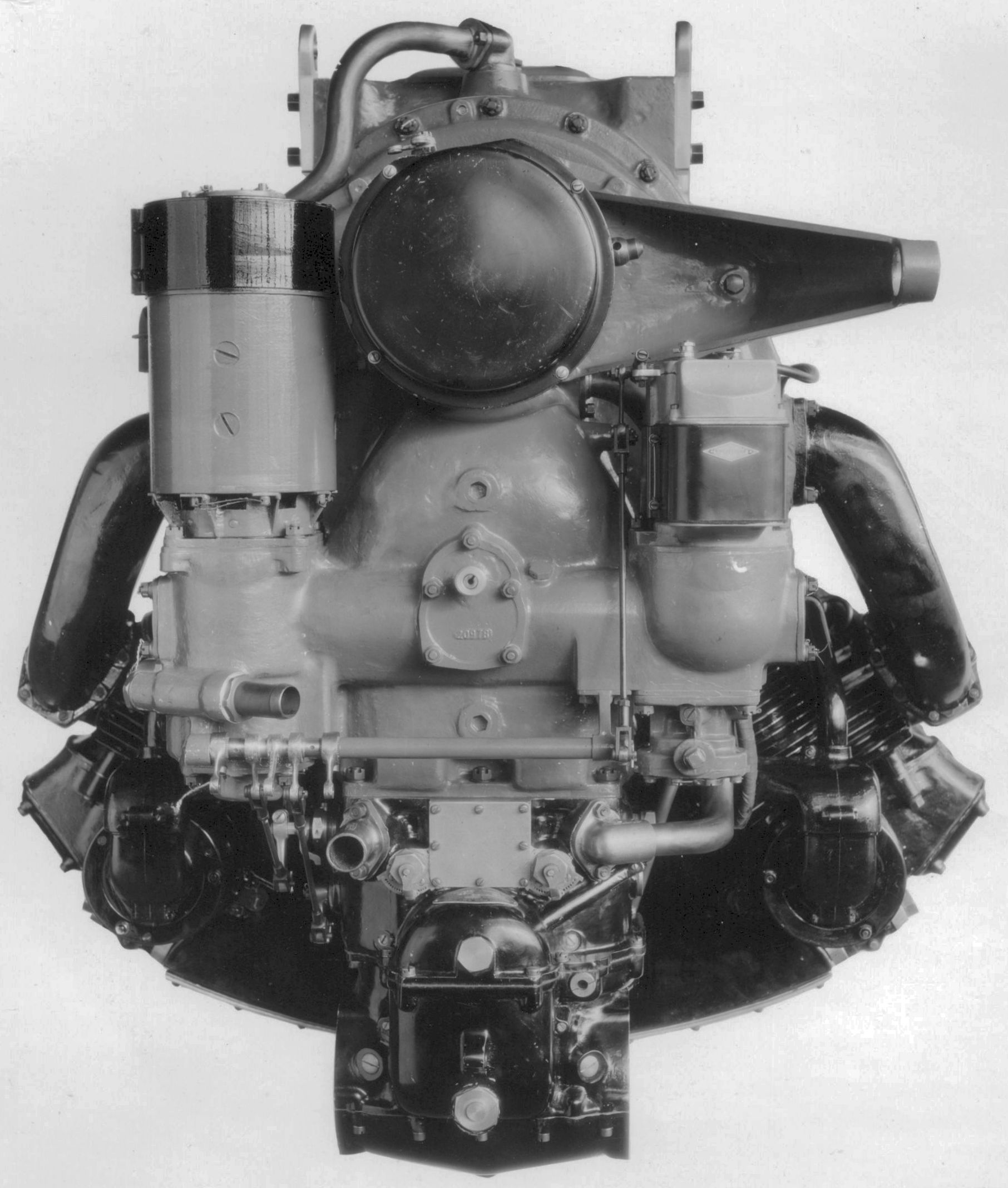
The Model D-1 was a water-cooled direct-drive vertical six with a 7.000" (177.8 mm) bore, 8.000" (203.2 mm) stroke, 1,847.26 in³ (30.271 l) displacement and 5.5:1 compression ratio that developed 350 hp at 1,350 rpm and 405 hp at 1,400 rpm. Fuel and oil consumptions were 0.475 and 0.008 lb/hp/hr. Dry weight, without propeller hub, generator, or starter, was 1,320 lb (599 kg), length was 71.0625" (1,780 mm), width was 22.3125" (592 mm), and height was 41.1875" (1,046 mm)
The D-1 completed a 50-hr endurance test in March 1922 after the Navy Department had ordered three engines in June 1921. Designed for airship use, it was the largest of its type built up to that time. The individual cylinders loosely followed Maybach dirigible engine designs used in Zeppelin airships. The cylinder head was an iron casting into which a steel barrel was screwed and welded, both members surrounded by a welded-on sheet-steel water jacket. Four vertical valves on the cylinder head were operated in pairs by rocker arms supported in brackets bolted to each cylinder top. The rocker arms were actuated via push rods and camshafts on each side of the upper crankcase. The mixture was supplied by two Stromberg carburetors, each attached to a manifold connecting three cylinders. The cast-aluminum pistons were fitted with full-floating piston pins. The connecting rods had tubular shanks. The 3" (76.2 mm) diameter crankshaft journals were carried in plain bearings supported by caps attached to the aluminum alloy upper crankcase. The lower aluminum alloy crankcase was just an oil pan. The main bearing supports were box-shaped sections through which air was forced to cool the bearings. The oil pump gears, oil filter screen, and pressure relief valves were located at the engine rear, along with two Splitdorf magnetos driven by a cross shaft with advance control. Located between the magnetos was a booster magneto for starting. All engine controls were placed on a small panel at the rear so that the operator would not he required to move about. The water pump, engine speed governor, and corresponding oil-pressure governor were located at the side of the engine above the engine beds, thereby permitting ordinary repairs being made without removing the engine from the gondola.
 |
 |
 |
 |
 |
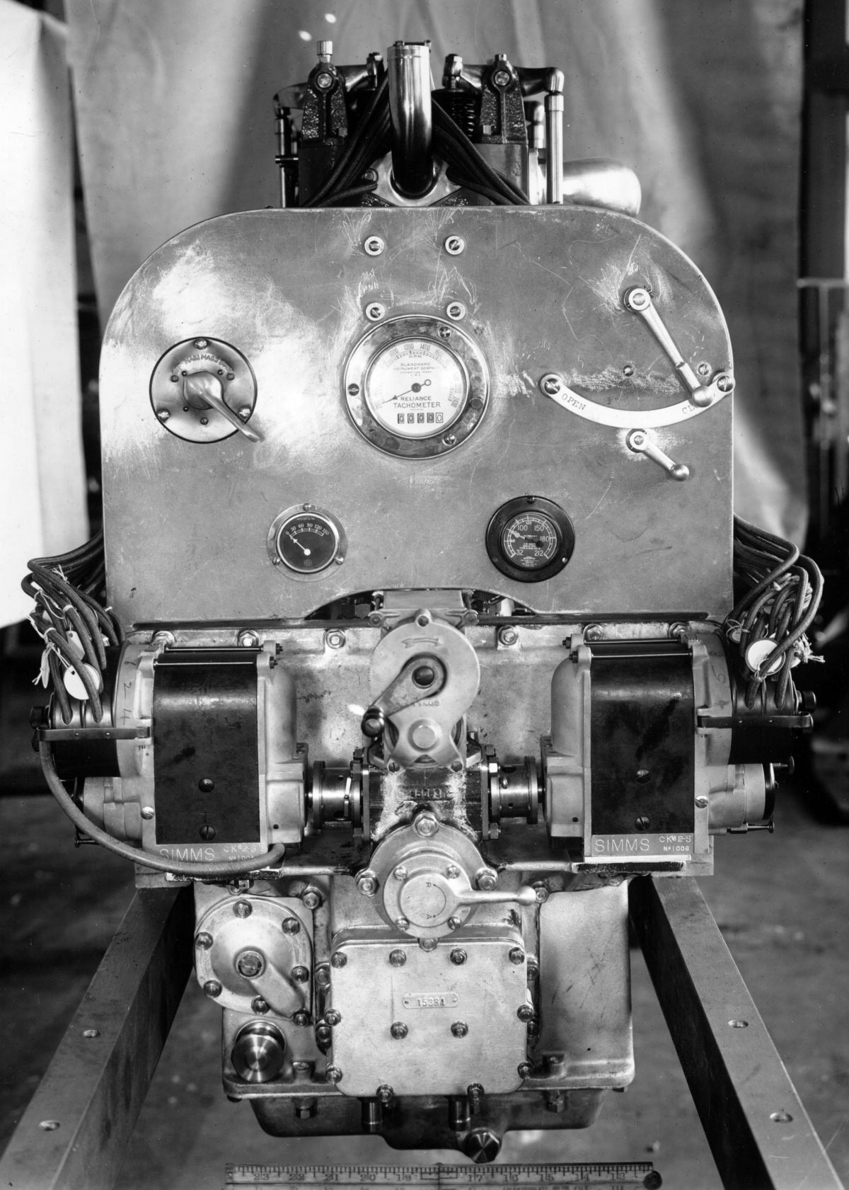
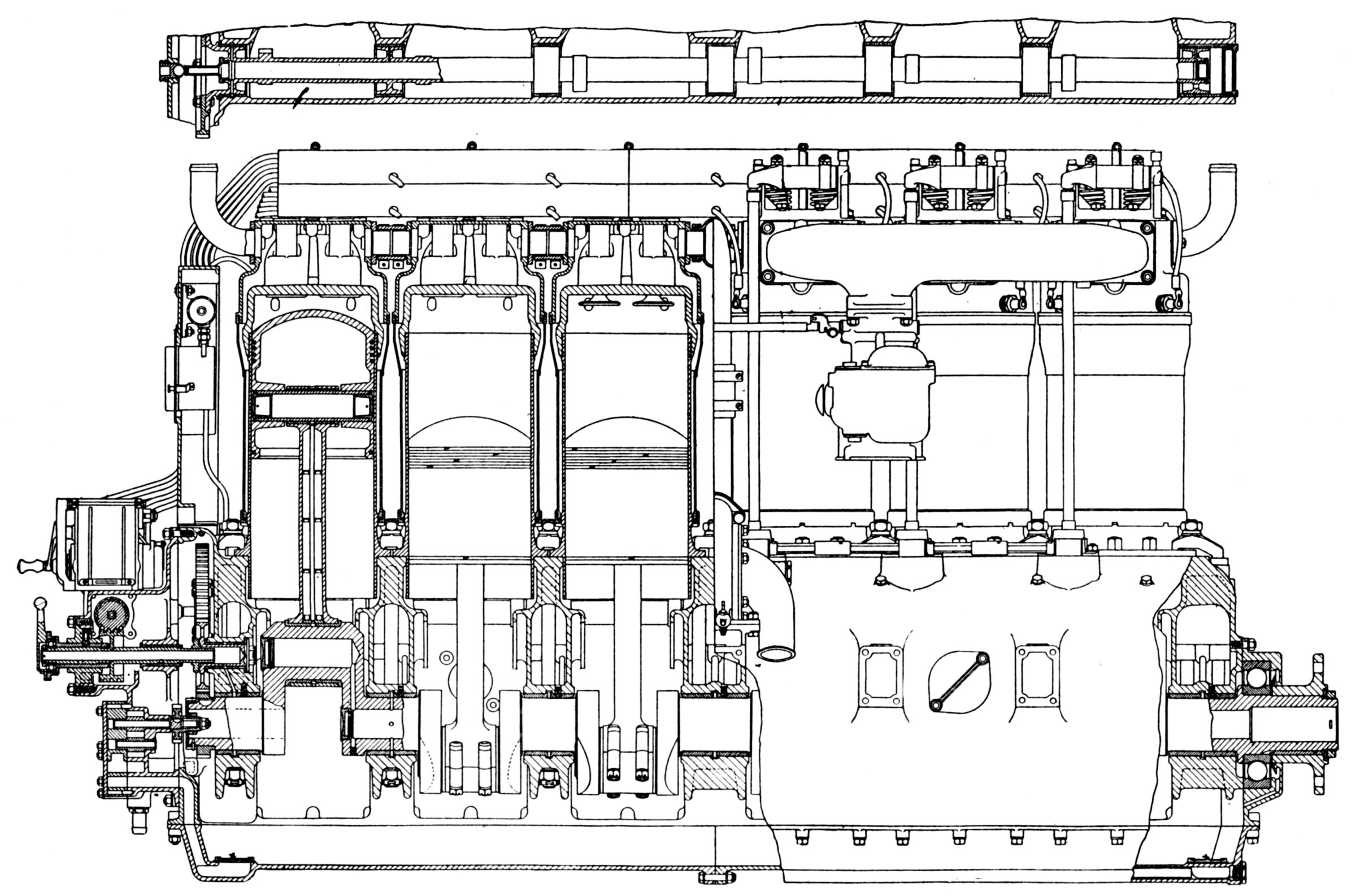
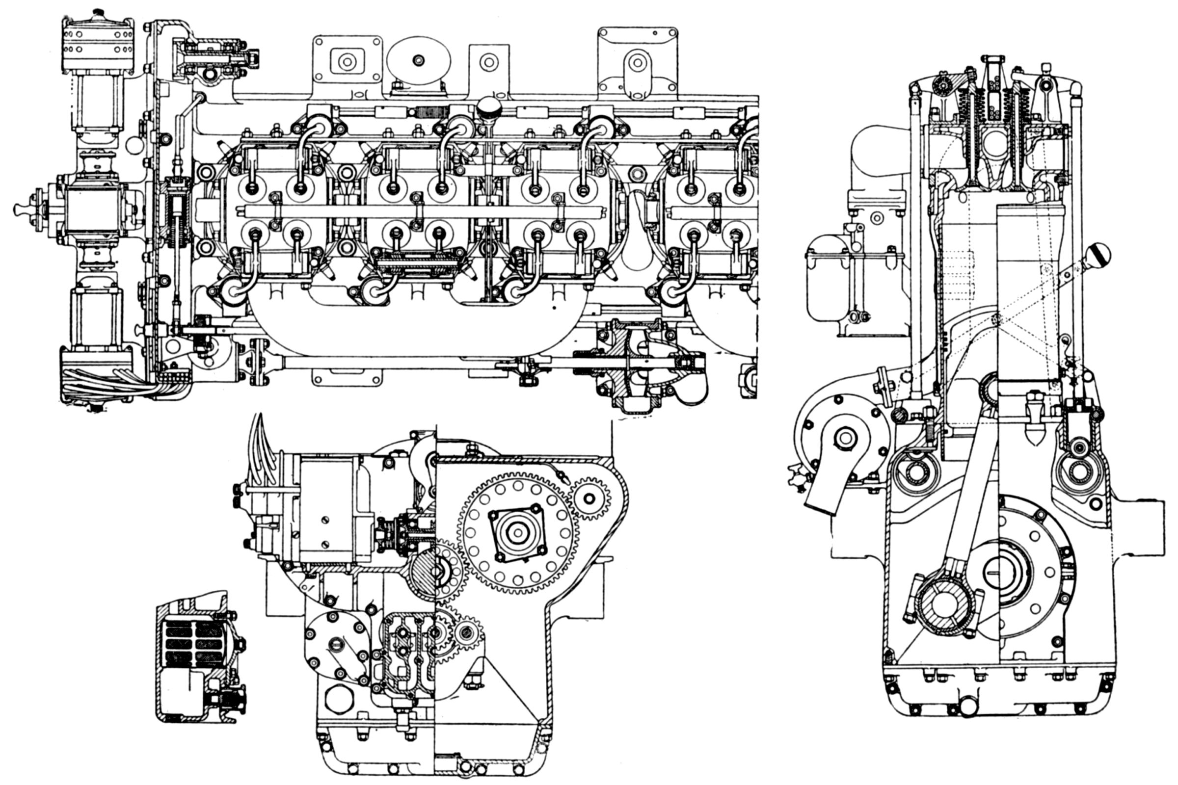
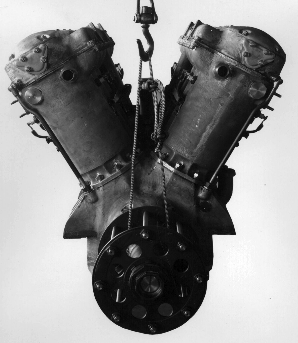
| WAC T-2 (NARA) | WAC T-2 (A39) | |||
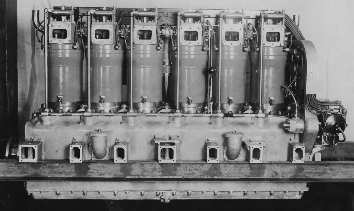
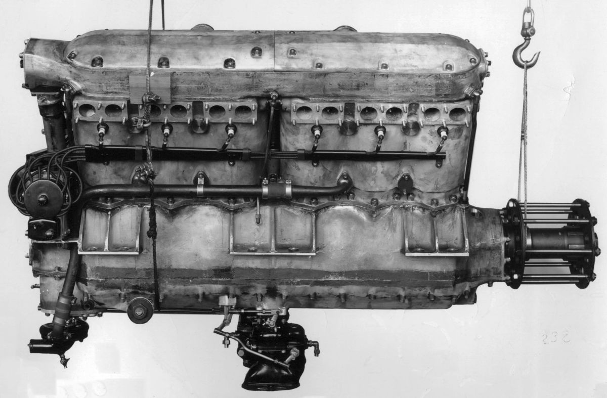
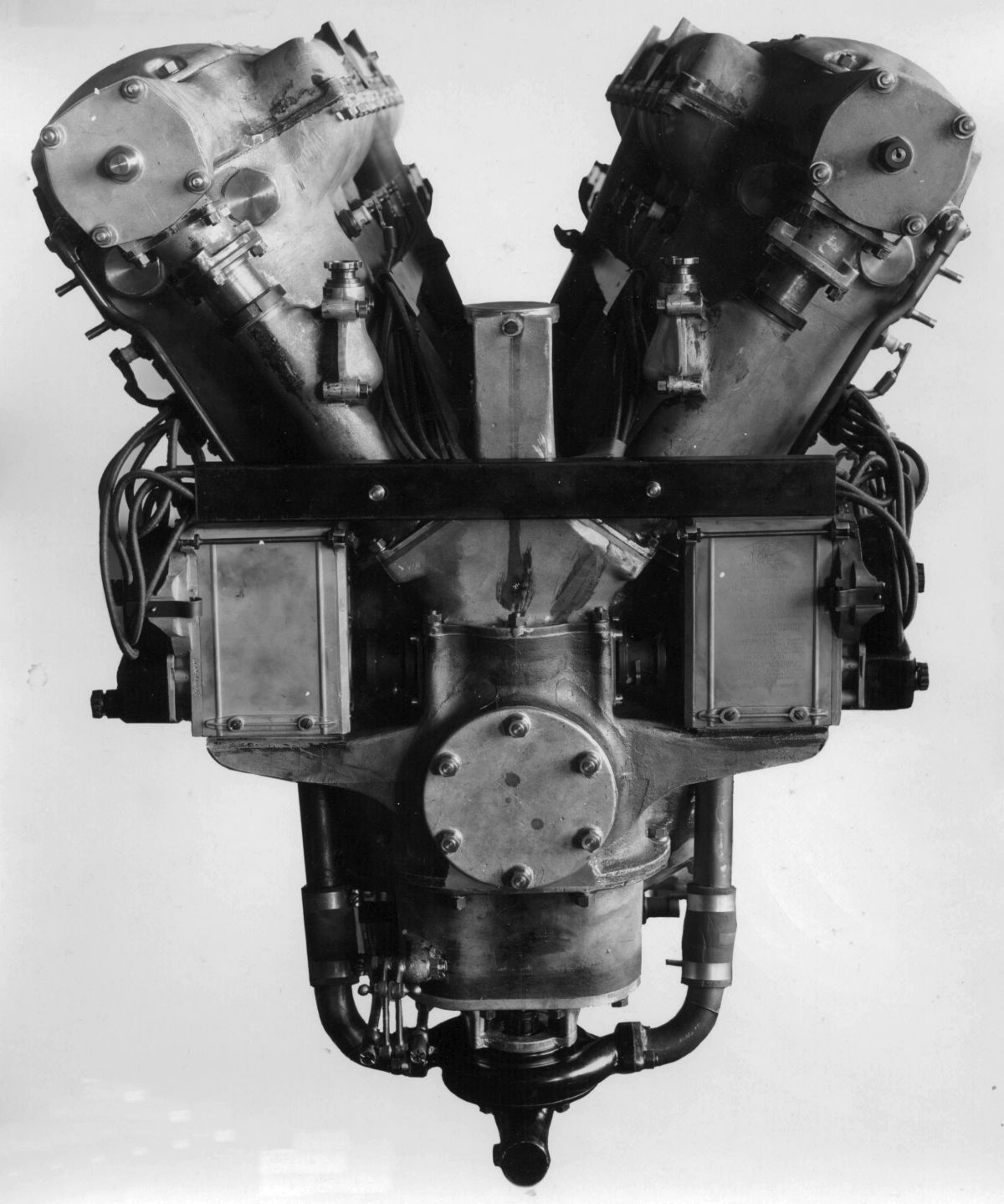
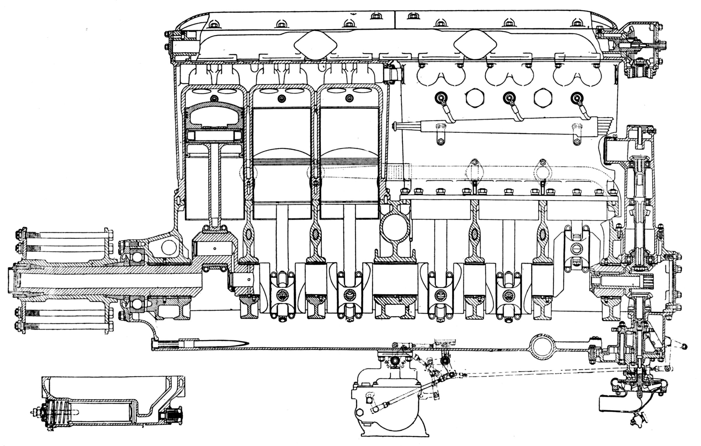
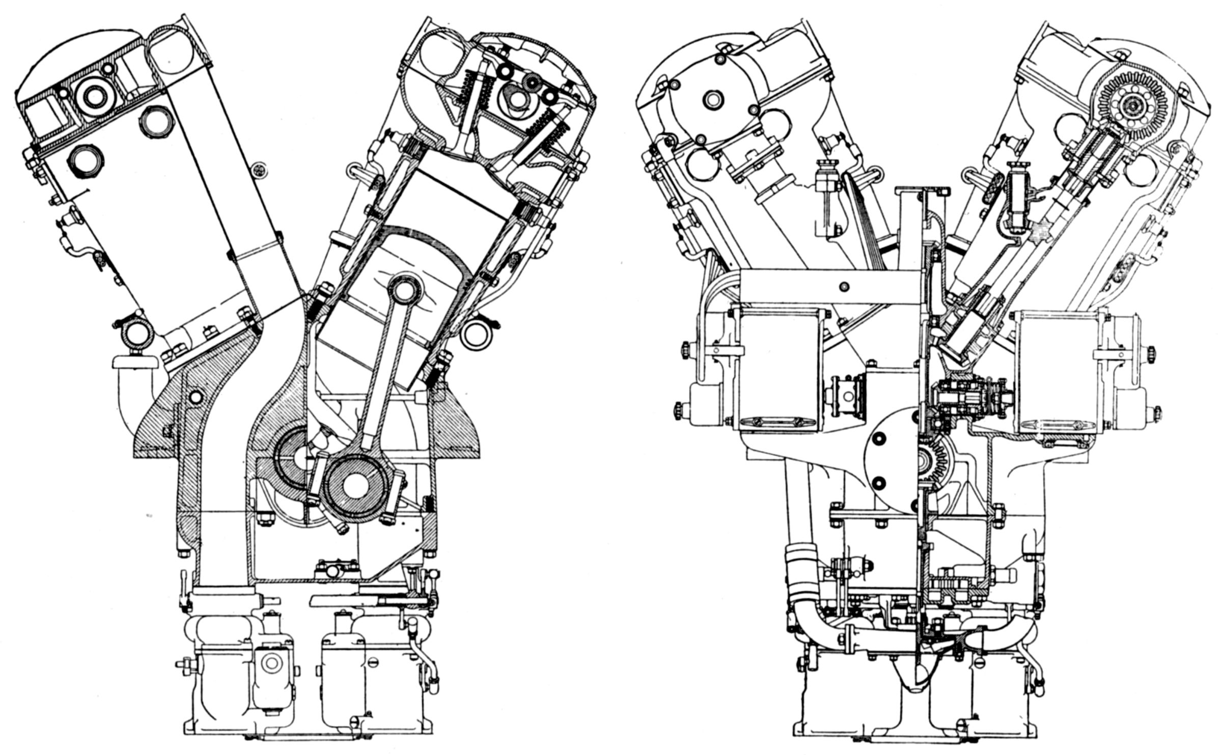
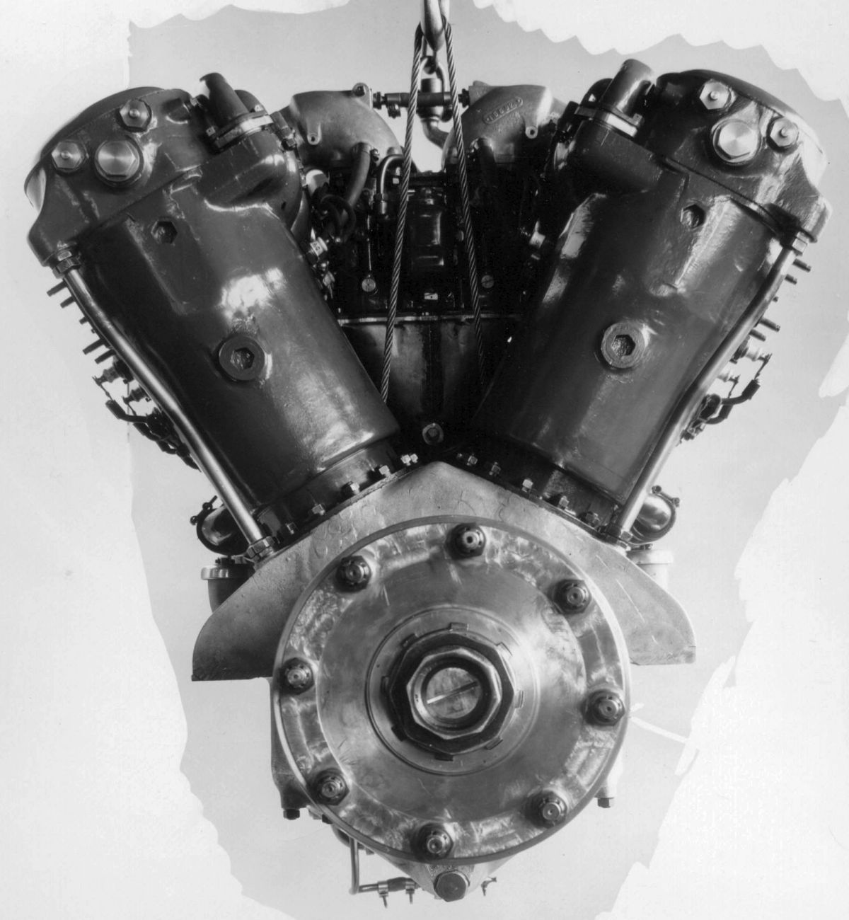
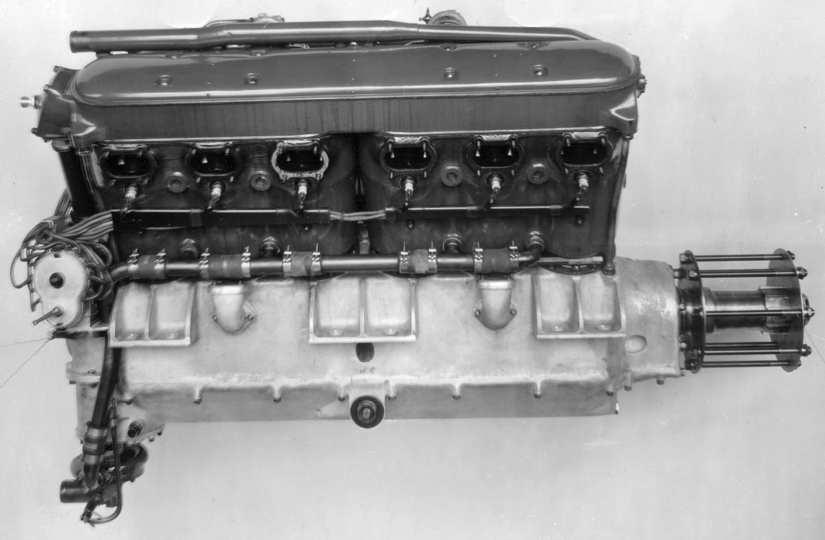
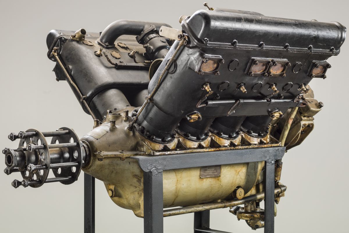
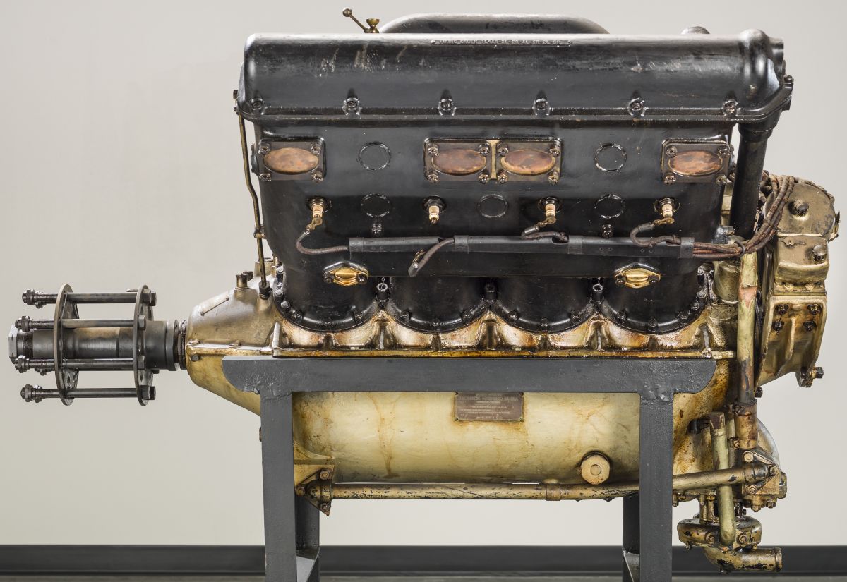
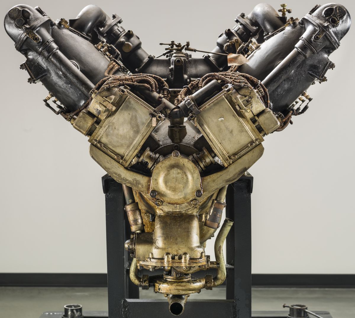
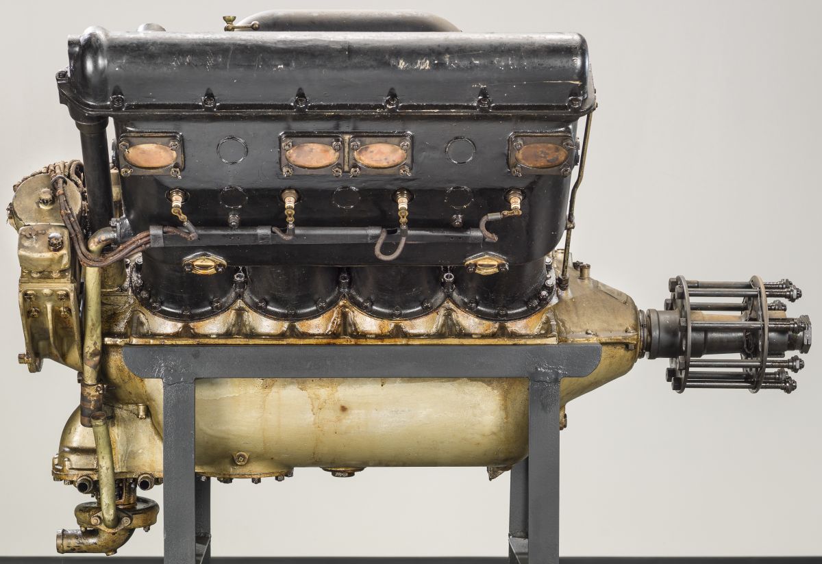
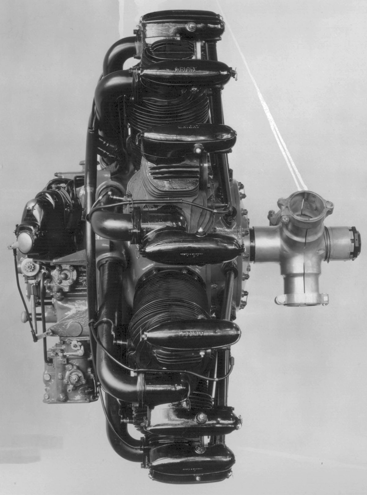
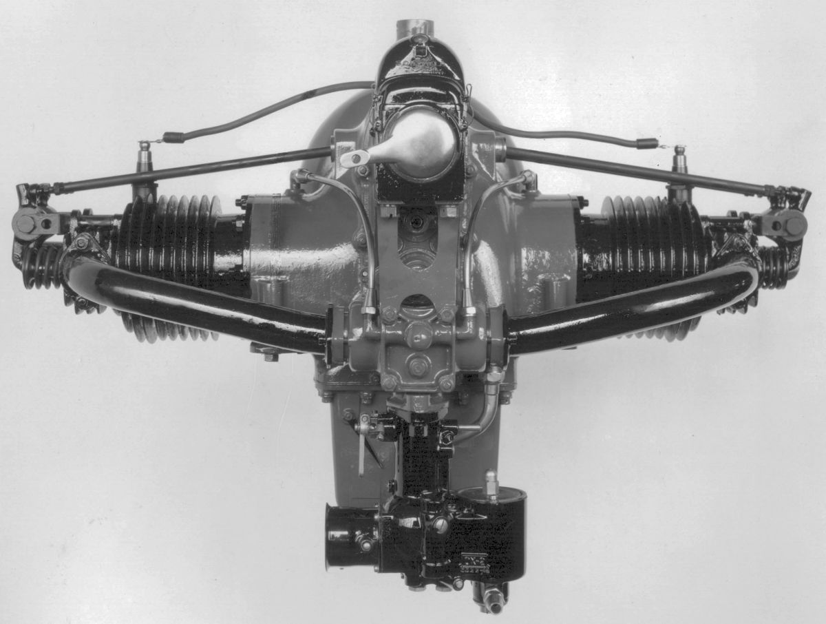
The Wright T-2 was designed and built for the Navy Department for large Navy seaplanes. Navy desired an engine approximately the same size and weight as the Liberty L-12, but with greater power, so it could be substituted in airplanes originally designed for the L-12. The T-2 was accepted by the Navy Department early in 1922 after it had successfully passed an official 50-hr test. The T-2 model was a water-cooled 60° V-12 with a 5.750" (146.05 mm) bore, 6.250" (158.75 mm) stroke, 1947.54 in³ (31.915 k) displacement and 5.5:1 compression ratio that was rated 500 hp at 1,800 rpm. Fuel and oil consumptions were 0.48 and 0.02 lb/hp/hr. The aluminum alloy cylinders were cast in blocks of three and fitted with shrunk-in open-ended steel liners. Aluminum-bronze valve seats and spark-plug bushings were installed. Each cylinder's four valves were inclined at a small angle to the cylinder axis and were actuated by rocker arms from a single camshaft in a housing attached to the six heads of each cylinder bank. The rocker arms ran on light steel tubes whose axes were parallel with the camshaft; they could be withdrawn for rocker arm removal. These tubes carried oil under pressure that lubricated the entire valve mechanism. The cam housing had a removable cover to access screws in the rocker arm ends for valve adjustment. The inlet manifolds were cast integral with the cam housing and designed so that the carburetors could be located either in the Vee or below the crankcase. The aluminum alloy pistons were fitted with three compression rings above the piston pin, and one oil-scraper ring on the piston skirt. The piston pins were full floating with bronze end plugs to prevent cylinder wall scoring. The fork-and-blade connecting rods had tubular shanks and the forked rod held a special bronze bearing sleeve, the inner rod bearing directly upon this sleeve, and the sleeve itself bearing directly upon the crank pin. The crankshaft had seven plain bearings for its 3" diameter journals. A deep-groove radial ball bearing resolved propeller thrust. The crankshaft main bearings were supported by bearing caps attached to the cast aluminum alloy crankcase upper section; the lower section served only as an oil pan.
The magneto, camshaft, oil and water pump, and gun synchronizer drives were arranged at the engine rear. Provision also existed for driving a generator or fuel pump, and either a hand or electric starter could be mounted on the engine rear. The two SS12 Splitdorf magnetos delivering dual ignition were mounted on brackets with axes at right angles to the engine centerline. Two Stromberg carburetors supplied the mixture. A double-outlet water pump, located at the engine lower rear, delivered water through pipes to two connections on each cylinder block's lower side; water left the jackets through connections at the cylinder block upper ends. The dry-sump pressure-fed lubricating system used gear pumps being used. Oil from the pressure pump passed through a large cylindrical strainer before being led to the bearings under a pressure of approximately 75 psi.
 |
 |
 |
| WAC T-3 (NARA) | ||
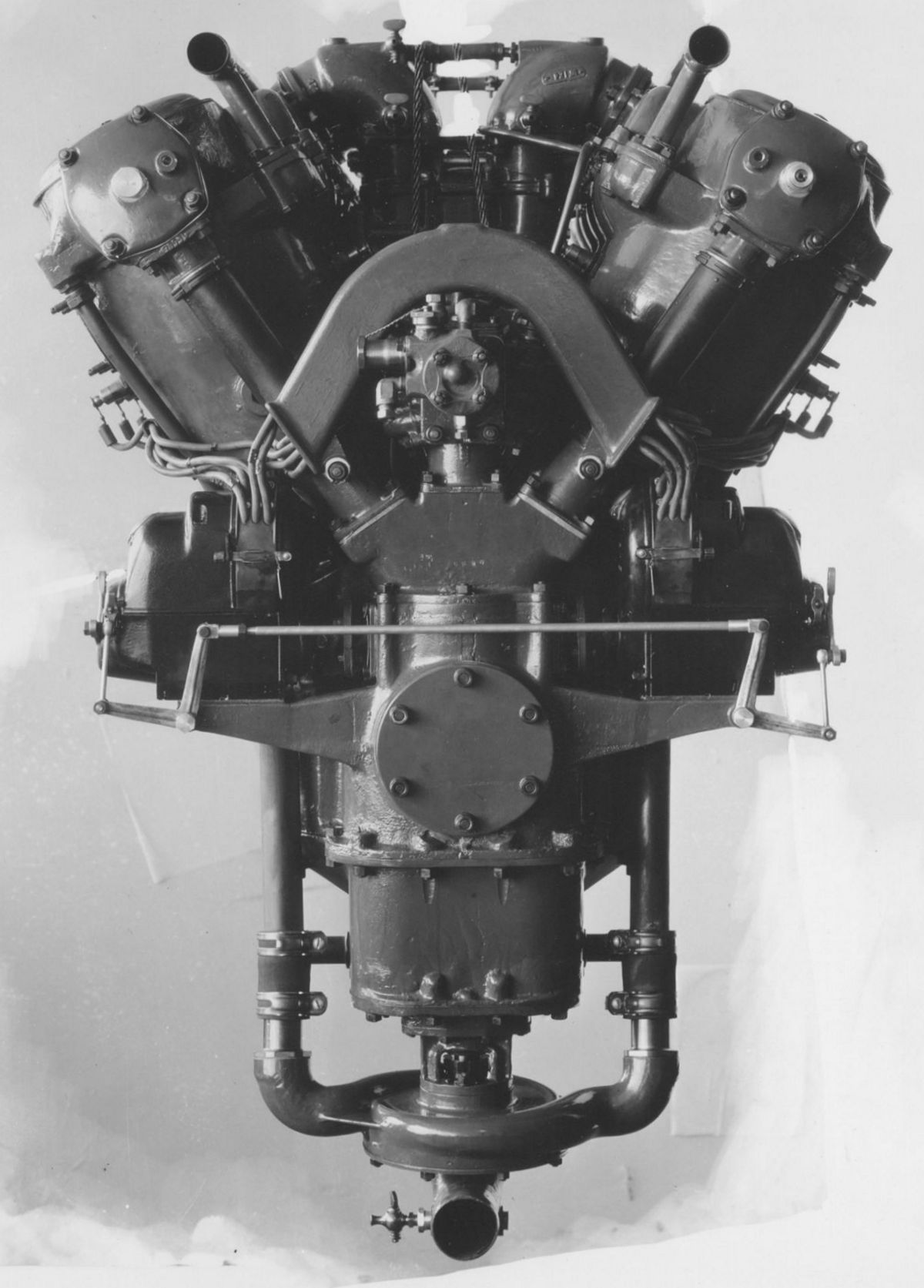
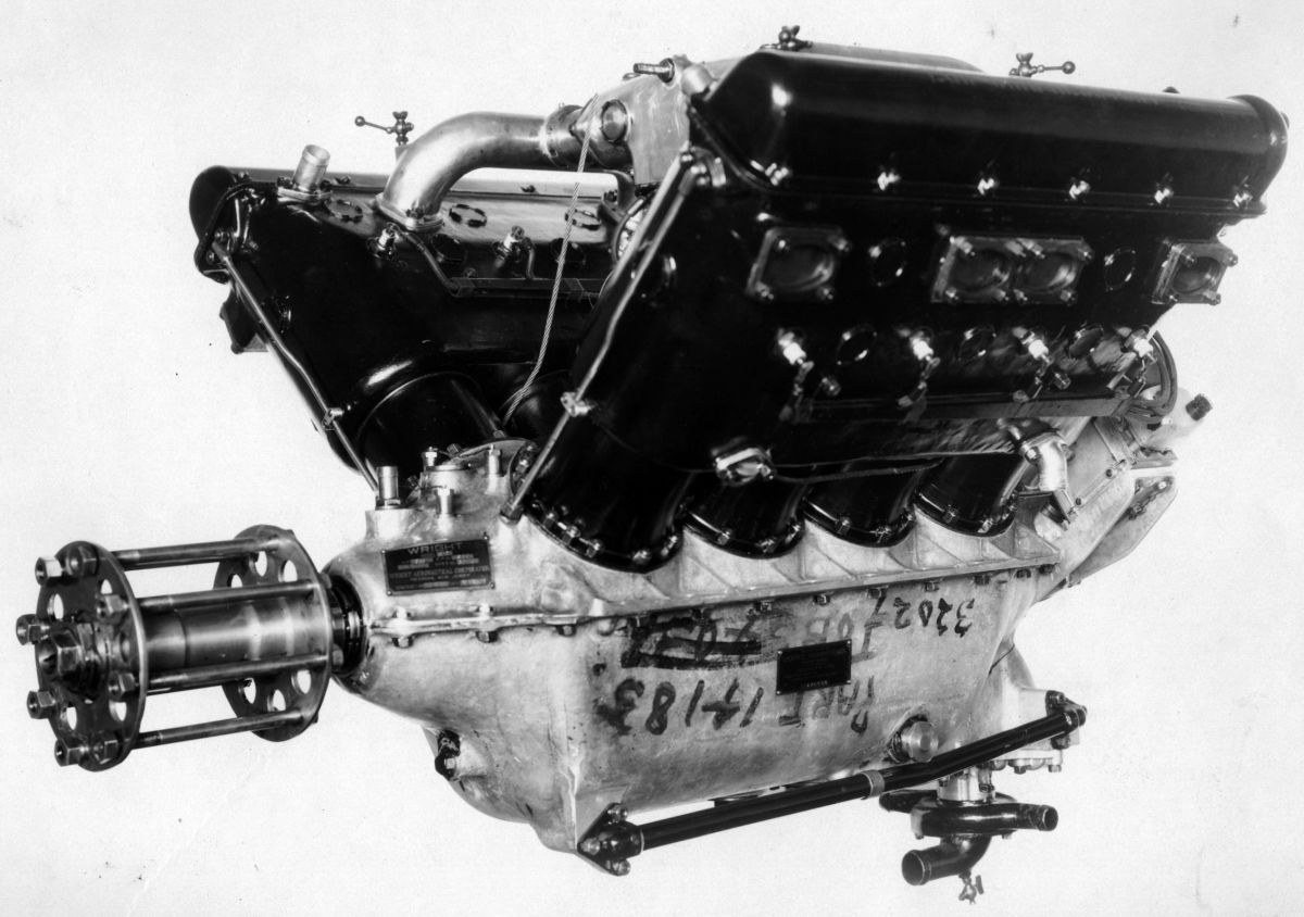
The Wright T-3, introduced in 1923, differed from the T-2 only in detail. When the names of winds were later adopted to identify Wright engines, the T-3 became known as the Tornado. A T-3, rated from 550 to 600 hp for marine use, was named the Typhoon. The first T-3 had two power ratings. With a 5.5:1 compression ratio, the rated output was 575 hp at 1,800 rpm; with a 6.5:1 compression ratio, the rated output was 650 hp at 2,000 rpm. Dry weight was 1,150 lb (522 kg). When using a 6.5:1 compression ratio, fuel and oil consumptions, were 0.50 and 0.02 lb/hp/hr. Length was 65.625" (1,667 mm), width was 30.875" (784 mm) and height was 42.394" (1,077 mm).
The improved performance of the T-3 versus the T-2, was due to increased valve diameter and lift, enlarged inlet manifold passages, and the use of redesigned and relocated carburetors. With the carburetors located in the Vee instead of underneath, the crankshaft center main bearing was shortened. The resulting T-3 was about 5" shorter than the Liberty L-12. The crankshaft journal diameter was increased from 3.00" (76.2 mm) to 3.25" (82.55 mm), resulting more rigidity and smoother engine operation. The forged-duralumin bearing caps were held to the upper crankcase by studs instead of through bolts. Several important design changes were made in the crankcase, one of which was the use of four breathers instead of two. The T-2 had used flanges on the aluminum alloy cylinder block castings to attach the cylinders; the T-3 used flanges on the steel barrels for this purpose. As a result, the cylinder blocks were lowered and the connecting rods were slightly shortened by increasing the piston pin diameter by 0.125" (3.18 mm) to 1.375" (34.93 mm). The exhaust ports were changed from individual to siamesed form, and all valves diameters were increased by 0.25" (6.35 mm) to produce 1.875" (47.63 mm) clear diameters. Two Stromberg NA-U6T double carburetors were mounted in the Vee, with each carburetor barrel supplying three cylinders; the T-2 had used two large single-barrel carburetors. The new carburetor assembly, including air horn, piping, and control rods, could be removed as a unit. An oil gallery, bolted to the bearing caps underside, distributed oil under pressure to the main bearings instead of the cast-in gallery the T-2 had used. Oil was fed into the hollow camshaft in addition to the tubes supporting the rocker arms. Additional positive-feed oiling was provided for the gears at the engine rear. The T-3 was also built with plain spur propeller reduction gears furnished by the Allison Engineering Company, Indianapolis, Indiana. The complete geared model dry weight was 1,280 lb (581 kg), and the maximum output was 780 hp at 2,200 rpm.
During 1923, WAC offered replacement cylinders for the Liberty engine series that were constructed like those for the T-2 and T-3. The object was to eliminate rusting of the thin steel Liberty water jackets while in storage. The WAC cylinders were also more rigid because of the block construction and stiffer cam housings. The valve gear was completely enclosed, eliminating oil leaks. A power output improvement of about 10% was claimed and the engine could be operated without overhaul for a period six times longer than with the original cylinders. These new aluminum alloy Liberty cylinders were cast in blocks of three. Open-end steel liners were fitted, and aluminum-bronze spark plug bushings and valve seats were shrunk in place. The camshaft and valve gear housing was bolted to the six cylinders in a bank.
Following the WAC practice employing wind names to identify its various models, the E-4 engine, which was still being produced for aircraft use, became known as the Tempest. As last produced, it was rated 200 hp at 1,800 rpm and weighed 477 lb (216 kg). The Hurricane, an E-4 model for marine use, was rated at 200 hp. A special E-4 engine with increased bore was rated 240 hp and known as the Special Gold Cup Marine Engine.
 |
 |
 |
 |
 |
 |
 |
| Wright Model H (NARA) | Wright Model H-3 (NASM) | |||||
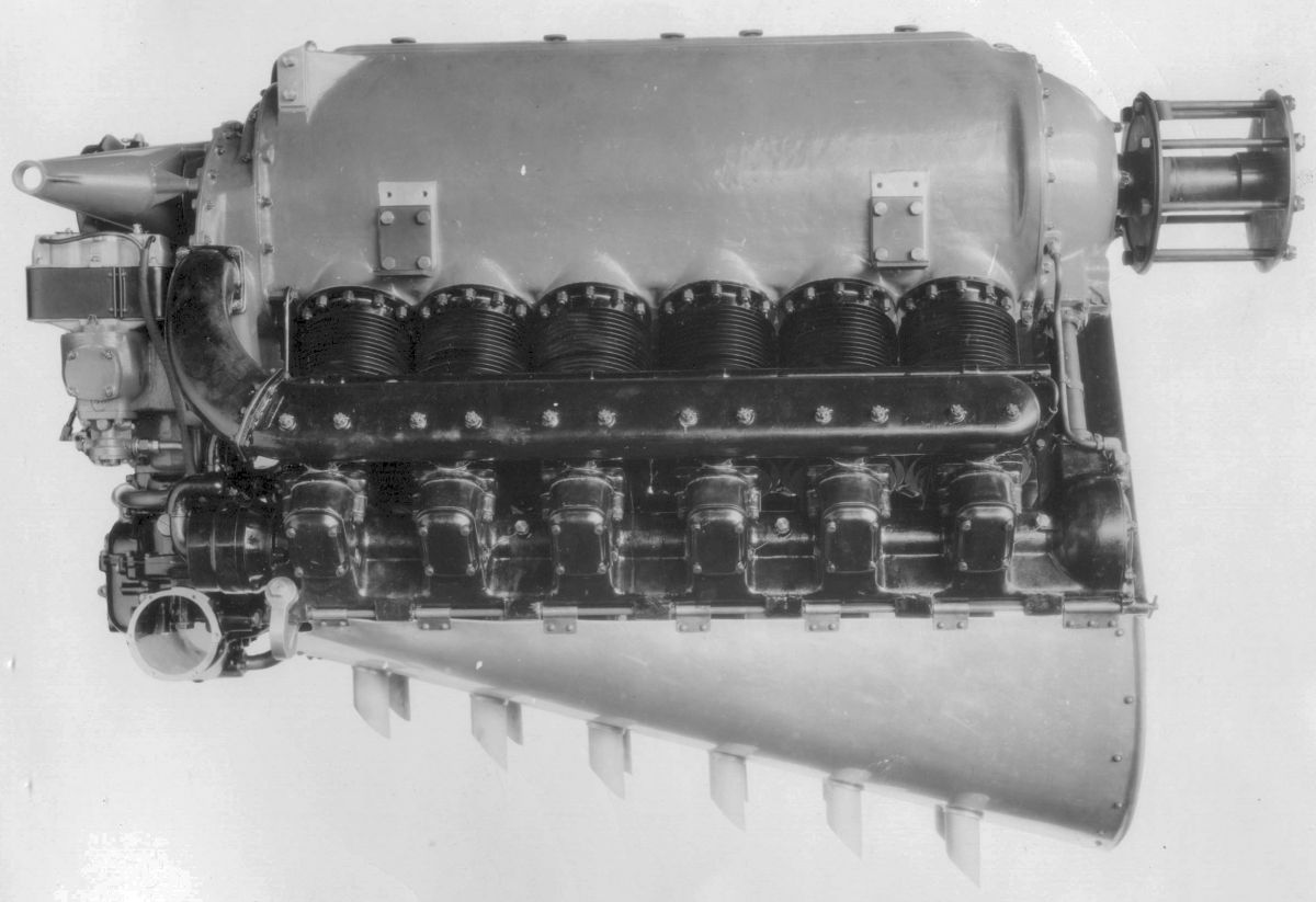
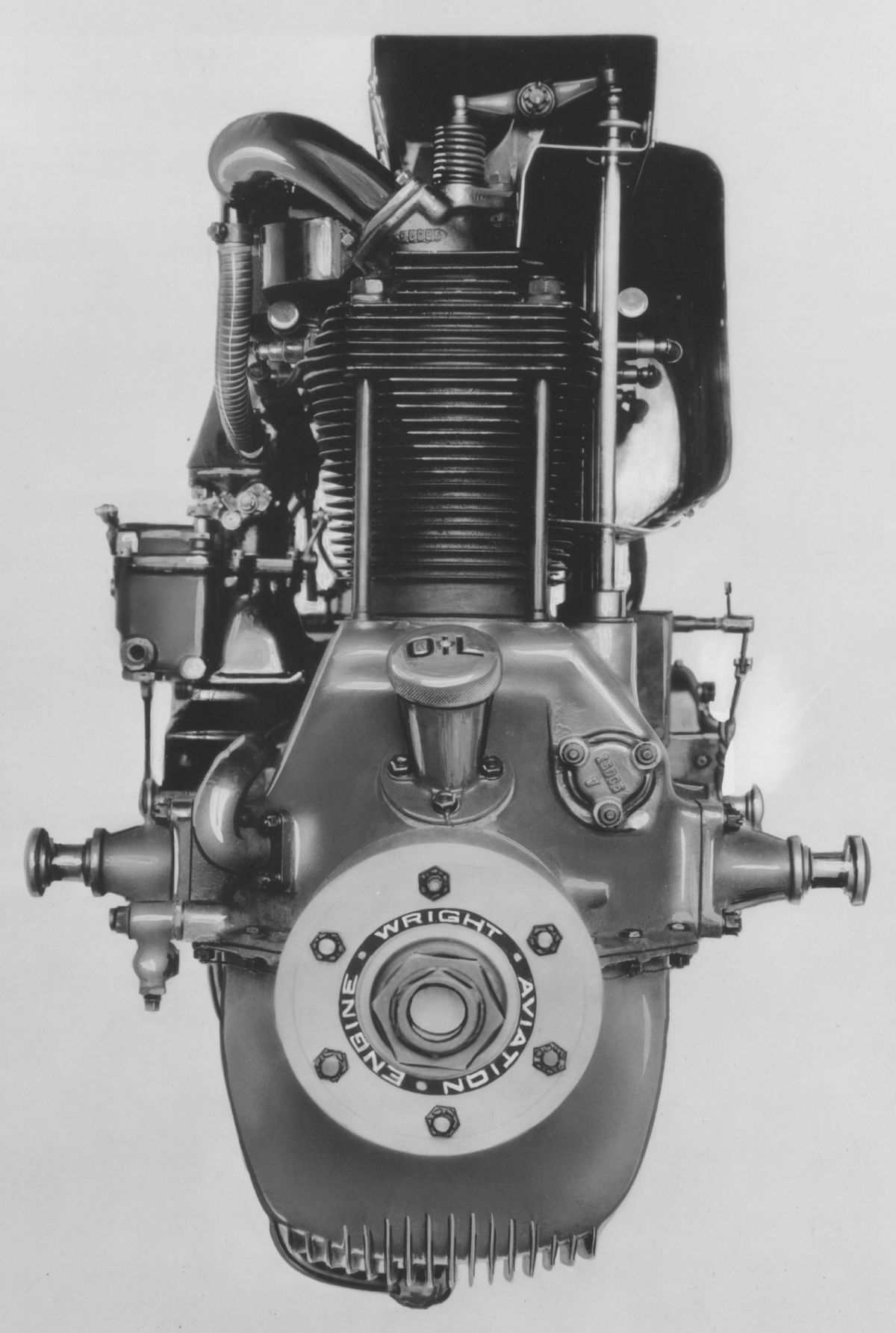
The H-3 was an improved Model H engine with a 140 mm (5.518") bore, 150 mm (5.906") stroke, 18.473 l (1,127.27 in³) displacement and 6.0:1 compression ratio that produced 375 hp at 2,000 rpm and 400 hp at 2,100 rpm. Fuel and oil consumptions were 0.52 and 0.02 lb/hp/hr. Dry weight was 624 lb (283 kg).
Air-Cooled Engines
 |
 |
 |
 |
| WAC R-1 (NARA) | WAC R-1 (A39) | ||
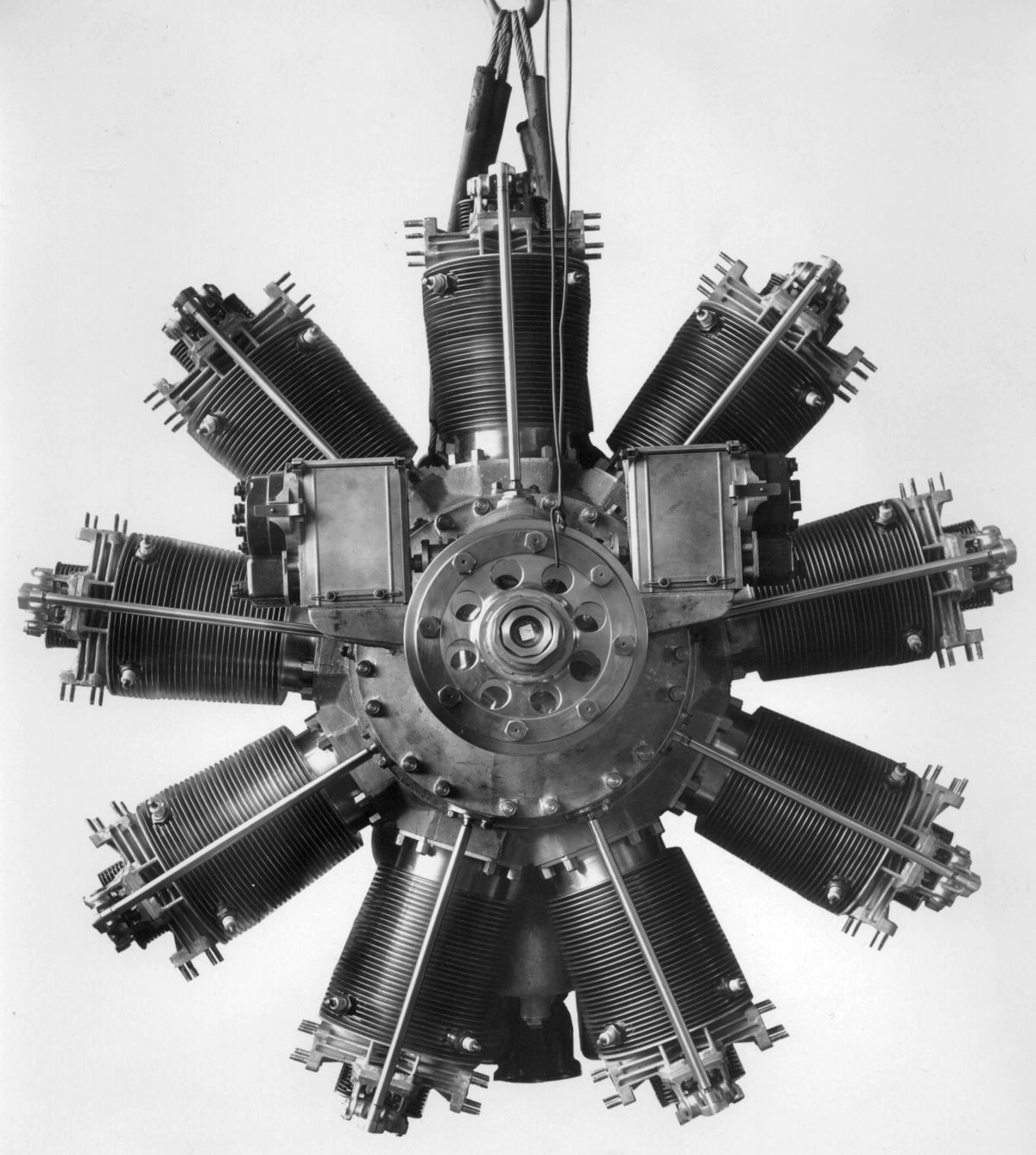
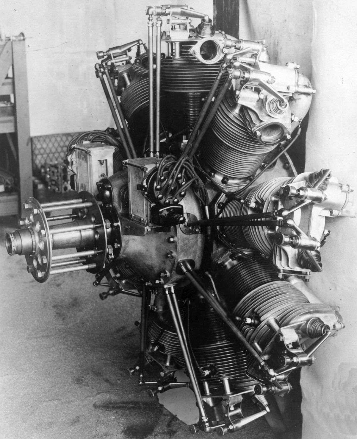
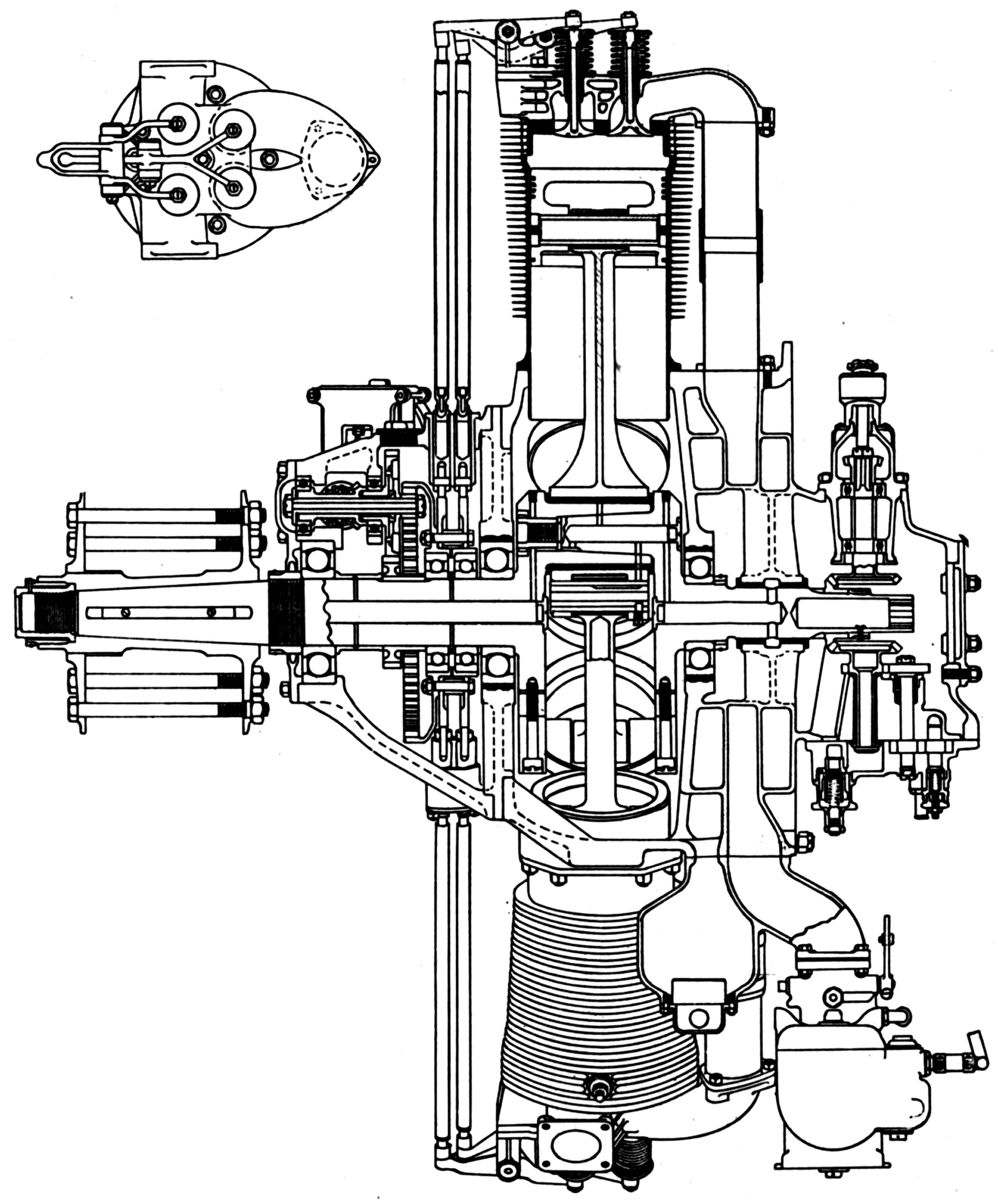
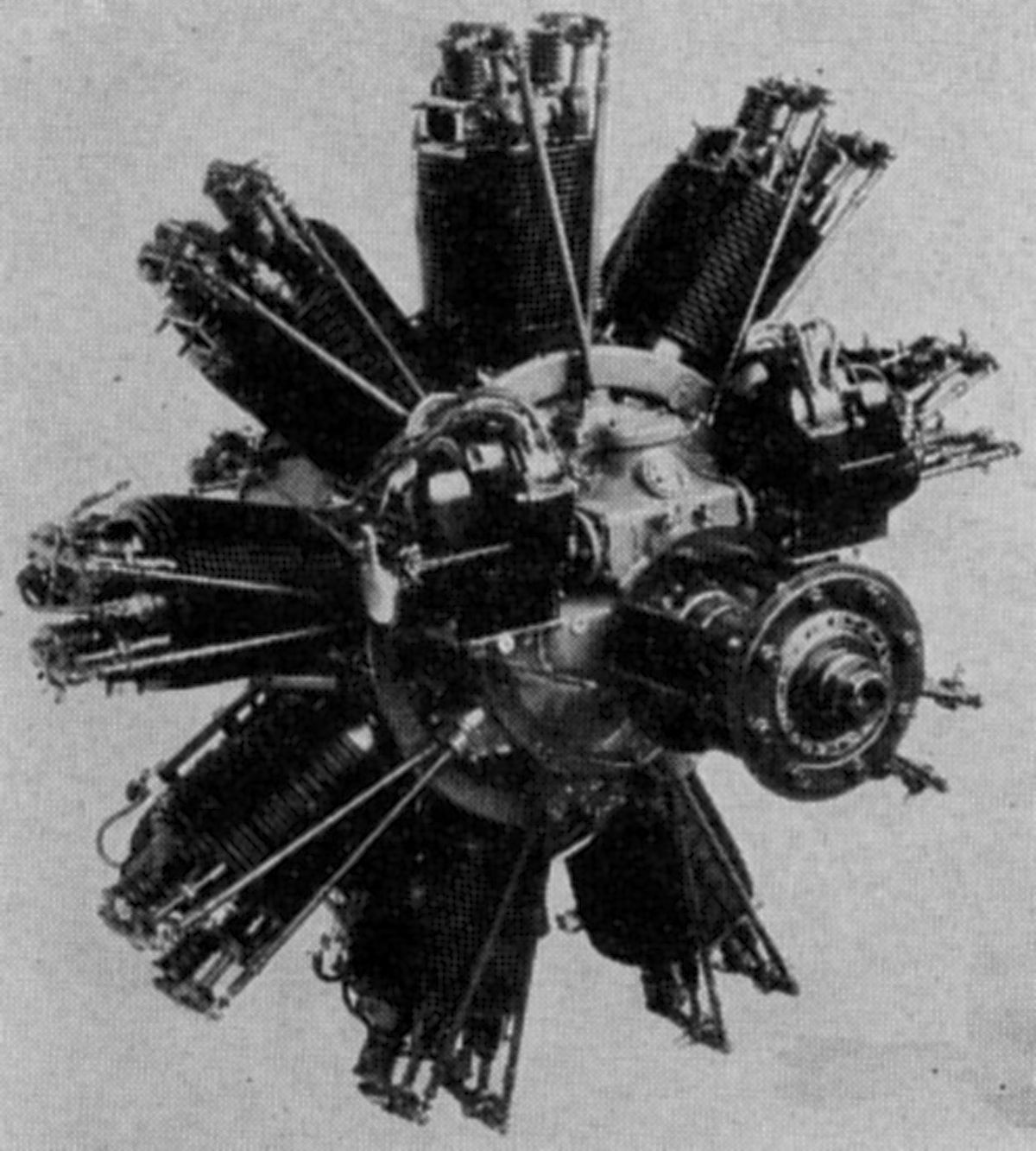
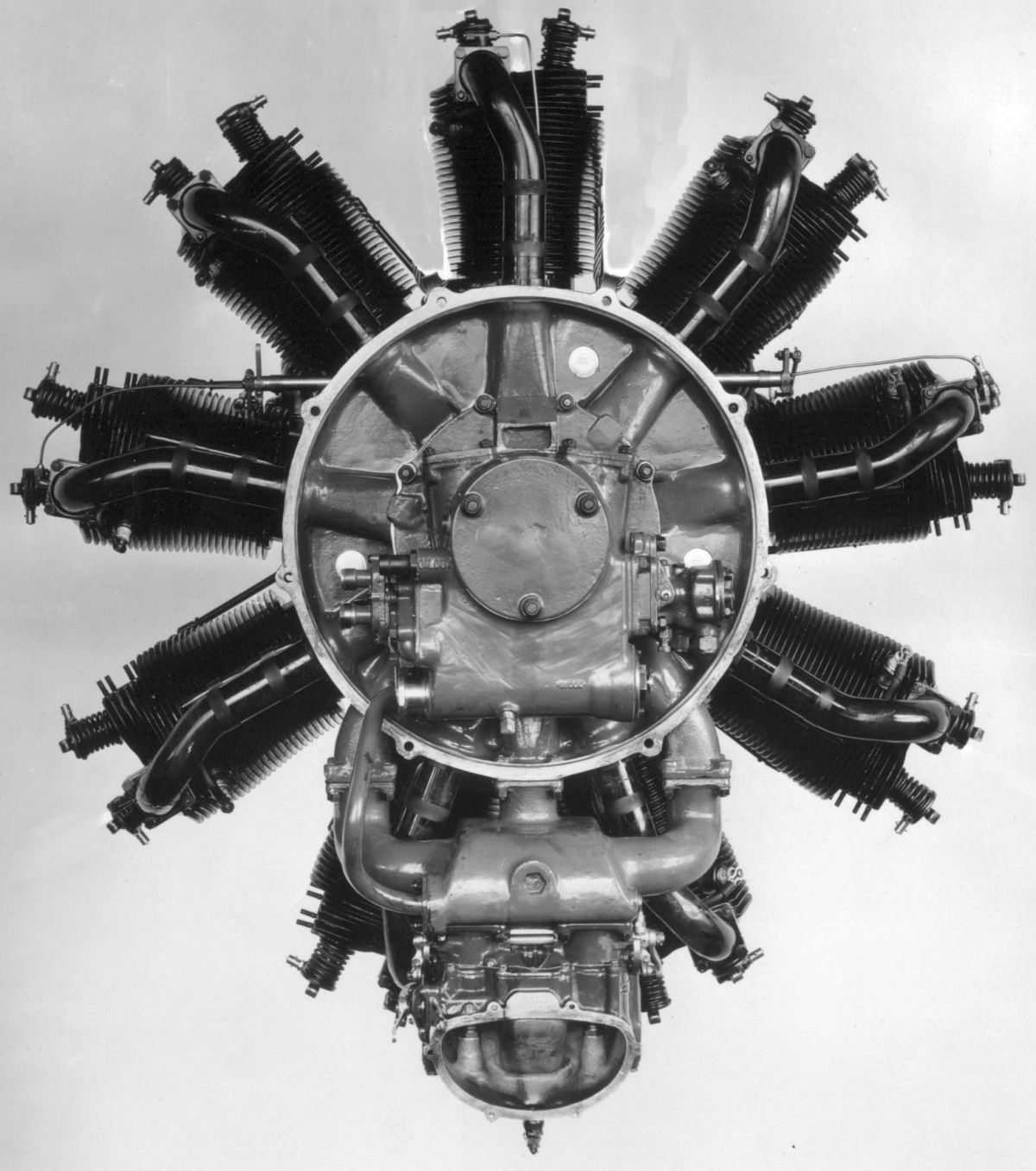
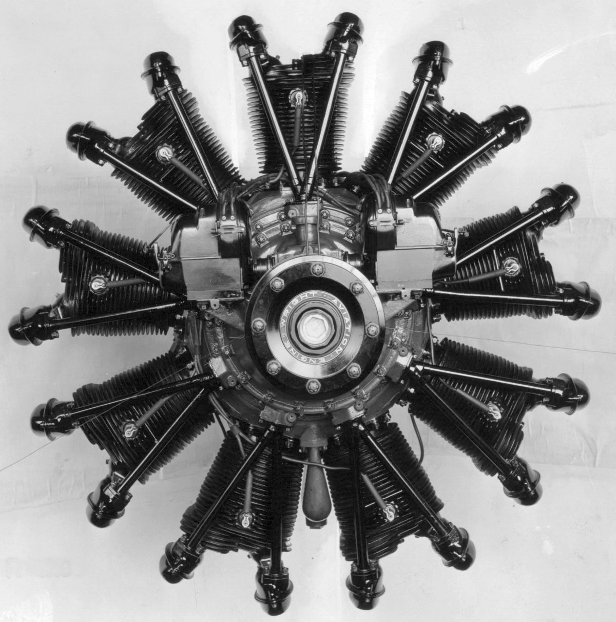
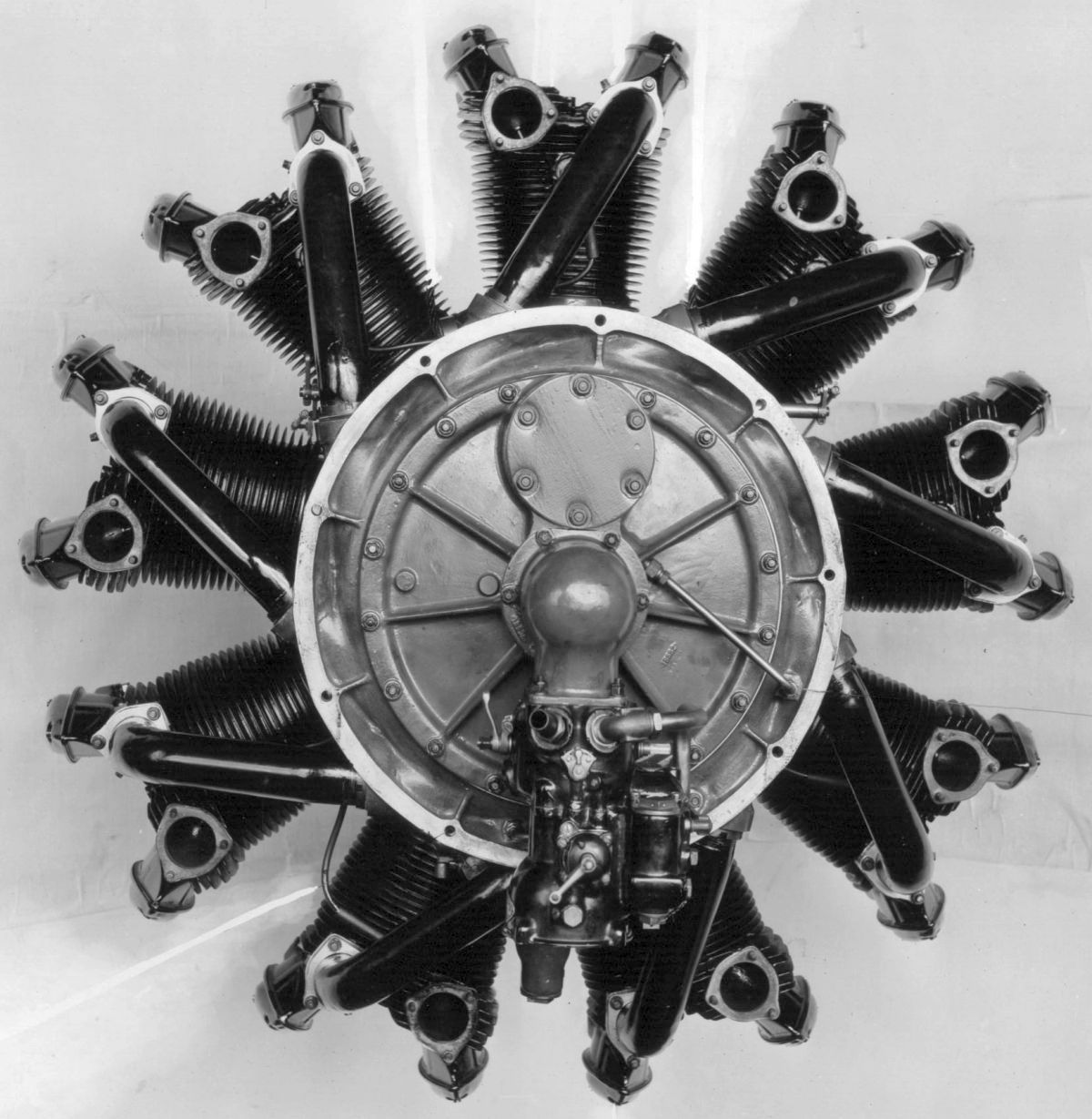
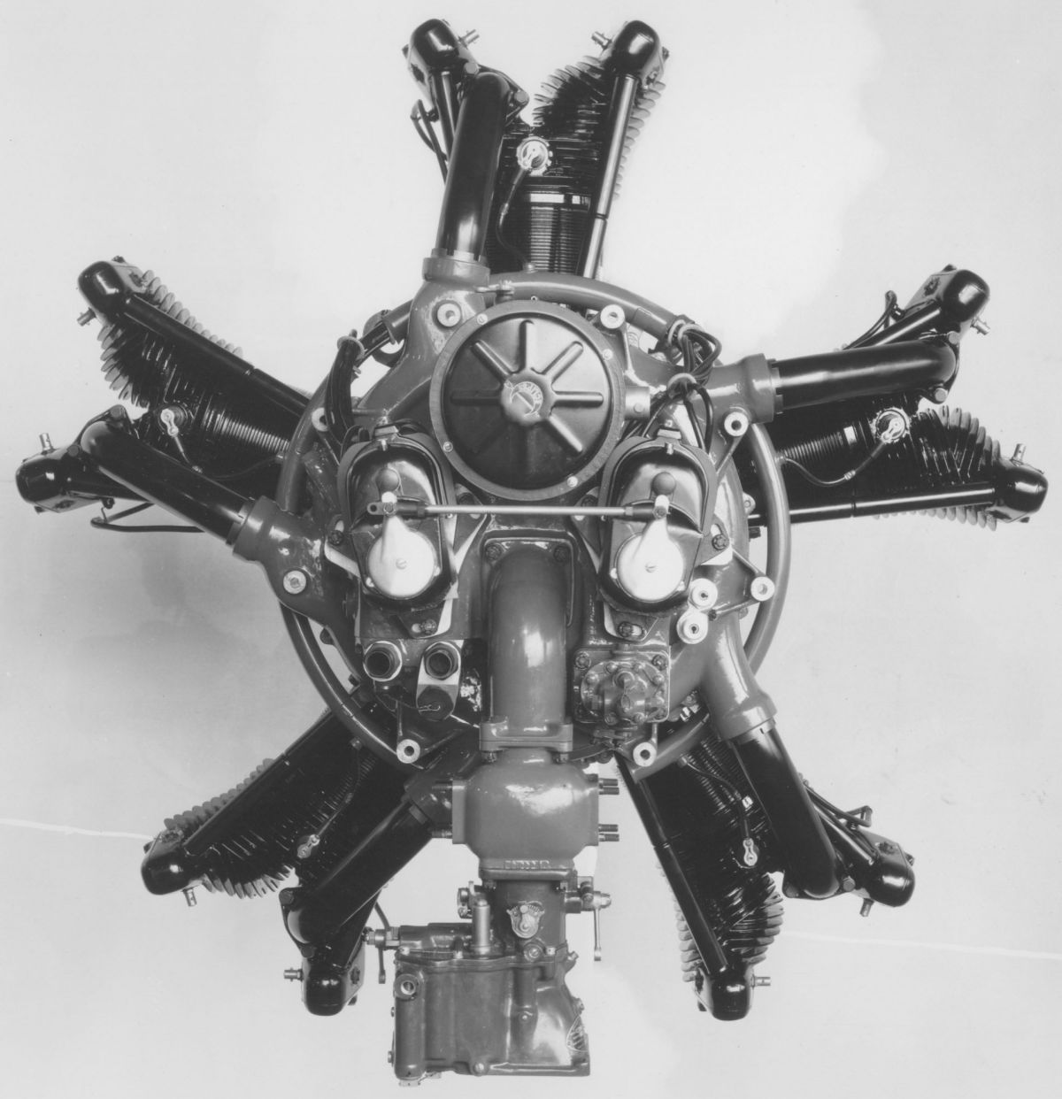
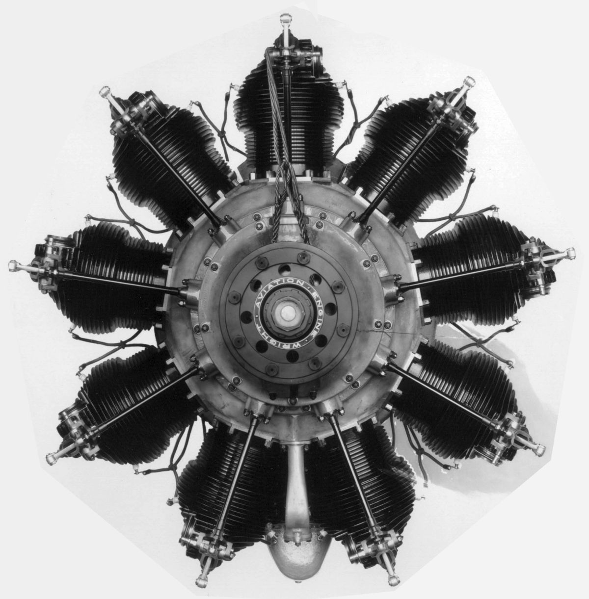
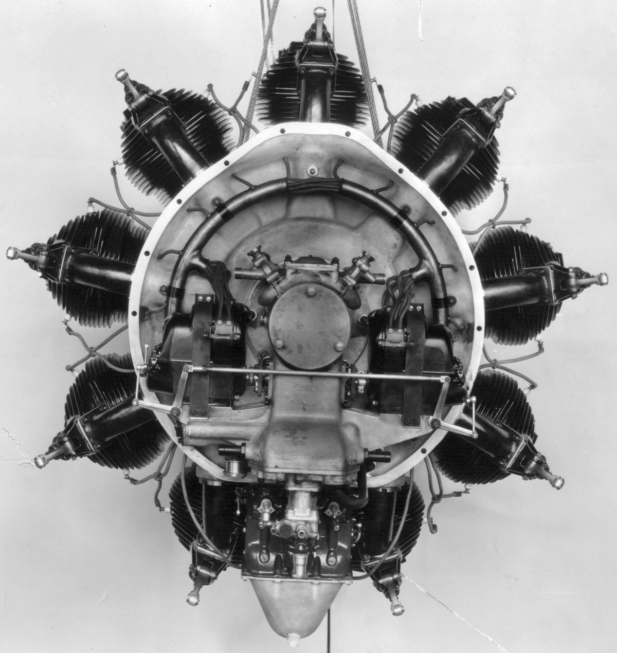
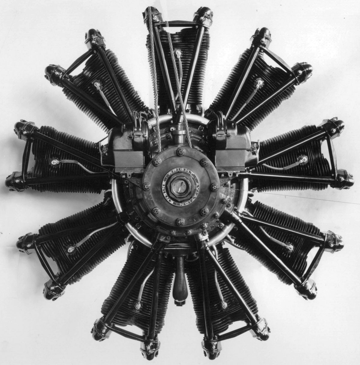
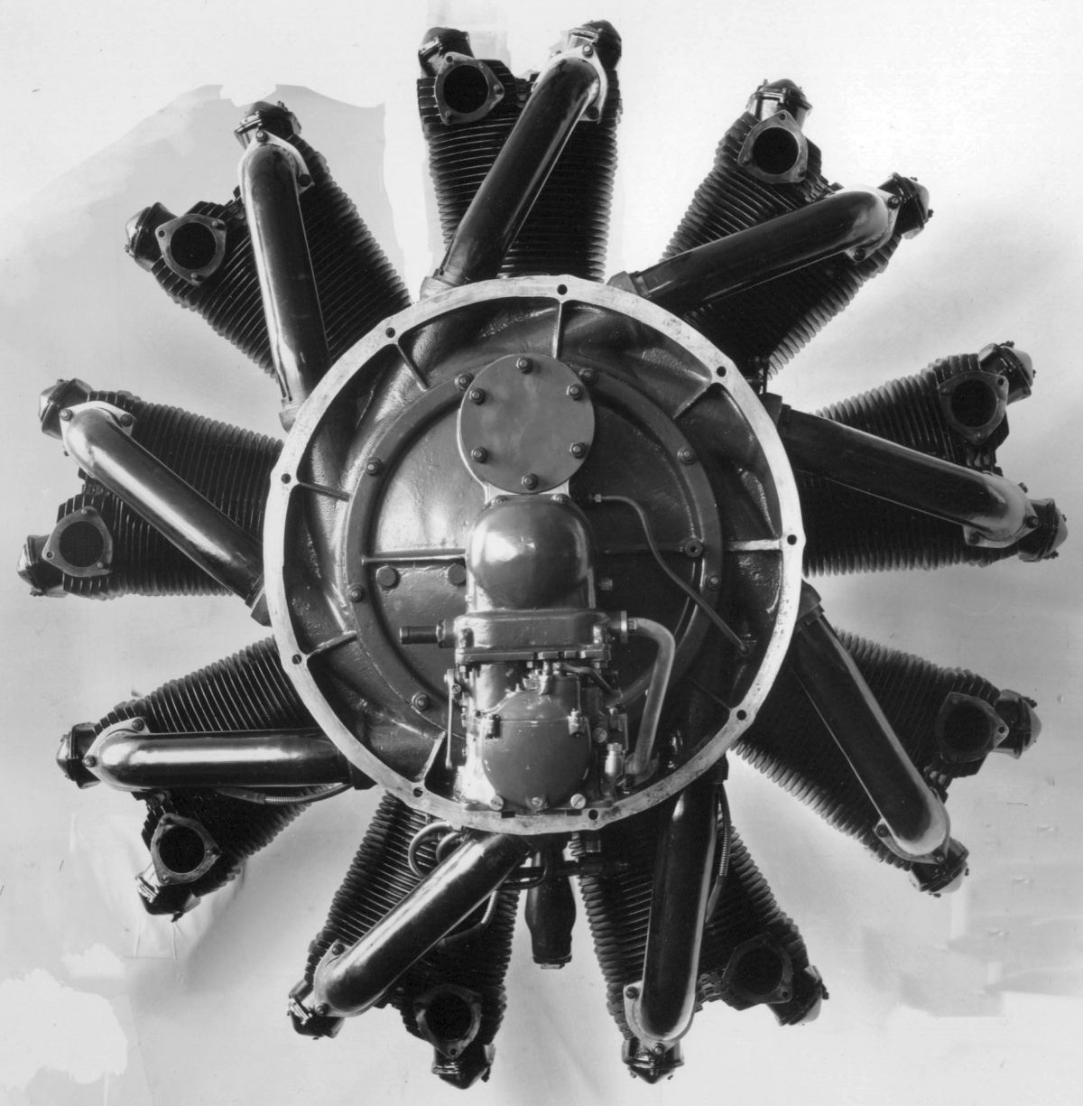
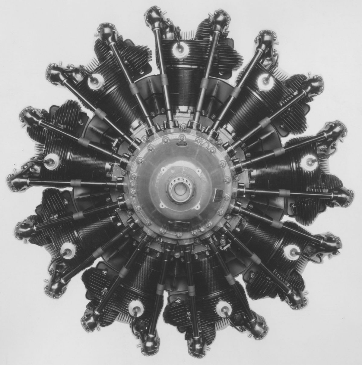
WAC began air-cooled engine development in 1920 when the Army Air Service awarded an experimental contract for a radial nine with a 5.625" (142.88 mm) bore, 6.500" (165.10 mm) stroke and 1453.75 in³ (23.823 l) displacement rated 350 hp at 1,800 rpm. This was the Wright R-1.
The cylinders were machined from steel forgings, with integral cooling fins and a closed-end head, to which an aluminum casting containing the valve ports and valve guides was bolted. This poultice-type construction followed designs originated by Cosmos and Bristol in England; it had the disadvantage of poor thermal conductivity from the valves to the air cooling medium. Four vertical valves seated upon the steel head and were operated via push rods and rocker arms from cam rings at the engine front. The cam rings were bolted to an internal gear whose hub was supported by two ball bearings on the crankshaft. The internal gear was driven through double idler gears from the crankshaft The idler shaft supporting these gears also carried a bevel gear to drive two magnetos mounted to brackets on the crankcase nose section.
The master connecting rod had an H-section shank and a one-piece big end fitted with flanged bushings pressed in from either end. The articulated link rods had tubular shanks. The aluminum alloy pistons had flat heads, and each were fitted with four rings above the piston-pin, and an oil-scraper ring on the piston skirt. The two-piece single-throw crankshaft sections were held together by a taper, key, and nut joint at the crank pin. the The crankshaft ran on three ball bearings; the rear bearing was supported in the main crankcase, the one just ahead of the crank was in a plate bolted between the crankcase and nose piece, and the third bearing was at the nose piece front so that it carried the propeller thrust loads.
The induction system constituted three independent three-cylinder inlet manifolds. The crankcase contained three cored annular gas passages, each fed by a Stromberg carburetor. Each passage provided mixture to three evenly spaced cylinders through steel pipes that were flanged at the cylinder ends and joined by hoses and clamps at the crankcase. Cored head passages divided the mixture into individual cored passages to each inlet valve. A large flange at the crankcase rear attached the engine to the airplane. An accessory structure bolted to the crankcase aft face provided support for fuel and oil pumps, gun synchronizer drive, and tachometer, as well as a flange for mounting a standard electric starter. Oil was fed into the hollow crankshaft under pressure by a gear pump through a collar in the form of a plain bearing located aft of the rear ball bearing. This plain bearing led oil into the crankshaft. Excess oil drained into a special sump that was cast integral with the carburetor elbows, and bolted to the crankcase underside. A suction pump drew excess oil from this sump through a passage into which an oil thermometer was inserted.
During 1921, the Air Service Engineering Division undertook developing a more suitable R-1 cylinder. Numerous cylinders were tested on the Universal Test Engine for a period of two years or more. A contract to build another engine with new cylinders was given to WAC when tests indicated these cylinders were acceptable. However, engine tests were not entirely satisfactory, and the Engineering Division took over the design and did additional cylinder and other engine parts development. The later composite R-1 cylinders employed a cast aluminum-alloy head with a hemispherical combustion space that was screwed and shrunk onto a steel barrel with integral circumferential cooling fins. These heads were fitted with aluminum-bronze spark plug bushing and valve seats. Two valves, inclined to the cylinder axis, were operated by push rods and rocker arms. The rocker arms had plain bearings and were supported upon a built-up steel bracket attached by studs and by bolts passing through bosses on the cylinder head. The inlet port faced aft and the exhaust port to one side.
During 1923, the U.S. Navy essentially forced WAC to absorbed the Lawrance Aero Engine Company, resulting in WAC obtaining the air-cooled radial engine designs that Charles L. Lawrance had been developing for years. Lawrance became president of WAC when Rentschler resigned and continued in that capacity until late 1930.
 |
| WAC J-3 (NARA) |
The J-3, a refinement of the Lawrance J-1 radial nine, appeared in 1924. Like its predecessor, the J-3 had a 4.500" (114.3 mm) bore, a 5.500" (139.7 mm) stroke and a 787.26 in³ (12.901 l) displacement. Its normal rating was 200 hp at 1,800 rpm. Principal improvements over the J-1 included strengthened crankshaft, connecting rods, and crankcase. The J-3 cylinders provided bronze spark plug bushings, a harder bronze for the valve seats, and thicker metal around the combustion chamber and valve seats. The auxiliary units layout was simplified, and a Stromberg NAU-5 three-barrel carburetor was substituted for the three single carburetors the J-1 had used. The lubrication system pumps, strainer and pressure relief arrangements were improved.
 |
 |
 |
 |
 |
| WAC J-4 (NARA) | WAC J-4B (NARA) | |||
The J-4 Whirlwind (as the series was now called) of 1924 retained many J-3 features, but incorporated further improvements based on J-3 service experience. Most notable was that the J-4 cylinder used a steel barrel that was screwed and shrunk into the aluminum-alloy head, with the cylinder hold-down flange integral with the barrel instead of a part of the external aluminum muff as in previous practice. The J-4A soon followed, incorporating a few minor changes including substituting Scintilla for Splitdorf magnetos, and adding a fuel pump drive. The J-4B had a different cylinder head with the top spark plug moved to the cylinder front, opposite the aft spark plug, and the inlet port moved from the cylinder center line to a position nearer the inlet valve. These two changes permitted undisturbed airflow across the cylinder head and much better cooling.
 |
 |
 |
| WAC Gale (NARA) | ||
WAC continued to manufacture the Lawrance L-4 engine for a time after the Lawrance Aero Engine Company was acquired. Known as the Wright Gale, this air-cooled radial three was rated 60 hp at 1,800 rpm and weighing 175 lb (79 kg). This design was essentially unchanged.
 |
 |
 |
| WAC Simoon (NARA) | ||
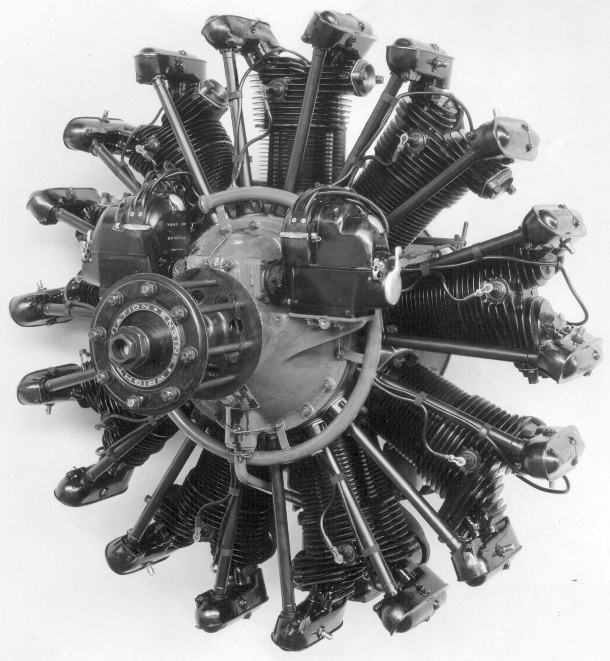
Wright Simoon development began in 1925 for use in single-seat shipboard Navy Department fighters. With more displacement than the Whirlwind, it promised to fill a need for radial air-cooled engines that could deliver well over 200 hp. The nine-cylinder Simoon, which also was referred to as the Wright R-1200, had a 5.500" (139.7 mm) bore and stroke, giving a 1176.04 in³ (19.272 l) displacement. Originally the Simoon was rated 300 hp, but it delivered 340 hp at 1,800 rpm and 350 hp at 1,900 rpm during tests. The dry weight 640 lb (290 kg), and the compression ratio 5.0:1.
The Simoon's general arrangement was similar to the Wright Whirlwind, with the valve gearing and magnetos at the engine front and the auxiliary units at the rear. The cast aluminum alloy cylinder heads were screwed and shrunk onto forged steel barrels with integrally-machined cooling fins. The valves were incline to the cylinder axes and were operated via fully enclosed push rods and rocker arms. The tubes that enclosed the push rods also supported the forward rocker box ends, the aluminum rocker box castings supporting the rocker arms and, with the sheet aluminum covers, also forming an enclosure for them. Grease was forced into the roller bearings supporting the rocker arms through Alemite fittings. The articulated connecting rod system employed a master rod with a split big end, and an H-section shank. The aluminum-alloy pistons had ribs underneath the heads. Two Scintilla magnetos mounted on crankcase nose section brackets provided dual ignition. The carburetor was mounted at the crankcase rear section and fed a compartment containing a low-altitude centrifugal supercharger that was driven through gears from the crankshaft. Provision were made on the rear crankcase for mounting a starter, fuel pump, and gun synchronizers. The Wright Simoon was to become the bait that the U.S. Navy cast before the fledgling Pratt & Whitney Aircraft Company to inspire P&W to build the Wasp, which first ran on 28 Dec 1925.
 |
 |
| WAC J-5 (NARA) | |
Another J-series Whirlwind, the J-5, first ran in 1925. This engine became especially famous because of its general use during what might be termed the publicity and stunt epoch of aviation history. The J-5 powered several endurance flights, including those involving aerial refueling, and practically all successful transoceanic flights starting from the U. S., along with historic flights in the Polar regions.
The J-5 retained 4.500" (114.30 mm) bore, 5.500" (137.70 mm) stroke, and 787.26 in³ (12.901 l) displacement and 5.2:1 compression ratio of older engines. Guaranteed sea level output at was 200 hp at 1,800 rpm. Fuel and oil consumptions were 0.60 and 0.025 lb/hp/hr. Dry weight was 508 lb (230 kg), diameter was 45" (1,143 mm) and the length, not including the starter, was 34" (864 mm). The Department of Commerce issued the J-5 Approved Type Certificate (ATC) No. 13 on 26 Jan 1929, rating it 200 hp at 2,000 rpm. The most important J-5 design change was the J-5 cylinder, which had fins machined on the steel barrel of which the upper 1.75" (44.45 mm) was screwed and shrunk into an aluminum-alloy head. Previously these fins had been cast integrally with the aluminum head and outer barrel casting of the J-4B design. The valves of the J-5 cylinder were placed at a greater angle to the cylinder axis, inclined at 35° angles as compared to J-4B's 8.75° angle. The tulip-type valves were machined from tungsten steel. The hollow exhaust valve stems were partly filled with a metal salt (later elemental sodium) to assist in cooling. Each valve was held to its seat by three concentric helical round steel wire springs. The valves seated upon aluminum-bronze valve seats that were shrunk into the hemispherical combustion chamber, and diametrically-pposite bronze spark plug bushings in the combustion chamber sides were at a 10° angle to the crankshaft axis. The J-5 rocker arms and push rods were fully enclosed. The cast aluminum rocker arm boxes formed rocker arm shaft supports, and were closed by pressed-steel covers. Screws at the rocker arm outer ends provided valve clearance adjustment.
Five aluminum-alloy castings comprised the crankcase. The front section contained the thrust bearing housing, magneto brackets, and magneto and cam driving gears. The intermediate section contained the cam and valve tappet mechanism, and a housing for the front crankshaft hearing. The main section had cylinder attachment pads, a flange for mounting to the airplane, a housing for the rear crankshaft bearing, and inlet gas passages. The rear section carried oil pump, fuel pump, gun synchronizer, and tachometer drives. It also provided starter and oil strainer housing mountings. The aft section served as an oil sump, and contained inlet passages from the three-barrel Stromberg carburetor bolted underneath. The induction system was in reality three independent three-cylinder manifolds.
The single-throw crankshaft was machined all over from a solid chrome-nickel steel forging, and the counterweights were bolted to crank cheek extensions. The crankshaft ran on three ball bearings, the forward one carrying propeller thrust loads. A rear plain bearing admitted oil. The articulated connecting rods used an H-section master rod whose split big end was fitted with white-metal-lined steel-backed bearings. The link rods had tubular shanks. The cast aluminum-alloy pistons were heavily ribbed under the heads. Three compression rings were fitted above the piston pin and an oil-scraper ring was located below. The full-floating piston pin ends were fitted with aluminum plugs.
WAC built 3,339 J-1 through J-5 series Whirlwind engines between 1923 and 1930.
The Whirlwind J-6 Series, introduced by WAC in 1928, to extend the power range and reduce manufacturing costs, included three radials with 5, 7 and 9 cylinders; most parts were interchangeable. In a departure from previous designs the cam mechanism and all other accessories, were behind the power section. J-6 cylinders used steel barrels with aluminum-alloy heads screwed and shrunk on. The inlet port faced aft and the exhaust port faced forward, but the radial position of the two were reversed. In the use of a front exhaust collector ring there was less air flow interference over the cylinder when the exhaust port was located at the cylinder left side as viewed from the front. J series valves were inclined to the cylinder axis and aluminum-bronze seats were shrunk into the hemispherical combustion chamber. The tulip-type valves had a solid inlet stems and hollow exhaust stems; each was seated by three helical round-wire springs. The hollow steel tube push rods were fitted with hardened ball ends, and the rocker arms were steel forgings running on ball bearings. The valve operating mechanism was completely enclosed.
The crankshaft was made from two steel forgings, resulting in a one-piece master rod fitted with a steel bearing shell lined with antifriction metal. The aluminum-alloy pistons were cross ribbed under the slightly concave head, and the full-floating piston pins were held endwise by expanding spring wire locks. The dry-sump pressure-fed lubricating system used gear pumps, and two Scintilla magnetos furnished dual ignition. The fuel mixture was supplied by a Stromberg carburetor mounted on the crankcase rear section. After leaving the carburetor, the mixture entered a diffuser where the rotary impeller distributed it to all cylinders through the pipes connecting the diffuser with the cylinder inlet ports. A hot spot was provided above the carburetor to assist in fuel vaporization.
All Wright J-6 engines had a 5.000" (127 mm) bore, a 5.500" (139.7 mm), and the first models had a 5.1:1 compression ratio. Fuel and oil consumptions were 0.55 and 0.035 lb/hp/hr. The same mounting ring dimensions was used for all three models and the distance from the mounting flange to the propeller hub was 28.906" (734 mm). Diameter was 45" (1,143 mm). Inlet valves opened 10° early and closed 60° late; exhaust valves opened 75° early and closed 39° late.
 |
 |
 |
| WAC R-540 (NARA) | ||
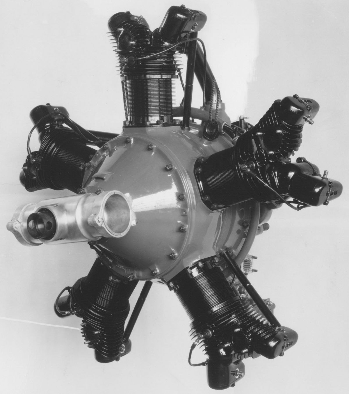
The Whirlwind R-540 was a J-6-series radial five with a 539.96 in³ (8.848 l) displacement whose rated output was 165 hp at 2,000 rpm, according to ATC No. 23 dated 27 Mar 1929. Dry weight was 370 lb (168 kg). With standard equipment, including air cleaner and heater, exhaust pipes and collector ring, and nose cowling, the weight was raised to 402 lb (182 kg) The length (without starter) was 40.625" (1,032 mm). On 18 Aug 1931, ATC No. 23 was revised to include the geared the GR-540 series. This revision comprised the direct-drive R-540A, R-540B, R-540D, R-540E, and their geared companions the GR-540A, GR-540B, GR-540D and GR-540E, with ratios of 1.58:1 or 2.0:1. On 10 Oct 1932, the certificate was revised to show a rated output of 175 hp at 2,000 rpm.
The R-540E weighed 420 lb (191 kg), used a 5.1:1 compression ratio and the 1:7.05 blower ratio. The GR-540E engine, with 1.58:1 reduction gears, weighed 470 lb (213 kg), or 480 lb (218 kg) with the 2.0:1 propeller reduction gear ratio was used.
WAC built 546 R-540 engines between 1929 and 1937.
 |
 |
 |
| WAC R-760 (NARA) |
The Whirlwind R-760 was a J-6-series radial seven with a 755.95 in³ (12.388 l) displacement. Originally awarded ATC No. 26 on 9 Jul 1929, the revised 26 Mar 1930 certificate carried a 240 hp at 2,000 rpm rating. The 18 Aug1931 revision included the geared GR-760, along with the R-760A, R-760B, R-760D and R-760E, and the geared types GR-760D, GR-760A and GR-760E employing either a 1.58:1 or 2.0:1 propeller reduction ratio. Dry weight was 425 lb (093 kg) and 460 lb (209 kg) with standard equipment. Length (without starter) was 40.72" (1,034 mm).
The revised 10 Oct 1932 certificate increased the rated output to 250 hp at 2,000 rpm. The 27 Nov 1933 revision listed a 495 lb (225 kg) dry weight, a 5.1:1 compression ratio and 1:7.05 blower gear ratio. Later R-760E engines weighed 520 lb (236 kg), and the GR-760E geared engine with a 1.58:1 reduction ratio weighed 570 lb (259 kg) and with a 2.0:1 ratio weighed 580 lb (263 kg). The 11 May 1936 ATC No. 26 specified 530 lb (240 kg) weight, including carburetor air heater and cleaner. The 10 Feb 1937 revision covering the R-760E also included the R-760, R-760A, R-760B and R-760D engines included no important changes, with the rated output remaining 250 hp at 2,000 rpm. Stromberg NA-R7A or NA-R7 carburetors with 2.0625" (52.39 mm) venturis were specified, along with dual ignition supplied by Scintilla MN-7-DF magnetos.
The R-760E-1, a moderately supercharged high-compression J-6 Series radial seven received Type Certificate No. 94 on 9 Jan 1933 with 285 hp at 2,100 rpm rating. Its compression ratio was 6.0:1, its blower gear ratio was 1:7.05, and its bare weight 505 lb (229 kg). An 11 May 1936 specification listed a 545 lb (247 kg) weight, which included carburetor air heater and cleaner. A 10 Nov 1936 revision specified a 6.3:1 compression ratio change. A 10 Feb 1937 revision specified a 6.1:1 compression ratio and 73 octane fuel. The rated output remained 285 hp at 2,100 rpm. A Stromberg NA-R7 or NA-R7.1 carburetor with 2.0625" (52.39 mm) venturi supplied the mixture, and Scintilla MN-7-DF magnetos provided dual ignition. A 27 Oct 1937 revision gave a 300 hp at 2,250 rpm one-minute takeoff rating. Dry weight, including carburetor air heater and cleaner, was 565 lb (256 kg). A revision dated 11 Dec 1937 added the use of Scintilla SF-9R magnetos, and another dated 21 Dec 1937 added Scintilla VAG-9DF magnetos. The specification dated 17 Jan 1938 incorporated all above revisions.
The R-760-ET was covered by Type Certificate No. 126, issued on 5 Jul 1934. With a 6.0:1 compression ratio and operating on 73 octane fuel, it was rated 235 hp at 2,000 rpm and weighed 500 lb (227 kg), 515 lb (234 kg) with carburetor air heater and cleaner. The specification dated 10 Feb 1937 increased the compression ratio to 6.1:1 with 73 octane fuel but did not change the rated outputs. Either a Stromberg NA-R7 or a NA-R7 A carburetor with 2.0" (50.8 mm) venturi supplied the mixture. The specification revision dated 21 Dec 1937 approved the use of Scintilla MN-7-DF, SF-7R or VAG-71DF magnetos.
The direct-drive R-760-E2, which received Type Certificate No. 155 on 10 Dec 1935, had a 6.3:1 compression ratio, 1:9.17 supercharger impeller ratio, and required 80 octane fuel. It was rated 320 hp at 2,200 rpm at sea-level. It weighed 515 lb (234 kg ) dry, and 560 lb (254 kg) with carburetor air heater and cleaner. A revised 21 Dec 1937 specification approved Scintilla MN-7DF, SF-7R or VAG-7DF magnetos. The dry weight was raised to 570 lb (259 kg) when cylinder head and barrel baffles were included. This is the first mention of WAC providing cylinder baffles. Prior to this, airframers were left pretty much on their own to baffle installed engines, if at all. As engine power levels increased, the need to maximize heat transfer the cooling air became more critical. Hence, WAC started to supply baffles for the higher-powered Whirlwind and Cyclone engines, which by all accounts worked very well. However, WAC appears to have lost it way when baffling the early R-3350s, a mistake that resulted in numerous engine failures and fires.
The 1935 J-6-series R-760-ET, R-760-E. R-760-E1 and R-760-E2 previously described included minor changes in compression ratio and supercharging to give a 235 hp to 320 hp power range and conform with Department of Commerce ruling regarding engine interchange for increased altitude performance. Other construction changes were numerous. The crankshaft was lengthened, and the splines changed from SAE No. 30 to No. 20 to save about 49 lb of weight by permitting the use of a lighter and more efficient. controllable-pitch propeller hub. These engines were also provided with the dynamic vibration absorber first introduced on the Wright Series F and F-50 Cyclones. Inter-cylinder baffles and cylinder head air deflectors were also provided to give full pressure baffling on all supercharged models. Each baffle was individually detachable, which permitted the removal of any one cylinder, or group of cylinders, without removing all baffles. These baffles forced the cooling air to follow the cylinder head and barrel contours to insure efficient cooling in tightly cowled installations.
These engines could be fitted with several controllable or fixed-pitch propeller models. Propeller control mechanisms for hydraulically-controllable types were enclosed in the crankcase nose section, a two-way valve regulating the engine oil pressure to change to the pitch. Supplementing the centrifugal band clutch that protected the supercharger drive gear train from torsional vibration was a spring coupling that was incorporated into the main accessory drive gear that bolts to the crankshaft. The two-piece accessory drive gear shafts were joined via splined couplings. The cylinders and crankcase were materially strengthened, and changes to insure oil tightness at several points were incorporated. The forged aluminum-alloy pistons were ribbed under the heads ribbed for strength and additional cooling surface. The flat-head pistons had a 6.0:1 compression ratio and the concave-head pistons had a 5.1:1 ratio.
The cylinders had side exhaust ports with detachable finned elbows that permitted using either front or rear exhaust collector rings. Rocker boxes were integrally cast with the cylinder heads and closed by clamped-on covers that provided rigid support for anti-drag cowling. The tulip-shaped hollow-stem exhaust valves were filled with sodium.
The built-in supercharger was driven at approximately 7 to 10 times engine speed, depending upon the requirements. The supercharger section was a diaphragm carrying the impeller and its drive. The diffuser and distribution chamber was formed between this section and the rear crankcase section, which supported the accessories and accessory drives, as well as attaching to the engine mounting ring.
WAC built 1,414 R-760 engines between 1929 and 1945; NAF built 1,127 under license between 1937 and 1942. Conversion of military R-760s to civilian service was approved under Type Certificate 5E-6.
 |
 |
|
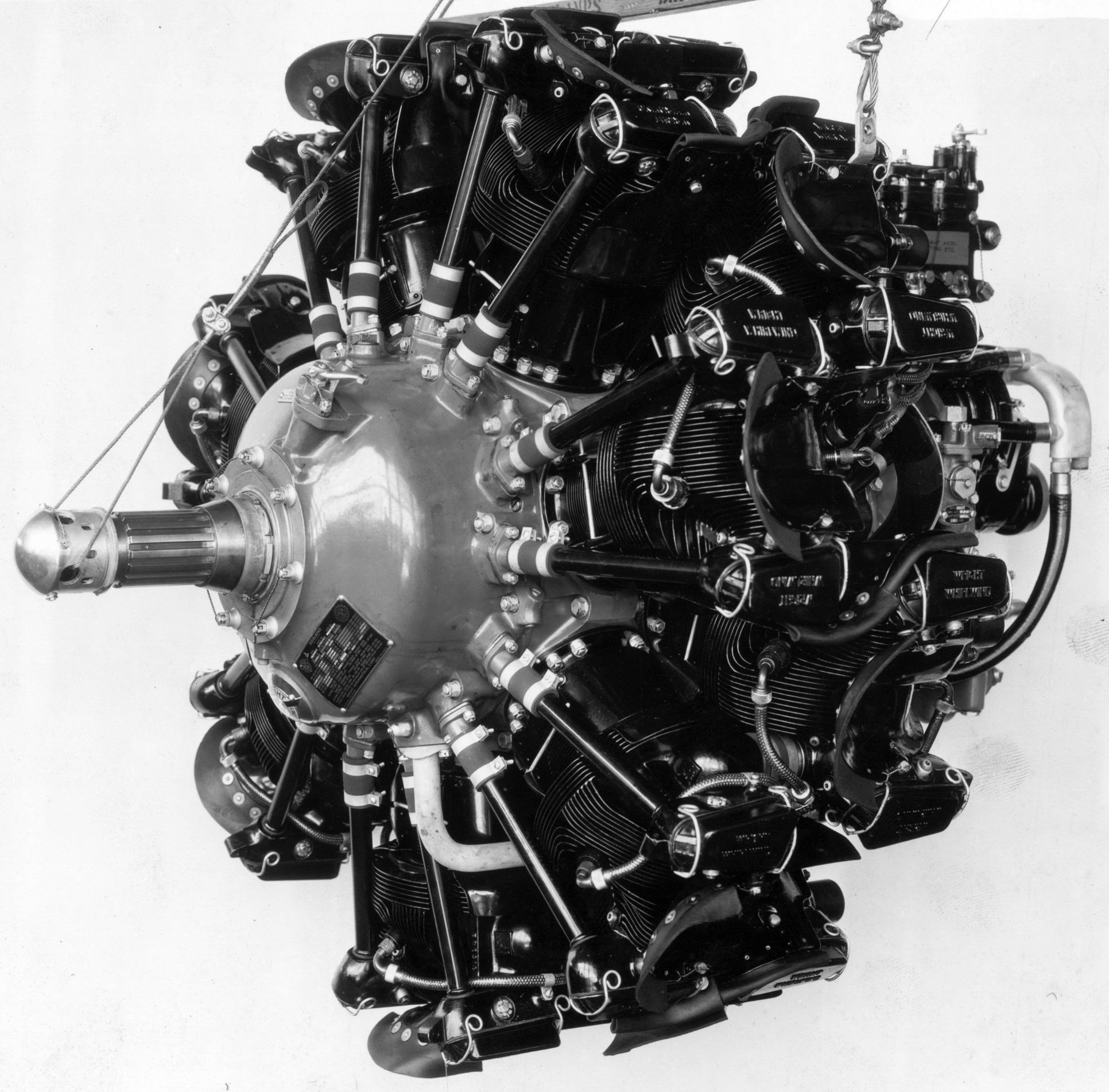
| WAC R-975 (NARA) | ||
The Whirlwind R-975, a J-6-series radial nine that displaced 971.93 in³ (15.927 l), was granted ATC No. 21 on 15 Feb 1929; this type certificate included the geared GR-975 and carried an approved 300 hp at 2,000 rpm rating at a 520 lb (236 kg) dry weight. This increased to 550 lb (249 kg) when standard equipment was included. Length (without starter) was 41.4375" (1,053 mm). Extra accessories included an Eclipse hand inertia starter weighing 21 lb (9.5 kg), a 15-volt 15-amp Eclipse generator weighing 16 lb (7.3 kg), a generator control box weighing 2.5 lb (1.1 kg), a modified Wright C-3 fuel pump weighing 2 lb (0.9 lb), and a Standard Steel propeller hub of weighing 23 lb (10.4 kg).
As improvements were made in the course of R-975 development, ATC No. 21 was revised on 18 Aug 1931 to include the direct-drive R-975A, R-975B, R-975D, R-975E, , and their geared companions, the GR-975A, GR-975B, GR-975D and GR-975E, with either a 1.58:1 or 2.0:1 propeller reduction gear ratio. On 10 Oct 1932, the rated output of these engines was raised to 325 hp at 2,000 rpm, and then to 330 hp at 2,000 rpm on 8 Nov 1932. This specified 73 minimum octane fuel, a 1:7.8 ratio supercharger impeller drive, and a 5.1:1 compression ratio. Stromberg NA-R9 or NA-R9A carburetors with 2.4375" (61.91 mm) venturi were used, and Scintilla VAG-9DF magnetos furnished dual ignition.
The R-975C, with a 1:10.15 supercharger impeller ratio, received a 400 hp at 2,300 rpm rating by ATC No. 64, issued on 29 Oct 1930. On 18 Aug 1931 the certificate was revised to include the similarly-rated GR-975C, a geared companion available with a 1.58:1 or 2.0:1 propeller reduction gear ratio.
The R-975E-1 was an improved version incorporating most of the changes made available on all Whirlwind and Cyclone engines. These consisted principally of E-type cylinder heads with spark-plug coolers, and integrally-cast rocker boxes. The tangential manifold and centrifugal supercharger band clutch for were incorporated. The rated output became 365 hp at 2,100 rpm according to Type Certificate No. 87, issued on 29 July 1932, and reissued on 27 Sep 1932 to include the GR-975E-1, a geared companion with either 1.58:1 or 2.0:1 ratio. Dry weight of the geared engine (less propeller hub and starter) was approximately 635 lb (288 kg) with the 1.58:1 ratio, and 645 lb (293 kg) with the 2.0:1 ratio. Length was 47" (1,194 mm). Fuel and oil consumptions were 0.55 and 0.035 lb/hp/hr.
Type Certificate No. 87, dated 10 Feb 1937, covered only the direct-drive R-975E-1. The rated output remained 365 hp at 2,100 rpm for maximum continuous and one-minute takeoff. This engine employed a 6.1:1 compression ratio, had a 1:7.8 supercharger impeller gear ratio, and required 73 minimum octane fuel. Stromberg NA-R9 or NA-R9A carburetors with 2.4375" (61.91 mm) venturi supplied the mixture, and Scintilla VAG-9D magnetos provided dual ignition. Dry weight was 645 lb (293 kg), 660 lb (299 kg) including carburetor air heater and cleaner, and cylinder baffles. On 21 Dec 1937, Scintilla VAG-9DF or SF-9R magnetos were approved.
The R-975E-2, a 1932 further-improved Model R-975C, commonly called the Whirlwind 420, was issued ATC No. 78 on 4 Feb 1932 and reissued on 30 Jul 1932 to include the GR-975E-2 with either 1.58:1 or 2:1 propeller reduction gearing. Output was 400 hp at 2,150 rpm, and the normal rated output was 420 hp at 2,150 rpm. Weight was 590 lb (268 kg), and length was 41.84" (1,063 mm). The supercharger impeller ratio remained 1:10.15 but the compression ratio was raised to 6.0:1 as in the R-975E-1 model. Cylinder and exhaust valve cooling improvements were incorporated along with a beefed-up supercharger drive that included a centrifugal wrapping-band clutch in the intermediate drive gear. The clutch action provided a one-way supercharger impeller drive that permitted momentary slip when the throttle was opened suddenly. It also disconnected when the engine was stopped or idling , eliminating acceleration stress during starting.
A 21 Dec 1937 certificate revision called for a 6.3:1 compression ratio and 80 minimum octane fuel. R-975E-2 dry weight was 675 lb (306 kg), including carburetor air heater and cleaner, and cylinder baffles. Scintilla VAG-9D, VAG-9DF or SF-9R magnetos provided dual ignition.
The R-975E-3 was issued Type Certificate No. 125 on 3 May 1934. It was rated 440 hp at 2,200 rpm using 87 minimum octane fuel. Dry weight was reported to be 600 lb (272 kg).
The 1935 nine-cylinder Whirlwind series included refinements common to the 1935 seven-cylinder models. The 1935 nine-cylinder Whirlwinds were identical except for the amount of supercharging. The slightly supercharged R-975-E was rated 330 hp as before. The R-975-E1 used high-compression 6.0:1 pistons and delivered 365 hp at sea level.
The R-975E-3 used high-compression 6.3:1 pistons and was fully supercharged with a 1:10.15 impeller gear ratio. Rated sea-level takeoff output was 420 hp, with 450 hp at 2,250 rpm being available for one-minute. Basic dry weight was 615 lb (280 kg), 660 lb (299 kg) with carburetor air heater and cleaner, and 675 lb (306 kg) with cylinder baffles. A revised specification dated 21 Dec 1937 approved either Scintilla VAG-9DG or SF-9R magnetos.
The R-975-F received Type Certificate No. 211 on 25 Apr 1939. This was a refined version with a 6.3:1 compression ratio and Maximum Except Take Off (METO) rating of 425 hp at 2,300 rpm, 5,000 (1,524 m) feet pressure altitude and 33 inHgA manifold pressure. Sea level manifold pressure was limited to 35 inHgA. The one-minute takeoff rating was 475 hp at 2,400 rpm with a 37 inHgA manifold pressure. Fuel of 87 octane minimum was specified. Dry weight was 733 lb (333 kg), which included carburetor air-heater and cleaner and cylinder baffles. The propeller shaft was an SAE No. 30. Scintilla VAG-9DFR or SF-9R magnetos provided dual ignition. The supercharger impeller ran at 10.15 times crankshaft speed, and the mixture was supplied by Stromberg NA-R9A or NA-9RC carburetors with 2.625" (66.68 mm) venturi. The Whirlwind 450 DeLuxe was the name given to the R-975-E3 when it was equipped with shielded ignition.
WAC designed an R-975-C1 variant that powered the M4 Sherman tank; most of these were built under license by Continental Motors. A total of 68,887 R-975 engines were built by WAC and its licensees between 1929 and 1945. Conversion of military R-985s to civilian service was approved under Type Certificate 5E-7.
 |
 |
 |
 |
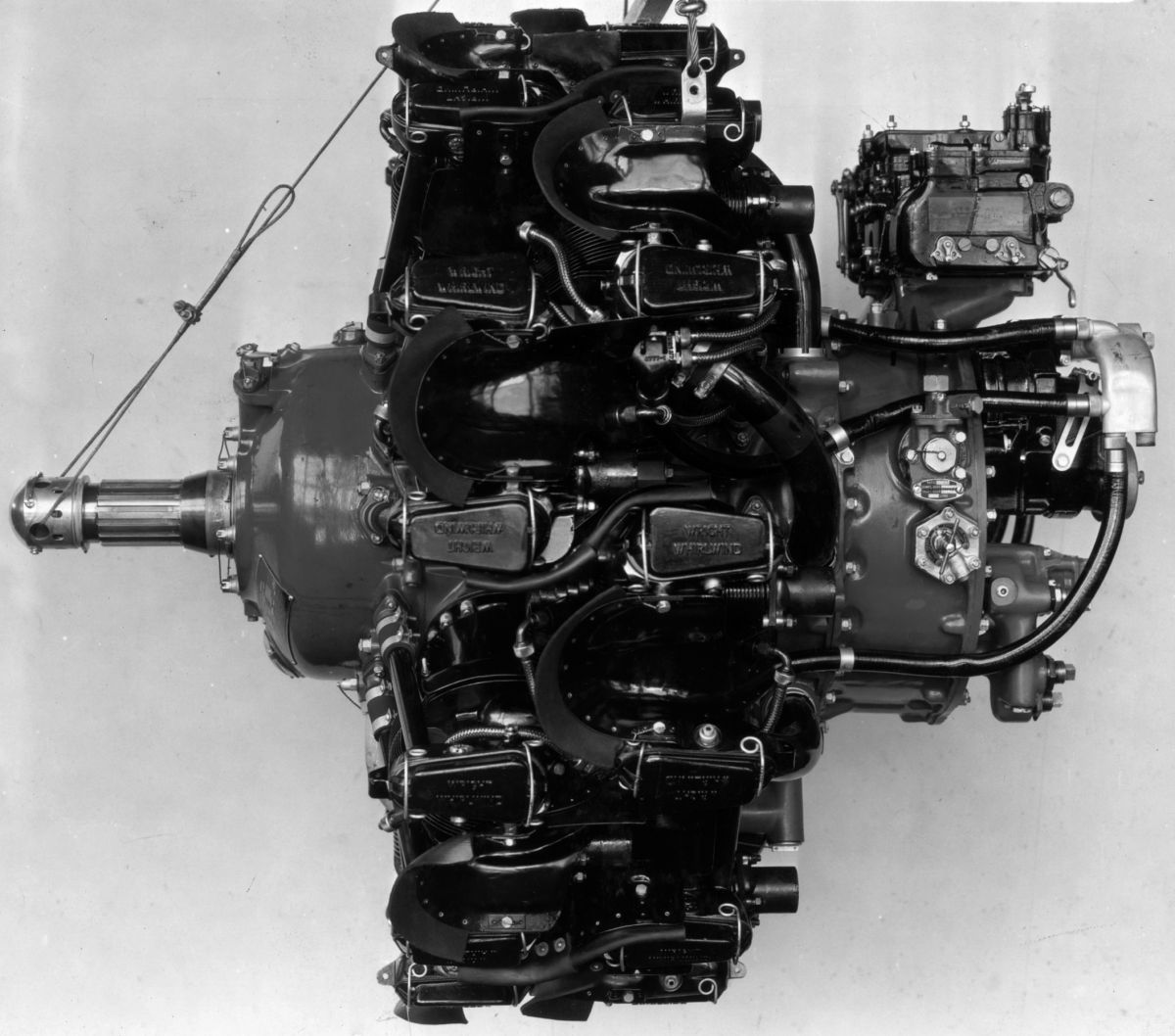
| WAC P-1 (NARA) | |||
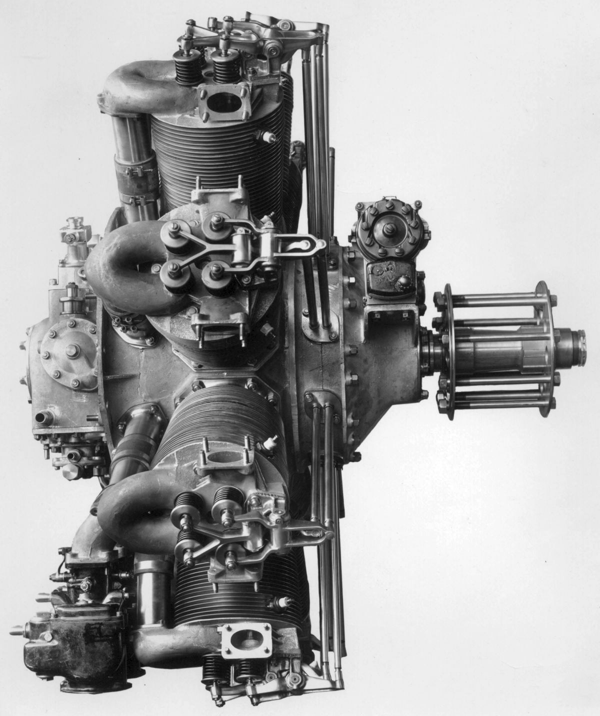
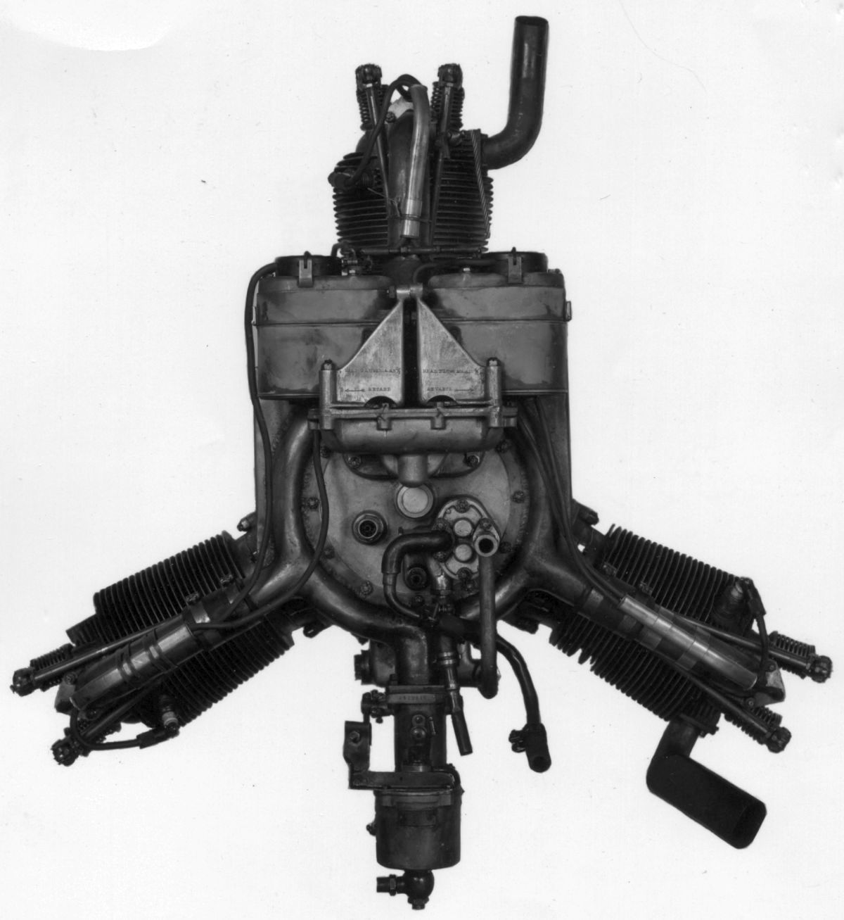
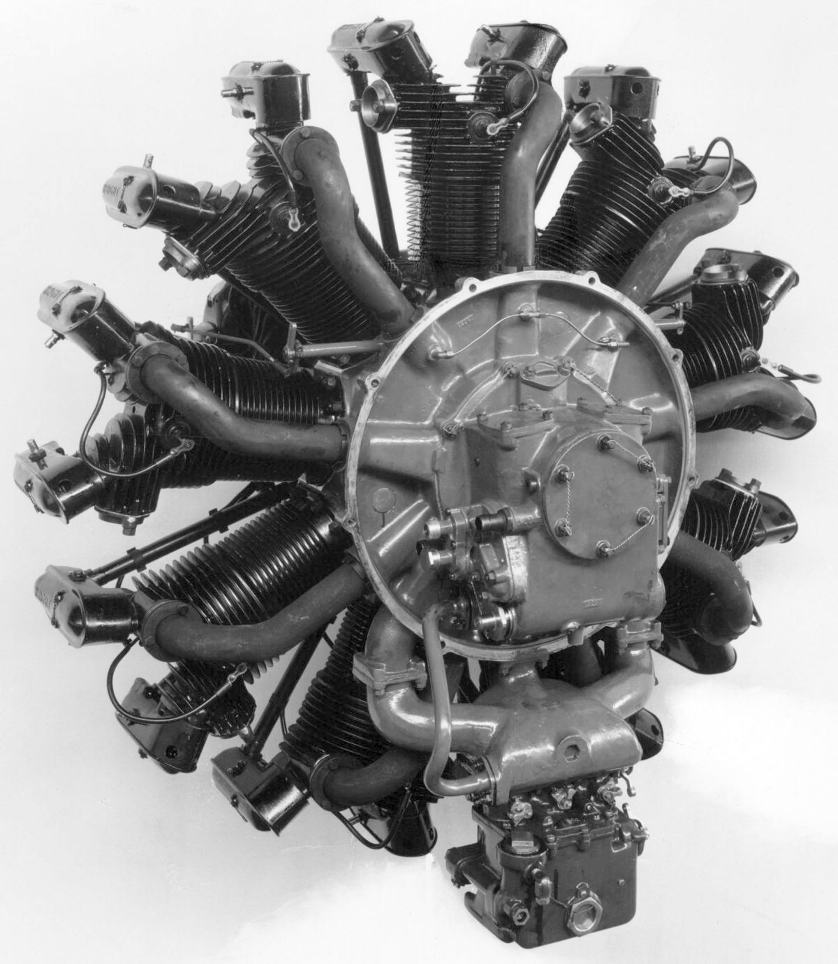
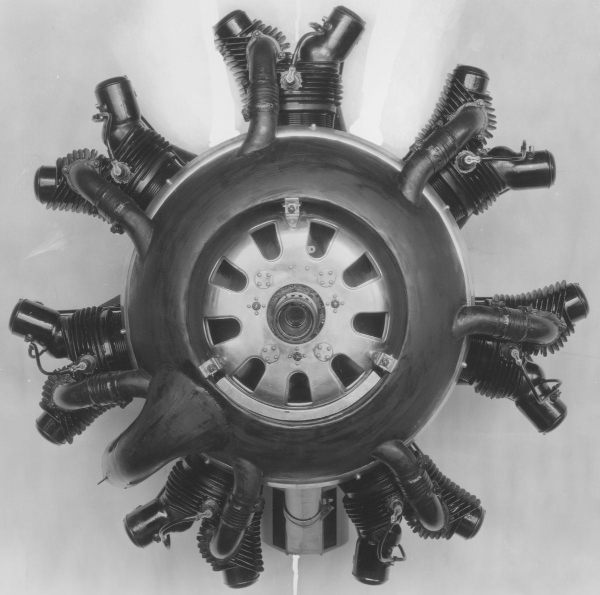
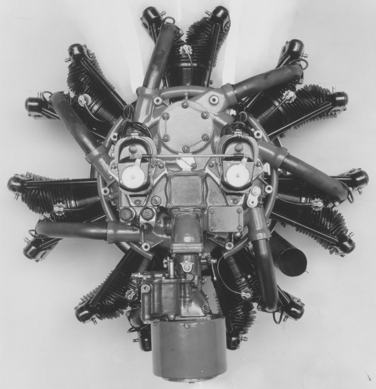
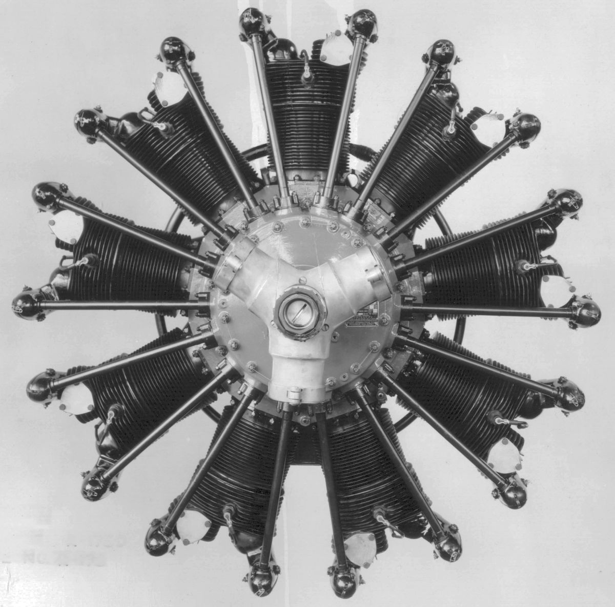
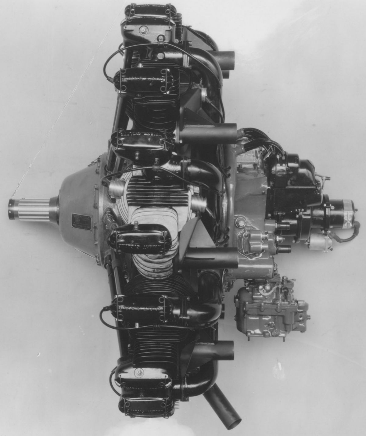
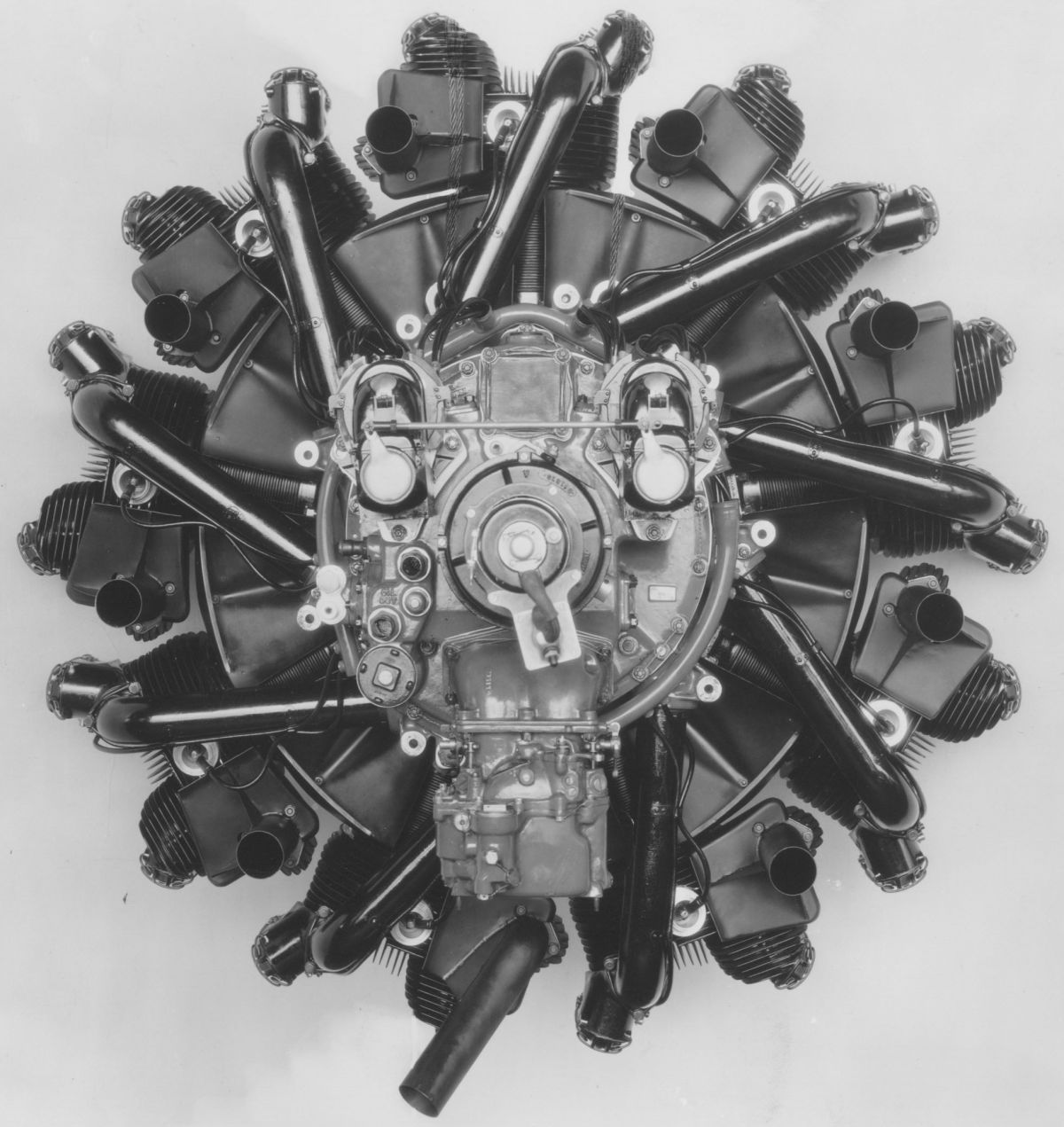
The Wright Cyclone engine series started in 1924 when the Navy Department contracted with WAC for an air-cooled radial nine engine of approximately the same displacement as the water-cooled Liberty L-12. The first Cyclone, known as the P-1, had a 6.000" (132.40 m ) bore, 6.500" (165.10 mm) stroke and 1,654 in³ (27.105 l) displacement. It produced 406 hp at 1,650 rpm and weighed 812 lb (368 kg).
In contrast to earlier WAC radials the P-1's magnetos were at the engine rear. Endeavoring to keep the Cyclone diameter the same as the Whirlwind, a unique valve mechanism was employed. This arrangement was not satisfactory as it did not appear in later Cyclones. The valves were located in a plane through the crankshaft, the exhaust being inclined 45° forward to the cylinder axis and the inlet 45° aft. With the cam mechanism at the engine front, the exhaust valve was operated by a push rod and rocker arm, while the inlet valve was operated by a push rod, bell crank, pull rod extending across the top of the cylinder, and a rocker arm. The cylinders were otherwise conventional, with cast aluminum-alloy heads that were screwed and shrunk onto forged steel barrels with integrally-machined cooling fins.
The articulated connecting rod system used a master rod whose big end had a white-metal-lined bearing, The link rods had bronze bushings for the piston and knuckle pins. Yhree Stromberg carburetors supplied the mixture to an induction system consisting of three independent three-cylinder manifolds. Two Scintilla magnetos furnished dual ignition.
 |
 |
 |
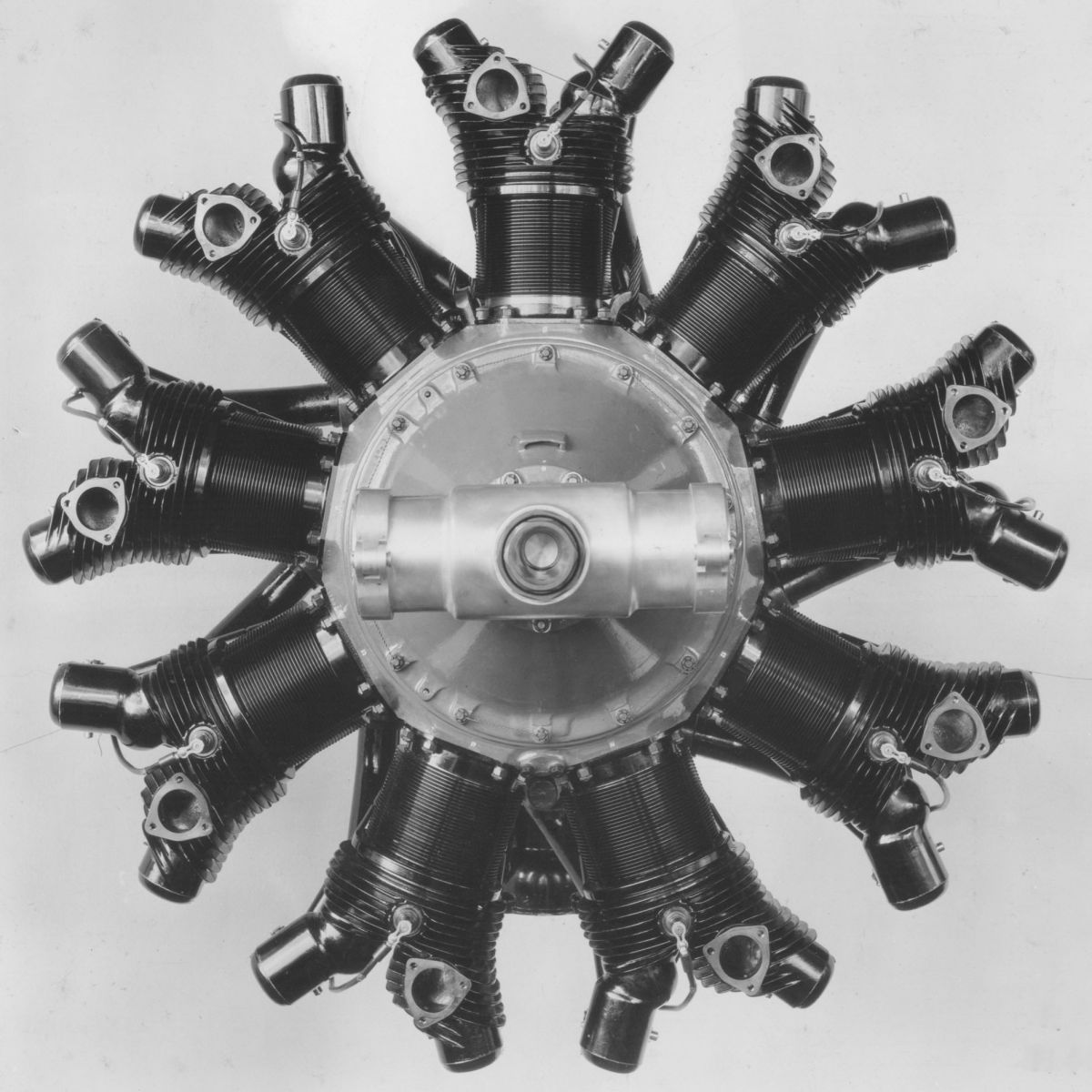
| WAC P-2 (NARA) | ||
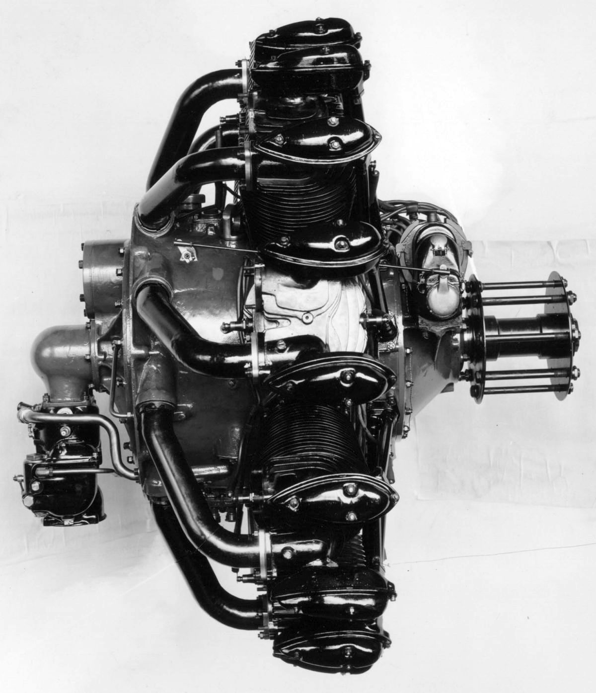
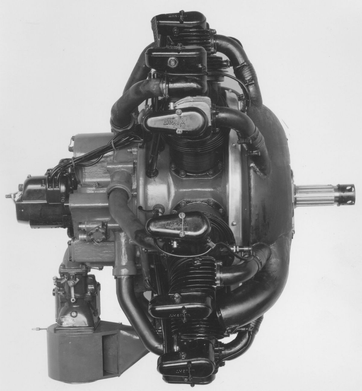
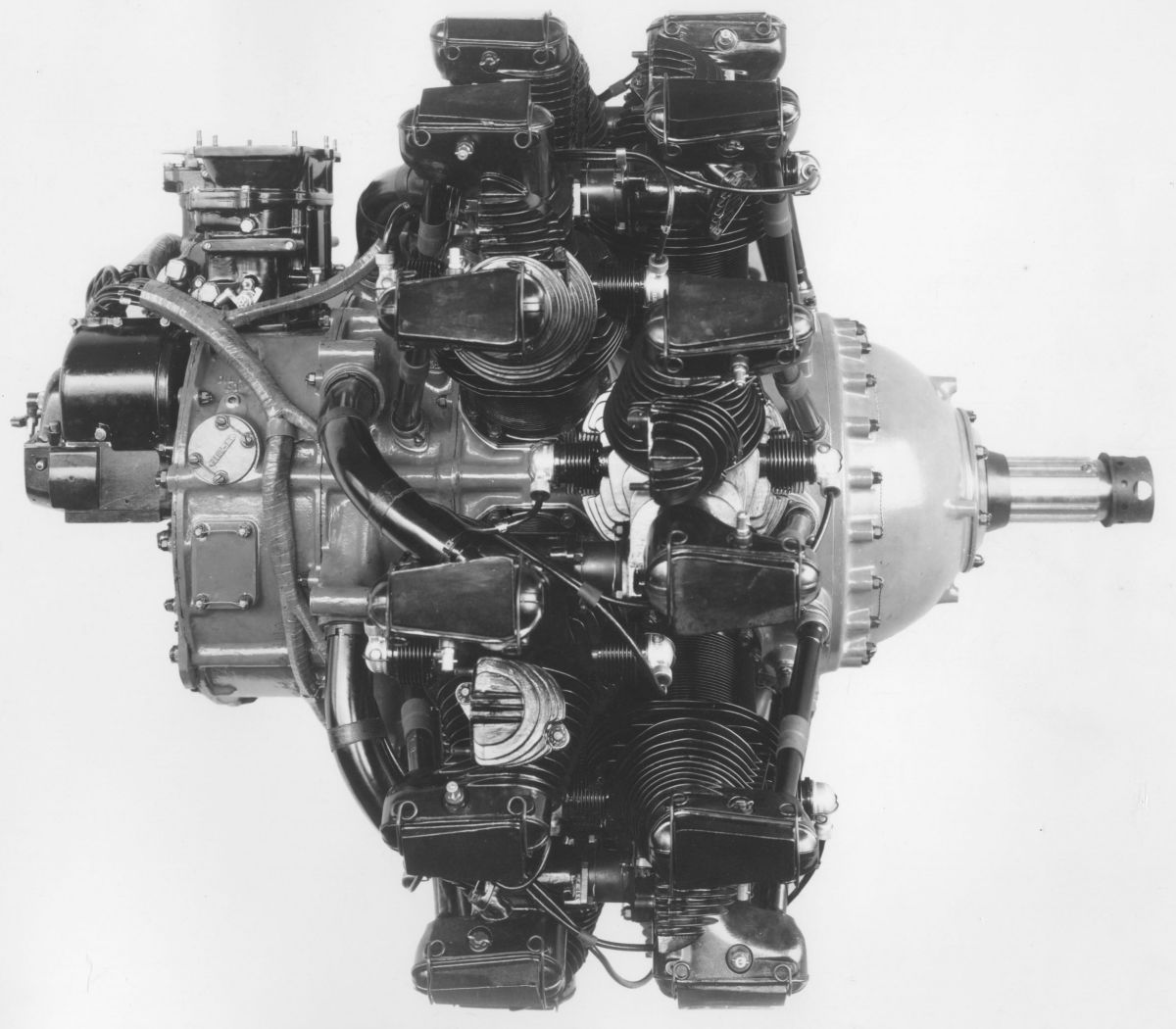
The Wright P-2, second in the Cyclone series, appeared in 1926. This was the first WAC air-cooled radial with a built-in gear-driven supercharger. With the same 6.000" (132.40 m ) bore, 6.500" (165.10 mm) stroke and 1,654 in³ (27.105 l) displacement as the P-1, the P-2 developed 435 hp at 1,800 rpm and 500 hp at 1,900 rpm. Fuel and oil consumptions were 0.56 and 0.04 lb/hp/hr. Dry weight was 851 lb (386 kg), diameter was 51.5" (1,308 mm) and length was 47.9375" (1,218 mm).
 |
 |
 |
 |
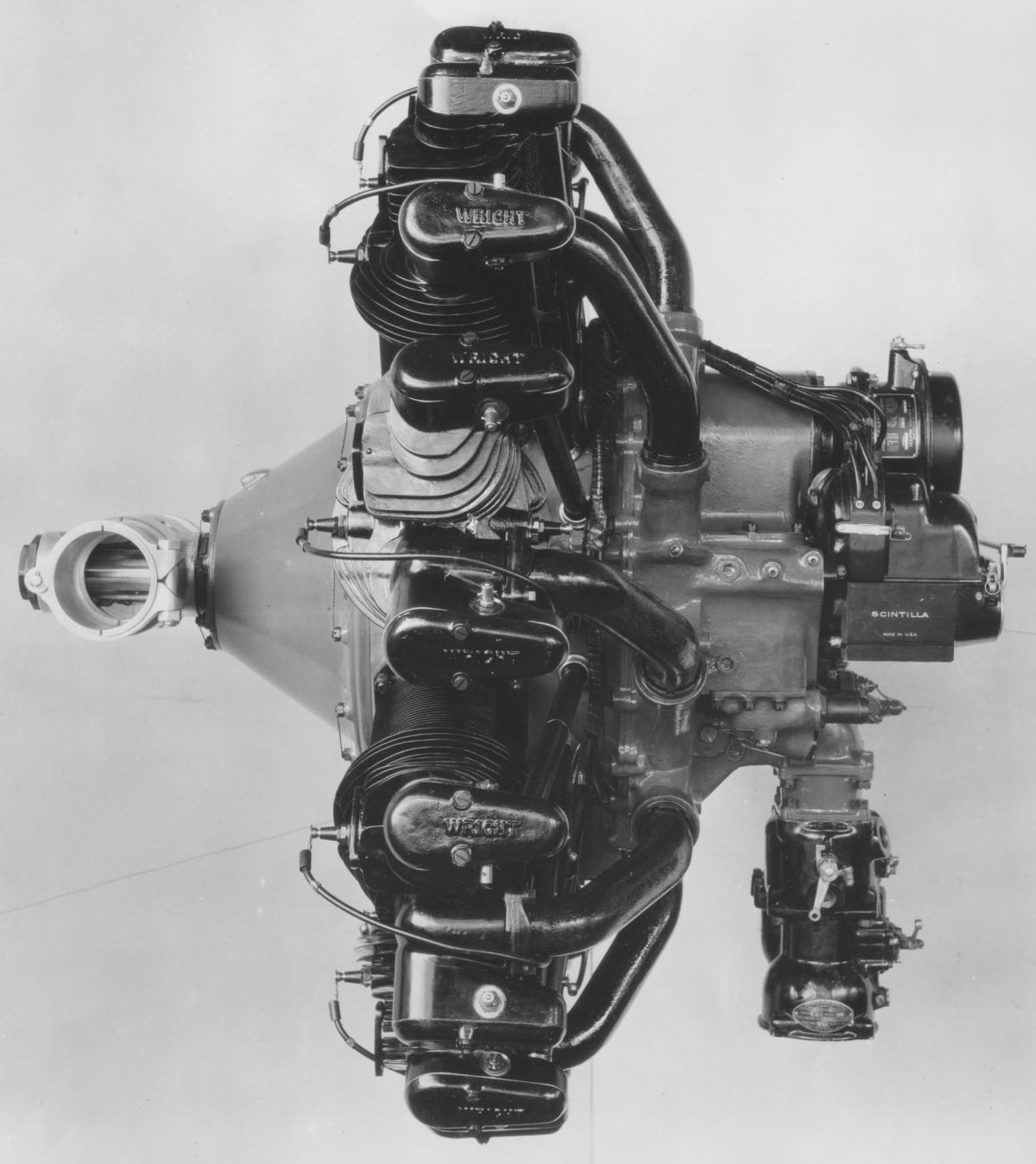
| WAC R-1750 (NARA) | |||
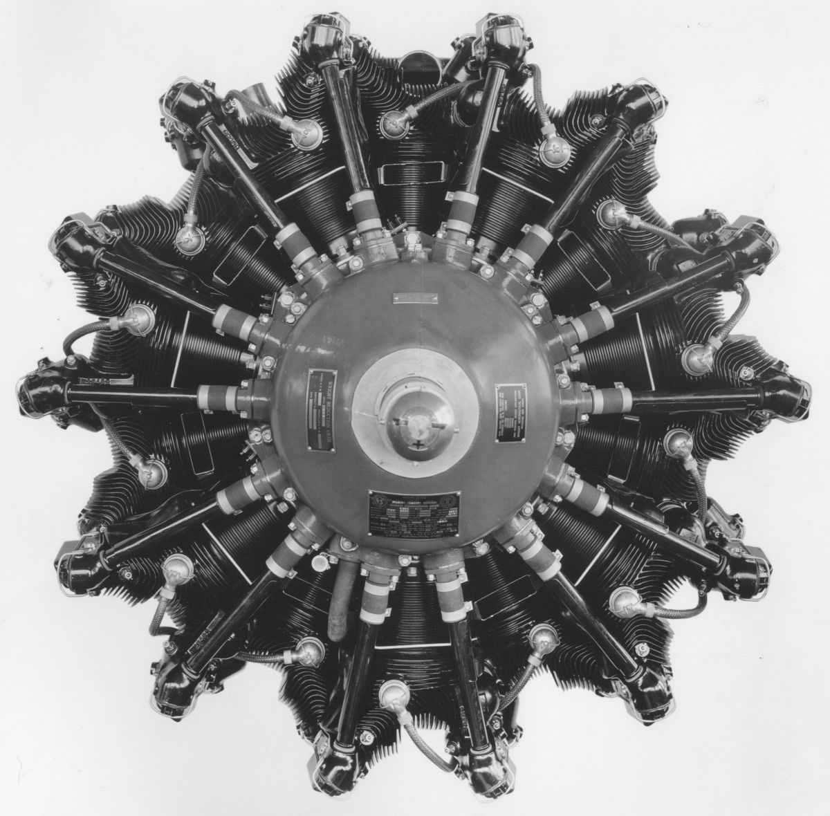
The R-1750 Cyclone passed a 50-hr service type test during 1927 and was undoubtedly intended to best the newly-minted Pratt & Whitney Hornet A. Keeping the same 6.000" (132.40 m ) bore as the P-1 and P-2, the R-1750's stroke was increased to 6.875" 174.63 mm), resulting in a 1,749.47 in³ (28.669 l) displacement and 5.0:1 compression ratio. Rated 525 hp at 1,900 rpm, R-1750 was awarded ATC No. 17 on 26 Jan 1929. Fuel and oil consumptions were 0.60 and 0.035 lb/hp/hr. Dry weight was 760 lb (345 kg), diameter was 53.9375" (1,370 mm) and length, without starter, was 39.25" (970 mm).
A cast aluminum-alloy cylinder head was screwed and shrunk onto an open-ended steel cylinder barrel with integrally machined cooling fins. The inlet ports faced aft and the exhaust ports faced forward. The inclined valves were actuated by a cam ring at the engine front driving fully enclosed push rods and rocker arms running on ball bearings. The rocker arms . Tulip-type valves were used, with the inlet having a solid stem and the exhaust a hollow stem containing a special salt compound for valve cooling. The single-throw crankshaft was made in two sections to accommodate a one-piece master rod fitted with a steel-backed bearing. The aluminum-alloy pistons were cross ribbed under the heads and fitted with full-floating hollow piston pins. The crankcase was composed of five aluminum-alloy castings. Except for the cam mechanism in the front-intermediate section, all accessory drives, including the magnetos, oil and fuel pumps, generator, and rotor induction system, were in the rear section. The fuel mixture was supplied by the a double-throat Stromberg carburetor mounted on the rear section, which fed the rotary impeller that distributed the air/fuel mixture evenly to all cylinders through pipes via a diffuser. The dry-sump pressure-fed lubricating system used gear pumps. Two Scintilla magnetos provided dual ignition.
ATC No. 17 was revised to include the Cyclone R-1750A, R-1750B, R-1750C, R-1750D and R-1750E. These were refined models, each incorporating changes of sufficient import to require new type designations. The R-1750E cylinders had side-facing exhaust ports, which facilitated installing either front or rear exhaust collectors. These cylinders also had an improved fin arrangement that provided better cooling. The compression ratio was increased to 5.1:1, although the rated output remained the same. The complete dry weight (without special equipment) was 835 lb (379 kg), diameter was 54.6875" (1,389 mm) and length was 43.844" (1,114 mm).
The R-1750EG was an R-1750E with propeller reduction gears. It had the same displacement and compression ratio and was rated 525 hp at 1,900 rpm. Fuel and oil consumptions were 0.55 and .035 lb/hp/hr. With 1.58:1 reduction gearing its dry weight (less propeller hub and starter) was 895 lb (406 kg). Its mounting circle diameter was 23.375" (603.3 mm), its outside diameter was 54.6875" (1,389 mm) and its length (less starter) was 46.6875" (1,186 mm).
WAC built 568 R-1750 engines between 1927 and 1932.
 |
 |
 |
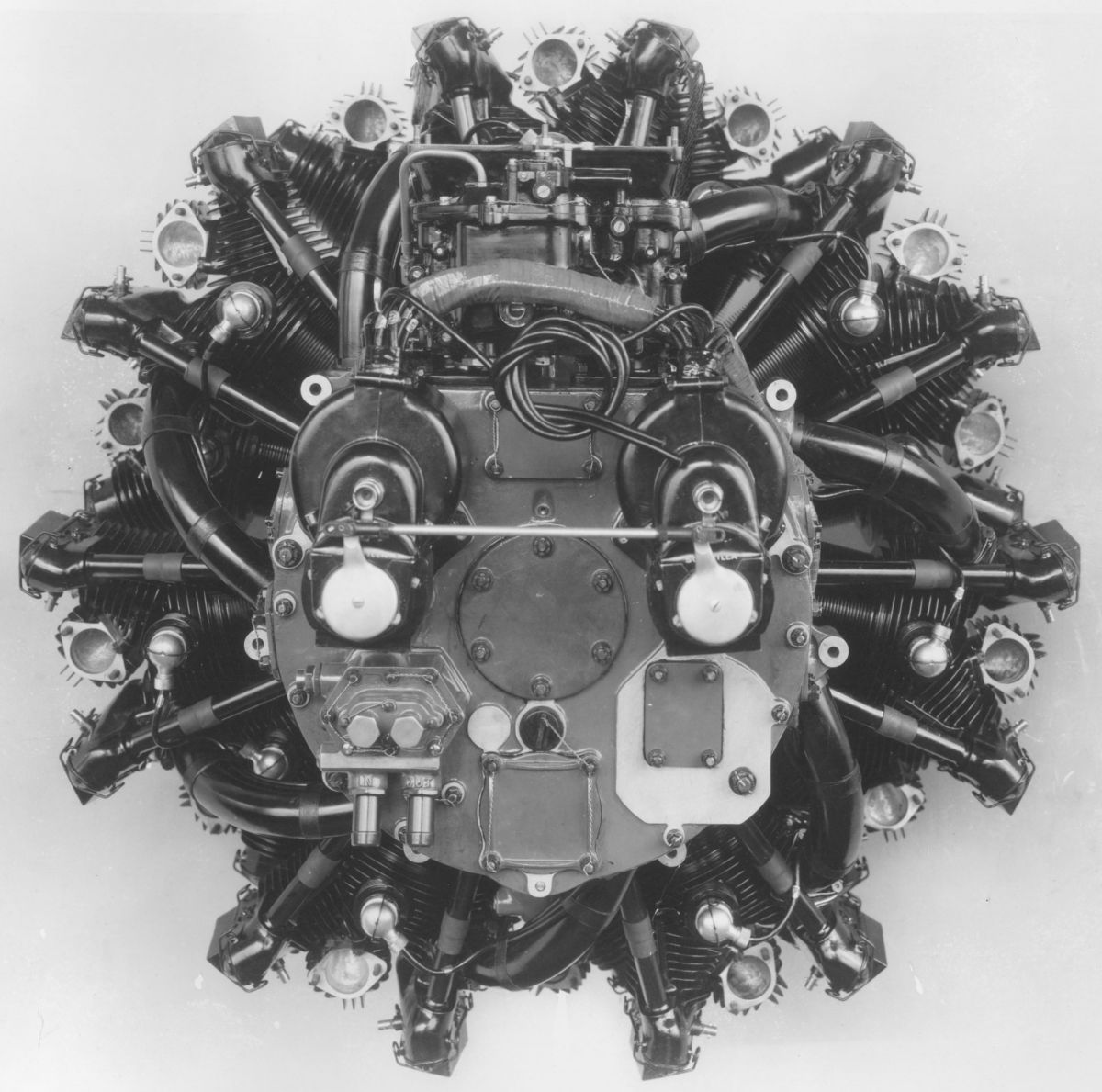
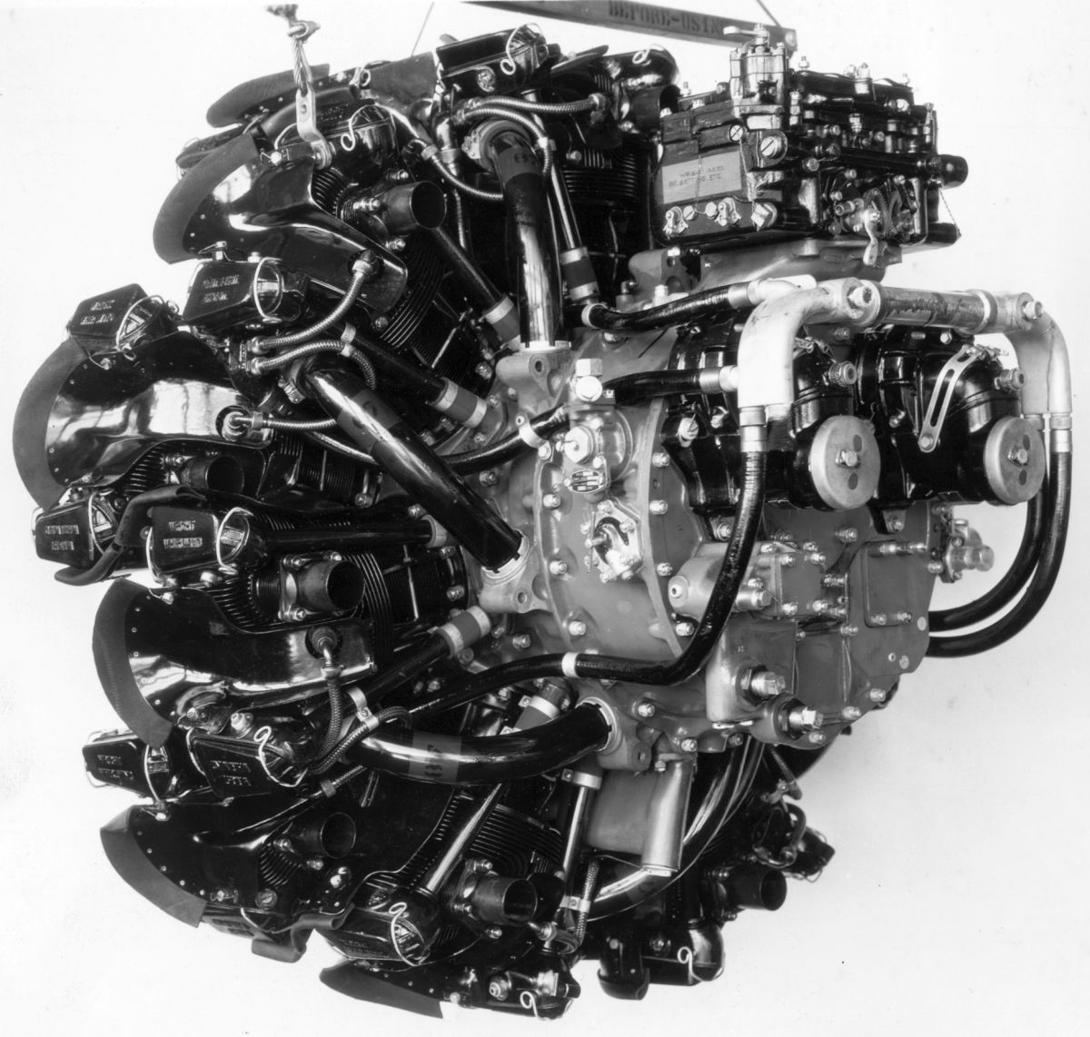
| WAC R-1820E (NARA) | ||
The Cyclone R-1820E received ATC No. 61 on 8 Sep 1930, rating it 575 hp at 1,900 rpm. A 21 Nov 1931 revision included the GR-1820E with either 1.58:1 or 2.0:1 propeller reduction gearing. In essence, this was an improved R-1750 with a 0.125" (3.175 mm) bore increase to 6.125" (155.58 mm). The stroke remained at 6.875" (174.63 mm) resulting in an 1,823.13 in³ (29.876 l) displacement. With a 5.0:1 compression ratio and 1:8.74 blower ratio, fuel and oil consumptions were 0.55 and 0.035 lb/hp/hr. Dry weight of the R-1820E, without starter, was 940 lb (426 kg); the GR-1820E weighed 974 lb (442 kg) with the 1.58:1 reduction ratio and 1,000 lb (454 kg) with the 2.0:1 ratio. Diameter was 54.6875" (1,389 mm) and length was 43.844" (1,114 mm).
R- and GR-1820E exhaust ports faced the cylinder side so that either front or rear exhaust collectors might be used. The cylinders were equipped with cooling baffles and individual spark-plug coolers. The rocker boxes were integrally cast with the aluminum alloy cylinder heads. Inlet valves opened 15° early and closed 45° late; exhaust valves opened 75° early and closed 25° late.
The R-1820F was an advanced design developed from the R-1820E. Bore, stroke and displacement remained the same, but the rating was increased to 645 hp at 1,900 rpm. ATC No. 93 was awarded on 7 Dec 1932. A 7 Feb 1933 revision included the GR-1820F with an 8:5 propeller reduction ratio. On 23 May 1933, the model designations were changed to read R-1820F-21 and GR-1820F-21. A 2 Aug 1933 revision approved 16:11 propeller reduction gearing.
As WAC gained experience with the Cyclone series in service and found new applications, it made continual performance, reliability improvements, and new features, including provisions for hydraulically-operated controllable-pitch propellers. The R-1820F series evolved into the R-1820G series and finally the R-1820H series. Production continued into 1964. More than 119,975 Cyclone engines were built by WAC and its numerous licensees. Later R-1820 engines are covered more extensively on this website and elsewhere.
Experiments
The early-to-mid 1930s saw development of three experimental WAC engines, two of which would be important to WAC’s future and one that proved yet again that radials really need an odd number of cylinders per row.
 |
 |
 |
| WAC GR-1510 (NARA) | ||
The R-1510 was a two-row air-cooled radial 14 with a 5.00" (127 mm) bore, 5.500" (139.7 mm) stroke and 1,511.89 in³ (24.775 l) displacement. All versions had a 45" (1,143 mm) diameter and required 87 octane fuel. This was WAC’s first attempt to build a double-row engine and was essentially a double R-760. WAC built 34 of all models listed below between 1931 and 1937. No type certificate was issued and no type test ever took place.
The GR1510-A1, with a 6.25:1 compression ratio, 1:5.95 supercharger ratio and 4:3 propeller reduction gear ratio had a 680 hp at 2,300 rpm takeoff rating, a 650 hp at 2,300 rpm normal rating and weighed 895 lb (406 kg). Its length was 49.53" (1,258 mm).
The SGR1510B1, with a 6.25:1 compression ratio, 1:5.95 supercharger ratio and 4:3 propeller reduction gear ratio had a 700 hp at 2,300 rpm takeoff rating, a 700 hp at 2,300 rpm normal rating and weighed 960 lb (435 kg). Its length was 49.56" (1,259 mm).
The GR1510C2, with a 7.0:1 compression ratio, 1:7.0 supercharger ratio and 4:3 propeller reduction gear ratio had a 670 hp at 2,400 rpm takeoff rating, a 590 hp at 2,400 rpm normal rating and weighed 1,025 lb (406 kg). Its length was 52.38" (1,330 mm).
 |
 |
 |
| WAC R-1670 (NARA) | ||
The R-1670 was a two-row air-cooled radial 14 with a 5.25" (127 mm) bore, 5.500" (139.7 mm) stroke and 1,666.86 in³ (27.315 l) displacement. All versions had a 45" (1,143 mm) diameter and required 87 octane fuel. This was a second attempt for WAC to build a double-row engine. The work took place between 1935 and 1936, and it may have been a precursor to WAC’s first successful two-row, the R-2600. No record exists of the number built; no type certificate was issued and no type test ever took place.
The GR1670A1, with a 7.0:1 compression ratio, 1:7.0 supercharger ratio and 16:11 propeller reduction gear ratio had a 830 hp at 2,400 rpm takeoff rating, a 775 hp at 2,400 rpm normal rating and weighed 1,160 lb (526 kg). Its length was 52.78" (1,341 mm).
The GR1670C2, with a 6.75:1 compression ratio, 1:5.75 supercharger ratio and 16:11 propeller reduction gear ratio had a 850 hp at 2,600 rpm takeoff rating, a 750 hp at 2,500 rpm normal rating and weighed 1,236 lb (561 kg). Its length was 53.56" (1,360 mm).
The GW2120 was an experimental geared liquid-cooled two-row radial 12 built for the U.S. Navy. This engine is discussed elsewhere on the AEHS website and by William Pearce. It, like its Curtiss H-1640 predecessor, was not a success.
Small Air-Cooled Engines
 |
 |
 |
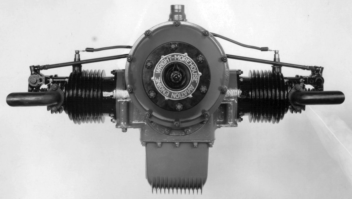
| Wright-Morehouse WM-80 (NARA) | ||
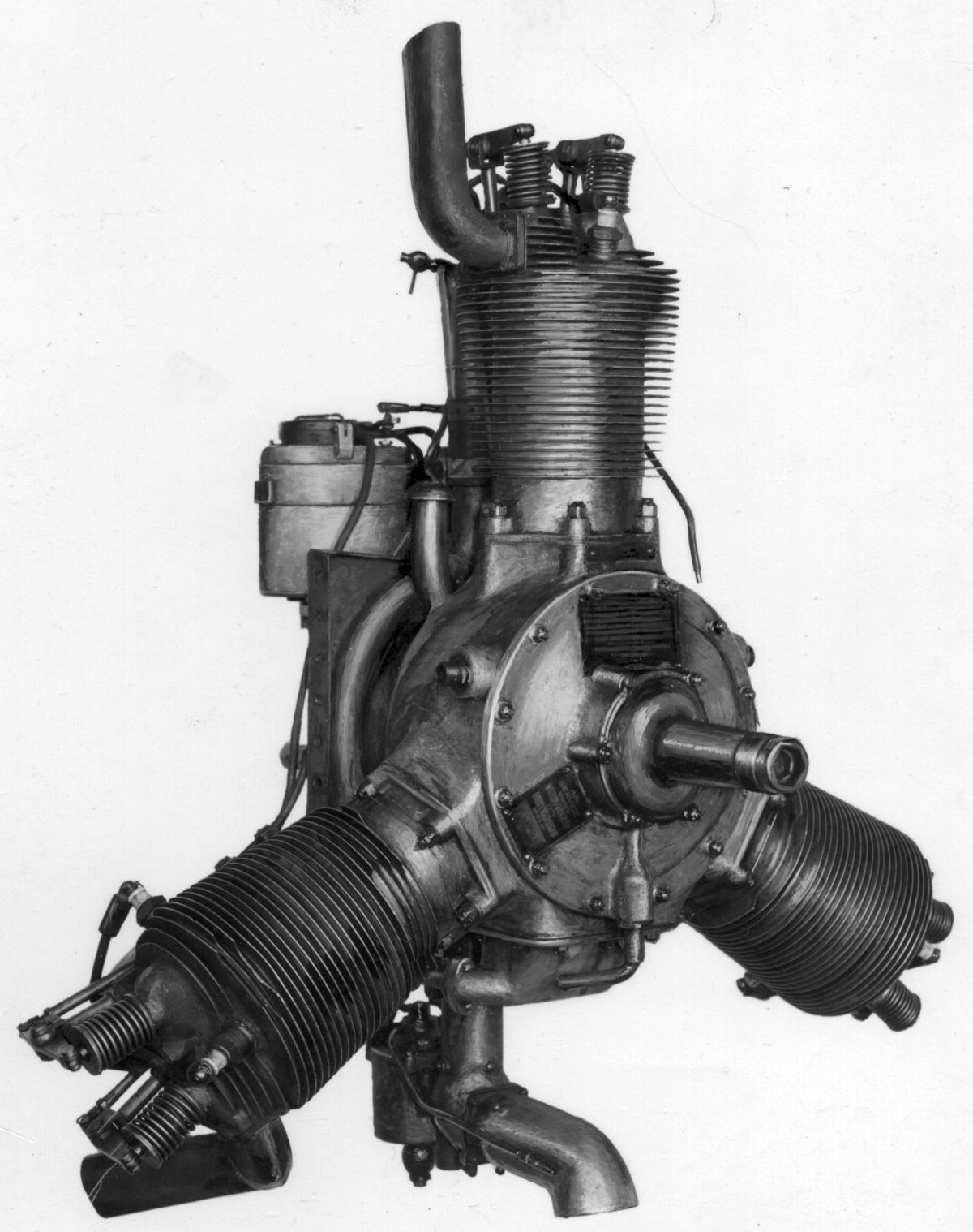
WAC manufactured the air-cooled Wright Morehouse opposed-twin, designed by Harold E. Morehouse at Dayton, Ohio after Morehouse joined the WAC engineering department in 1925. When WAC first acquired the Morehouse design, it announced that a double version also would be built. This four-cylinder design placed two twins one above the other using a common crankcase with the two crankshafts geared to a centrally-located propeller shaft. It developed 60 hp and weighed approximately 175 lb (79 kg). Its principal advantages were in reduced propeller speed and utilization of most existing parts. However, the proposed engine was never placed on the market. In early 1930 the Morehouse designs and manufacturing tooling were sold to the Lincoln Aircraft Corporation of Lincoln, Nebraska.
 |
 |
 |
| WAC IV-1456 (NARA) | ||
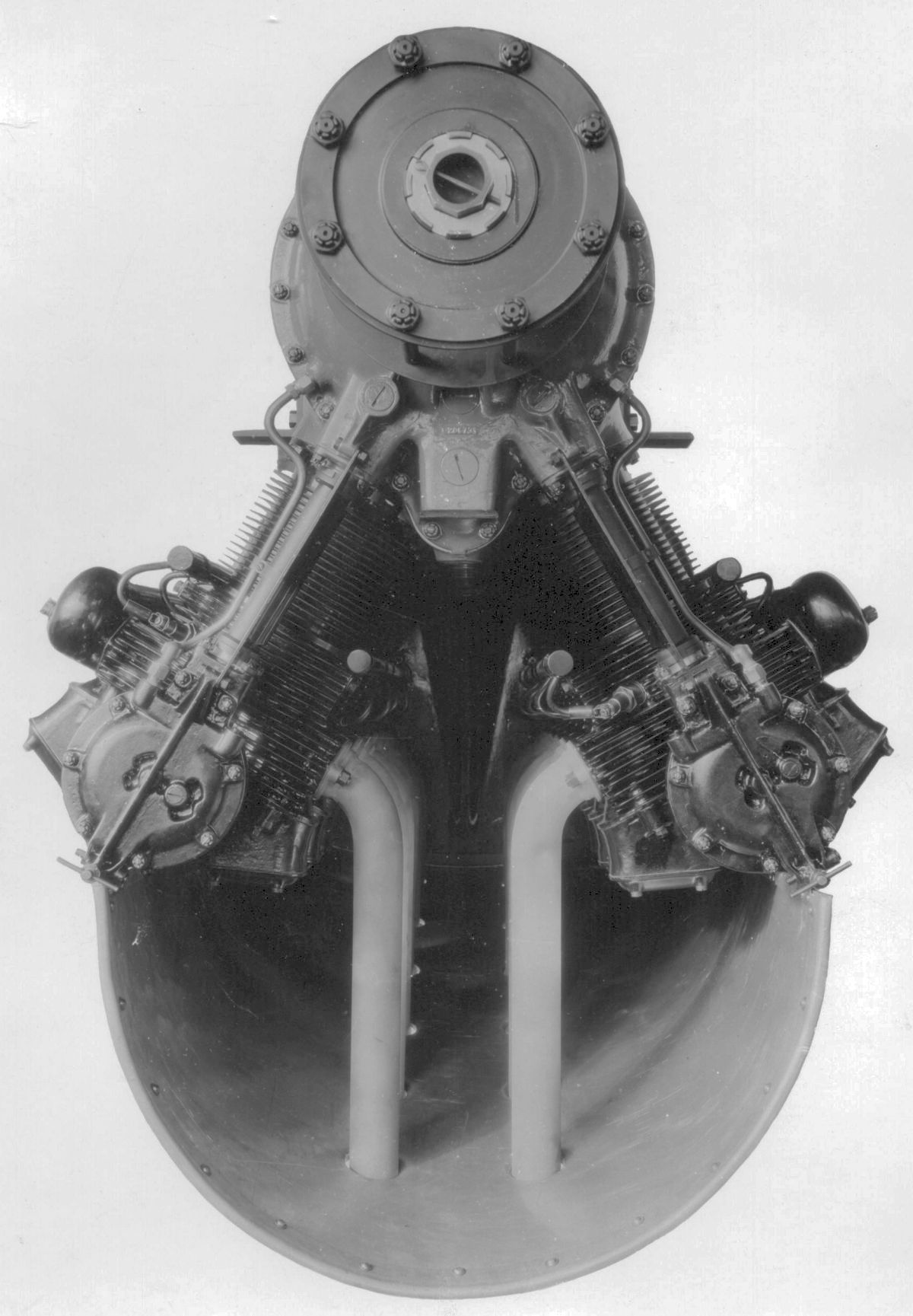
The IV-1456 was an experimental inverted air-cooled 60° V-12 that WAC developed for the Army Air Corps from 1930 to 1932. With a 4.875" (123.83 mm) bore, 6.500" (165.1 mm) stroke, 1,455.91 in³ (23.858 l) displacement and 5.3:1 compression ratio, it produced 525 hp at 2,300 rpm and weighed 925 lb (420 kg).
 |
 |
| Wright Gipsy (NARA) See also CAD Model |
|
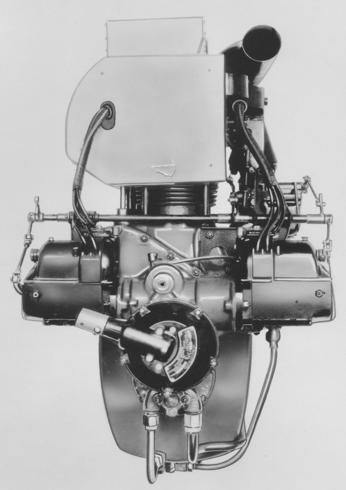
The Wright Gipsy was an air-cooled vertical four based heavily on the de Havilland Gipsy for which WAC acquired manufacturing rights and opened a separate factory in St. Louis, Missouri. Production was barely under way when depressed business conditions caused the plant to close. Most original Gipsy design features were retained, although changes were made to adapt the engine to American manufacturing methods. With a 4.500" (114.3 mm) bore, 5.000" (127 mm) stroke, 318.09 in³ (5.213 l) displacement and 5.0:1 compression ratio, it produced 85 hp at 1,900 rpm and 100 hp at 2,100 rpm. Fuel and oil consumptions were 0.55 and 0.01 lb/hp/hr. Dry weight was 285 lb (129 kg), length was 45.25" (1,149 mm), width was 20.09" (510 mm) and height was 34.1875" (868 mm). When ATC No. 40 was issued on 9 Jan 1930, it rated the Gipsy 90 hp at 1,950 rpm. A revision dated 27 Jul 1935 specified engines with serial numbers 50,000 to 50,338 and 51,000 to 51,050 are eligible under ATC No. 40; engines in the latter serial number block were assembled by the Menasco Manufacturing Company.
References
Angle, Glenn D, ed. Aerosphere 1939 (New York, New York: Aircraft Publications, 1940).
Anble, Glenn D, ed. Airplane Engine Encyclopedia (Dayton, Ohio: Otterbein Press, 1921).
Image Sources: A39 = Aerosphere 1939; AEE = Airplane Engine Encyclopedia; Flt = Flight Magazine; NARA = U.S. National Archives and Records Administration; UKNA = United Kingdom National Archives; Wiki = Wikimedia Commons (mouse over for details).
Send mail to
![]() with questions or comments about this web site.
with questions or comments about this web site.
![]()