Selected Early Engines W
Walter, Warner, Wells-Adams, Werner & Pfleiderer,
Western
Willis-DePalma, Winterthur,
Wolseley, Wright Brothers, Wright Aero
Compiled by Kimble D. McCutcheon
Published 10 Jul 2023; Revised 28 Aug 2023
Walter
Josef Walter established Walter Ltd. of Prague-Jinonice (A. S. Walter Tovarny na automobily a letecké motory) in 1896. Beginning with motorcycles and motor tricycles, Walter next introduced its own automobiles and later built Fiat 508, 514, 522 and 524 models under license. In 1922, Walter Aircraft Engines began manufacturing BMW IIIa and IV, and FIAT A.20, A.22, A.24 and A.25 aircraft engines under license as Walter W.III, W.IV, W.V, W.VI, W.VII and W.VIII. Air-cooled radials of its own design soon followed. Numerous other models followed, which kept the manufacturing operation active through WWII. General Electric purchased Walter Aircraft Engines in 2008.
|
|
|
| (Wiki) | (A39) | |
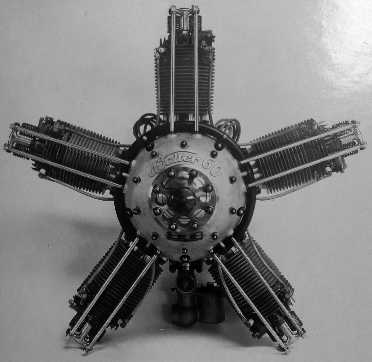
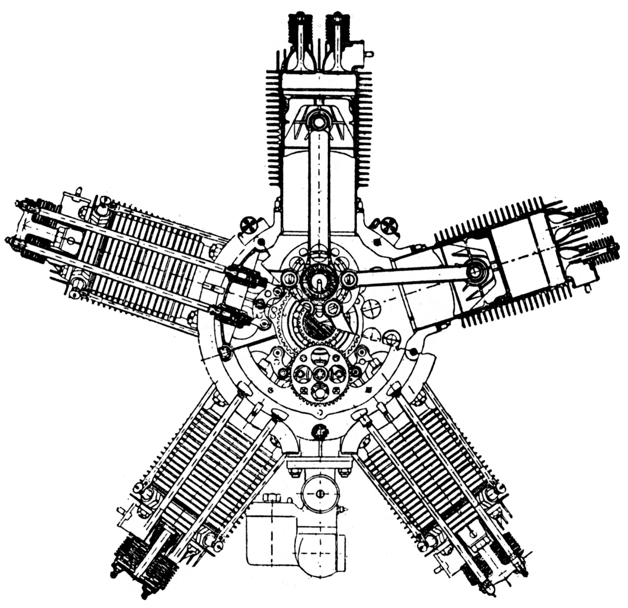
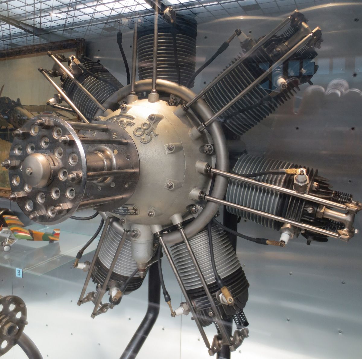
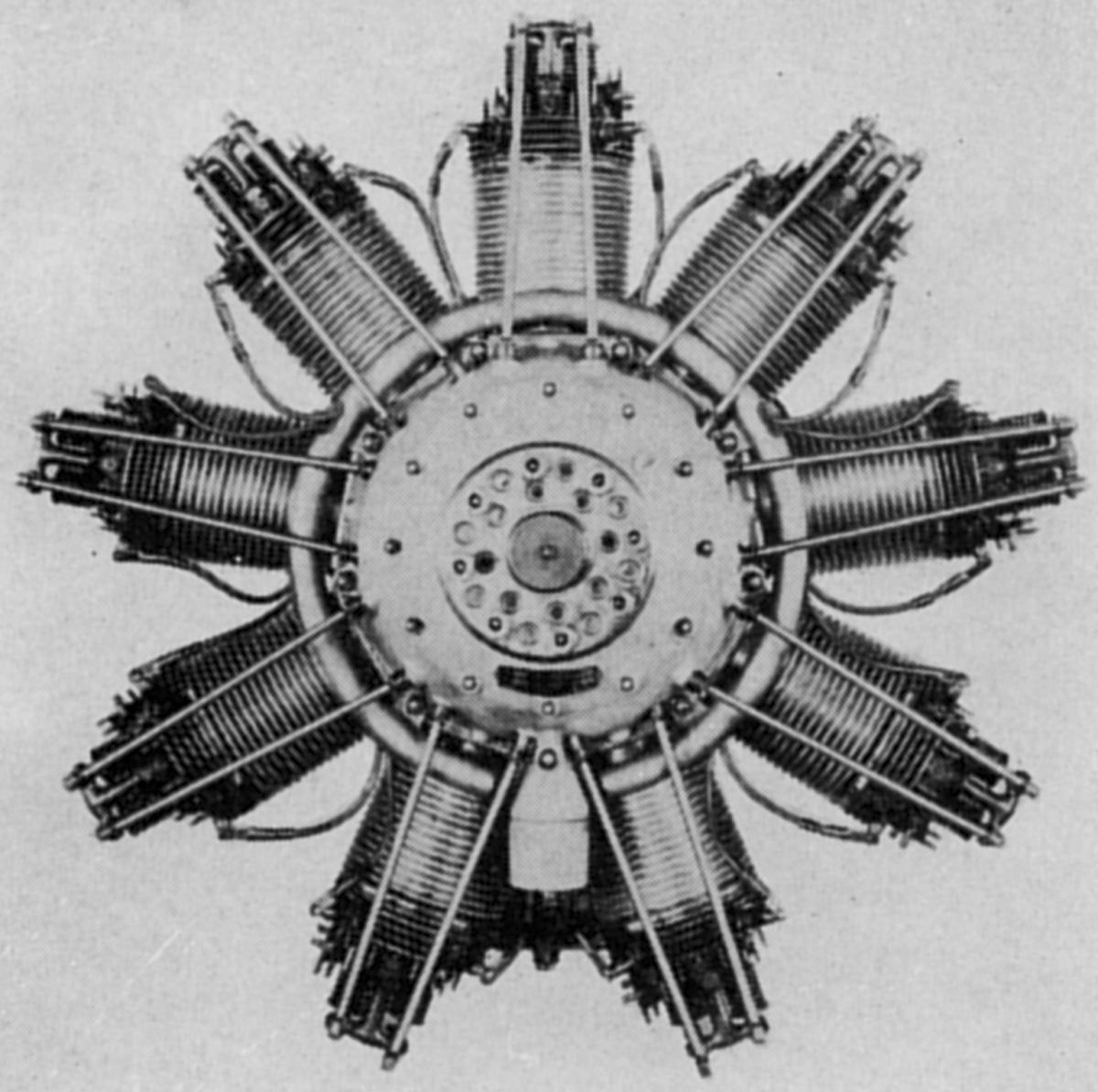
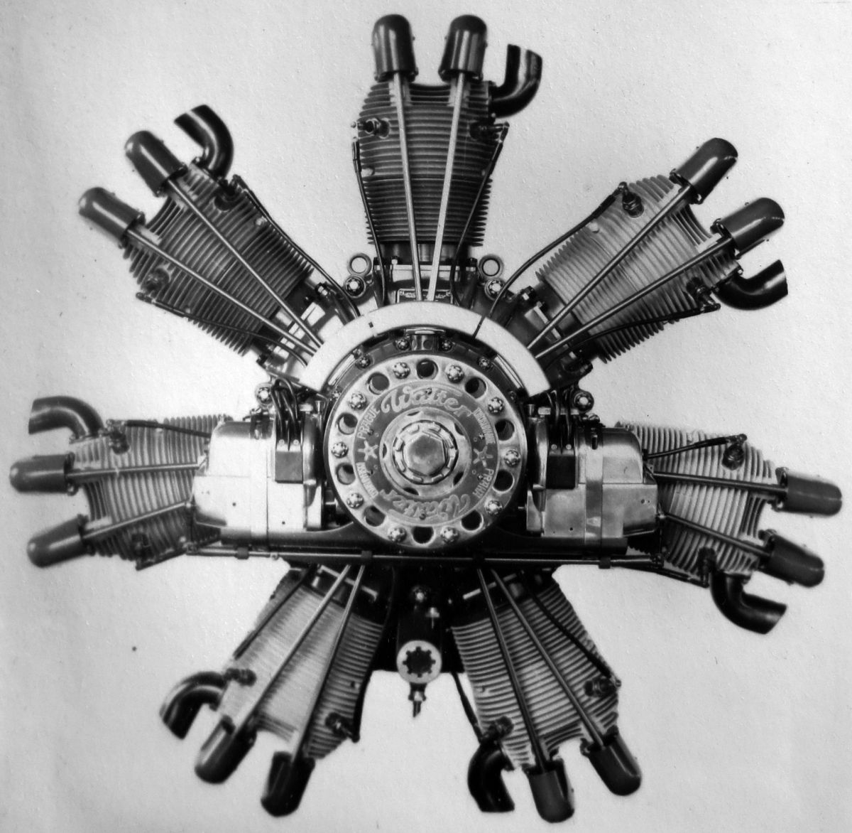
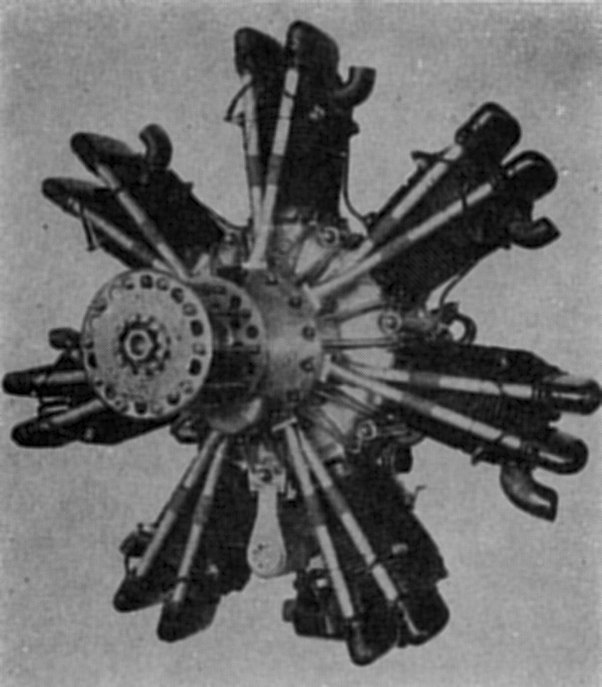
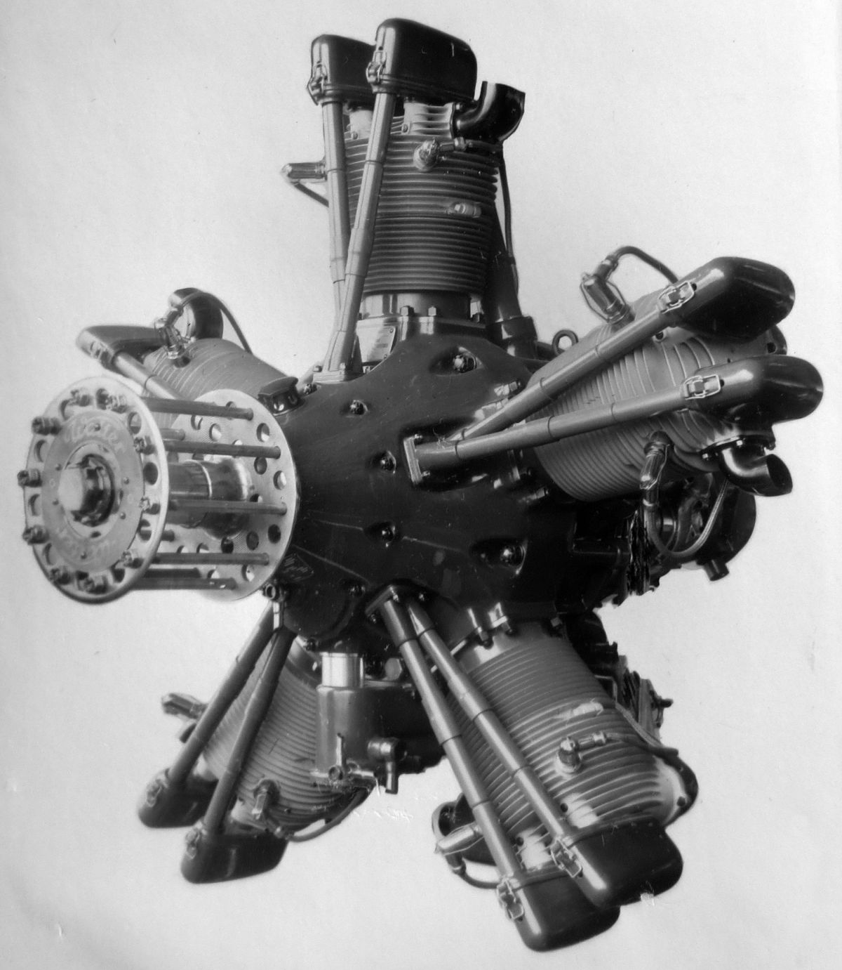
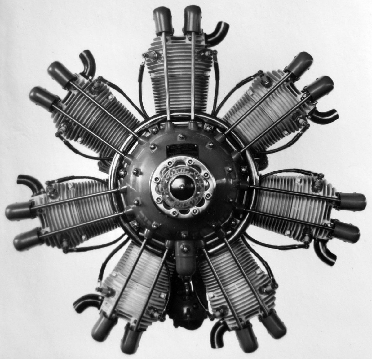
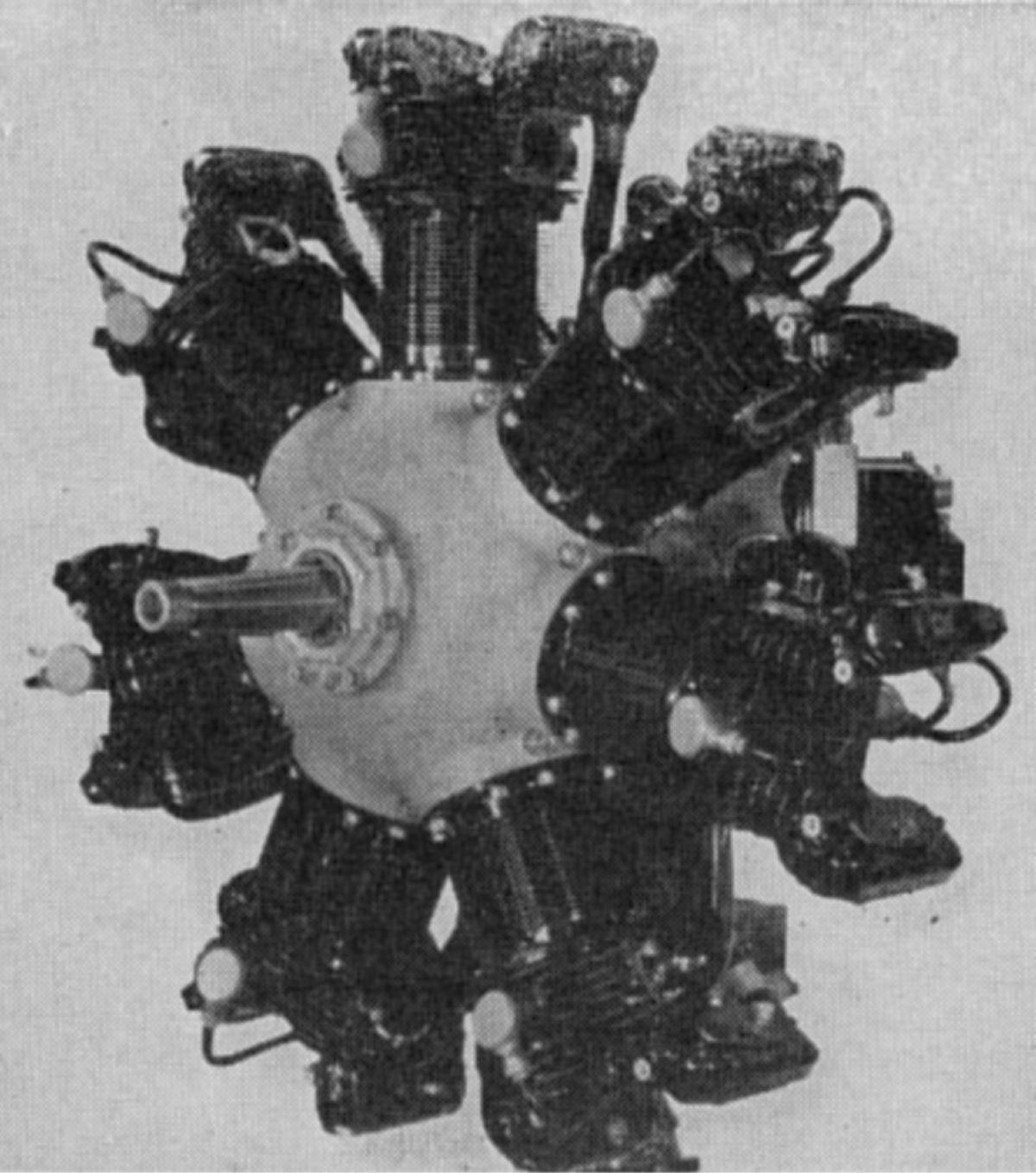
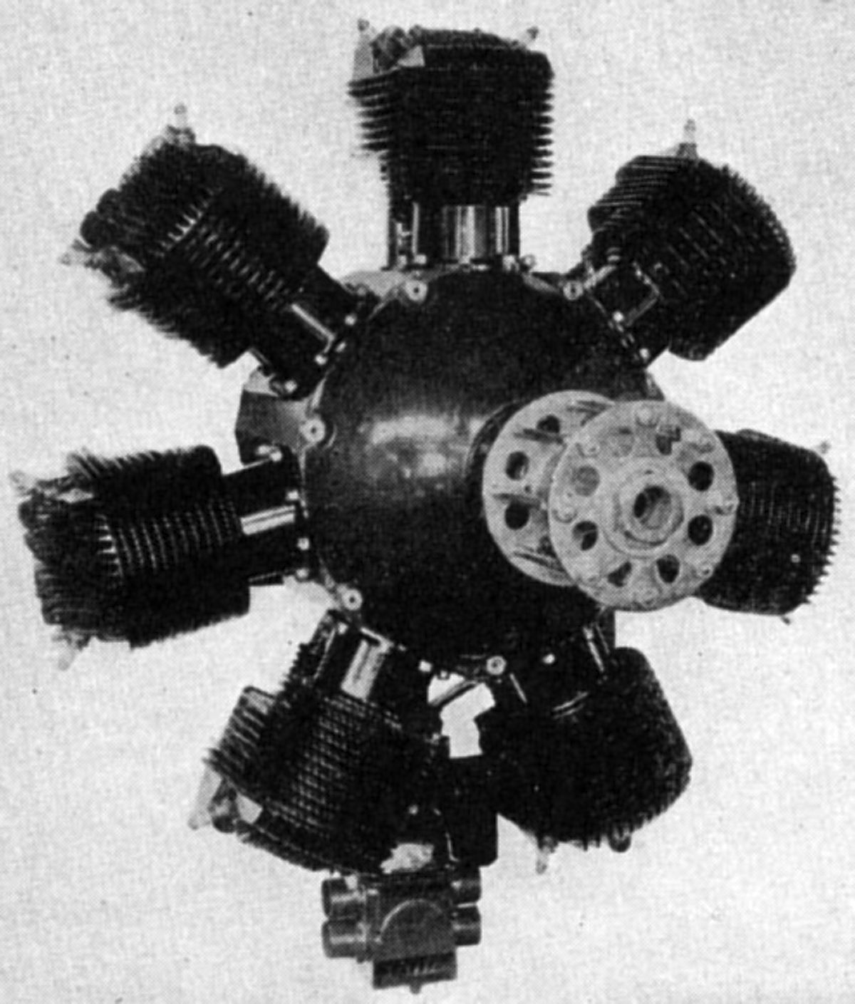
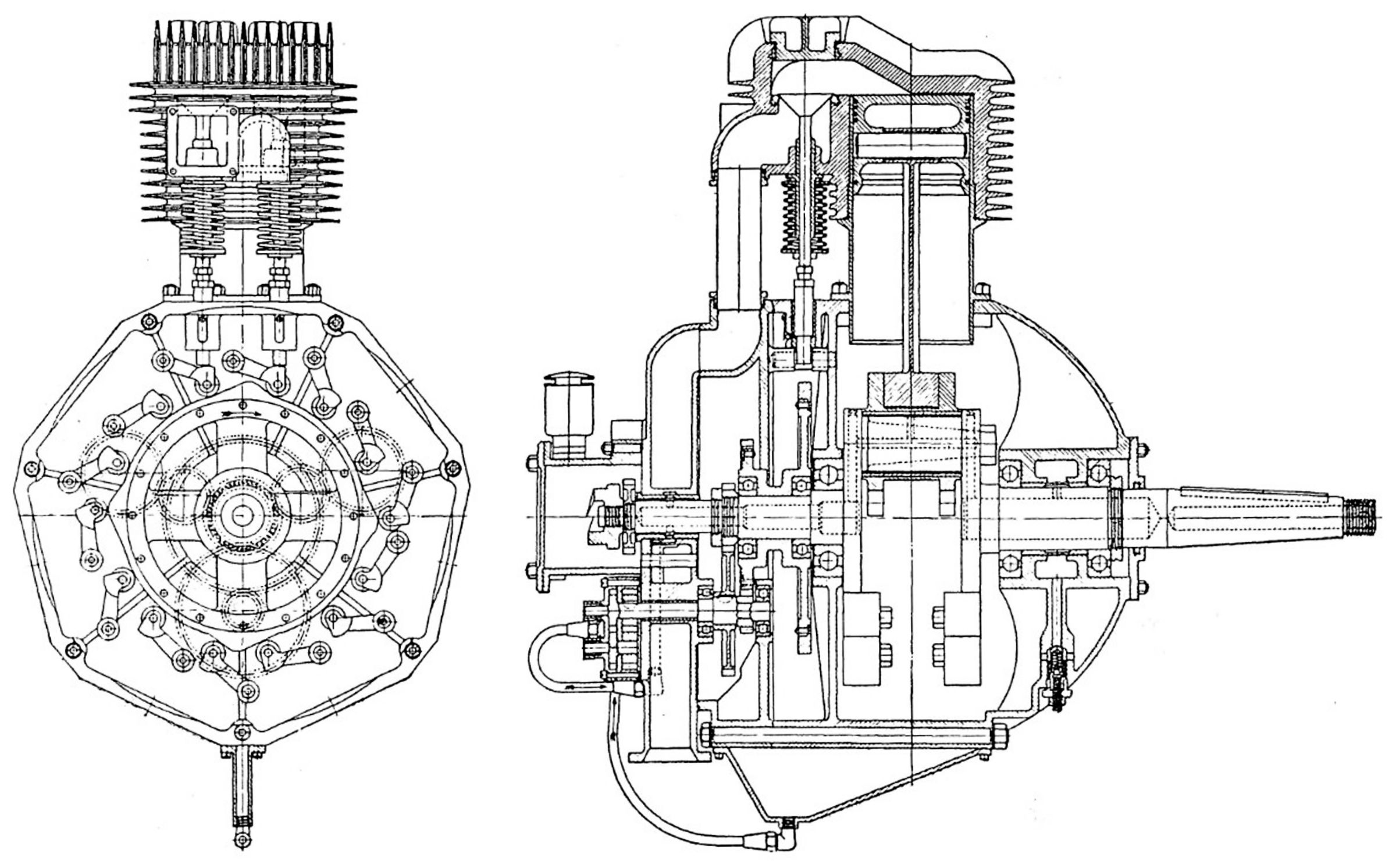
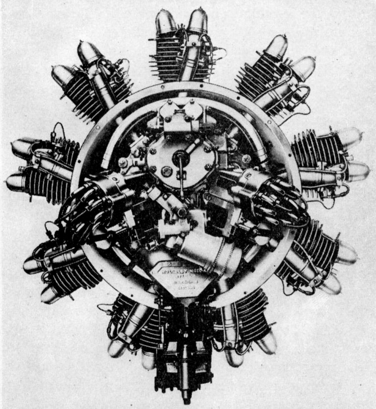
The NZ 60 (Novák-Zeithammer), a radial five introduced in 1922, was Walter’s first aircraft engine. With a 105 mm (4.134") bore, 120 mm (4.724") stroke, 4.48:1 compression ratio and 5.195 l (317.04 in³) displacement, it was rated 60 hp at 1,400 rpm but delivered 65 hp at 1,500 rpm and 75 hp at 1,750 rpm. Weight was 100 kg (220 lb). Diameter was 940 mm (37") and length was 853 mm (33.6"). Fuel and oil consumptions were reported as 0.52 and 0.03 lb/hp/hr.
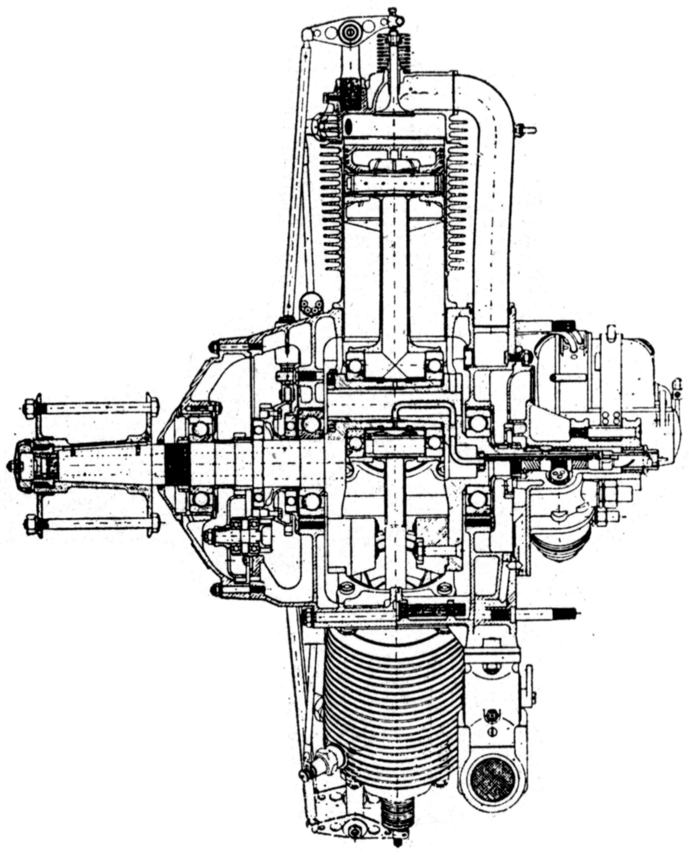
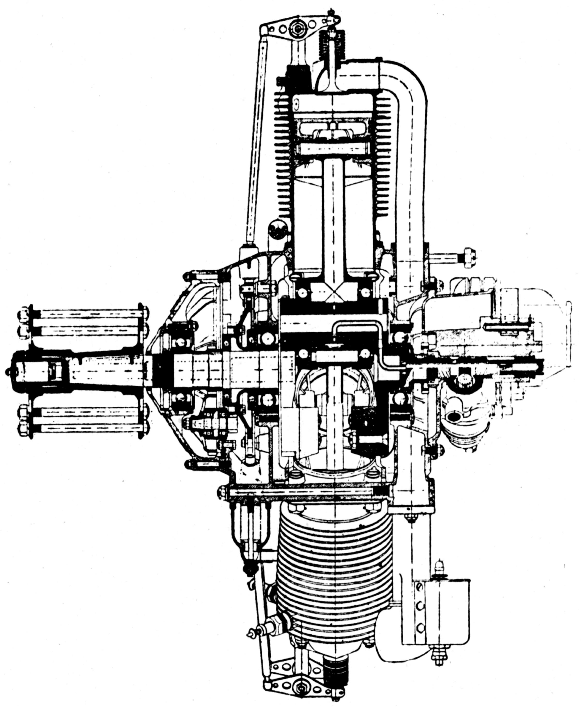
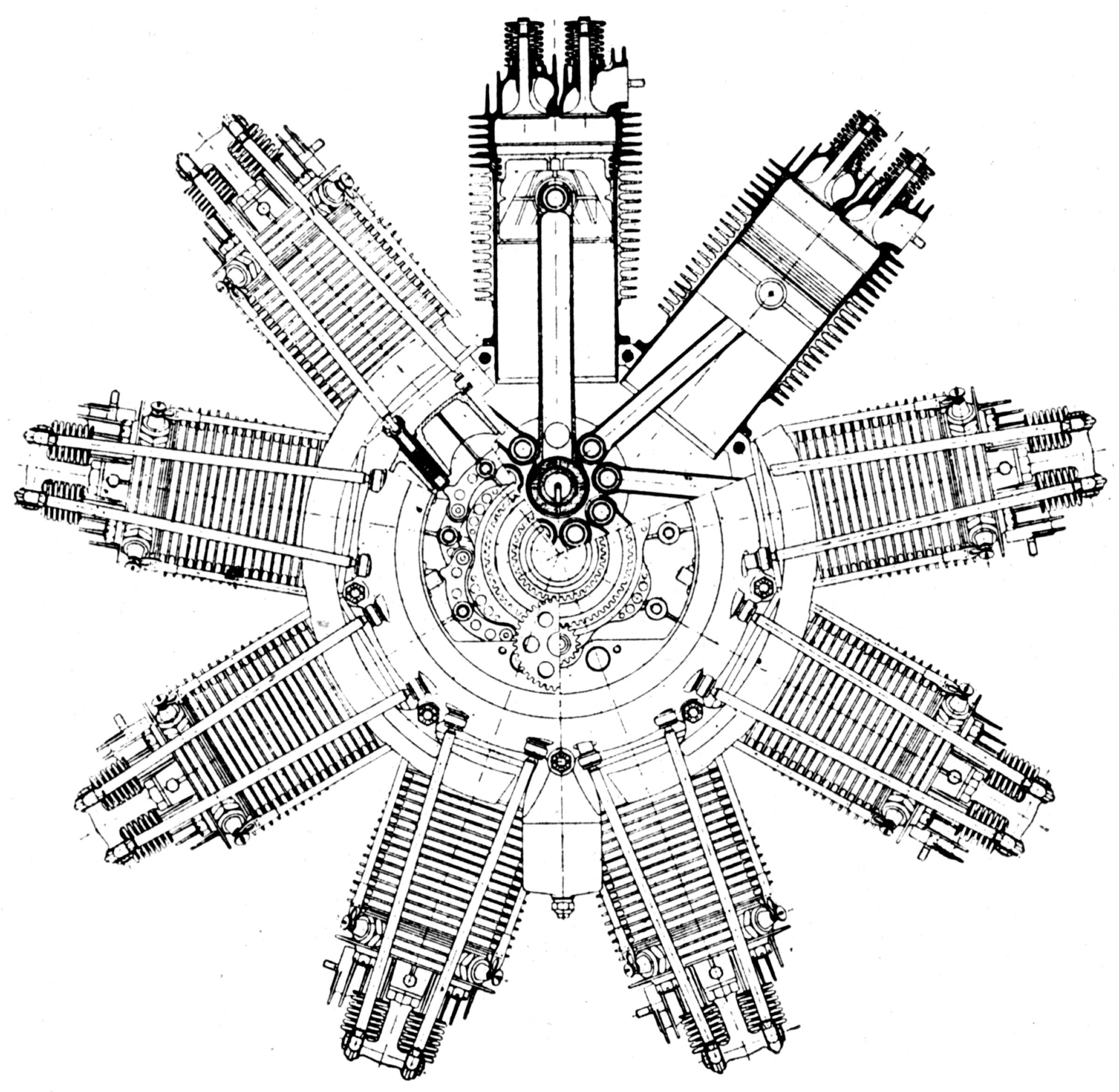
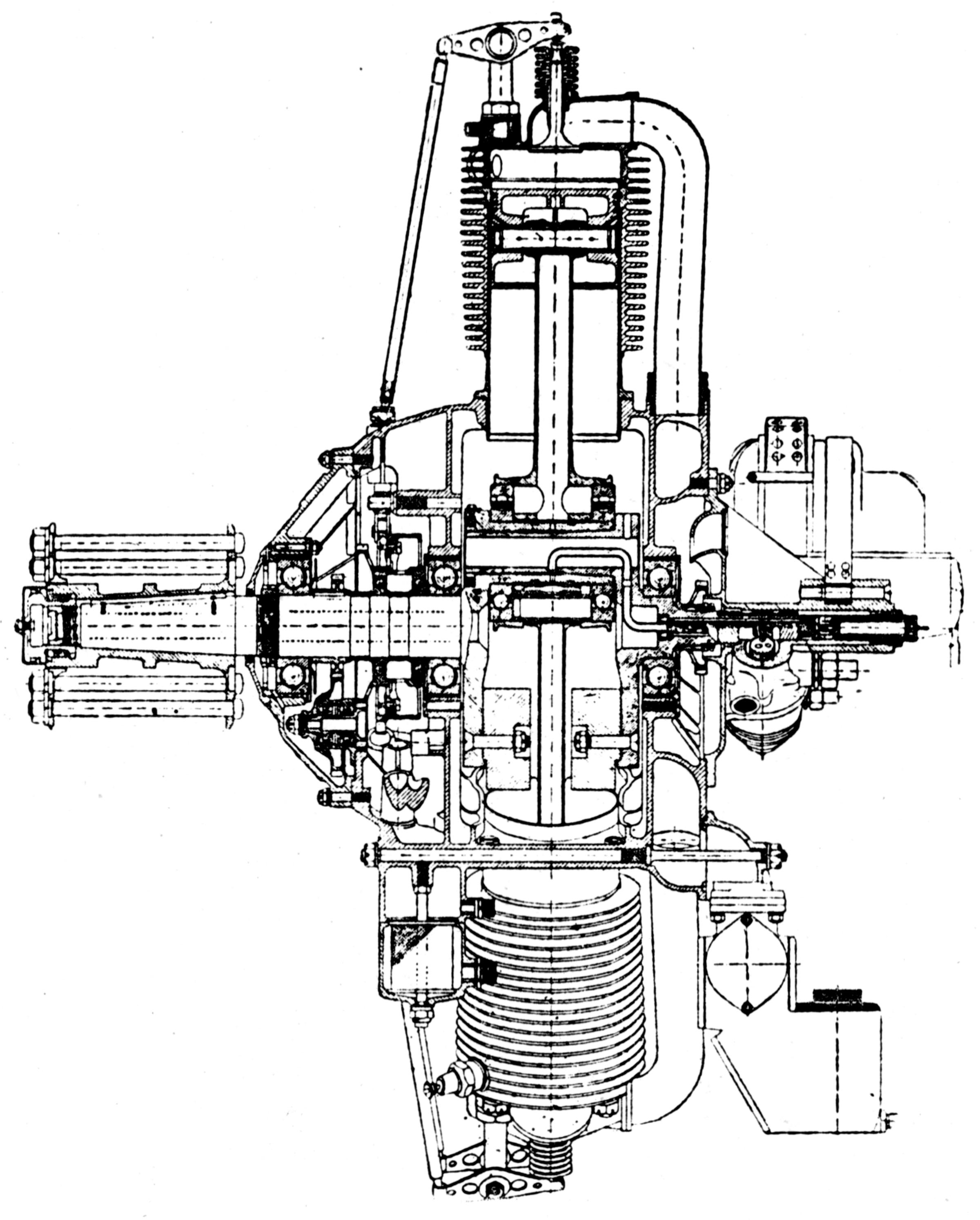
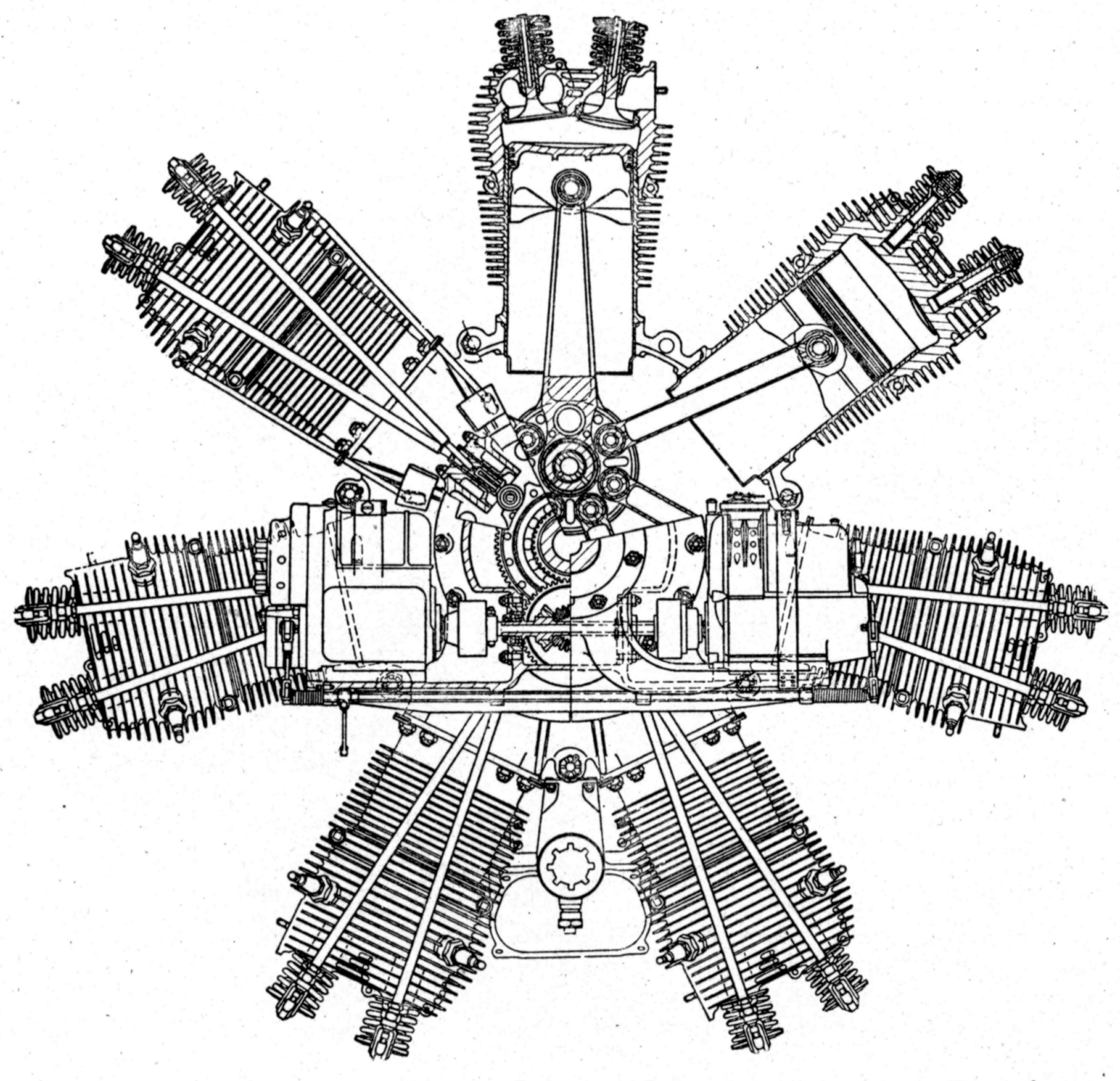
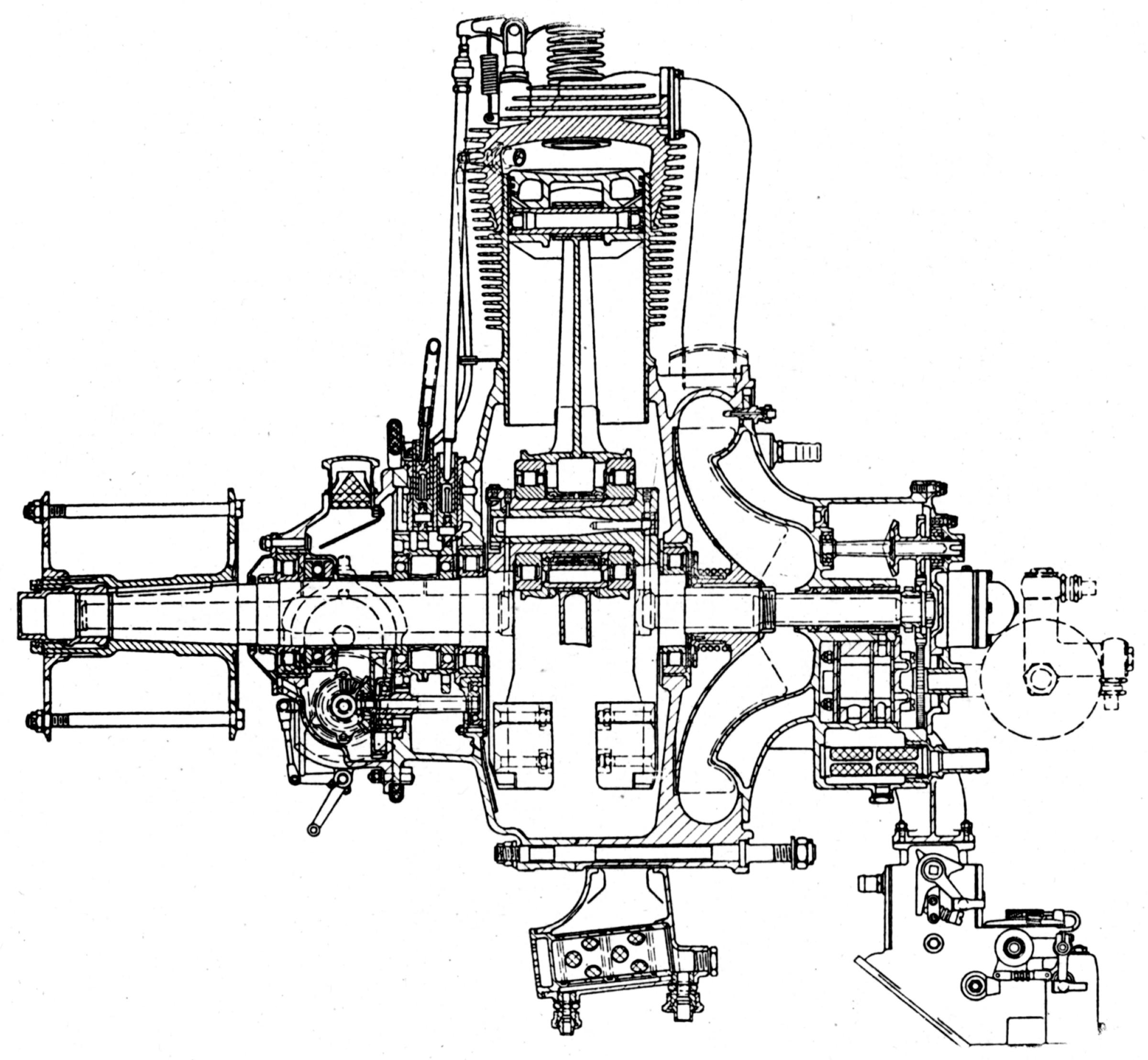
The NZ 60’s design concepts were used in other Walter radials. The cylinders consisted of zinc-coated steel barrels upon which aluminum cooling fins were cast. The detachable cast iron cylinder heads were held to the barrel by four studs. The valves seated directly upon the flat cylinder head and were operated by push rods and rocker arms from a cam ring on the engine front. The inlet port faced aft and the exhaust port to the side. The flat-headed aluminum alloy pistons had heavy axial ribs underneath and were fitted with three rings above the full-floating hollow piston-pin with aluminum plugs pressed into the ends. The articulated connecting rods all had tubular shank sections. The one-piece master rod big end ran on two ball bearings mounted on crankpin, which was integral with the crankshaft front section. The crankshaft aft section was joined to the front section by a taper, round key, and nut on crank-pin. The crankshaft ran on three ball bearings with the front bearing carrying the thrust load.
Two aluminum castings joined in the cylinder plane comprised the main crankcase The rear section contained cored passages for the induction manifold and a transverse wall forming a support for the rear crankshaft bearing. The front section had a corresponding transverse wall that supported the intermediate crankshaft bearing and the cam idler shaft. Both the cam ring and cam idler shaft were carried on two ball bearings. The aft cam ring bearings was supported on the crankshaft while the front one one fitted in an extension of the steel sleeve that supported the intermediate crankshaft bearing.
The NZ 60 crankcase nose section contained the cam mechanism and supported the front crankshaft bearing. The single-track three-lobed cam ring turned at one-sixth crankshaft speed and operated all the valves. A lever with a pivot located in the cylinder plane, carried rollers at each end that contact the the cam. Opposite the rollers on the ends of this lever were flat spots making contact with tappets containing coil springs and guided in bushings in the crankcase front half. The magnetos, oil pumps, and other accessory drives were located at the engine rear. Two Scintilla magnetos mounted in Vee arrangement supplied dual ignition. The NZ 60 mixture was furnished by a Solex or Zenith carburetors, while the larger engines used Zenith carburetors. The carburetors were mounted on the crankcase under side aft of the cylinders. Oil under pressure was delivered to the bearings by a special plunger pump.
 |
 |
 |
 |
| (A39) | (Wiki) | (A39) | |
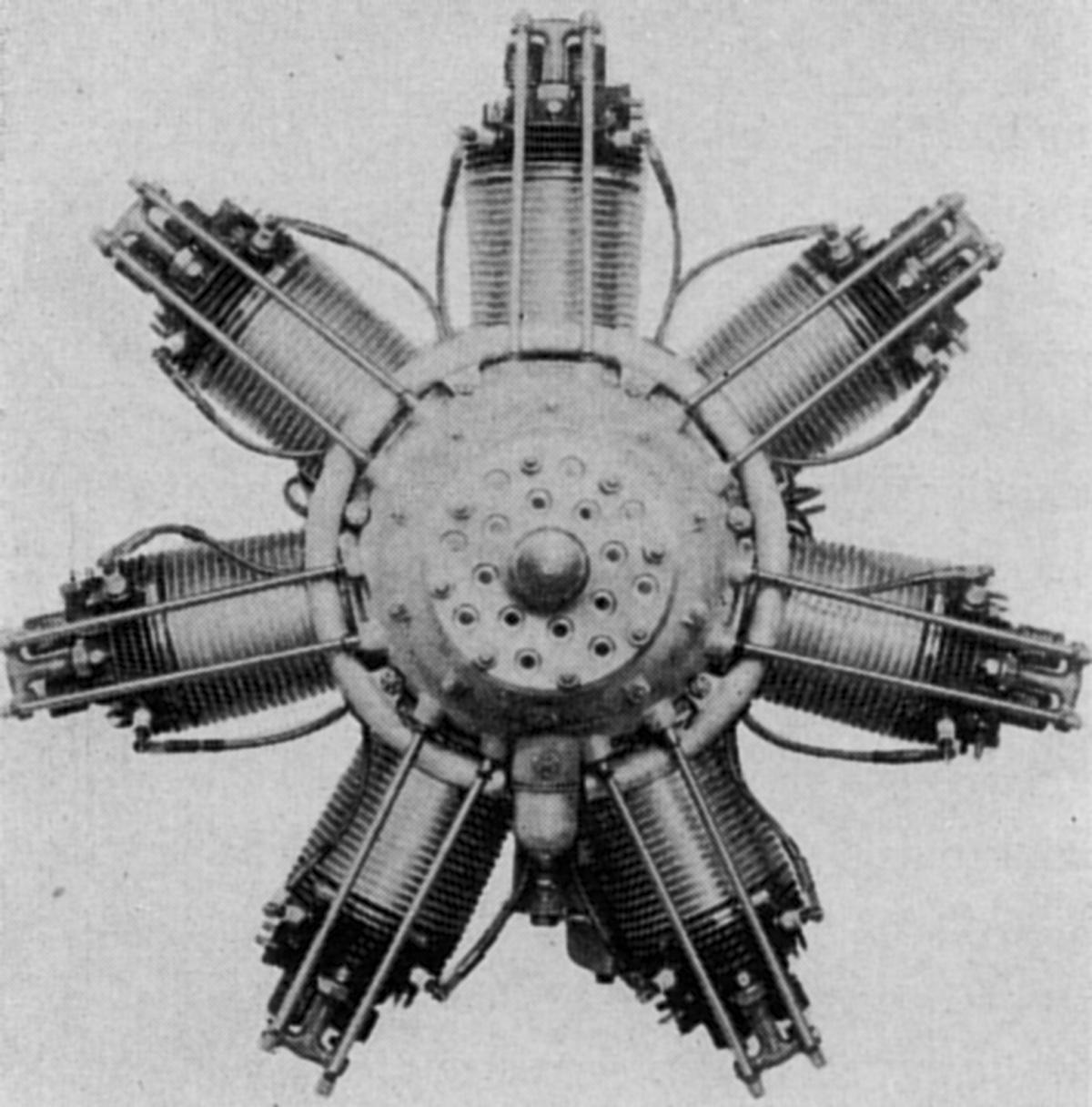
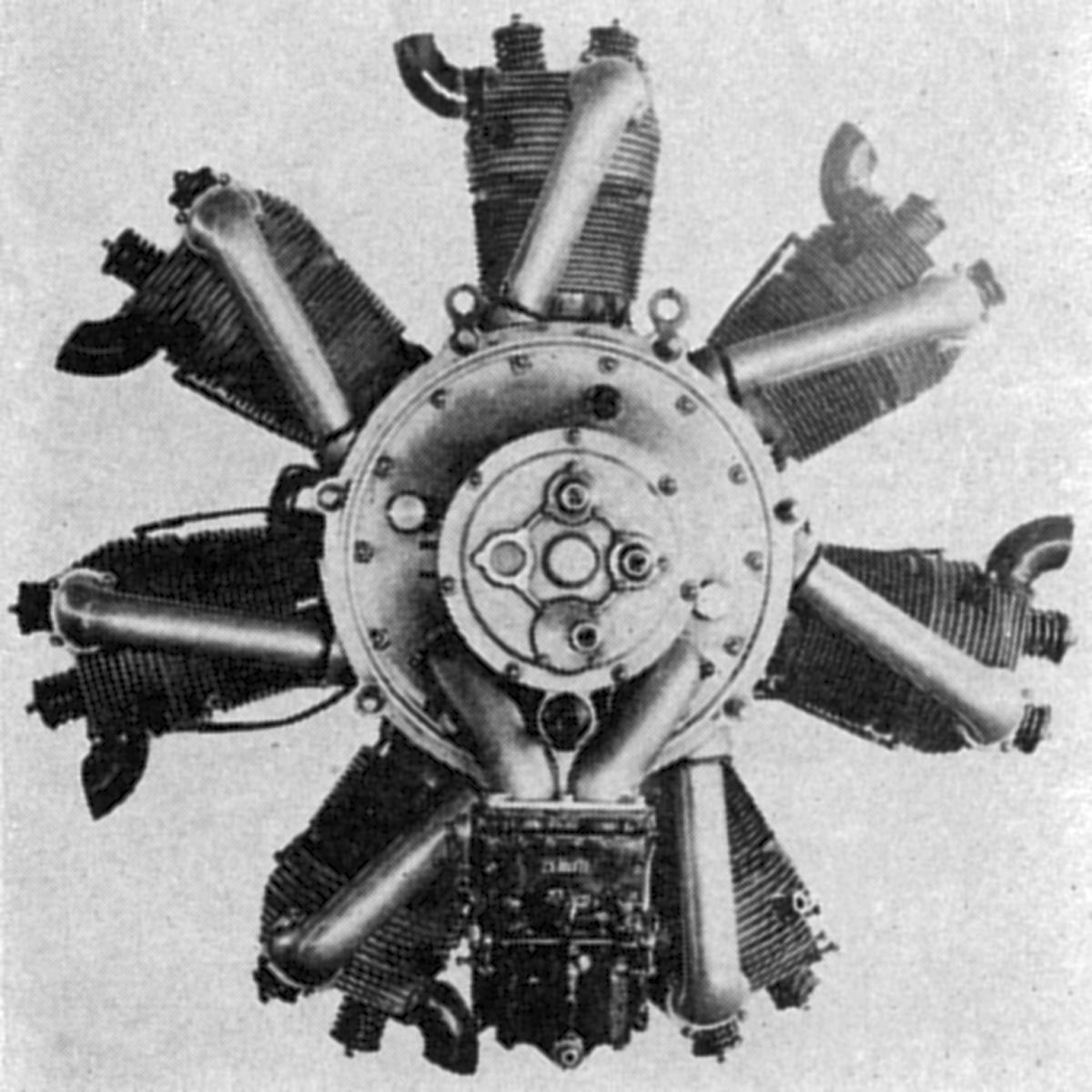
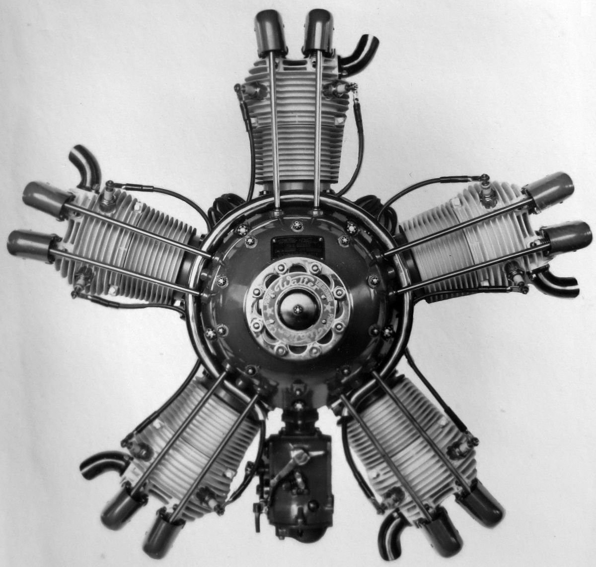
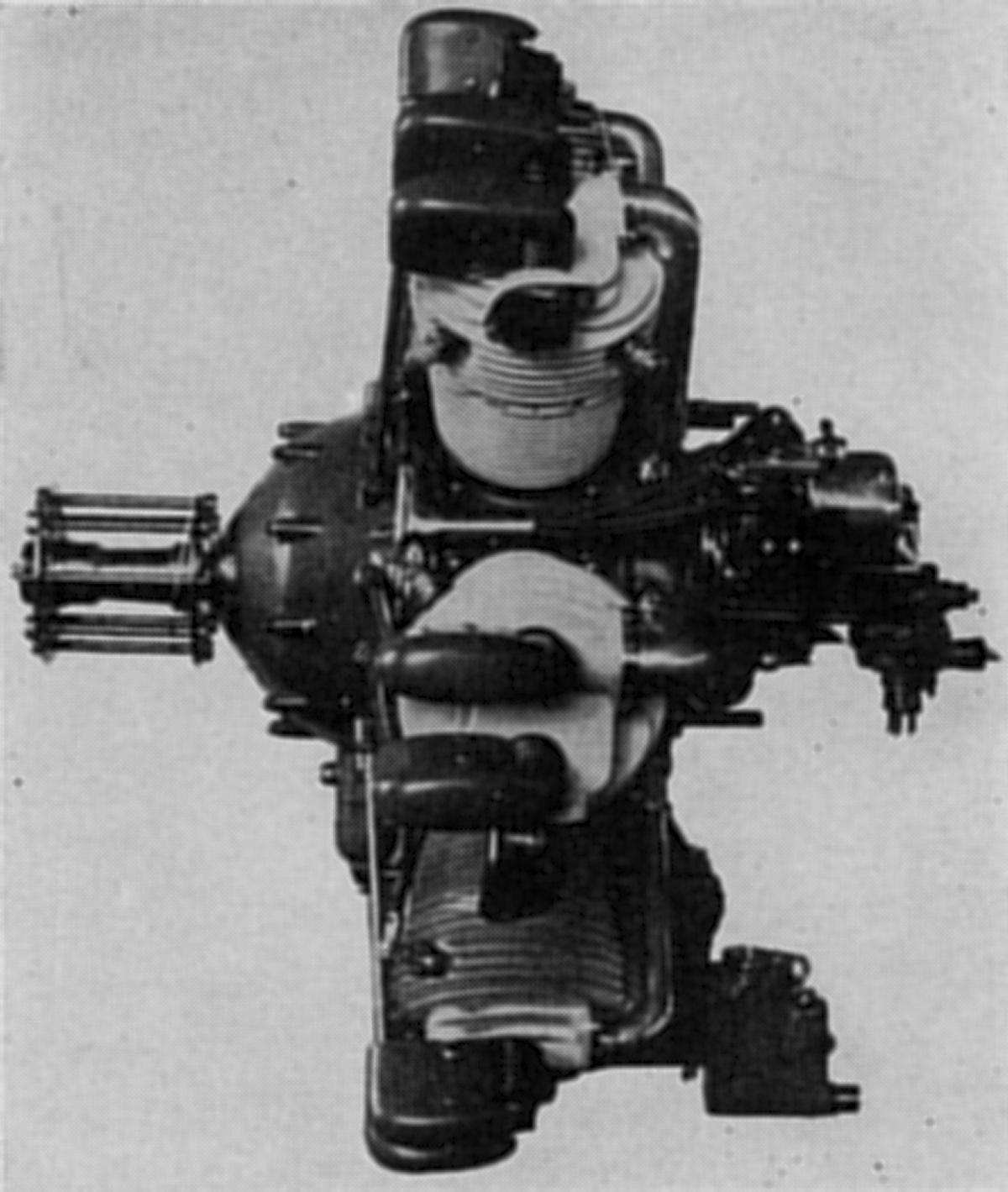
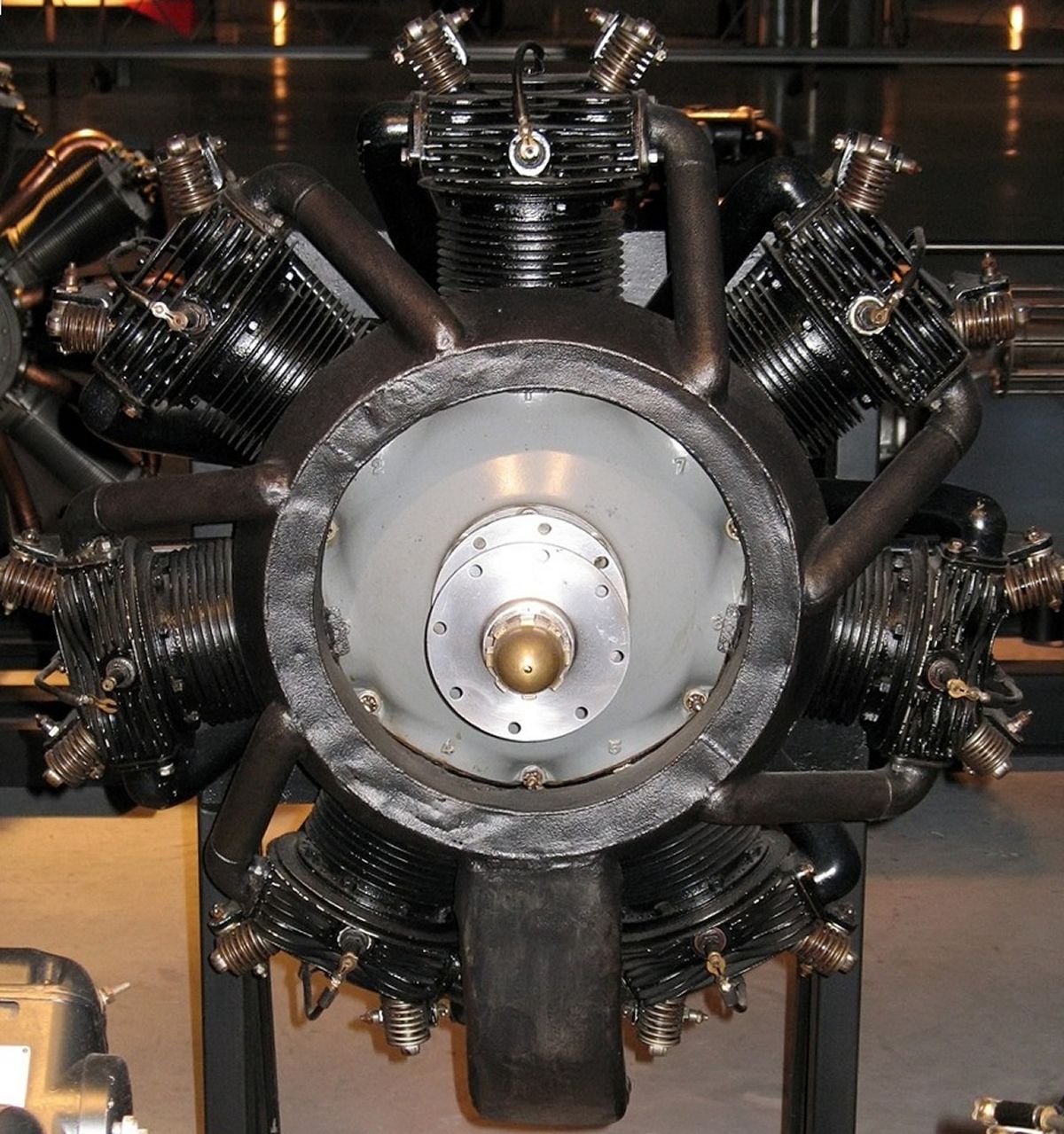
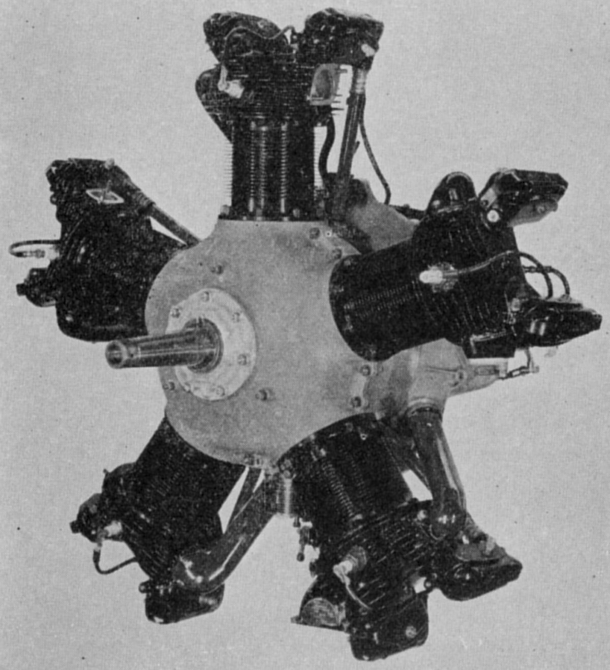
The NZ 85, a radial seven released in 1926 and based on NZ 60 cylinders and other components, displaced 7.274 l (443.86 in³), was rated 85 hp at 1,400 rpm, 90 hp at 1,500 rpm and 95 hp at 1,600 rpm. It weighed 125 kg (282 lb), was 990 mm (39") in diameter and 741 mm (29.2") long. A single-track four-lobed cam ring turning at one-eighth crankshaft speed operated all valves. The NZ 90 and NZ 95 models were tuned and improved NZ 85 versions.
 |
 |
 |
 |
| (Wiki) | (A39) | ||
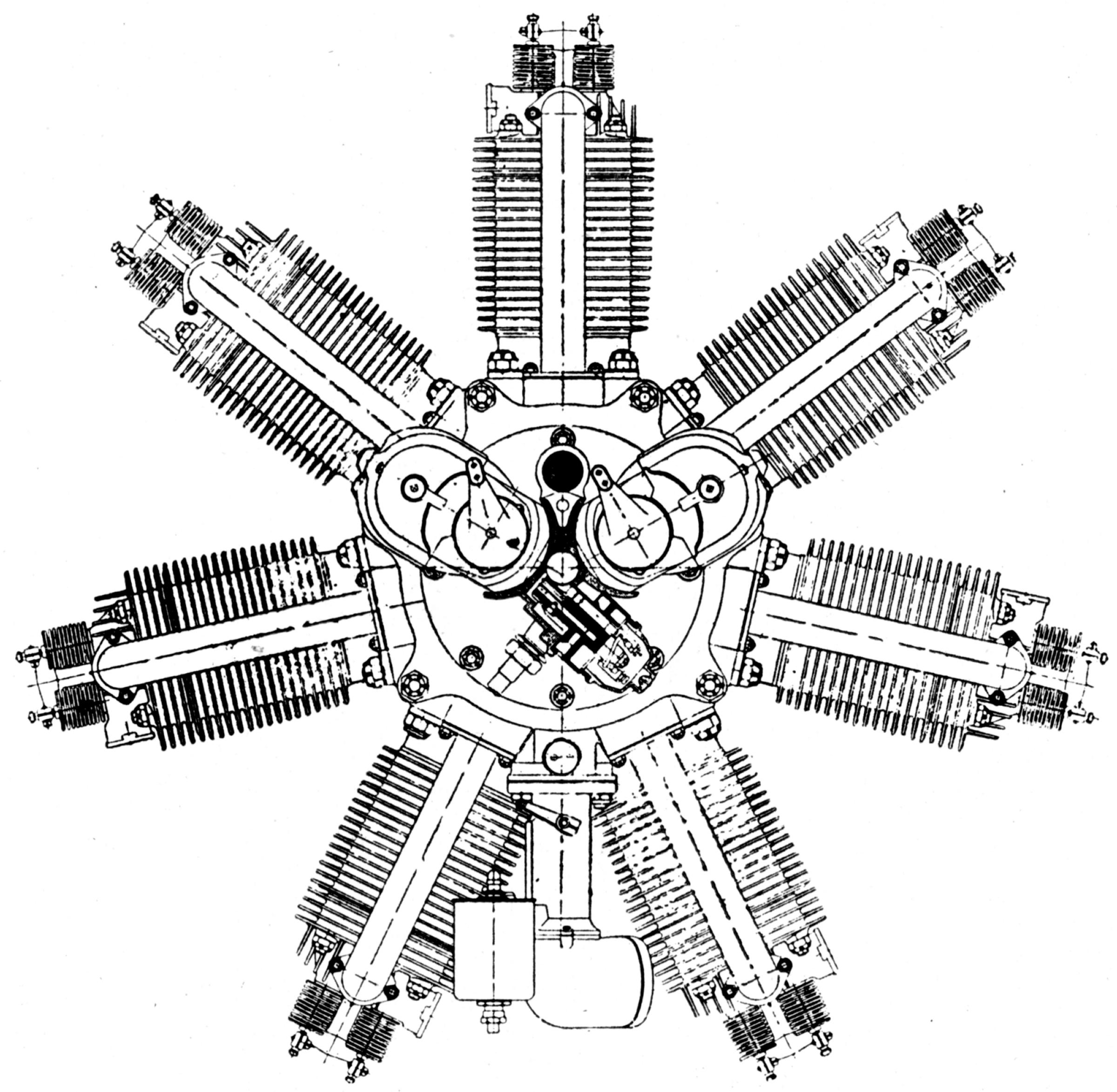
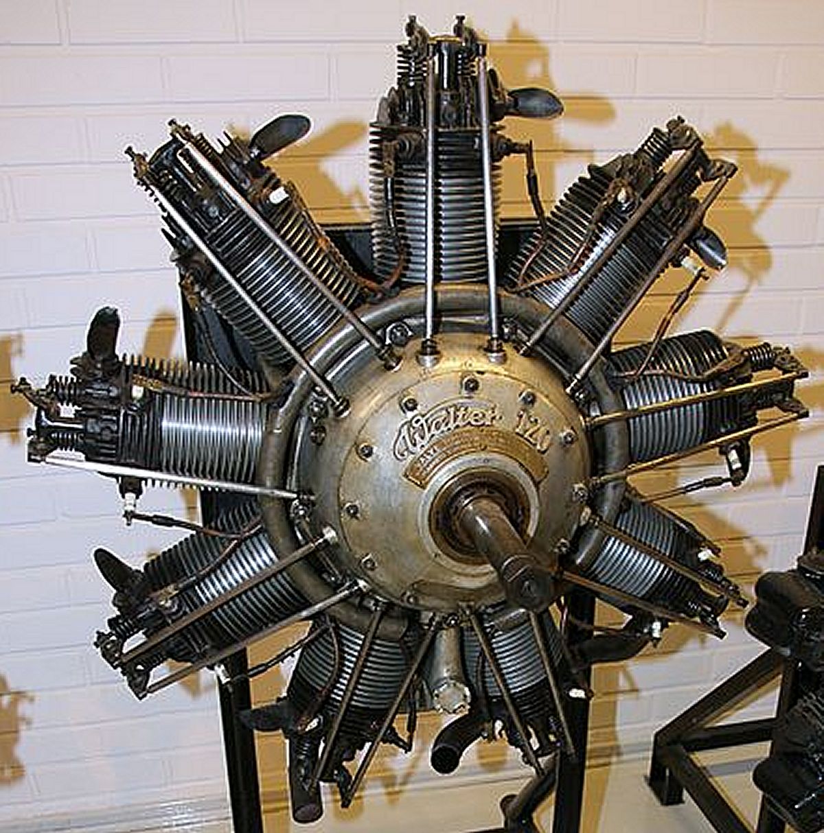
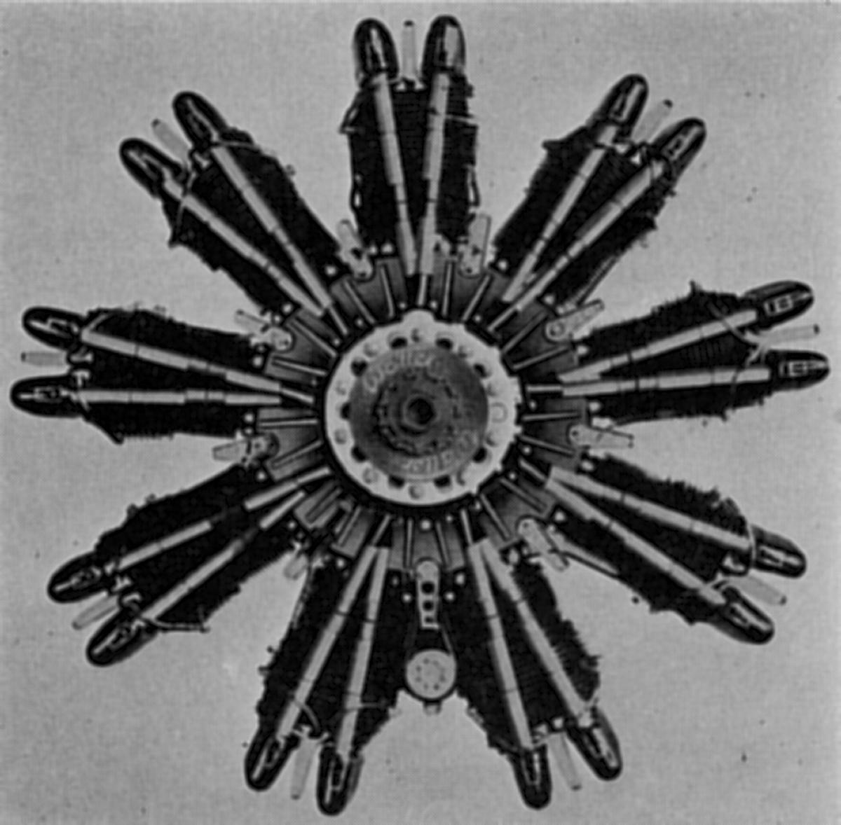
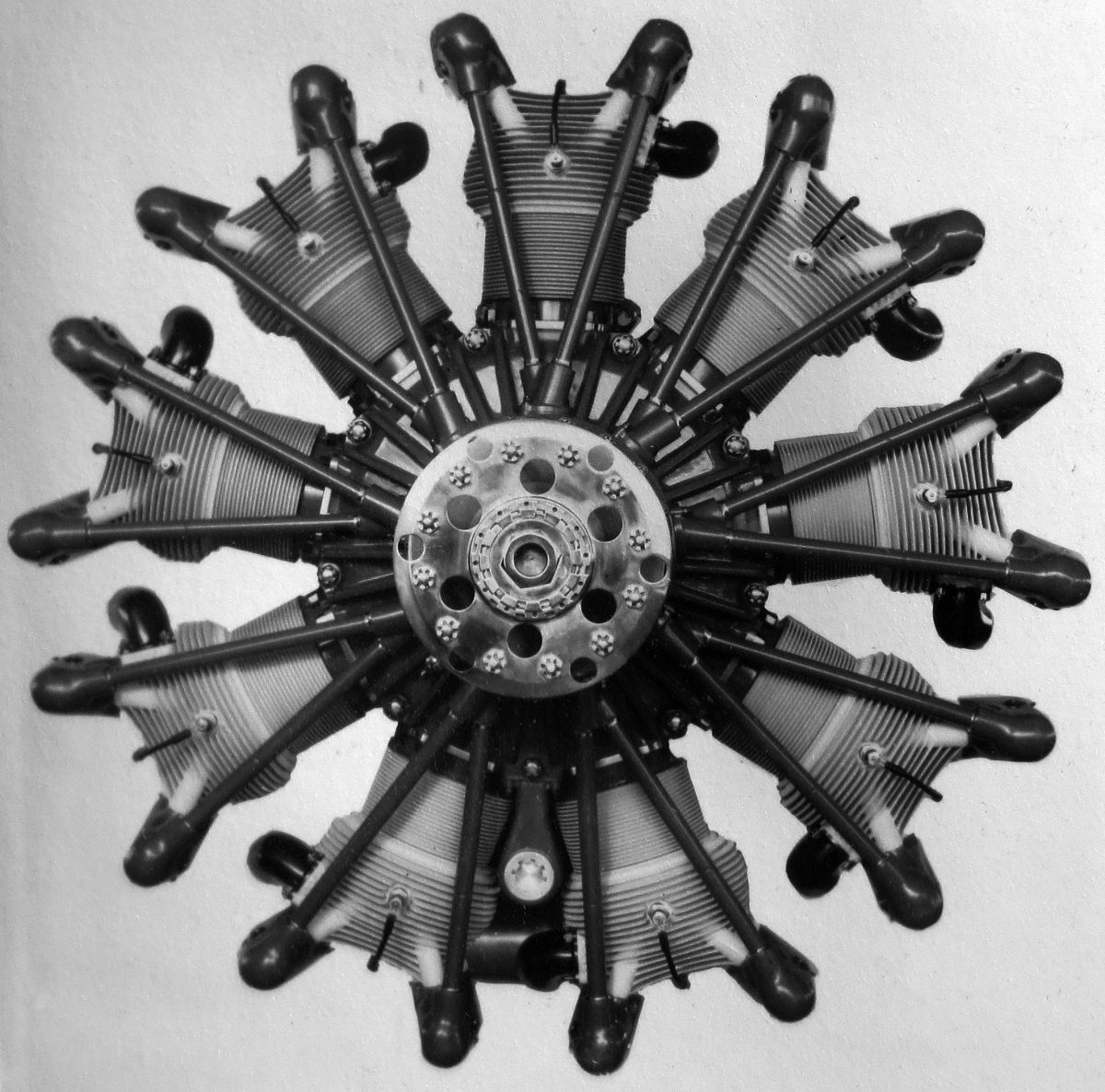
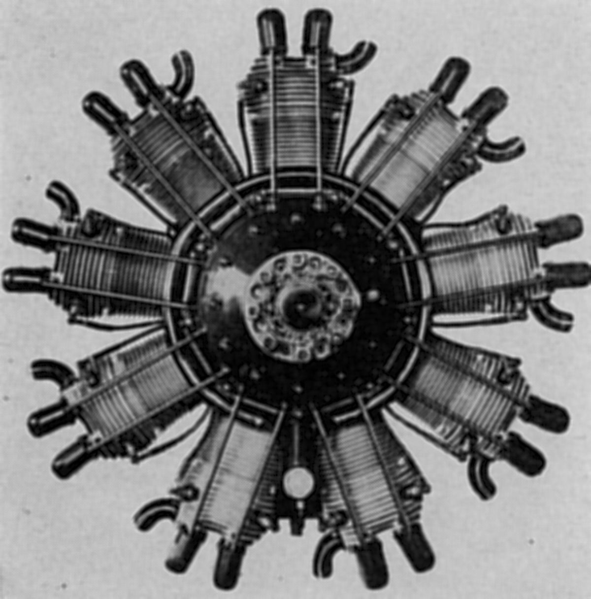
The NZ 120, released in 1922, was a radial nine based on NZ 60 cylinders and other components, displaced 9.352 l (570.68 in³), had a 4.48:1 compression ratio, was rated 120 hp at 1,550 rpm and 135 hp at 1,600 rpm. It weighed 148 kg (326 lb), was 990 mm (39") in diameter and 826 mm (32.5") long. A triple-track cam ring with two lobes per track turned at one-fourth crankshaft speed.
 |
| (Wiki) |
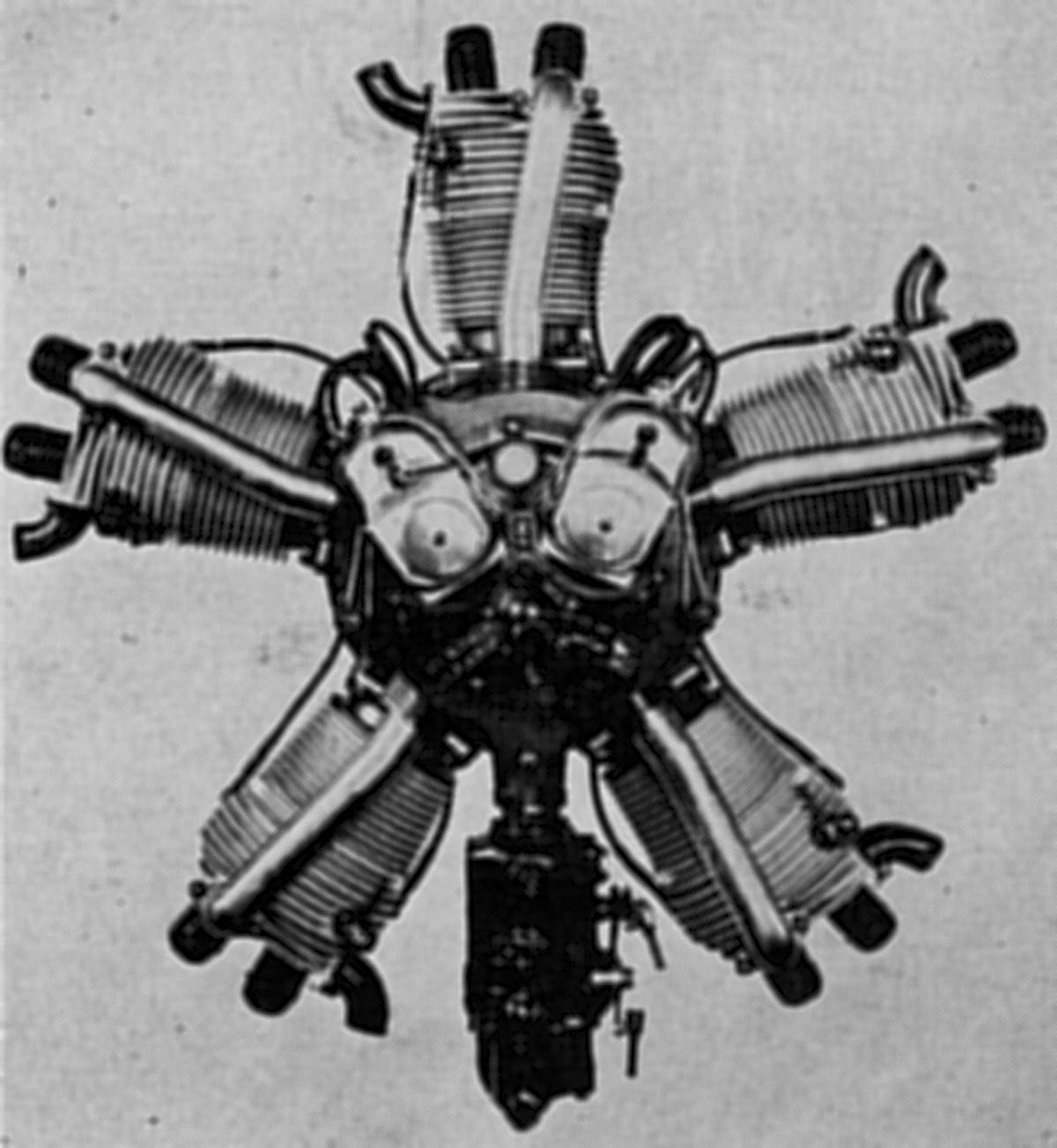
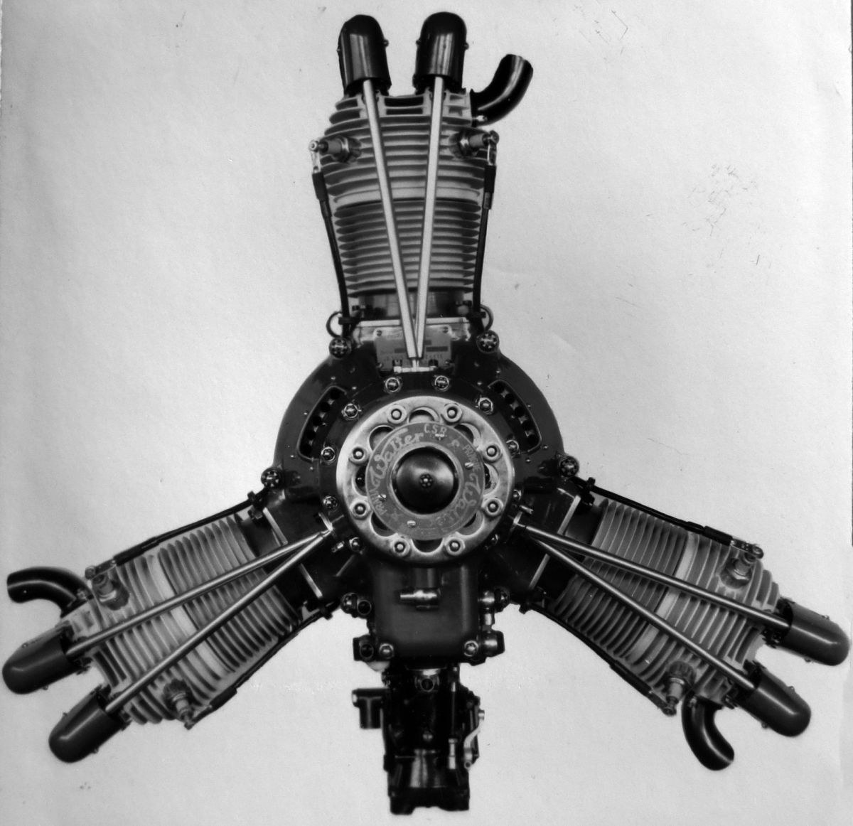
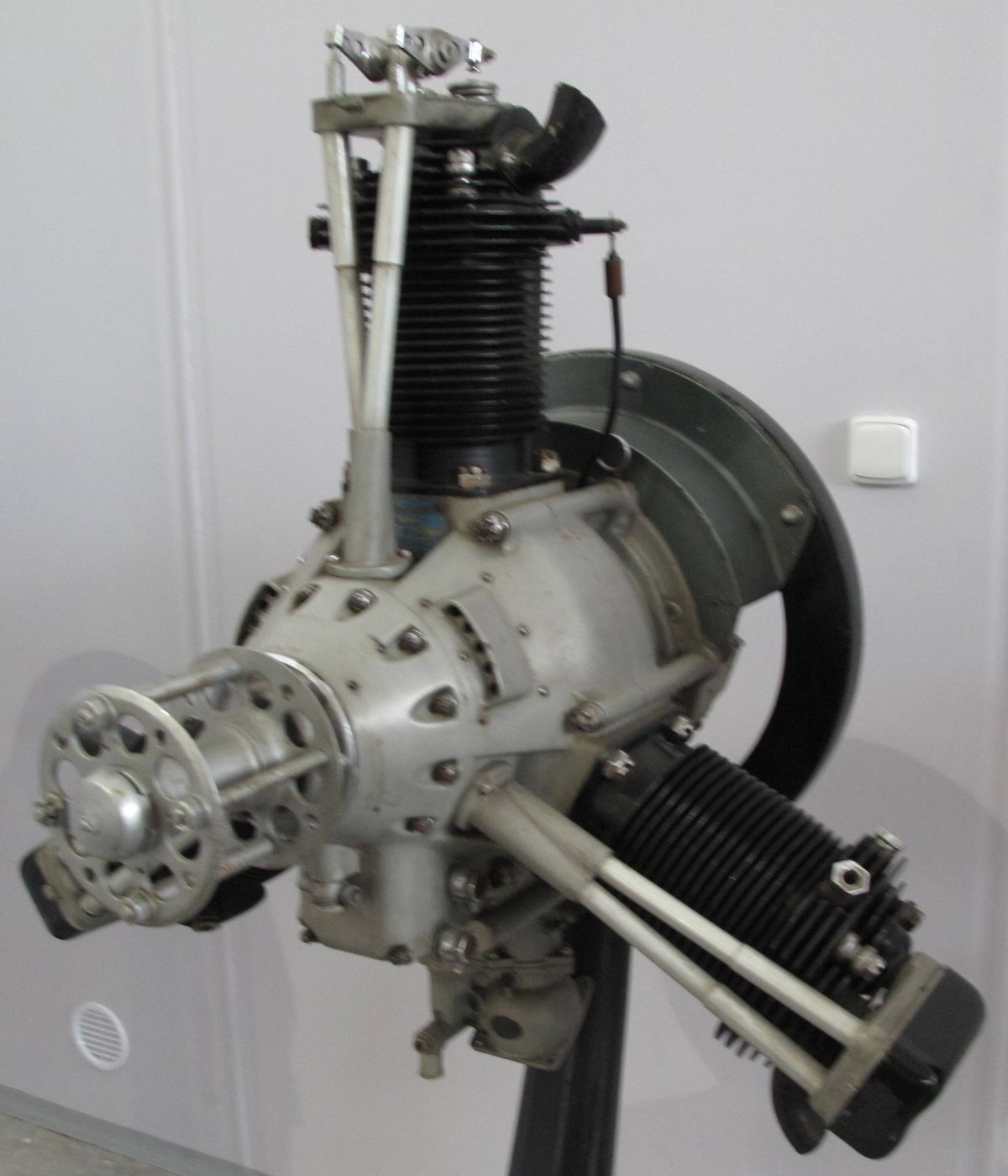
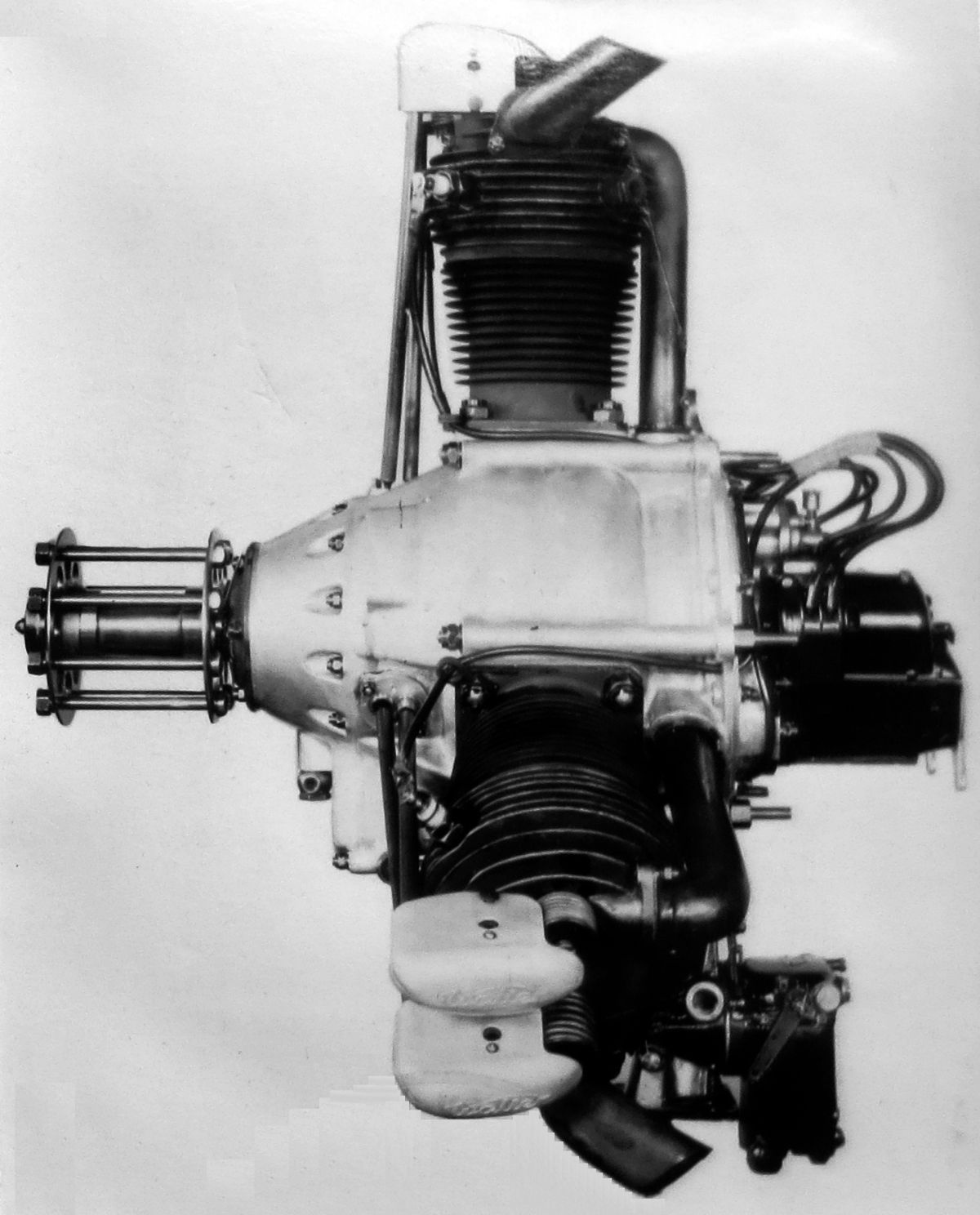
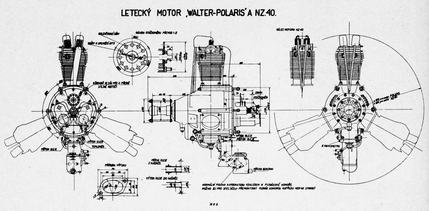
The NZ 40/45, released in 1929, was a radial three based on NZ 60 cylinders and other components, displaced 3.117 l (190.23 in³) and was rated 45 hp at 1,720 rpm and 55 hp at 1,850 rpm. Weight was reported to have been 72 kg (159 lb), diameter was 965 mm (38") and length was 695 mm (27.4"). Vibration problems with the NZ 40 resulted in a redesign, resulting in the NZ 45, which was type-tested in early 1932. Very few NZ 40/45 engines were produced. The line was replaced by the Polaris engine line.
 |
 |
 |
 |
| (Wiki) | (A39) | ||
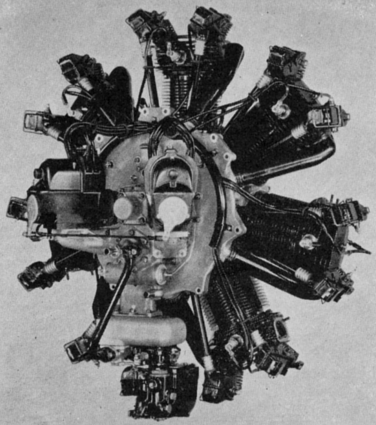
The Castor I, introduced in 1928, was an air-cooled radial seven designed for military and commercial use. With a 135 mm (5.315") bore, 170 mm (6.693") stroke, 17.034 l (1,039.4 in³) displacement 6.0:1 compression ratio, it was rated 240 hp at 1,750 rpm and 260 hp at 1,850 rpm Using a 50% benzol with gasoline, fuel and oil consumptions were 0.484 - 0.506 and 0.044 lb/hp/hr. Weight was 248 kg (547 lb). While the Castor I superficially resembled the NZ models, numerous refinements were incorporated. The cylinder barrels were turned from solid forged steel billets with the cooling fins and the mounting flange integral. The barrel tops were threaded and screw screwed into cast aluminum-alloy heads. Castor heads were not shrunk in place but were locked by a split stirrup that pressed the head bottom against the barrel when tightened. The valves were inclined slightly to the cylinder axis and seated upon bronze rings that were pressed into the cylinder head. The head also carried two bronze valve guides and brackets for the rocker arms that were supported upon roller bearings. These rocker arms and the triple helical concentric valve springs were protected by metal cups. A double-track four-lobe cam ring located at the front of the engine, and turning at one-eighth crankshaft speed operated the rocker arms via push rods. The aluminum-alloy pistons had slightly concave heads and ribs underneath that extended to the piston pin bosses. The piston pins were hollow and fitted with aluminum plugs. Two compression rings and an oil scraper were fitted above the piston pin. The articulated connecting rod system used an H-section master rod and tubular-shank link rods. The master rod big end was supported on the crankpin by two roller bearings. The two-piece crankshaft was ran on three roller bearings and a ball thrust bearing at the front. Two aluminum castings joined at the cylinder plane by long through bolts comprised the main crankcase. The front crankcase section carried the cam mechanism. A bevel gear at the cam idler shaft front end drove a cross shaft whose axis was below and at right angles to the crankshaft; this cross shaft drove two magnetos supported by brackets cast integral with the crankcase nose section. Either Scintilla or Bosch magnetos supplied dual ignition. The rear crankcase wall, in addition to forming a rear main bearing support, also formed the forward wall of the centrifugal induction fan mounted on the crankshaft rear journal extension. The aft casting formed the close-fitting induction fan rear wall along with auxiliary drives. A leather faced oil seal lightly pressed against the bearing housing by a helical spring surrounded the fan boss preventing crankcase oil from entering the induction fan. Tangential pipes led the fuel/air mixture from the induction fan to the cylinder inlet ports. A double Zenith carburetor mounted below and aft supplied mixture to the fan center. A gear pump located in the rear housing and driven by a pair of spur gears from the crankshaft provided pressurized oil to the engine. Scavenge oil that collected in the sump passed through a strainer and was pumped into an external tank after passing through jackets around the carburetor and induction diffuser. Provisions existed for driving a fuel pump, distributor, tachometer and electric generator. A flange for mounting a starter also was incorporated.
 |
| Castor II (A39) |
The Castor II of 1932, an improved Castor version with identical dimensions, was rated 260 hp at 1,800 rpm at sea level, 340 hp at 2,000 rpm at sea level, and 275 hp at 1,800 rpm at 1,000 m (3,280 feet). A 6.0:1 compression ratio resulted in 75 octane fuel being specified. Fuel and oil consumptions were 0.51 - 0.55 and 0.022 - 0.033 lb/hp/hr. Weight was 279 kg (615 lb), diameter was 1,245 mm (49") and length was 1,278 mm (50.3"). This design featured fully enclosed valve gear.
The Castor IIR was a geared Castor II with propeller reduction gears. It was rated 280 hp at 2,060 rpm and 380 hp at 2,300 rpm at sea level, and 305 hp at 2,060 rpm at 1,400 m (4600 feet). Fuel consumption was 0.550 - 0.585 lb/hp/hr. Length was 1,488 mm (58.6") and weight was 296 kg (652 lb).
 |
| Castor III (Wiki) |
The Castor III of 1934 was identical to the Castor II but ran at higher speed. It was rated 320 hp at 2,000 rpm and 430 hp at 2,250 rpm at sea level, and 342 hp at 2,000 rpm at 1,400 m (4,260 feet). Fuel consumption was 0.54 - 0.57 lb/hp/hr.
The Castor IIIR was a geared Castor III rated 320 hp at 2,010 rpm and 420 hp at 2,250 rpm at sea level, and 345 hp at 2,010 rpm at 1,200 m (3,938 feet).
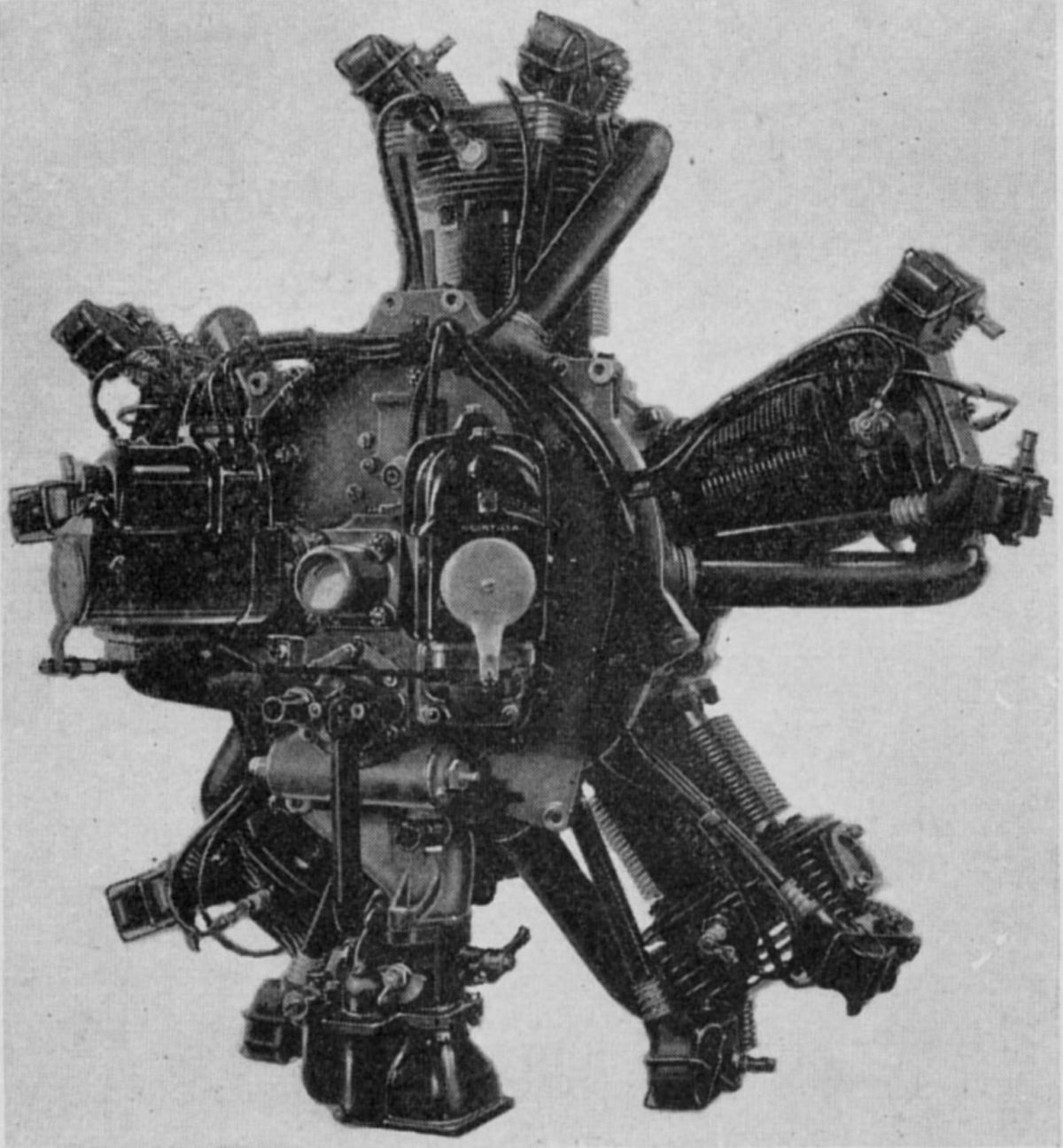
The Pollux I was a 1934 nine-cylinder companion to the Castor I. With a 135 mm (5.315") bore and 170 mm (6.693") stroke, it displaced 21.900 l (1,336.4 in³. It was normally rated 320 hp at 1,800 rpm but produced 350 hp. Weight was 289 kg (638 lb), diameter was 1,253 mm (49.36") and length was 1,220 mm (48.03").
 |
 |
| (A39) | (Wiki) |
The Pollux II was a nine-cylinder companion to the Castor II displacing 21.900 l (1,336.4 in³. It was rated 340 hp at 1,800 rpm and 450 hp at 2,250 rpm at sea level, and 365 hp at 2,070 rpm at 1,200 m (3,938 feet). With a 6.0:1 compression ratio it required 80 octane fuel. Specific fuel and oil consumptions were 0.52 - 0.55 and 0.029 lb/hp/hr. Weight was 323 kg (712 lb), diameter was 1,254 mm (49.4") and length was 1,220 mm (48"). A Stromberg NAR-80 carburetor supplied the mixture and two Scintilla GN-9-DSCN magnetos provided ignition.
The Pollux IIR was a 3:2 planetary-geared Pollux II normally rated 360 hp at 2,070 rpm and 480 hp aIt 2,250 rpm at sea level, and 382 hp at 1,400 m (4,600 feet) using 80 octane fuel. Weight was 341 kg (751 lb) and length was 1,516 mm (59.7").
The direct-drive Pollux III is the same as the Pollux II except the output. Normally rated 420 hp at 2,000 rpm and 560 hp at 2,250 rpm at sea level, and 440 hp at 2,000 rpm at 1,400 m (4,600 feet). Fuel and oil consumptions were 0.54 - 0.57 and 0.022 - 0.033 lb/hp/hr.
The Pollux IIIR corresponded to the Pollux IIR except that it had a sea-level rating of 420 hp at 2,010 rpm and 550 hp at 2,250 rpm, and delivered 440 hp at 2,010 rpm and 1,200 m (3,940 feet).
 |
| Regulus II (Wiki) |
The Regulus II was a 1934 direct-drive radial five using Castor II cylinders. With a 135 mm (5.315") bore, 160 mm (6.299") stroke, 11.451 l (698.79 in³) displacement and 5.8:1 compression ratio, it was sea-level rated 185 hp at 1,800 rpm add 239 hp at 1,950 rpm. Fuel and oil consumptions were 0.506 - 0.55 and 0.022 and 0.033 lb/hp/hr. Weight was 191 kg (421 lb), diameter was 1,185 mm (46.7") and length was 1,104 mm (43.46"). One Zenith 50-DCJ double carburetor was fitted.
The Regulus III was identical to the Regulus II except for a higher speed. It was rated 210 hp at 2,100 rpm and 270 hp at 2,300 rpm at sea level. Fuel consumption was 0.528 - 0.572 lb/hp/hr.
 |
| Atlas I (Wiki) |
The Atlas I was a 1930 air-cooled radial nine with a 165 mm (6.496") 180 mm (7.087"), 34.640 l (2,113.89 in³) and 5.3:1 compression ratio rated 600 hp at 1,900 rpm and 650 hp at 1,950 rpm. Weight was 480 kg ( 1,058 lb), diameter was 1,470 mm (57.87") and length was 1,460 mm (57.48"). Compressed air was used for starting.
The Atlas IR was a 13:8-geared Atlas I that produced 709 hp at 1,950 rpm and weighed 540 kg (1,190 lb).
 |
 |
| (Wiki) | (A39) |
The Vega was a 1929 air-cooled radial five, a later and refined NZ 60 designed by František Adolf Barvitius. Castor engine cylinders with barrels turned from solid steel forgings with integral cooling fins, and cast aluminum alloy heads that were screwed onto the cold barrel. The joint was made tight by clamping a steel split stirrup around the lower head. Although the bore and stroke remained 105 mm (4.134") and 120 mm (4.724"), the displacement at 5.195 l (317.04 in³), and the compression ration was 5.15:1, the rated output was raised to 85 hp at 1,750 rpm, and 90 hp at 1,800 rpm. Weight was 102.5 kg (226 lb). Fuel and oil consumptions were 0.50 and 0.033 lb/hp/hr. The Vega was equipped with a Zenith 50J carburetor and two Scintilla magnetos.
 |
 |
| (Wiki) | (A39) |
The Venus was a 1929 radial seven corresponding to the NZ 85, except that the cylinders were like those used in the Vega design, each with a 5.15:1 compression ration and displacing 1.039 l (63.41 in³) for a total of 26.393 l (1,610.58 in³). The Venus was normally rated 110 hp at 1,750 rpm and 115 hp at 1,800 rpm. Weight was 178 kg (393 lb). Fuel and oil consumptions were 0.50 and 0.033 lb/hp/hr. Two Scintilla magnetos provided dual ignition, and the mixture was furnished by a Zenith 50J carburetor.
 |
| Mars (A39) |
The Mars was a 1929 air-cooled radial nine corresponding to the NZ 120. With a 105 mm (4.134") bore, 120 mm (4.724") stroke, 9.352 l (570.68 in³) displacement and 5.15:1 compression ratio, it produced a normal 145 hp at 1,750 rpm and 150 hp at 1,800 rpm. Fuel and oil consumptions were 0.50 and 0.033 lb/hp/hr. Weight was 159 kg (351 lb). Two Scintilla magnetos furnished dual ignition, and the mixture was supplied by a Zenith 42 DCI carburetor.
 |
 |
 |
 |
| (Wiki) | (Wiki) | (Wiki) | (Wiki) |
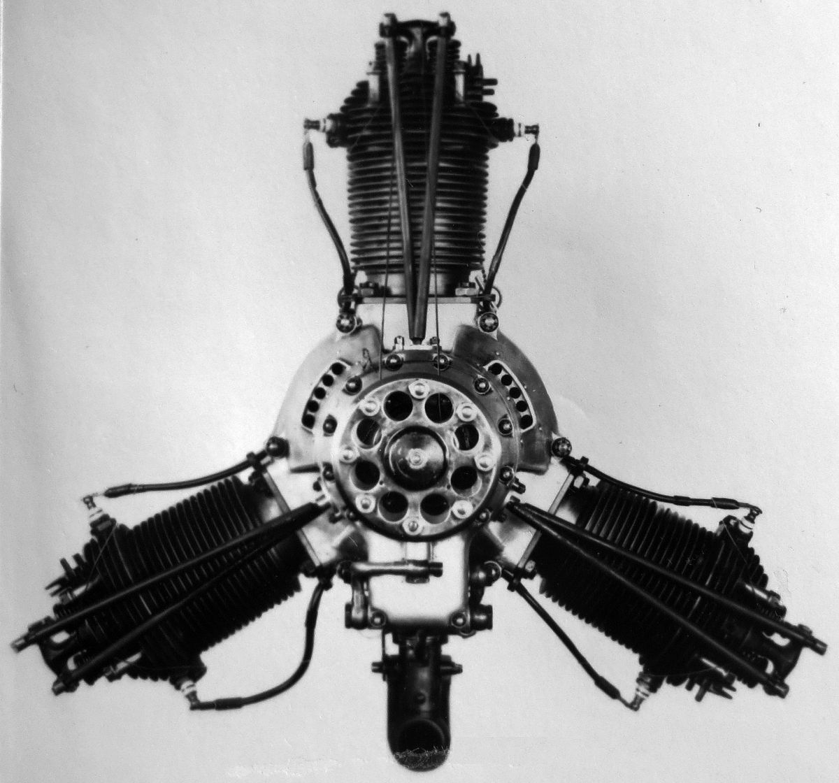
The Polaris I was a 1932 air-cooled radial three similar to the NZ40, except that Vega cylinders were used and the compression ratio was raised to 5.3:1. Normal output was 50 hp at 1,800 rpm. Maximum output was 60 hp at 2,000 rpm. Weight and overall dimensions were the same as the NZ 40.
The Polaris II was a refined Polaris I introduced in 1934 with a 6.0:1 compression ratio. It was rated 70 hp at 2,330 rpm. Fuel and oil consumptions were 0.53 - 0.59 land 0.022 lb/hp/hr. Polaris engines employed heat-treated pistons of R.R. 53 alloy and three rings. The master connecting rod had a pressed-in liner for the big end for use with a floating babbitted bushing. Two roller bearings and one ball bearing for the propeller thrust supported the two-piece crankshaft. The aluminum-alloy crankcase was split in the cylinder plane with two bolts between adjacent cylinders holding the two sections together. The front and rear covers were also aluminum alloy. Completely enclosed valve gear included a two-row cam located at the engine front. Either Zenith or Stromberg carburetors provided a mixture which first entered a chamber in the crankcase rear. Dry-sump lubrication employed a two-gear pump, and two Scintilla PN3-DF magnetos provided ignition.
Warner
Originally chartered as Aeronautical Industries Incorporated, the Warner Aircraft Corporation of Detroit, Michigan, whose new name originated in 1927, built radial air-cooled engines that were similar in design and had many interchangeable parts. The cylinders consisted of a forged chrome molybdenum steel barrel with a bolted-on Bohn aluminum alloy head having horizontal cooling fins. Two tulip-shaped valves, inclined at a 45° angle, were operated by push rods and rocker arms. Aluminum bronze valve seats were shrunk into the head. The valves had a 1.500" (38.1 mm) clear diameter and 0.406" (10.31 mm) lift. The intake valve was made of tungsten steel and the exhaust valve from a cobalt alloy. Eight bolts attached the cylinder head to the barrel and another eight the barrel to the crankcase. In the earlier designs, only the rocker arm aft halves and push rods were enclosed. The exhaust and inlet ports were diametrically opposite, facing at right angles to the crankshaft axis. Permanent-mould flat-head Bohnalite pistons were fitted with two compression rings and one oil scraper ring. Articulated connecting rods were used with the master rod having a split big end held together by four bolts, and a directly-applied white-metal-lined bearing. The wrist pins were locked in the link rods and were supported in bronze bearings pressed into the master rod big end side flanges. The crankshaft was machined from a single steel forging and mounted upon three ball bearings, the forward of which carried propeller thrust loads. The crankshaft front was machined to a SAE No. 1 taper. The aluminum crankcase was made in two sections that were joined in the cylinder plane. Two aft-mounted cam rings each had four lobes and ran at 1/8 crankshaft speed. A gearcase was bolted to the induction housing rear and carried the magnetos, an oil pump, oil strainer, and pressure relief valve. Starter mounting provisions also existed. The magnetos were driven by bevel gears at a 33° angle to the crankshaft, creating maintenance access and space for a starter. The induction system consisted of an annular passage cored in an aluminum casting. A Stromberg NAS-5A carburetor was attached to the passage lower extremity and intake pipes led to each cylinder. This casting also served as an engine support. The dry-sump lubricating system used gear pressure and scavenging pumps.
 |
 |
 |
| (Wiki) | (A39) | (A39) |
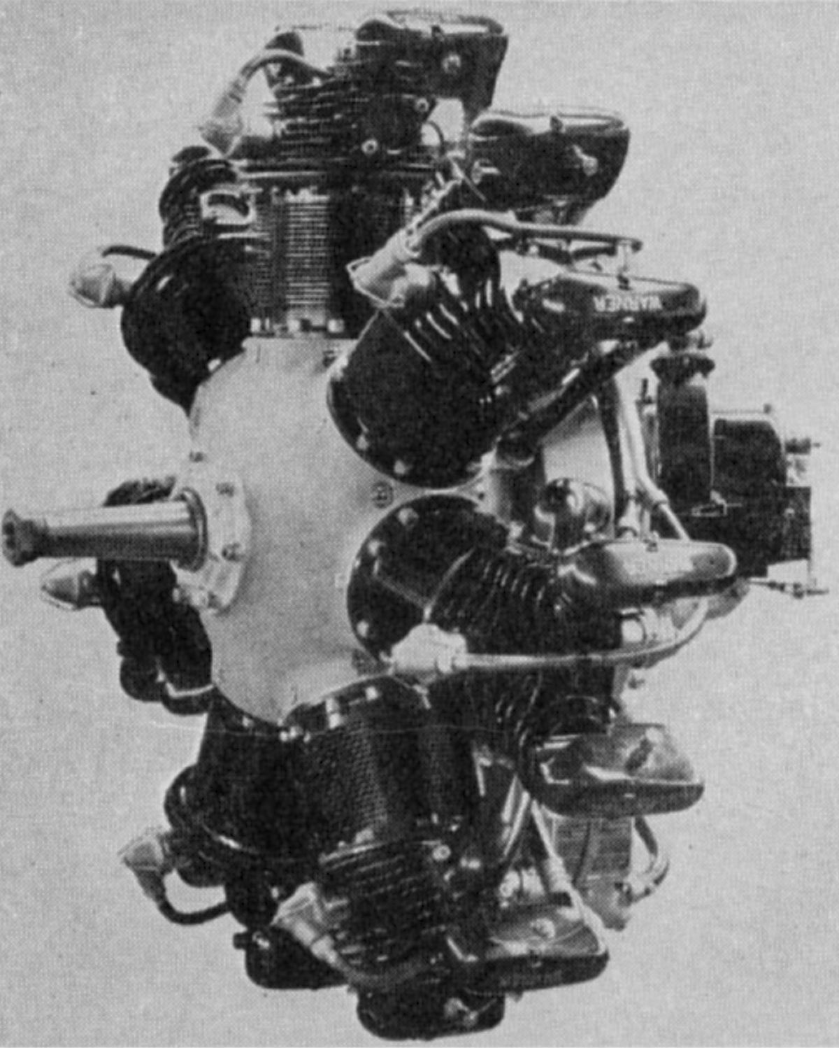
The Scarab (military R-420), which first ran in November 1927, was a radial seven with a 4.250" (107.95 mm) bore and stroke displacing 422.04 in³ (6.916 l). With a 5.15:1 compression ratio, engine numbers 10, 15, 17, 18, 32, 34, 46 and 58 were rated 110 hp at 1,850 rpm until their crankshafts were replaced by Department of Commerce Approved Type Certificate No. 2, issued on 2 Apr 1928. Early Scarabs could produce 122 hp at 1,950 rpm. Fuel and oil consumptions were 0.55 and 0.025 lb/hp/hr. Two Scintilla MN-7D magnetos supplied dual ignition. Inlet valves opened 10° early and closed 60° late; exhaust valves opened 60° early and closed 10° late, with the tappets set at a 0.027" clearance. Early engine dry weight, without propeller hub or starter, was 275 lb (125 kg). Diameter of the 1928 series was 35.5" (902 mm); the 1929 series diameter was 36.25" (921 MM). Length without starter was 29" (737 mm). The improved Series 30 engines were rated 125 hp at 2,050 rpm. Approved Type Certificate No. 2, which was again revised on 28 Aug 1933 to include the Scarab Series 40, as well as the 28, 29 and 30 Series engines. With the compression ratio now at 5.2:1 the minimum recommended fuel rating was 67 octane. Series 40 engines had improved cylinder heads and fully enclosed valve gear. Engine Specification dated 13 Mar 1939 approved Scintilla MN-7D magnetos as before, along with Bosch or Autolite battery ignition. Dry weight with magnetos was 292 lb (132 kg), and with battery ignition the weight was 295 lb (134 kg). Scarab production continued 1944 with a total of 848 Models 28, 29, 30, 40 and 50 being built.
 |
 |
| (A39) | (A39) |
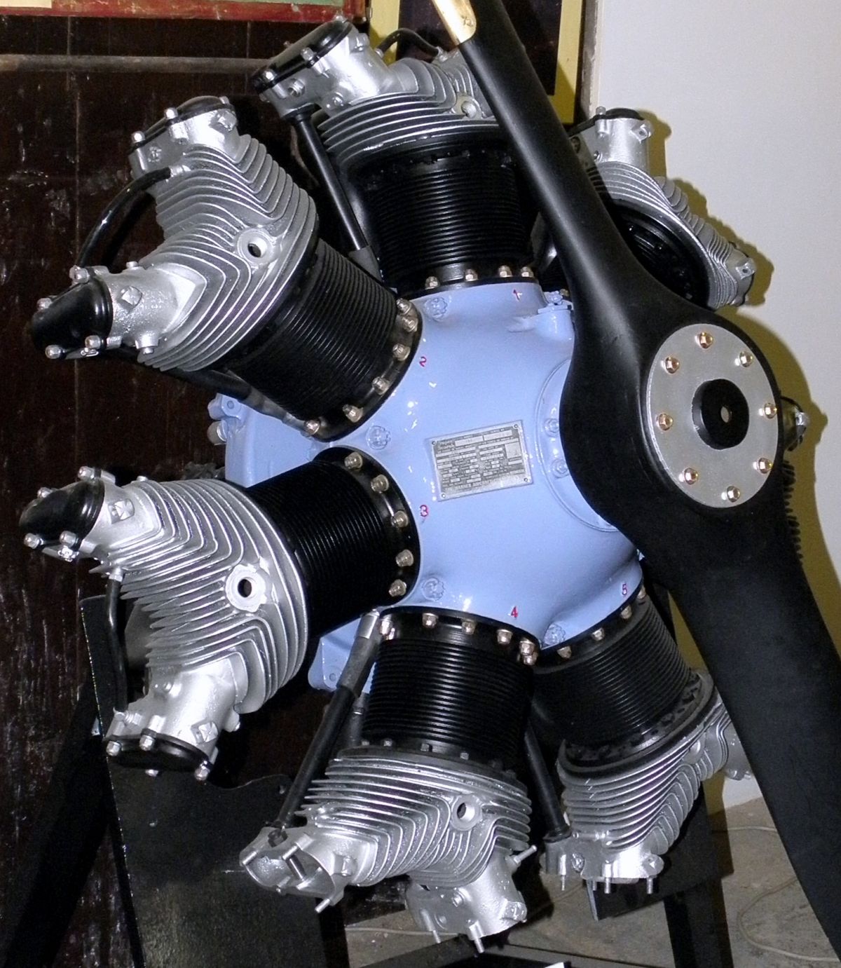
The Scarab Junior, first run in November 1930, was a radial five using Scarab cylinders. With a 301.46 in³ (4.940 l) displacement and 5.2:1 compression ratio, it was rated 90 hp at 2,025 rpm and received Department of Commerce Approved Type Certificate No. 54 on 21 Jun 1930. Rated-power fuel and oil consumptions were 0.55 and 0.02 lb/hp/hr. The originally specified dry weight (without propeller hub or starter) was 230 lb (104 kg), but the Engine Specification dated 13 Mar 1939 gave 237 lb (107.5 kg) less generator, starter and exhaust stacks. Diameter was 36.5" (927 mm) and length (minus starter) was 29" (737 mm). The mounting ring circle was 17" (432 mm) in diameter. The mixture was supplied by a Holley 429 carburetor with 1.4375" venturi, and Scintilla PN5-D, SB5R or Bosch JFS-ARS-20 magnetos supplied dual ignition. Scarab Junior production ceased in 1939 after 93 had been built.
 |
| (A39) |
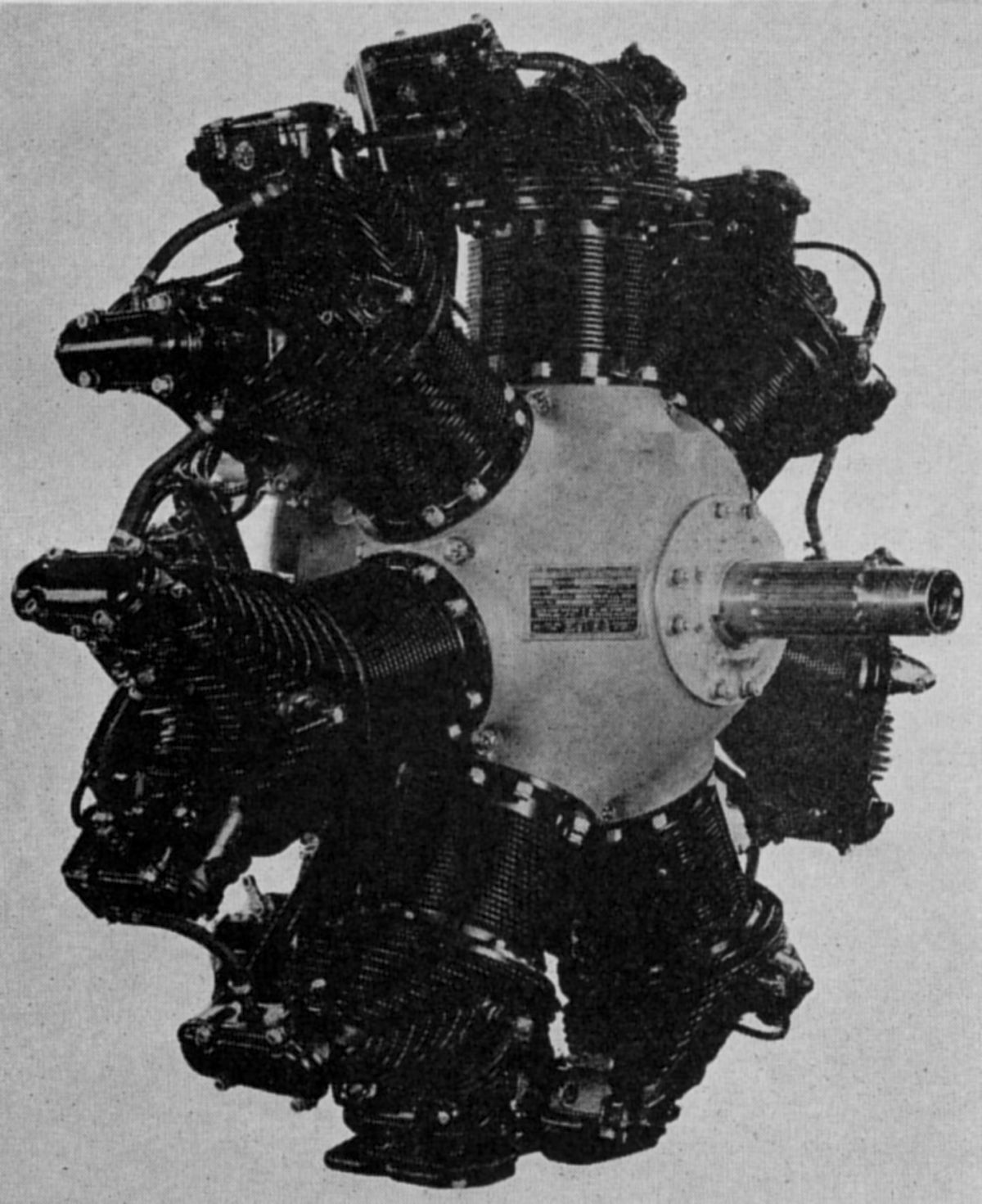
The Super Scarab (military R-500), released in 1932, was an air-cooled radial seven, an enlarged edition of the original Scarab with numerous detailed refinements such as closed rocker boxes and improved cylinder head finning. With a 4.625" (117.48 mm) bore, 4.250" (107.95 mm ) stroke, 499.80 in³ (8.190 l) displacement and 5.2:1 compression ratio, it was rated 145 hp at 2,050 rpm. Dry weight (minus propeller hub and starter) was 305 lb (138 kg), diameter was 36.75" (933 mm) and length was 28.97" (736 mm). Department of Commerce Approved Type Certificate No. 104 was issued on 25 Aug 1933 and specified 73 octane fuel minimum. A 25 Mar 1936 revision covered the Super Scarab Series 50, and included Series 40 with no change in rated performance. The Engine Specification dated 13 Mar 1939 allowed the use of Scintilla MN-7D magnetos and either Bosch or Autolite battery ignition. Dry weight with magnetos was 306 lb (139 kg), and with battery ignition was 310 lb (141 kg). Super Scarab 40, 50 and 50A production ceased in 1945 after 971 had been built.
 |
 |
 |
| (Wiki) | (A39) | (A39) |
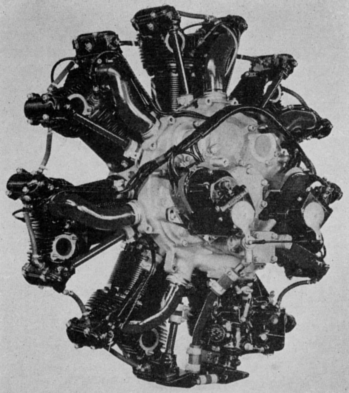
The Super Scarab 165 (military R-500), which appeared in 1939 with a new cylinder head design, compression ratio increased to 6.4:1, plus other detailed improvements, normally delivered 165 hp at 2,100 rpm and 175 hp at 2,250 rpm for take-off. These outputs were approved by the Civil Aeronautics Authority Approved Type Certificate No. 214 that was granted on 9 May 1939. Fuel and oil consumptions were 0.58 and 0.025 lb/hp/hr. Dry weight (without propeller hub or starter) was 333 lb (151 kg), diameter was 37.25" (946 mm) and length (without starter) was 30.39" (772 mm). Scintilla Model MN7-DF magnetos with full manual advance of 30° and Champion M-4 spark plugs furnished dual ignition. A Stromberg NAR-5A carburetor with a 1.9375" venturi supplied the mixture. Inlet valves opened 10° early and closed 60° late; exhausts opened 60° early and closed 10° late. The new cylinder head had pompadour finning and added cooling surface, permitting the use of better cylinder head baffling. The new induction housing had an annular passage without restrictions, which, together with intake pipes of better sweep, resulted in higher volumetric efficiency. Both inlet and exhaust ports faced aft. The overhead valve gear had automatic lubrication. A pressure line led to the No. 1 cylinder; from there oil flowed to the remaining rocker boxes by gravity. A housing cover on the lower rocker box acted as an oil sump, from where a scavenge pump returned the accumulated oil to the supply tank. Provisions existed for installation of a controllable-pitch propeller. An enlarged crankshaft with an SAE No. 20 spline was used. Standard drives were provided for generator, fuel pump, starter, and two additional accessory drives. A carburetor air thermometer and manifold pressure gauge were accommodated.
Super Scarab 165-A was an engine with special accessory drives, and Super Scarab 165-B provided a valve for controllable-pitch propeller installation. The Super Scarab 165-AB featured both. These models were included in Approved Type Certificate No. 214. Production ceased in 1945 after 1,475 had been built.
The Super Scarab 185, which appeared in 1942, featured yet another bore increase to 4.875” (123.83 mm) for a 555.30 in³ (9.100 l) displacement. It was rated 185 hp at 2,175 rpm and 200 hp at 2,475 for five minutes. Compression ratio was 6.2:1. Weight was 344 lb (156 kg). Only 185 Super Scarab 185 engines were produced under Approved Type Certificate No. 235.
No Warner engines were built after 1945. By 7 Sep 1950, all Warner production certificates had expired. The Clinton Machine Company took over in 1950. Warner engines powered numerous golden-age aircraft. Sadly, as these historic aircraft fell into disrepair, the engines, engine mounts and propellers were often scavenged to power WWI replicas that became popular in the 1980s and 1990s. It is not uncommon to find a classic aircraft, sans engine, in storage, and too expensive to restore.
The Warner type certificates live on, owned by the Warner Engine Company LLC of Palmer Lake, Colorado. Although Warner Engine Company is not currently manufacturing new engines, it is a great source of technical information and some parts.
Warner References
Angle, Glenn D, ed. Aerosphere 1939 (New York, New York: Aircraft Publications, 1940).
Pagé, Major Victor W. Modern Aviation Engines (New York: Norman W. Henley Publishing Company, 1929) 1023 – 1027.
Warner Engine Company LLC Website.
Wells-Adams
 |
| Wells-Adams 135 hp (AEE) |
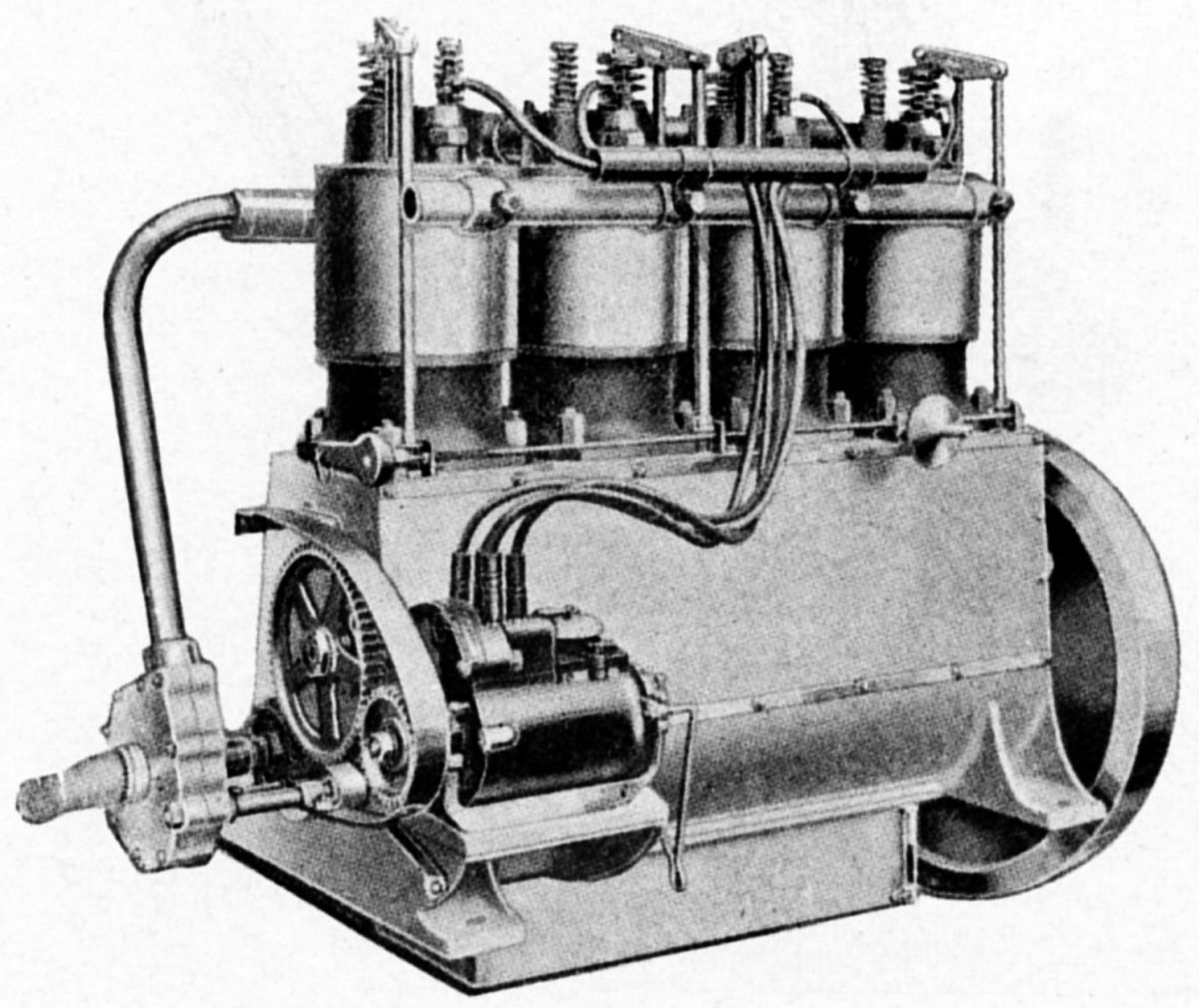
The Wells & Adams Company of Bath, New York, built a water-cooled vertical four that produced 50 hp as early as 1912. Weighing about 200 lb (91 kg), it featured single cylinders with brass jackets, a water pump, an oil pump, mechanically-operated overhead valves, dual high-tension ignition and no valve cages. The chrome-nickel crankshaft operated on five plain main bearings. (Jane’s 1913)
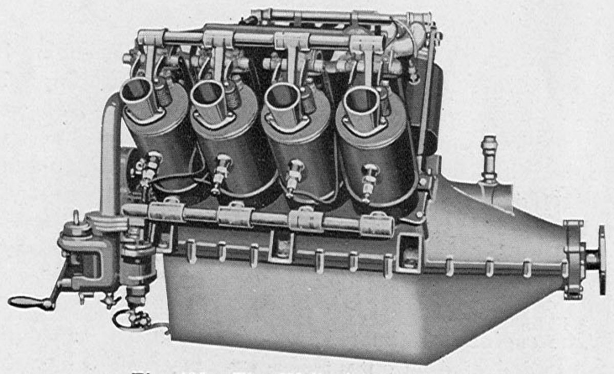
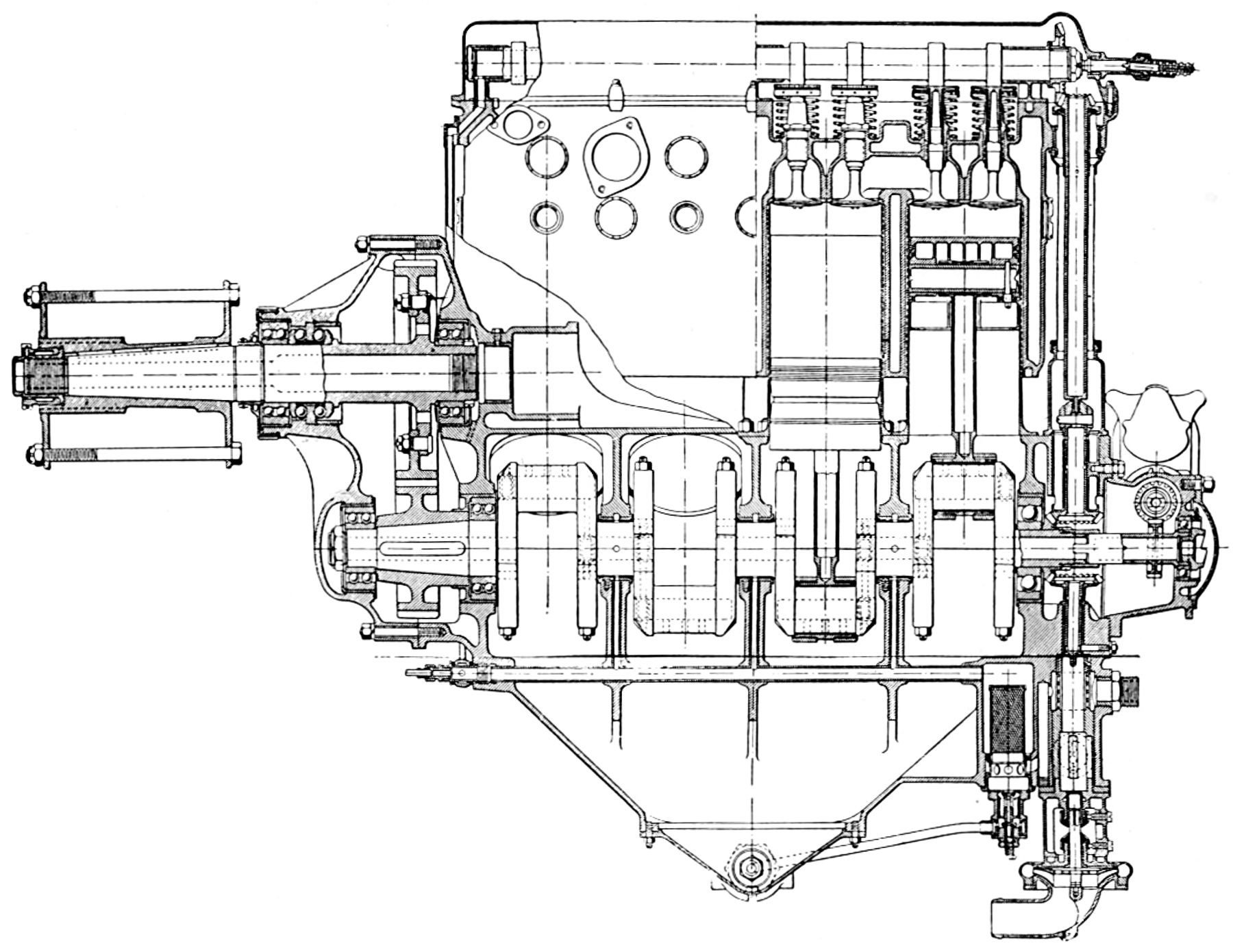
A later water-cooled 90° V-8, with a 4.500" (114.3 mm) bore, 6.000" (152.4 mm) stroke and 763.41 in³ (12.510 l) displacement was rated 135 hp at 1,350 rpm. Weight was about 400 lb (181 kg). The individual cylinders were fitted with nickel-plated spun-brass water jackets. The water outlet, valve rocker-arm bracket, and inlet manifold connection for each cylinder was cast integrally from aluminum. The overhead valves were operated by push rods from a central camshaft in the vee. The connecting rods had tubular shanks and Bosch magneto furnished dual ignition.
Werner & Pfleiderer
 |
 |
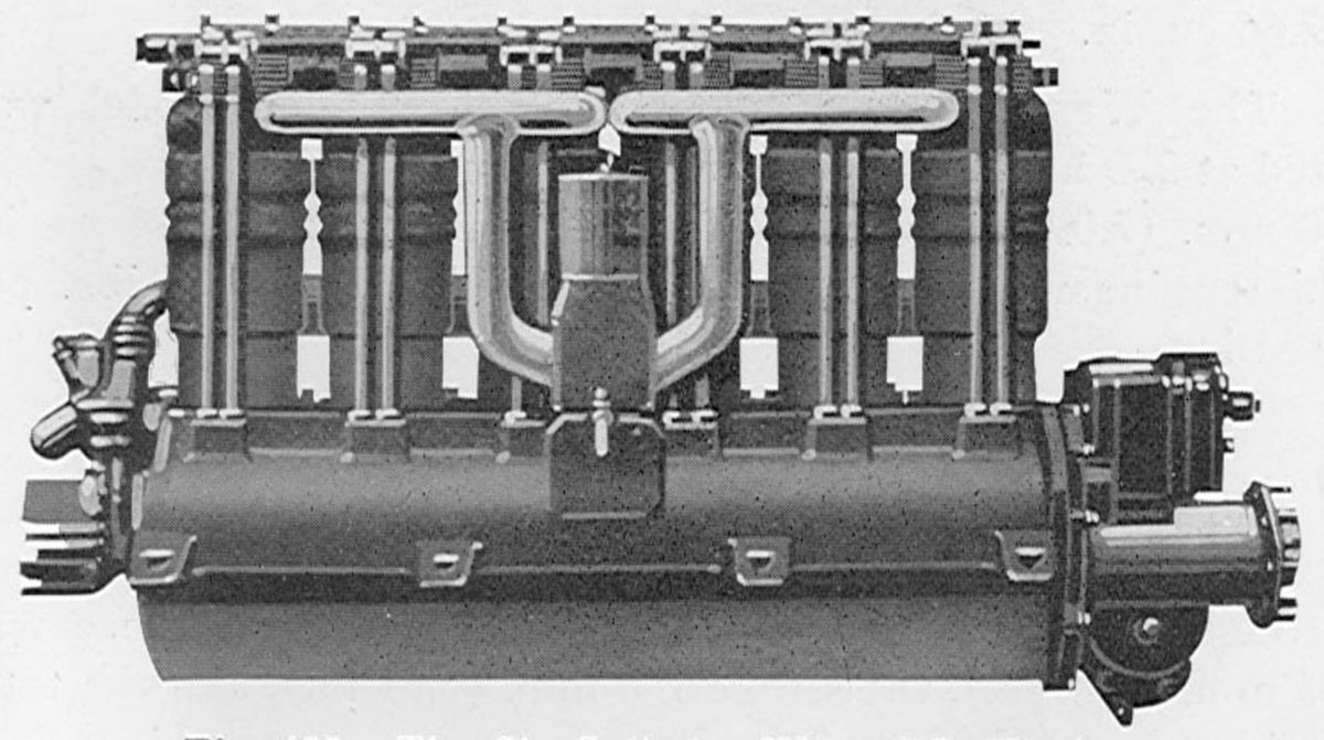 |
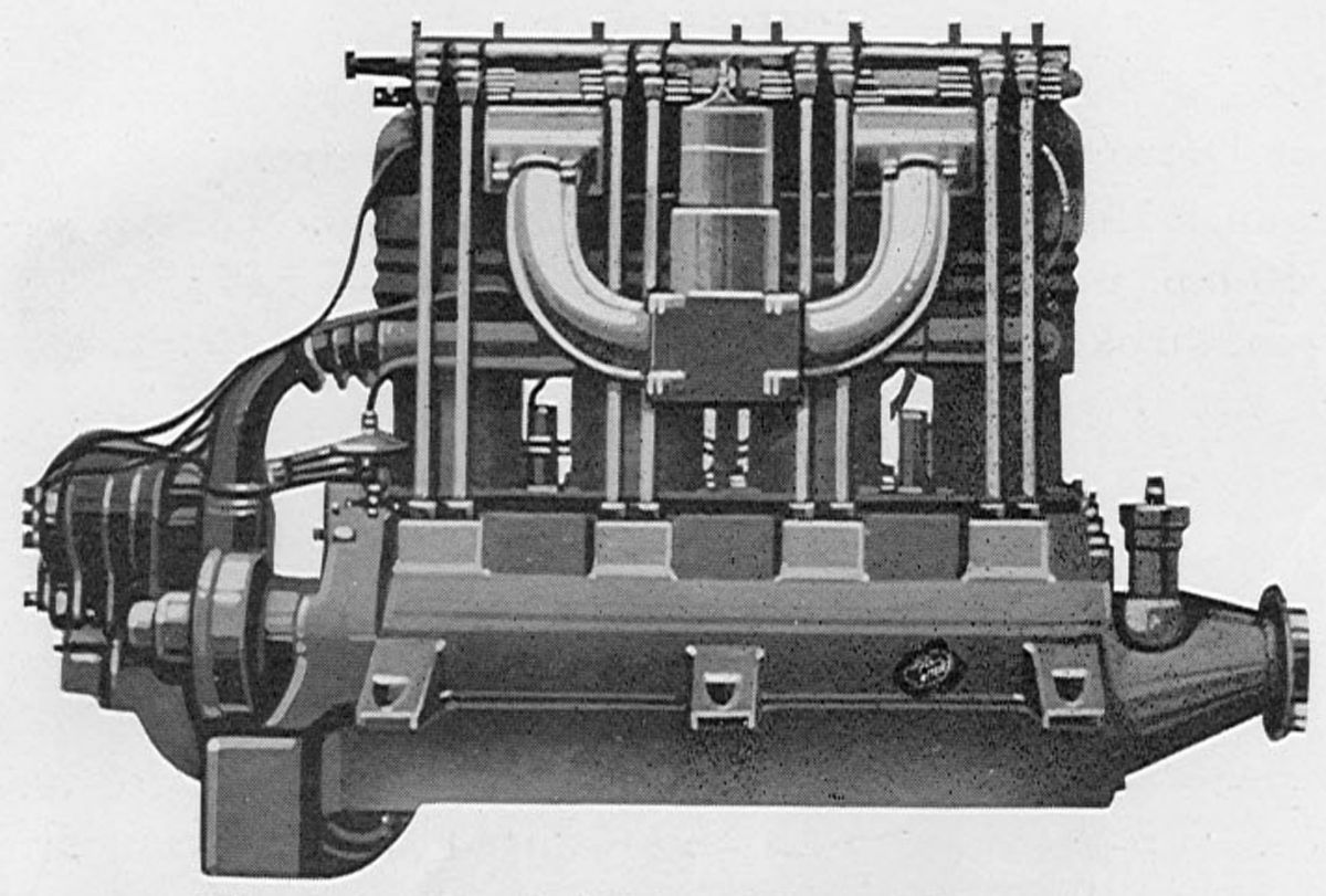
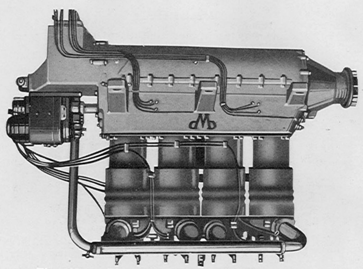
| 90/95 hp, 90/95 hp Inverted, 140/150 hp (AEE) | ||
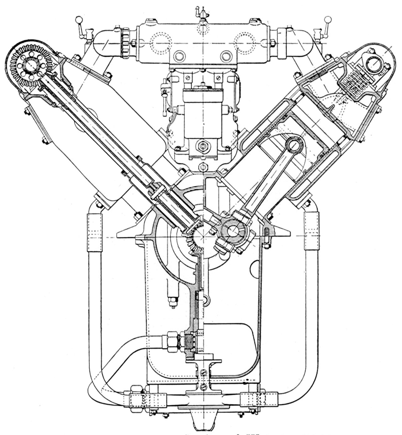
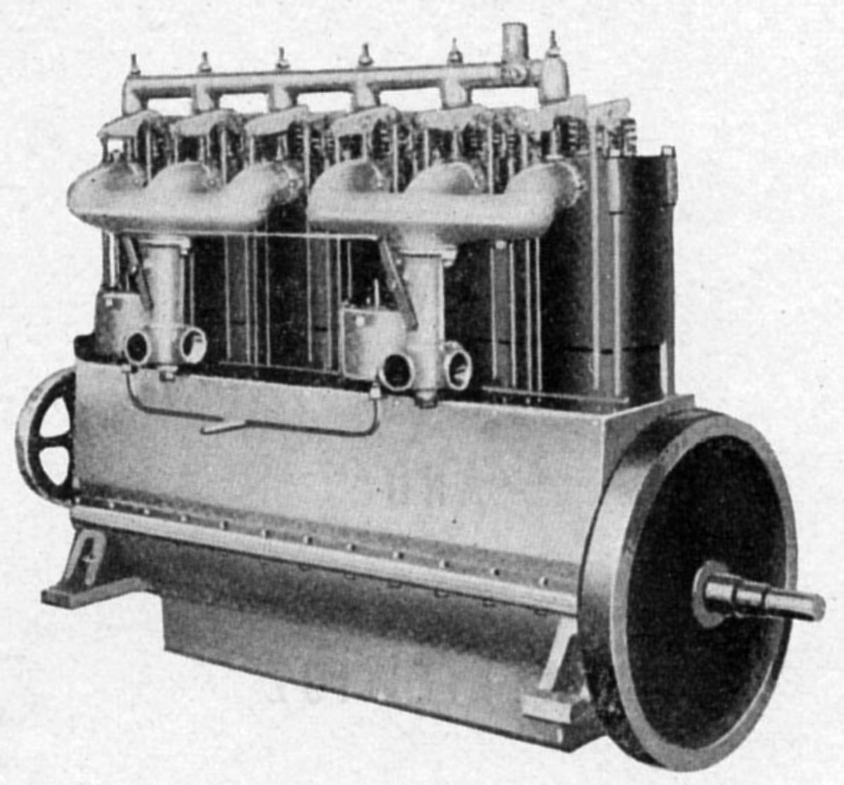
Werner & Pfleiderer, an Austrian baking equipment manufacturer, made aircraft engines for a time, beginning in 1910. Individual cylinders were turned from solid steel billets and fitted with seamless sheet nickel water jackets. Each crankshaft had main bearings on either side of a crank throw, and was supported to the upper-half crankcase by caps and through-bolts that also were used to secure the cylinders. The lower crankcase half served only as an oil pan. Lubrication was by individual piston pumps, and dual ignition by Bosch magnetos.
The 90/95 hp Werner & Pfleiderer engine was a water-cooled vertical four with a 130 mm (5.118") bore, 150 mm (5.906") stroke and 7.964 l (485.99 in³) displacement that weighed 145 kg (320 lb). A 95 hp inverted vertical four using the same cylinders was also produced.
A water-cooled vertical six with a 130 mm (5.118") bore, 160 mm (6.299") stroke and 12.742 l (777.58 in³) displacement was rated 140/150 hp and weighed 205 kg (452 lb).
A water-cooled vertical eight with a 130 mm (5.118") bore, 180 mm (7.087") stroke and 19.113 l (1,166.37 in³) displacement was rated 220 hp and weighed 270 kg (595 lb).
Western Enterprise Engine Company
 |
 |
| Western L-7-1 (A39) | |
The Western Enterprise Engine Company of Los Angeles, California produced an air-cooled radial seven-known as the Western L-7-1. The Department of Commerce granted it Approved Type Certificate No. 45 on 19 Mar 1930. With a 4.750" (120.65 mm) bore, 6.000" (152.40 mm) stroke, 744.26 in³ (12.20 l) displacement and 5.0:1 compression ratio, it was rated 130 hp at 1,850 rpm but produced 170 hp at 2,000 rpm. Fuel and oil consumptions were 0.53 and 0.025 lb/hp/hr. Weight without starter was 480 lb (218 kg), diameter was 39" (991 mm) and length was 38" (965 mm).
The L-head cylinders had their valves at the rear. The deep cast-aluminum cylinder heads were screwed and shrunk onto steel barrels that lacked any cooling fins. The head had horizontal fins around the barrel and valve pockets, and vertical or fins over the top. A break in the vertical fins appeared directly above the valves for the plugs that closed the openings used for valve insertion. The valves seated upon bronze inserts, and were operated through tappets contacting hinged levers with rollers riding a four-lobe single-ring cam. Inlet valves opened 7° early and closed 52° late; exhaust opened 52° early and closed 7° late. The aluminum-alloy pistons had flat heads and were fitted with four rings above the piston pin and one oil scraper ring near the piston skirt lower edge. The articulated connecting rods had H-section shanks. The solid master rod big end was fitted with a removable white-metal-lined bearing, and bronze bushings were used as the bearings for the piston and knuckle pins. The crankshaft was made in two sections joined by a taper-and-key on the crank pin that was made tight by a nut at the front. Three ball bearings supported the crankshaft with the two front ones carrying the propeller thrust in either direction. The main crankcase was an aluminum alloy casting joined in the cylinder plane. The nose section carried the oil pressure relief valve. The rear section had a central wall supporting the rear crankshaft bearing and guides for the valve tappets. The long bolts that held the main crankcase sections together also held the aft section, which had accessory drive provisions and cored inlet elbows that were connected to the inlet ports by straight pipes. The straight pipes used glands and nuts to seal their joints. A casting bolted at the extreme engine rear contained the inlet passages and mounting for the Stromberg NA-R7 carburetor. These passages matched with the cored elbows in the section to which this case was attached. Two Scintilla MN-7D magnetos providing dual ignition were also mounted to the rear case, along with the pressure and scavenging gear oil pumps, a single unit driven by idler shaft. The idler shaft had two gears, one driven by a crankshaft gear and the other driving the cam ring gear. Provisions existed for mounting a standard type starter to mesh with a dog clutch at the crankshaft rear.
Willis-DePalma
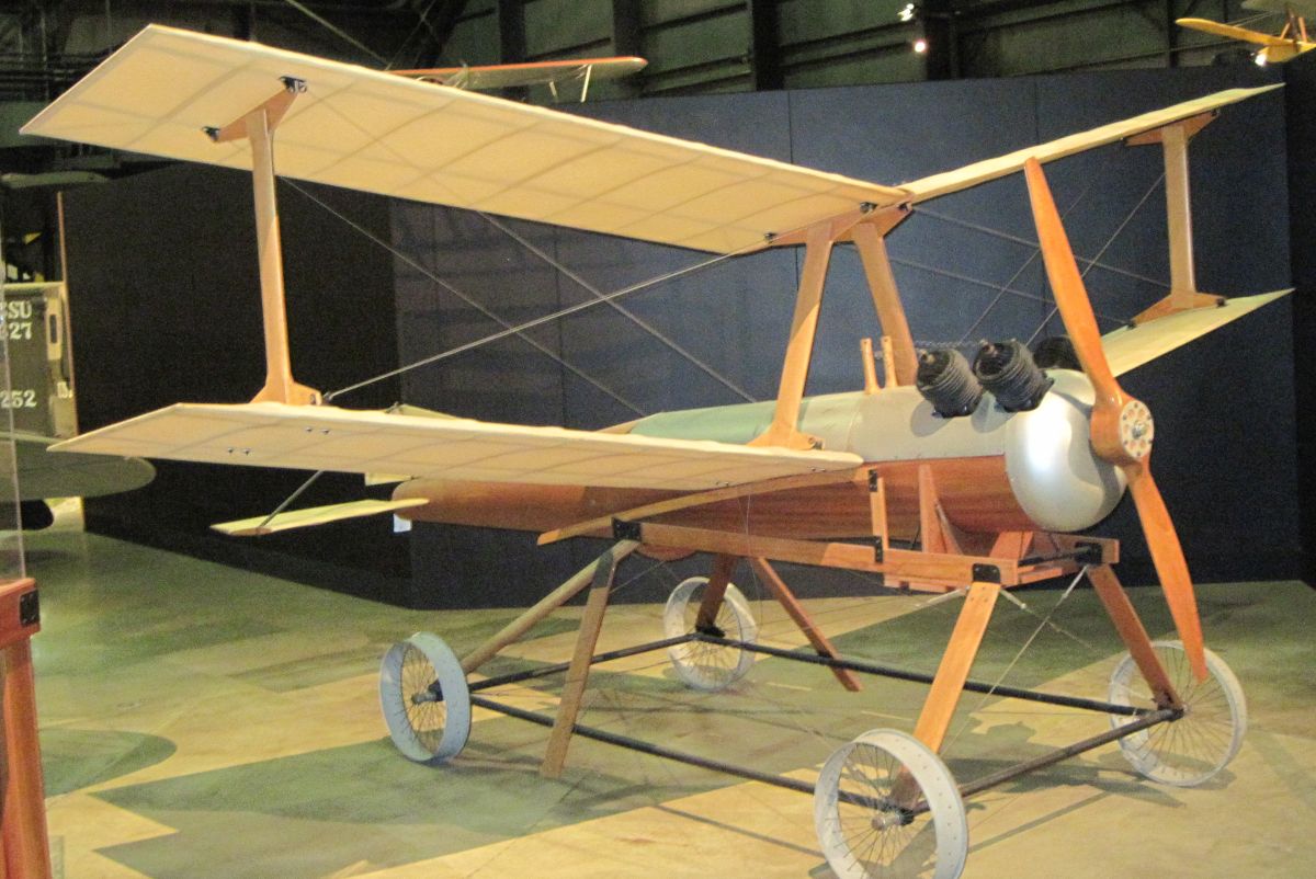
Elmer Ambrose Sperry founded the Sperry Gyroscope Company in 1910. He and his son Lawrence were interested in building equipment based on gyroscopes to automatically guide aircraft. In 1916, Lawrence and Elmer teamed with Peter Hewitt, a radio control pioneer, to develop an automatically-guided flying bomb that could carry several tons of explosives to distant targets. During WWI, the Sperrys designed a guidance and control system for Charles F. Kettering's Aerial Torpedo, aka the Kettering Bug, which first flew in 1918.
 |
| Kettering Bug (Author) |
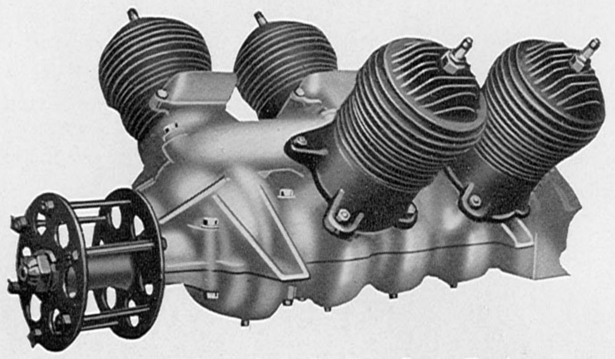
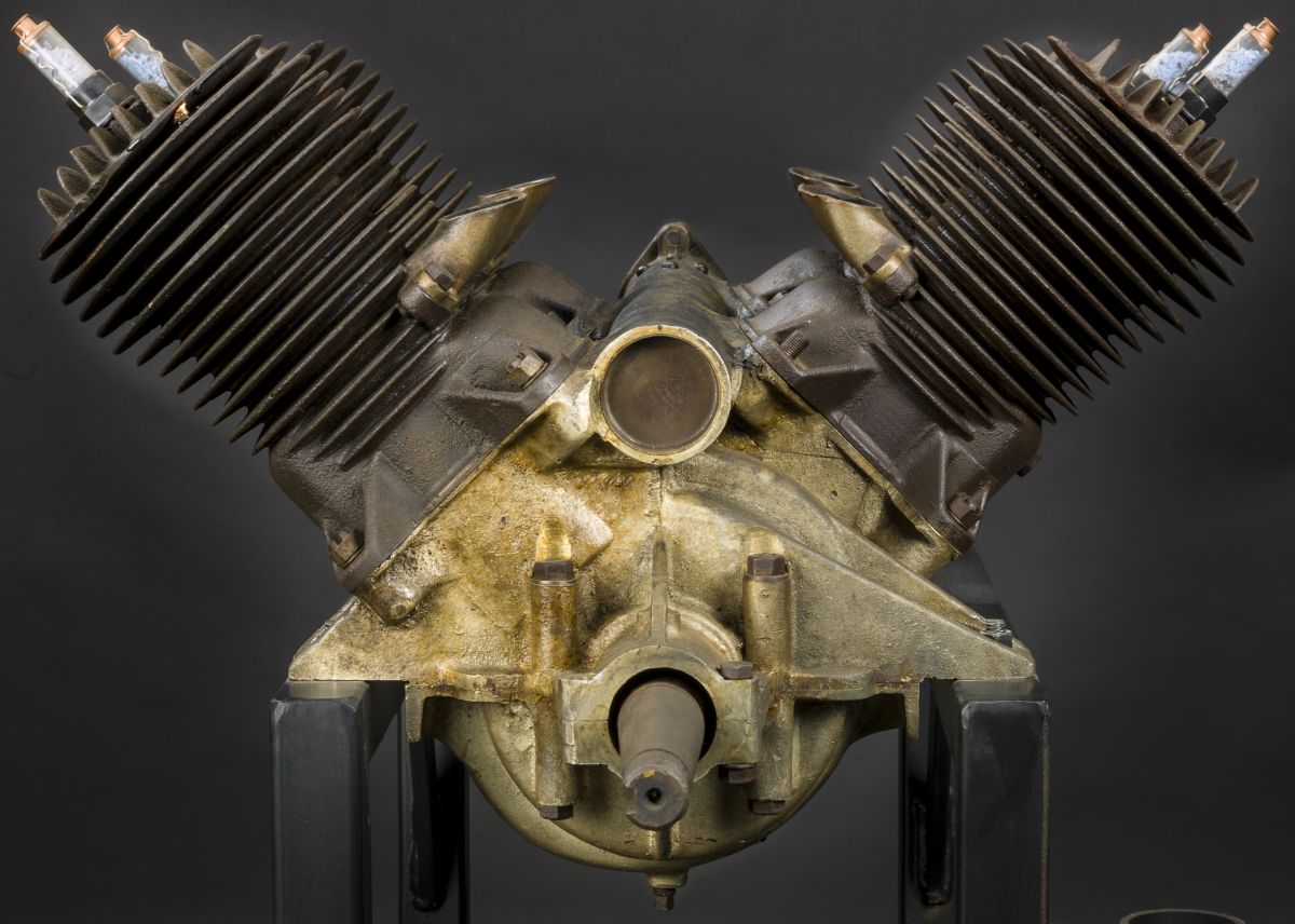
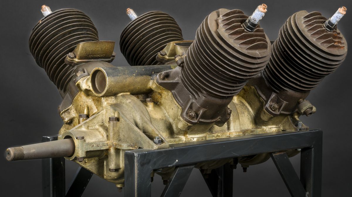
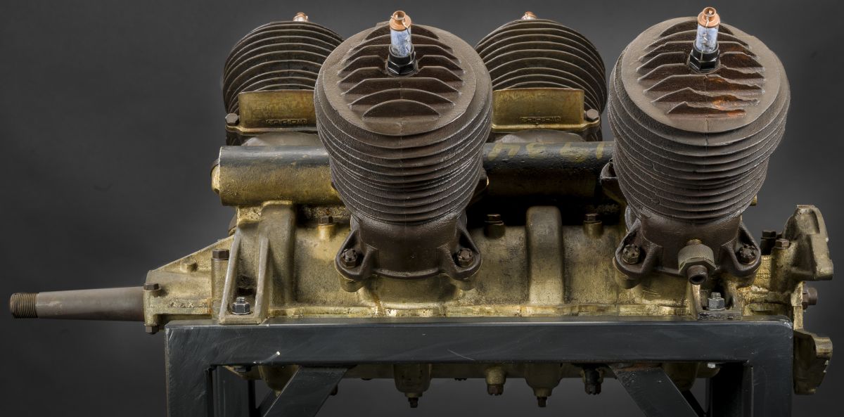
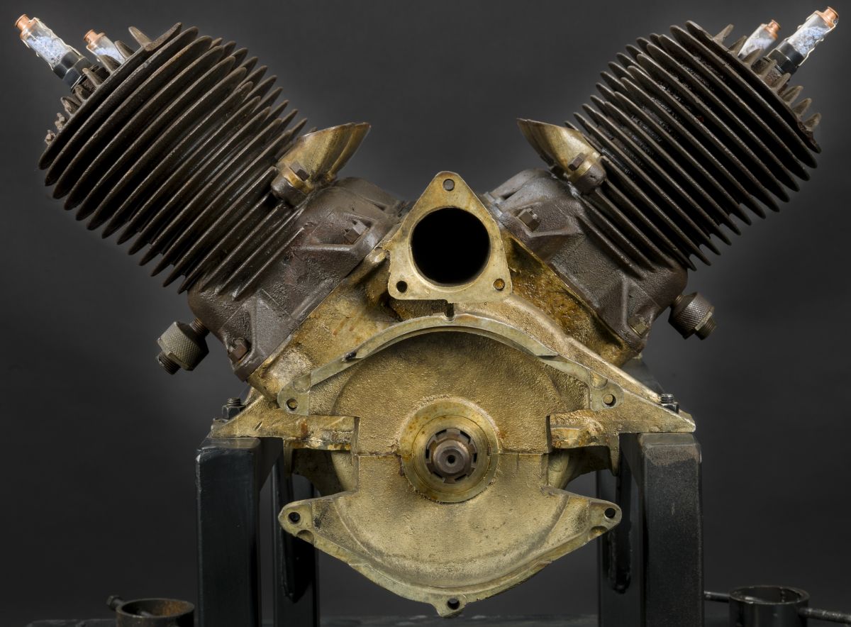
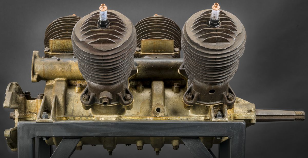
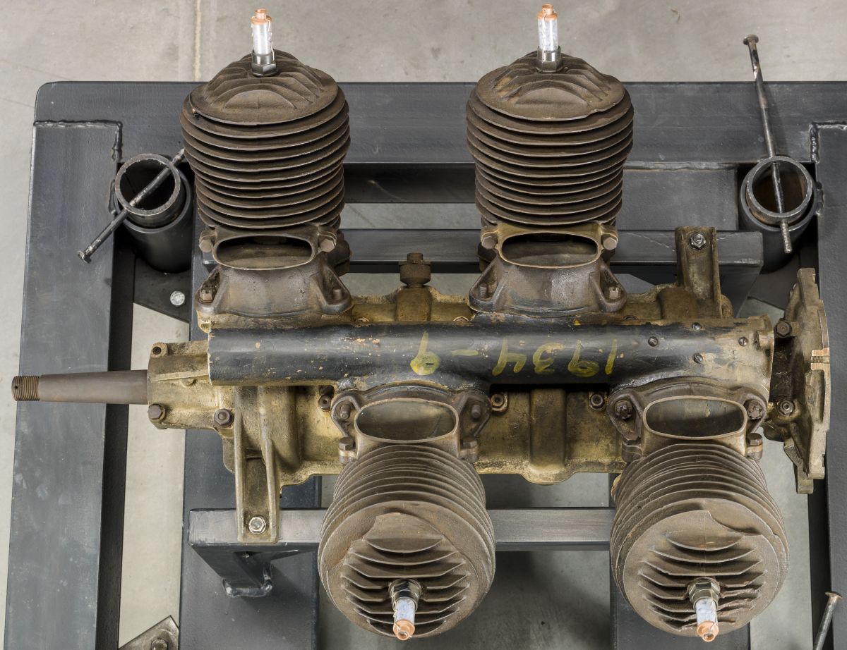
The "Bug" was powered by an air-cooled two-stroke V-4 designed by Childe Harold Willis (1 Jun 1878 - 30 Dec 1940) and built by the DePalma Manufacturing Company of Detroit, Michigan. Willis was a former Ford Motor Company chief engineer who had contributed to the Model T's design and the Liberty aircraft engine. Raffaele "Ralph" DePalma was a winning race driver who founded the manufacturing company in 1918.
The Willis-Depalma V-4 produced 38 - 50 hp. Crankcase and cylinders were made mostly of aluminum alloy. The cylinders had a pressed-in steel sleeve. It was 34.5" (876.3 mm) long, 40.0" (1,016 mm) wide and 28.0" (711.2 mm) high.
 |
 |
 |
 |
 |
 |
 |
| Willis-DePalma V-4 (AEE) | Willis-DePalma V-4 (NASM) | |||||
Please see Taint, Michael H., LTC USAF (Ret) Twenty-Five Years Ahead of its Time: The American Arial Torpedo in World War I (Columbus, Ohio: Ohio Academy of History, 2018) for a detailed account of the Kettering Bug.
Winterthur
 |
 |
| Winterthur 220 hp, 400 hp (A39) | |
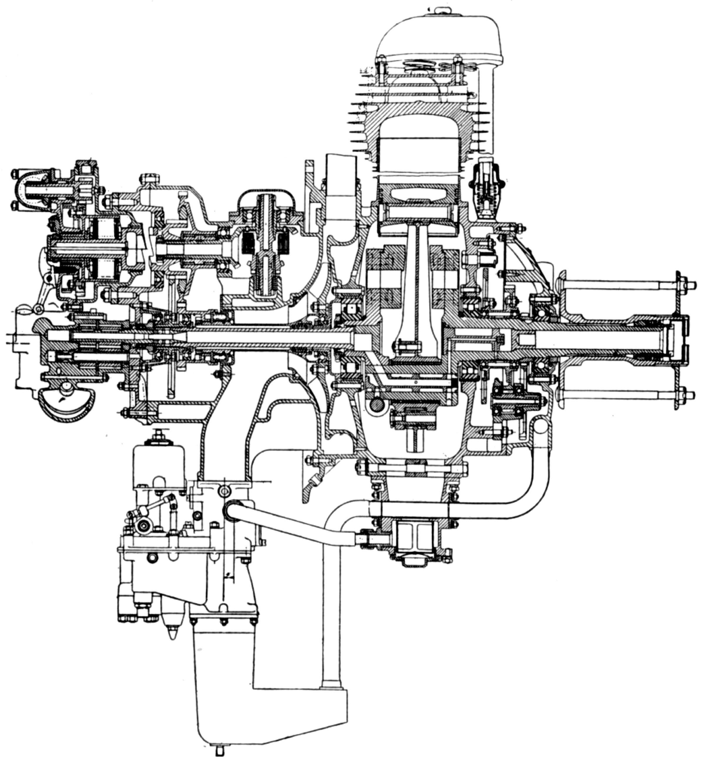
After 1920, The Swiss Locomotive and Machine Works of Winterthur, Switzerland produced water-cooled V-8 and V-12 aircraft engines.
The 90° V-8, with a 125 mm (4.921") bore, 150 mm (5.906") stroke, 14.726 l (898.65 in³) displacement and 5.5:1 compression ratio, was rated 230 hp at 1,650 rpm. Fuel consumption was 0.488 lb/hp/hr and weight was 245 kg (539 lb).
The individual steel cylinders had welded-in-place sheet tmetal water jackets. Valves, operated by push rods and rocker arms running on ball bearings, seated vertically in the cylinder head. One camshaft located in the Vee served both cylinder banks. The carburetor was situated between the cylinder banks, and two Scintilla magnetos were mounted at the rear. Twelve litres of oil could be carried in the crankcase, and the engine's water capacity was eleven litres.
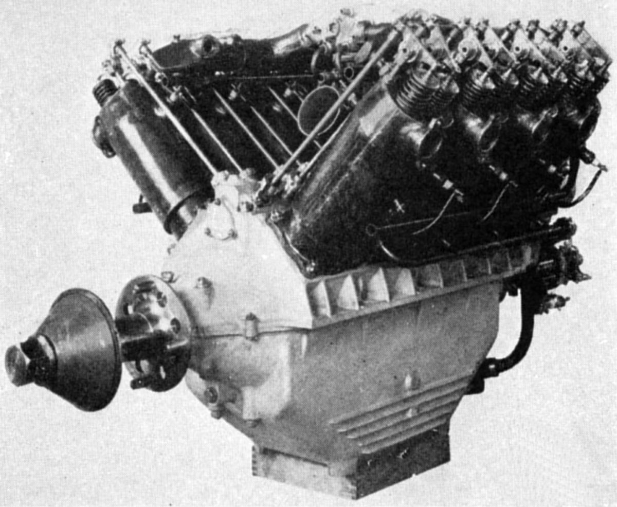
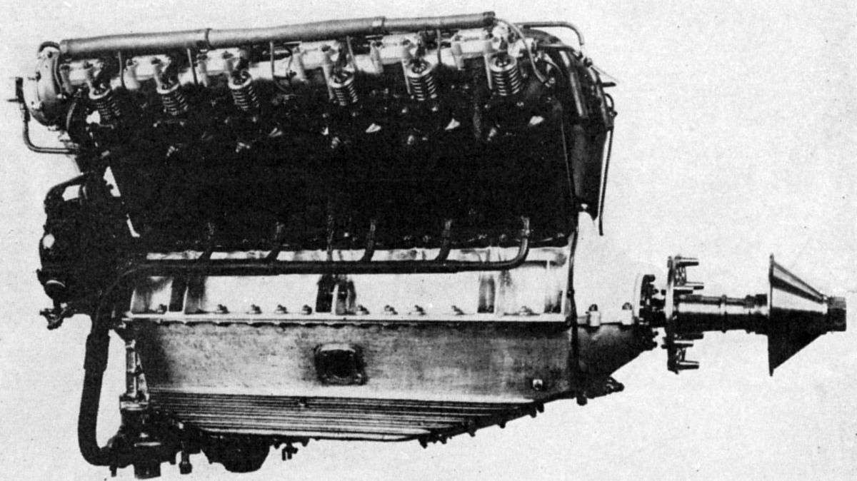
The 60° V-12, with a 125 mm (4.921") bore, 170 mm (6.693") stroke, 25.035 l (1,527.70 in³) displacement and 5.5:1 compression ratio, was rated 420 hp at 1, 700 rpm and 450 hp at 1,950 rpm. Fuel consumption was 0.488 lb/hp/hr and dry weight, minus propeller hub, was 366 kg (806 lb). The individual cylinders were built-up and welded steel, with inclined valves operated by an overhead camshaft and rocker arms. Two circulating pumps supplied lubrication from two oil sumps; one additional pressure pump and oil centrifuge was situated in the lower crankcase. A compressed air starting distributor was fitted. The Swiss Locomotive and Machine Works ultimately switched to building water-cooled Hispano-Suiza engines under license.
Wolseley
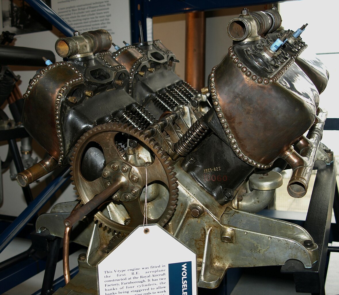
Beginning about 1907, The Wolseley Tool and Motor Car Co., Ltd., Adderley Park, Birmingham, England, built several air- and water-cooled V-8 engines of its own design. Later Renault and Maybach designs were added, and during WWI, Hispano-Suiza engines.
The first Wolseley water-cooled direct-drive V-8, with a 3.750" (92.25 mm) bore, 5.000" (127 mm) stroke and 441.79 in³ (7.240 l) displacement, was rated at 50 hp, and developed 54 hp at 1,350 rpm Fuel and oil consumptions were 0.726 and 0.28 lb/hp/hr. It weighed 300 lb (136 kg).
 |
 |
| (Wiki) | (A39) |
The next development was a water-cooled 60 hp model with a 3.750" (92.25 mm) bore, 5.500" (139.7 mm) stroke and 485.97 in³ (7.964 l) displacement. Some of these engines, with a 15 lb (6.8 kg) flywheel, weighed 366 lb (166 kg). Others weighed 294 lb (133 kg). The cast-iron cylinders were made in pairs and fitted with sheet-aluminum water jackets secured by screws. The side-by-side L-head valves were operated directly by tappets from a camshaft in the Vee. The crankshaft was carried in three plain bearings, and the connecting rods were arranged side by side on the crankpins. These engines were either geared or direct drive. An eight-cylinder Bosch magneto provided ignition, a Zenith carburetor furnished the mixture, and the cooling water and oil were circulated by gear pumps.
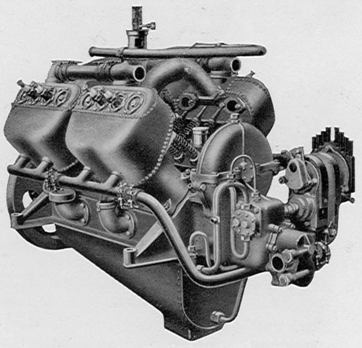
In 1910, a water-cooled 90° V-8 was built for the HMA No. 1 airship. With a 5.000" (127 mm) bore, 7.000" (177.8 mm) stroke and 1,099.56 in³ (18.019 l) displacement, it produced 147 hp at 1,200 rpm.
 |
| 75 hp (A39) |
A 1913 75 hp at 1,800 rpm, mostly air-cooled engine (it employed water-cooled exhaust valve cages with a special radiator for cooling the water) used paired cast-iron cylinders fitted with sheet-aluminum water jackets secured by screws. With a 3.750" (95.25 mm) bore, 5.500" (139.70 mm) stroke and 485.96 in³ (7.964 l) displacement, it weighed 382.5 lb (174 kg). The side-by-side valves in the L-head cylinders were operated directly by tappets from a camshaft in the Vee. The crankshaft was carried in three plain bearings, and the connecting rods were side-by-side on the crankpins. These engines were built in either geared or direct drive types. An eight-cylinder Bosch magneto provided ignition and the oil and cooling water were circulated by gear pumps. The propeller reduction ratio was 2.0:1. The steel cylinders had integral heads and cooling fins. The valves stood vertically in the cylinder head and were operated through push rods and rocker arms from a camshaft in the Vee. The valves seated in removable cages that were secured by ring nuts; the exhaust valve cage was made from welded steel and water jacketed. The steel pistons were fitted with four rings. Water circulated to the exhaust valve cages via a gear pump. The pressurized lubricating system used oil circulated by gear pumps. A high-tension magneto provided ignition.
A water-cooled V-8 design similar to the 75-hp engine, also produced in 1913, was rated 90 hp at 1,800 rpm. Its bore was 4.000", its stroke 5.500", and the displacement 552.92 in³ (9.061 l). Weight was 385 lb (175 kg) Fuel consumption was 0.6 lb/hp/hr.
A water-cooled direct-drive V-8 with a 5.000" (127 mm) bore, 7.000"(177.8 mm) stroke and 1,099.56 in³ (18.02 l) displacement developed 130 hp at 1,200 rpm and 150 hp at 1,400 rpm. Fuel consumption was 0.576 lb/hp/hr and weight was 640 lb (290 kg). Cast-iron cylinder heads containing cored water passages were screwed onto the thin steel cylinder barrels, Water jackets from spun sheet aluminum were attached to the head by screws and sealed at the lower ends by packing joints that permitted free expansion. The valves were inclined to the cylinder axis and operated by single centrally-pivoted rocker arms and pull and push rods from plus-and-minus cams on the camshaft in the Vee. The exhaust valves had water passages around the ports, and seated directly on the cast-iron cylinder heads. Inlet valves seated on screwed-in removable cages. The clear diameter of both valves was 2.3" (58.42 mm); the exhaust valve seat angle was 45° and the inlet valve seats were flat. The four-throw crankshaft was carried in three plain bearings, and the tubular-shank connecting rods were placed side by side on the crankpins. The drawn steel pistons had ribs under the crowned head and were fitted two wide cast iron upper rings and wide two phosphor bronze lower rings. Tandem gear pumps forced lubrication to the bearings. A Wolseley two-jet carburetor was situated in the Vee, and Bosch magnetos supplied dual ignition. A gear pump circulated the cooling water.
A water-cooled 90° V-8 similar to the 120-hp engine, rated 90 hp at 1,800 rpm, was originally built with a 2.0:1 propeller reduction; some were also direct-drive. The bore was 3.750" (95.25 mm), the stroke 5.500" (139.7 mm), the displacement 485.97 in³ (7.964 l), and the weight 405 lb (184 kg).
 |
 |
 |
| Viper Wiki) | Adder (A39) | |
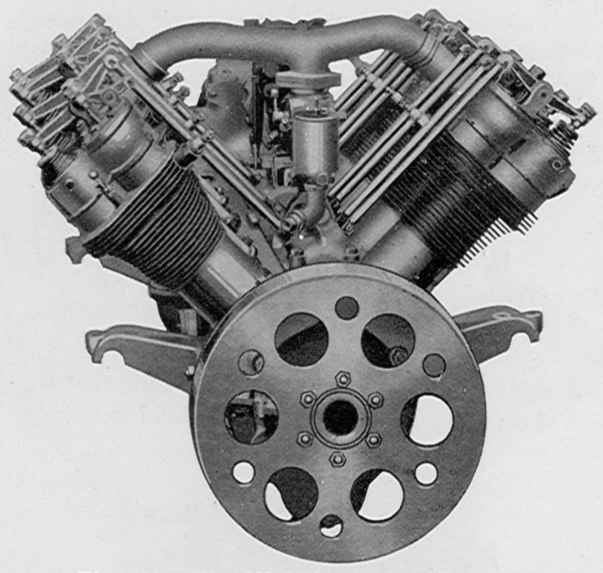
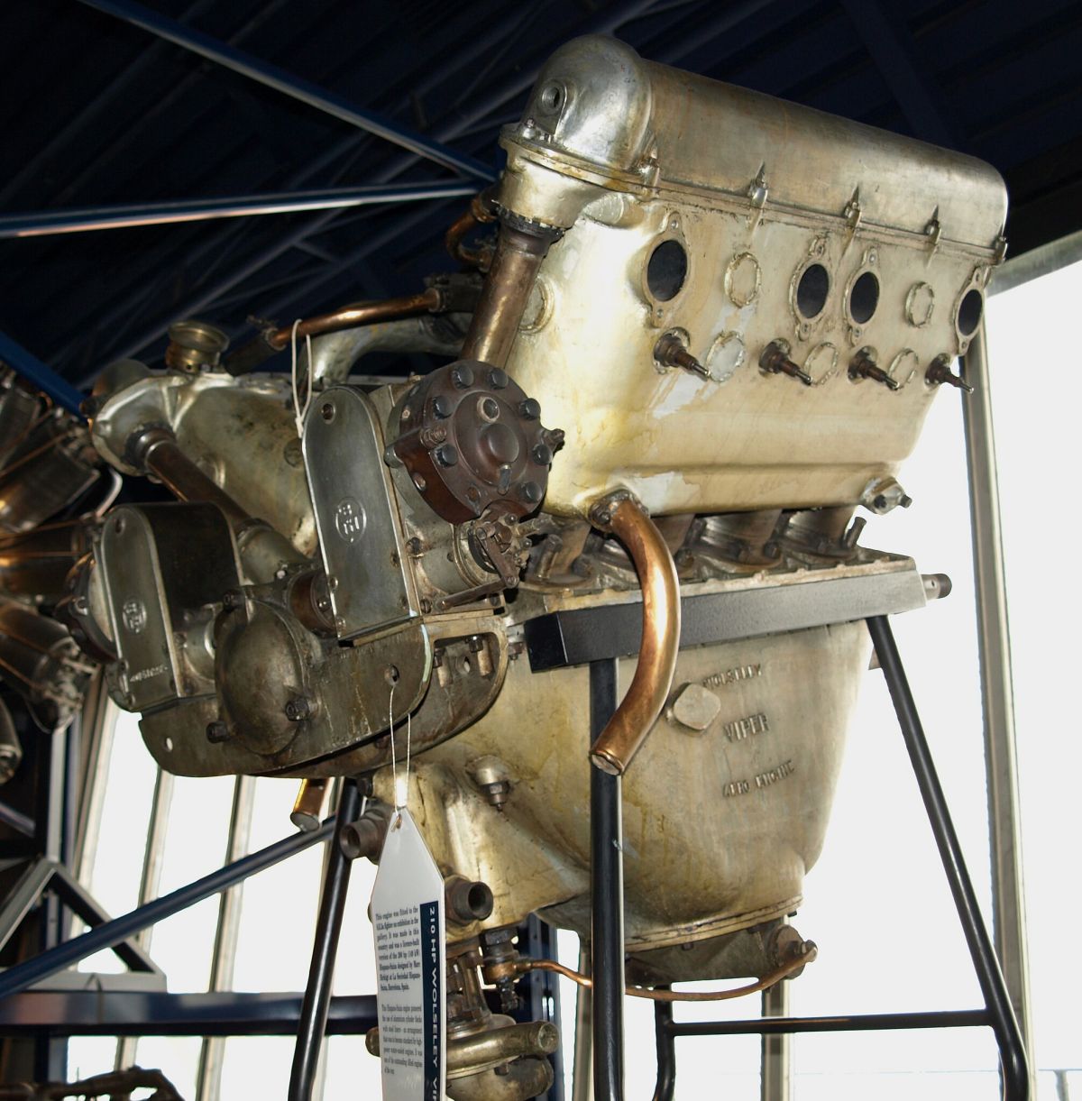
The Wolseley Python, constructed during WWI, was a water-cooled license-built 90° V-8 strongly based on the Hispano-Suiza HS-8 design, but incorporating minor structural changes. With a 120 mm (4.724") bore, 130 mm (5.118") stroke and 11.762 l (717.77 in³) displacement, it was rated 150 hp.
The Wolseley Viper, rated 180 hp, was the Python with 5.3:1 compression ratio pistons. It used twin Zenith duplex carburetors and weighed 500 lb (227 kg)
The Wolseley Adder was a 2:1 geared Python rated at 200 hp.
In 1927, the Wolseley Tool and Motor Car Co., Ltd. was reorganized as Wolseley Motors Ltd., and reentered the aircraft engine field after being acquired by Sir William Morris. The new plant was located on Drews Lane, Ward End, Birmingham 8, England. Later, Lord Nuffield became the Governing Director.
 |
| Aquarius Mk.I (A39) |
The AR.7 (Aquarius Mk.I) was a 1933 direct-drive air-cooled radial seven with a 4.1875" (106.36 mm) bore, 4.7500" (120.65 mm) stroke, 457.92 in³ (7.504 l) displacement and 5.35:1 compression ratio that produced 155 hp at 2,250 rpm and 170 hp at 2,475 rpm. Fuel consumption at 75% power was 0.518 lb/hp/hr. Its diameter was 40.25" 1,022 mm), length was 36.4" (925 mm), and weight was 375 lb (170 kg). Many Aquarius Mk.I parts were common with the Aries Mk.I
 |
 |
| Aries Mk.I (A39) | |
The AR.9 (Aries Mk.I) was a 1933 1.6103:1-geared air-cooled radial nine with a 4.1875" (106.36 mm) bore, 4.7500" (120.65 mm) stroke, 588.76 in³ (9.648 l) displacement and 5.3:1 compression ratio. It delivered 185 hp at 2,200 rpm and 203 hp at 2,420 rpm. Fuel consumption at 90% throttle was 0.533 lb/hp/hr. Oil consumption ranged from 3.0 to 4.5 pints per hour. Dry weight was 452 lb (205 kg), diameter was 41.25" (1,048 mm) and length was 38.25" (972 mm).
The cylinders used forged steel barrels that were screwed and shrunk into cast aluminum alloy heads. The machined-all-over cylinder barrels had close-pitched shallow fins. A steel band with two circular fins was pressed over the head lower end to reinforce the joint and prevent leakage. Single inlet and exhaust valves were interchangeable, being produced from nickel-chromium steel. These valves worked in hard phosphor-bronze guides, and seated upon monel metal seat inserts that were screwed and shrunk into the cylinder head. The valves were operated through fully enclosed push rods and rocker arms from a single-ring five-lobed cam at the engine front, which was driven at 1/10 crankshaft speed, in the same direction as the crankshaft, by means of a double-hardened spur gear train supported on ball bearings. Since each cam operated inlet and exhaust valves, the total opening period of 252° was common to both. With a 0.045" hot-tappet clearance, inlet valves opened 12° early and closed 60° late and the exhaust opened 60° early and closed 12° late. The valve timing was accomplished through angular adjustment of a vernier attachment between the cam gear and its carrier. The tappets were carried in long bronze guides, and were actuated through rockers that had rollers at each end and were pivoted on hardened steel spindles attached to the crankcase front wall . The push rods were steel tubes with hardened steel cups at each end, and the rocker arms were carried upon needle roller bearings supported in brackets secured to the cylinder head. These brackets were prevented from loosening by hollow securing screws whose ends were split longitudinally; once in place, they were expanded in the cylinder head boss by a draw bolt and its conically-formed nut. The covers that enclosed the valve gear were of pressed aluminum held in place by self-locking thumb screws. Each valve had double springs and a special hardened steel button fitted to the valve stem ends reduce wear. Full-skirted heat-treated forged Y-alloy pistons were provided with two compression rings and an oil scraper ring above the piston pin and one oil scraper ring below. A series of oil return holes were drilled underneath each oil scraper ring. The piston pin was full floating, located endwise by circlips in piston pin boss grooves.
The articulated connecting rods had H-section shanks and were finished all over. The master rod big end carried a floating steel bushing coated inside and out with white metal, and provided with numerous oil holes to ensure adequate lubrication. Hard phosphor-bronze bushings were provided for both piston-pins and wrist-pins, and arranged so that the oil supply would be maintained even if they turned in their bosses. One end of each knuckle pin was tapered to fit into a corresponding hole in a master-rod big end side flange. These were drawn tightly in place by set screws, and in addition, a key was provided to prevent knuckle pin rotational movement. The set screws were locked by plates, each of which was fitted over the head of one screw and was held under the head of the adjoining one; they were finally held to the master rod by a single stud and nut. The single-throw crankshaft was made in two sections, the rear section with a maneton joint was attached to the crankpin by means of a key and clamped eye, with the pinch bolt for the latter arranged of a definite length, so that when tightening the nut the stress in the bolt could be limited by measuring the bolt elongation. The crankshaft was supported upon four bearings ‑ two roller bearings at the engine front and two ball bearings at the rear. One of the latter, supported in the crankcase rear wall, maintained the endwise crankshaft location . The hollow crankpin was fitted with a removable aluminum plug, that provided a continuous oil-way of uniform section, and also trapped foreign matter so that it might be cleaned whenever the plugs were removed. The internal reduction gear employed a 23-tooth hardened spur gear, driven by the crankshaft and supported by heavy high-duty roller bearing carried in a duralumin stamping attached to the crankcase. This pinion engaged with a hardened internal ring gear having 37 teeth, which in turn was attached to the propeller shaft flanged end. The reduction gear housing formed a complete assembly that was easily detached for inspection. The propeller shaft was supported by two bearings. One of these was a large diameter roller bearing situated directly over the internal ring gear, and it absorbed the journal loads imposed by that gear. The deep-groove ball bearing at the forward end carried both radial and thrust loads. The propeller hub was attached to the shaft by splines, with bronze centering cones located at each end. The crankcase sections were made from heat-treated duralumin forgings. The main section was made in halves and joined in the cylinder plane. A cast Elektron ring, which formed part of the induction system, was attached to the crankcase rear. Sandwiched between this ring and the crankcase, attached by 27 bolts, was a pressed-steel conical plate used for mounting the engine. The front crankcase half, which contained the cam and tappet gear, was closed by a duralumin stamping. This in turn carried the front crankshaft roller bearing. Steel stampings were shrunk and bolted to the crankcase to form housings for the ball and roller bearings. The mixture was furnished by a Claudel-Hobson Type A.V.64B carburetor. This carburetor included a manual mixture control, as well as an accelerator pump connected to the throttle. A completely machined annular gas chamber was attached to the crankcase rear and it was fed at two points by an inlet branch with an oil jacket through which hot scavenge oil was circulated to warm the mixture. Each cylinder was fed from the annular gas chamber by means of aluminum pipes attached to the inlet ports by cast Elektron elbows. The cylinders could be removed without detaching the pipes, and these pipes had glands of special material where they were attached to the annular gas chamber. Two B.T.H. Type S.C.9 magnetos provided dual ignition. Both magnetos turned clockwise, being driven through bevel gears and a spring drive having a stop to limit angular displacement. The magnetos were set at 36° advance. When radio was used the ignition could be completely shielded. A pressure-fed dry-sump lubrication system used gear-type oil pumps, with the scavenging pump having twice the capacity as the pressure pump. A pressure of 40 – 50 psi was maintained, and a relief valve was arranged to open if the oil filter pressure differential exceed 6 psi. Oil was delivered to all engine parts, including the reduction gears and thrust bearing. Either mineral, castor or compounded oils might be used.
A circular flange at the engine rear was provided for starter attachment. Either a Wolseley hand-turning gear or an Eclipse inertia starter could be fitted. The hand-turning gear comprised a dog clutch driven by a bevel and spur gear train through a friction clutch, the dog clutch being engaged with a corresponding engine clutch by means of a hand lever which that could be operated from the cockpit of the airplane. A ratcheting device was incorporated in the starting gear so that the clutch would slip in event of backfire and thus prevent any possible injury to the operator. The ratio between the starting handle and the crank was 8:1. A priming system was utilized to facilitate starting under extreme conditions.
The AR.9 (Aries Mk.III) was a refined AR.9 released in 1935. Geared 1.5898:1, it retained the 4.1875" (106.36 mm) bore, 4.7500" (120.65 mm) stroke and 588.76 in³ (9.648 l) displacement. With the compression ratio raised to 5.35:1, it delivered 225 hp at 2,475 rpm. Fuel consumption at 75% throttle was 0.517 lb/hp/hr. Dry weight was 510 lb (231 kg), diameter was 41.25" (1,048 mm) and length was 42.00" (1,067 mm).
The Aries Mk.III propeller reduction featured an internal 83-tooth gear attached to a carrier that freely rotation on a crankshaft extension. Dogs at the carrier forward end were driven from corresponding tongues on a long quill shaft that extending through the hollow crankshaft to the front crank cheek, where it engaged serrations. This provided a resilient reduction gear drive that eliminated torsional vibration effects within the engine's operating envelope. A 49-tooth sun gear was anchored to the nose section by bolts that also secured the thrust bearing race. The propeller shaft had a spider supporting six 17-tooth planet pinions; the shaft was supported by a ball thrust bearing in the nose piece, and by a white-metal bearing on the internal gear carrier boss outside diameter. Consequently, the propeller shaft with its planet pinions and sun gear formed an assembly that could be detached readily for inspection.
The Aries Mk.III engine incorporated an induction impeller running at 3.8 times crankshaft speed. The impeller gave a slight positive pressure, but its main purpose was to provide better mixture distribution. The passage leading to the impeller was surrounded by an oil jacket through which the hot scavenged oil passed. Each cylinder received its charge via the annular gas chamber and a radial aluminum pipe that was connected to the cylinder port by a cast elbow.
 |
| Scorpio (A39) |
The Scorpio Mk.I was a 1.5898:1-geared radial nine sharing many features with the Aries series. With a 4.375" (111.13 mm) bore, 642.66 in³ (10.531 l) displacement and 5.4:1 compression ratio, it was rated 230 hp at 2,250 rpm and 250 hp at 2,475 rpm Dry weight was 536 lb (243 kg), diameter was 42.25" (1,073 mm) and length was 42.15" 1,071 mm). The valves were operated through push rods from self-adjusting hydraulic tappets contacting a single five-lobed cam turning at 1/10 crankshaft speed in the same direction. Inlet valves opened 20° early and closed 70° late; exhaust valves opened 70° early and closed 20° late. Both valves had a 270° opening period.
In 1936, Wolseley introduced the Libra, a larger geared air-cooled radial nine that followed the smaller models in general design. Normally rated 440 hp, 495 hp was the maximum available for take-off, and 505 hp was delivered at an altitude of 7,300 ft (2,225 m). This engine operated on 87 octane fuel at 6.5:1 compression ratio. Dry weight was 725 lb (329 kg).
Wolseley abandoned aircraft engine manufacture in the fall of 1936, and about one year later the firm's name changed to Nuffield Machanizations and Aero, Ltd.
Wright Brothers
The engines built by Wilbur and Orville Wright are of special historic importance since the original model powered their flight on 17 Dec 1903. These engines were designed and constructed in the Wright Brothers own shop, with the valuable aid of their assistant, Charles E. Taylor. Licenses to build their designs were granted later to some early European airplane engine manufacturers.
 |
 |
| Wright Brothers 4-cylinder, 6-60 (A39) | |
The 1903 was a water-cooled horizontal inline four with a 4.000" (101.6 mm) bore and stroke, and 201.06 in³ (3.295 l) displacement. Complete with radiators, tanks, water and fuel, the unit weighed slightly over 200 lb (91 kg). For the first fifteen seconds after starting, it developed 16 hp at 1,200 rpm. After the engine ran for one or two minutes, the output dropped to 13 - 14 hp.
The Wright airplanes of 1901 used a similar engine with a 4.125" (104.78 mm), giving a 207.35 in³ (3.398 l) displacement. For the first fifteen seconds after starting, this engine produced 24 hp at 1,500 rpm. However, the output dropped to 16 - 17 hp after a few minutes running. This engine, including water, fuel and other accessories, weighed 240 lb (109 kg).
With a few modifications to the oiling device and carburetor, engines of this same design were used for all 1905 flights. They showed a 3 hp gain over the previous year's model, which was attributed mainly to manufacturing improvements. By virtue of increased manufacturing experience and design improvements, Wright brothers' engine output and reliability steadily improved. A water-cooled vertical inline four with a 4.375" (111.13 mm) bore, 4.00" (101.6 mm) stroke and 240.53 in° (3.942 l) displacement delivered 39 hp at 1,600 rpm and weighed 180 lb (82 kg).
The individual early-Wright cast-iron cylinder barrels were jacketed with thin aluminum, with no provision for head cooling. Interchangeable valves stood vertically in the cylinder heads, the inlets operated automatically, and the exhaust valves by means of push rods and rockers from a camshaft in the crankcase. The connecting rods had tubular shanks. The crankshaft was fitted with a flywheel and two sprockets that drove two propellers by chains at a 125:34 ratio. No carburetors were used; a small gear pump discharged fuel into the open bell-mouthed inlet pipe end through a small jet orifice that regulated the fuel quantity to each cylinder. Pressure lubrication was by a gear pump driven from the camshaft. A centrifugal pump circulated cooling water and a Mea magnetos furnished ignition.
A six-cylinder vertical type, using the same 4.375" (111.13 mm) bore cylinders as the larger four-cylinder design had a 360.79 in³ (5.912 l) displacement, was rated 50 hp at 1,150 rpm and weighed 230 lb (104 kg). A 90° V-8 using the same cylinders displaced 481.06 in³ (7.555 l) and was rated 60 hp.
The Wright Model 6-60 was a water-cooled inline six with a 4.375" (111.13 mm) bore, 4.500" (114.30 mm) stroke and 405.89 in³ (6.651 l) displacement. It was rated 60 hp at 1,400 rpm but developed from 72 - 75 hp at 1,560 rpm. Dry weight was 300 lb (136 kg), length was 41" (1,041 mm), width was 15" (381 mm) and height was 27" (686 mm). All but a few of the original design features of the four-cylinder engine were retained. The cylinders, which had integral cast iron water jackets, were secured by long studs extending to lugs on the cylinder heads. Two Zenith carburetors supplied three cylinders each.
References
Angle, Glenn D, ed. Aerosphere 1939 (New York, New York: Aircraft Publications, 1940).
Anble, Glenn D, ed. Airplane Engine Encyclopedia (Dayton, Ohio: Otterbein Press, 1921).
Image Sources: A39 = Aerosphere 1939; AEE = Airplane Engine Encyclopedia; Flt = Flight Magazine; NARA = U.S. National Archives and Records Administration; UKNA = United Kingdom National Archives; Wiki = Wikimedia Commons (mouse over for details).
Send mail to
![]() with questions or comments about this web site.
with questions or comments about this web site.
![]()