(RR-HT)
Selected Early Engines
R.A.F., Rapp, Rausenberger, Renard, Renault, R.E.P., Rheinische, Roberts, Rolls-Royce
Compiled by Kimble D. McCutcheon
Published 20 Feb 2023; Revised 13 Apr 2023
Rolls-Royce
Great Britain entered WWI on 4 Aug 1914. On Friday, 7 Aug 1914, the Rolls-Royce Board resolved "... the Company should not avail itself of the opportunity now possibly arising of making or assembling aero engines for the British Government." This startling position was probably championed by Ernest Claremont, the risk-averse Chairman, who believed the fighting would be over by Christmas 1914! The British War Office protested the decision, pointing out that the French Government was claiming the entire Renault engine manufacturing capacity, which would leave the Royal Flying Corps without an engine for its BE2 aircraft. At an emergency meeting on 14 August, the Board reversed its decision, an action probably helped by the War Office's promise to buy 100 Renault 80-hp V-8 aircraft engines that Rolls-Royce would under license and sell at a hefty profit. With the civilian luxury auto market stifled by the War, this decision kept the Company cash flow intact. Sometime before 19 August, Henry Royce decided to design an aircraft engine that would be superior to anything else available. Only 43 days later, on 16 Sep 1914, the first detailed drawing, for the cylinder, was released. Thus began Rolls-Royce aero engines.
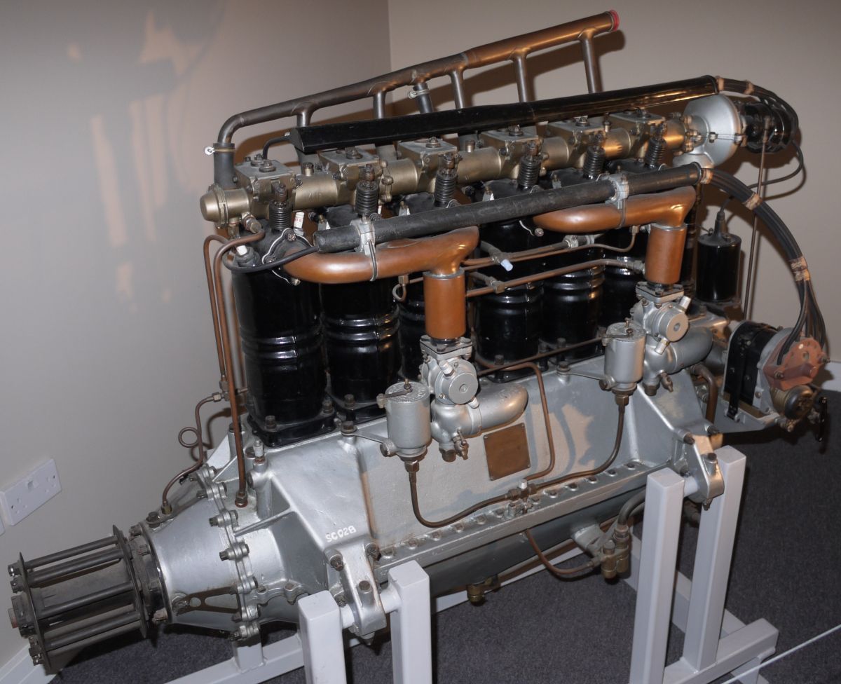
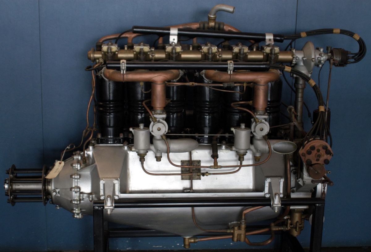
Several early designs were built and tested, including a water-cooled vertical eight rated 90 hp. The first production Eagle, which like nearly all Rolls-Royce piston engines was named after birds of prey, was completed on 18 Oct 1915. [Taulbut, Derek S. Eagle: Henry Royce's First Aero Engine (Derby, England: The Rolls-Royce Heritage Trust, 2011)]
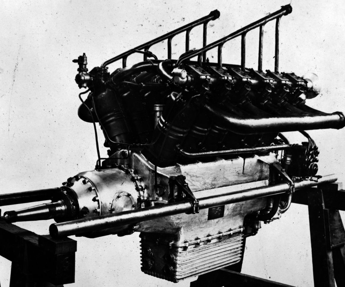
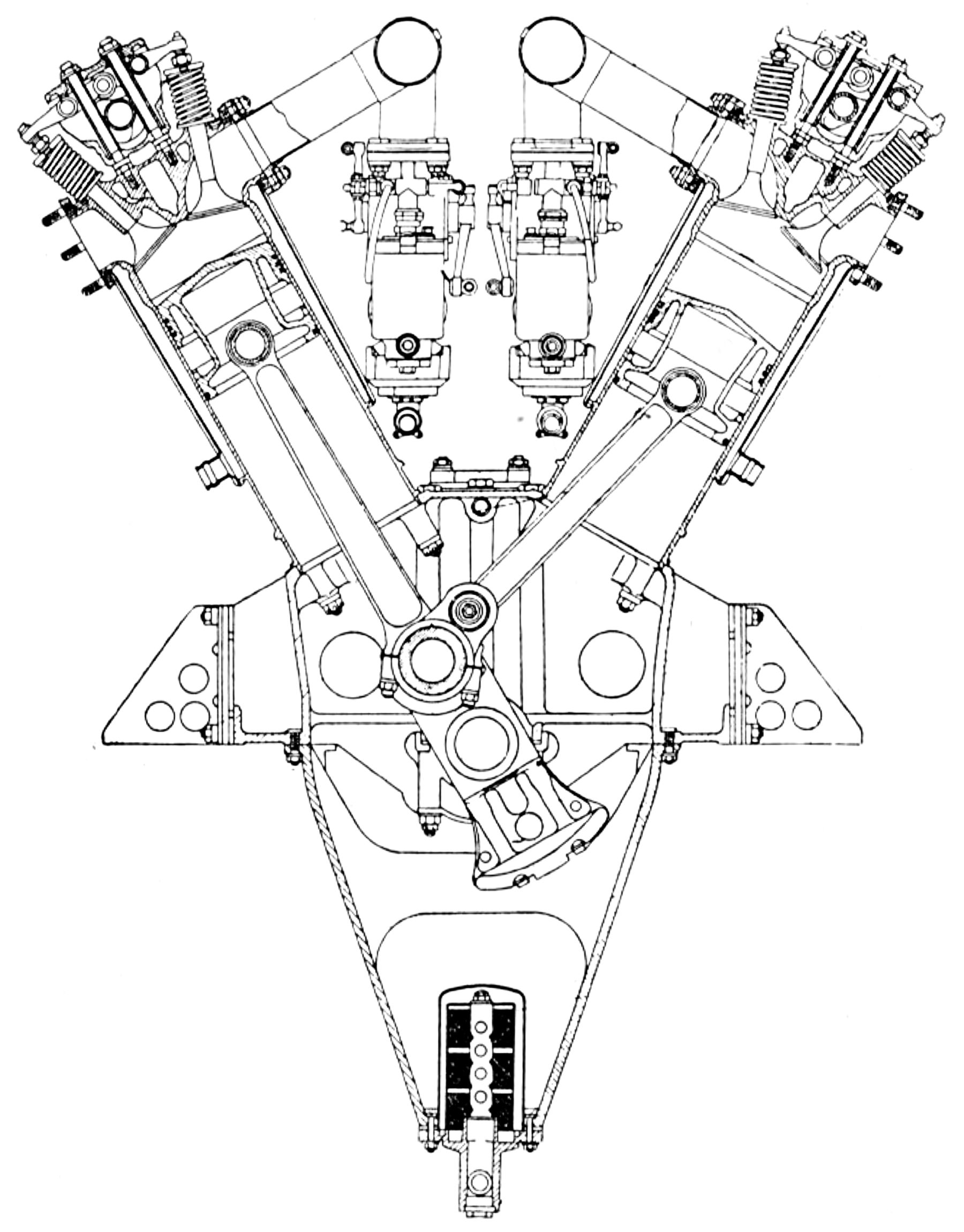
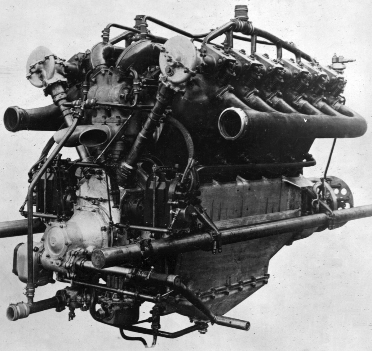
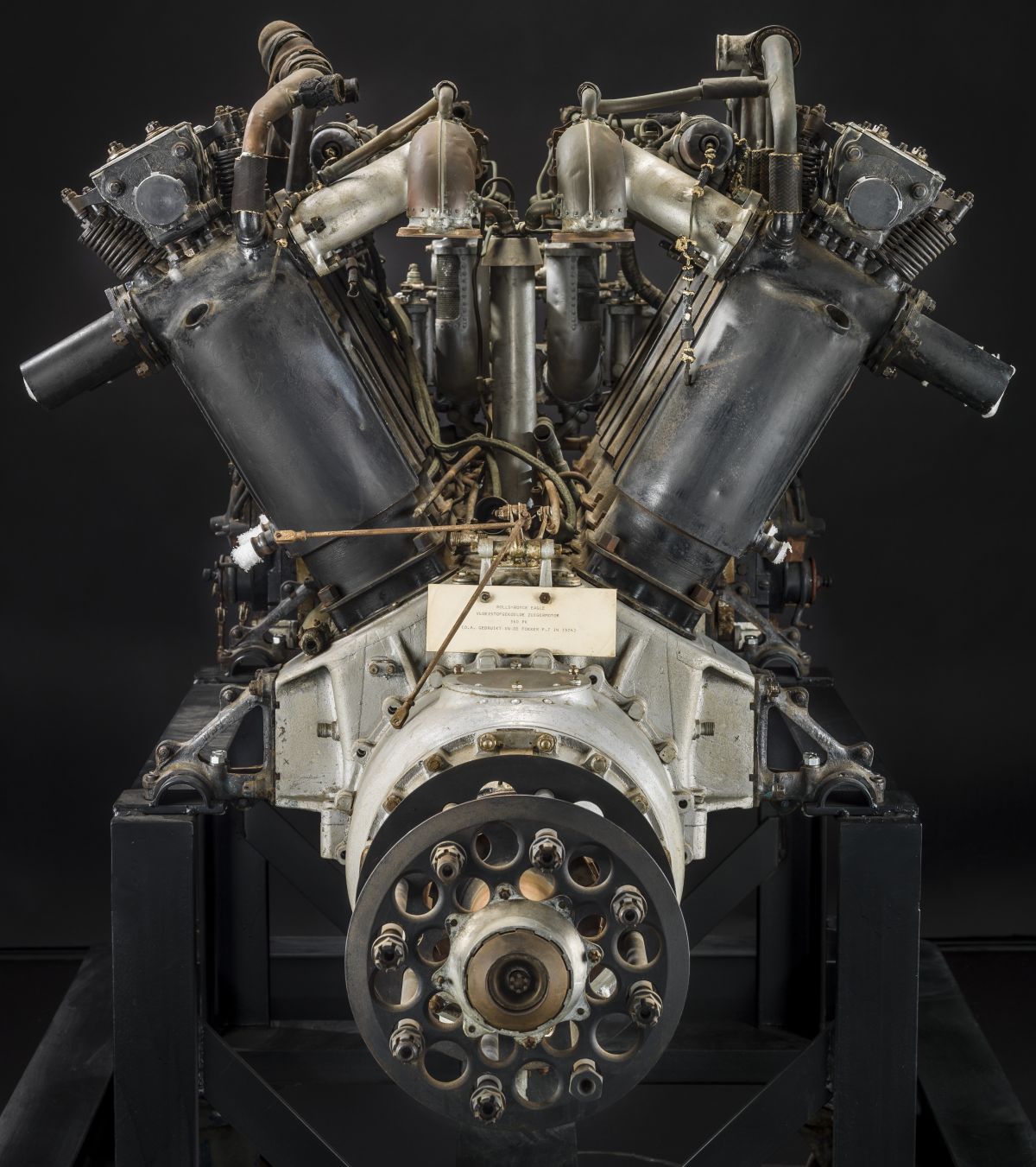
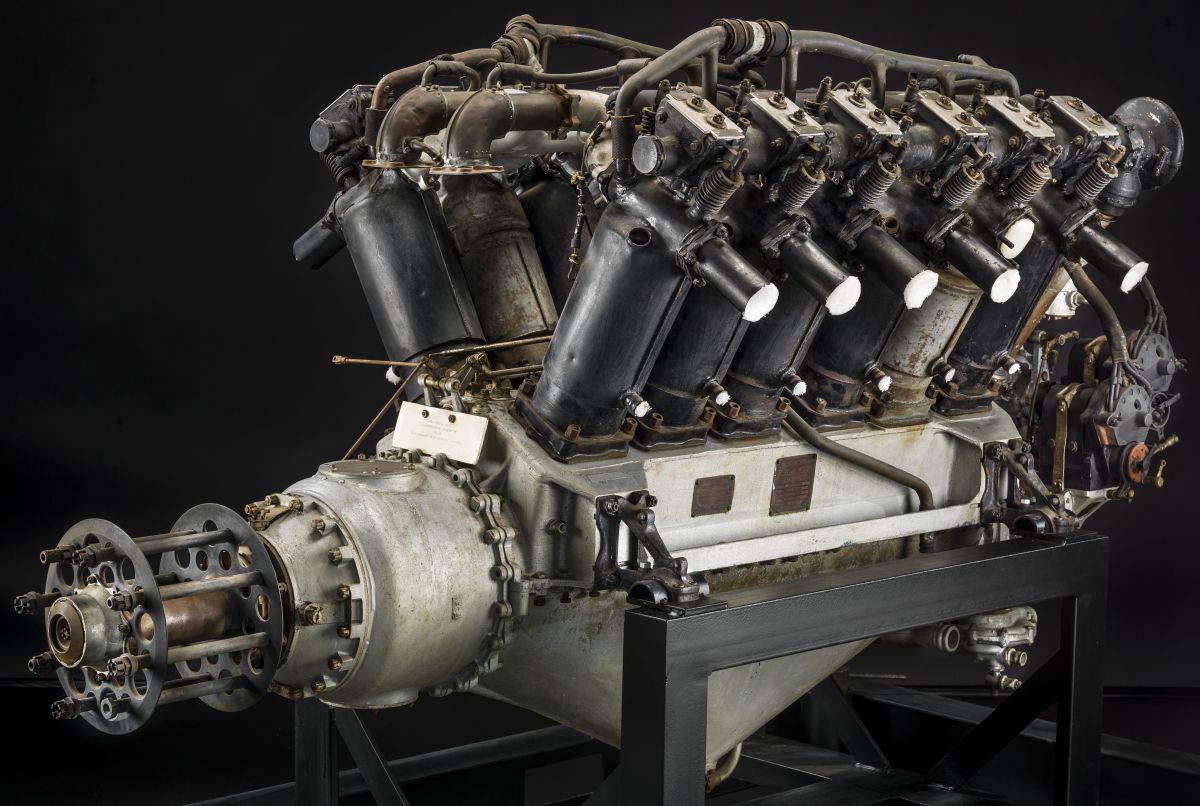
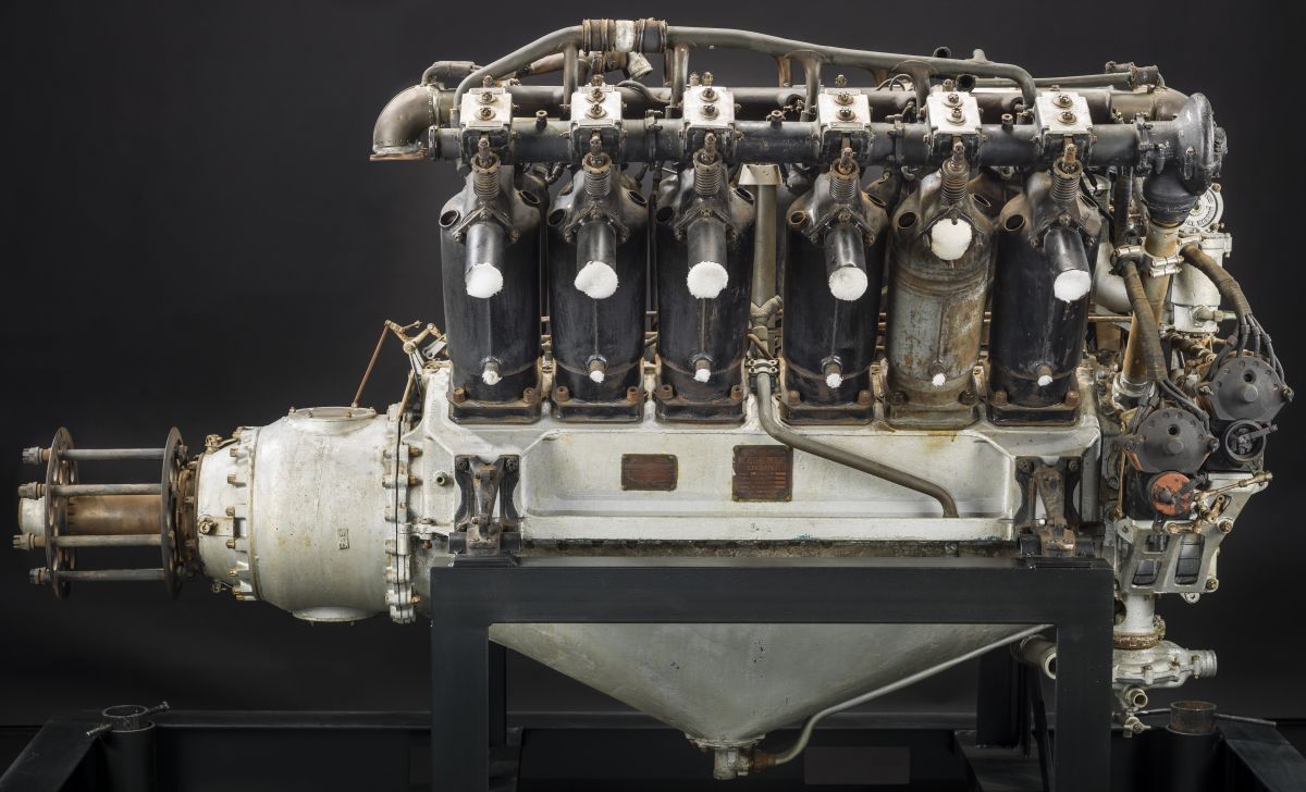
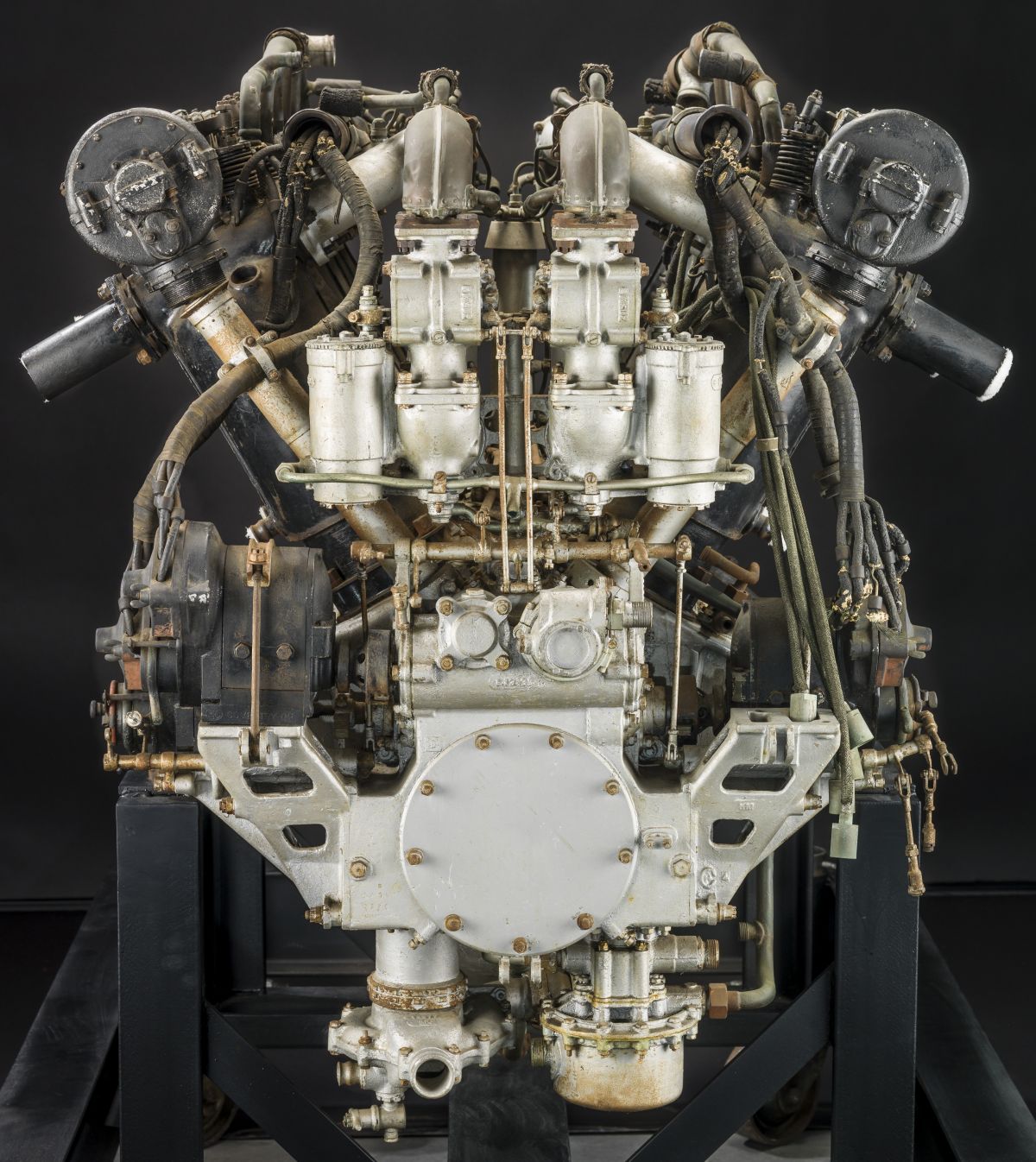
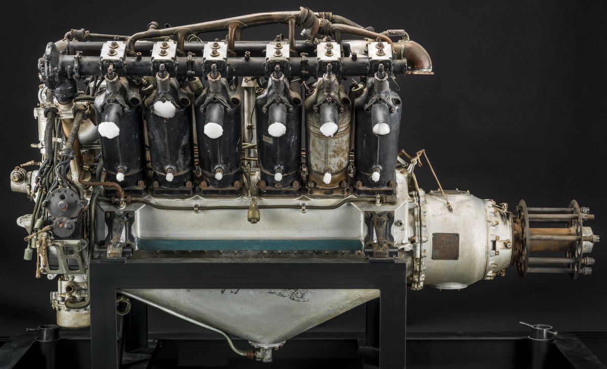
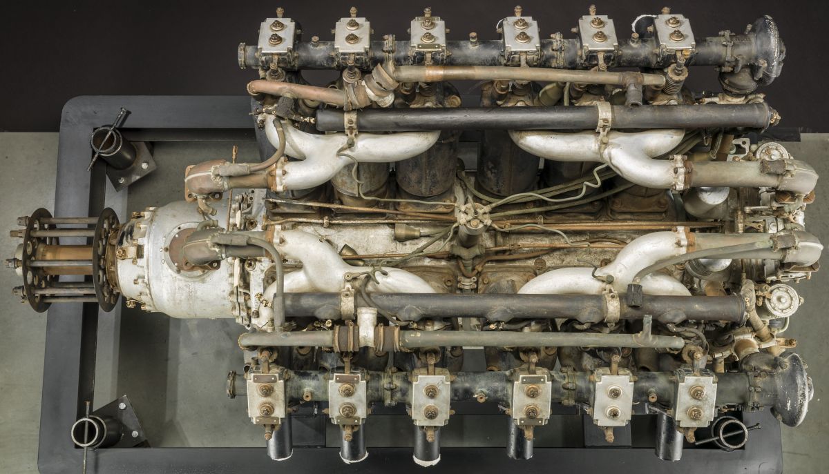
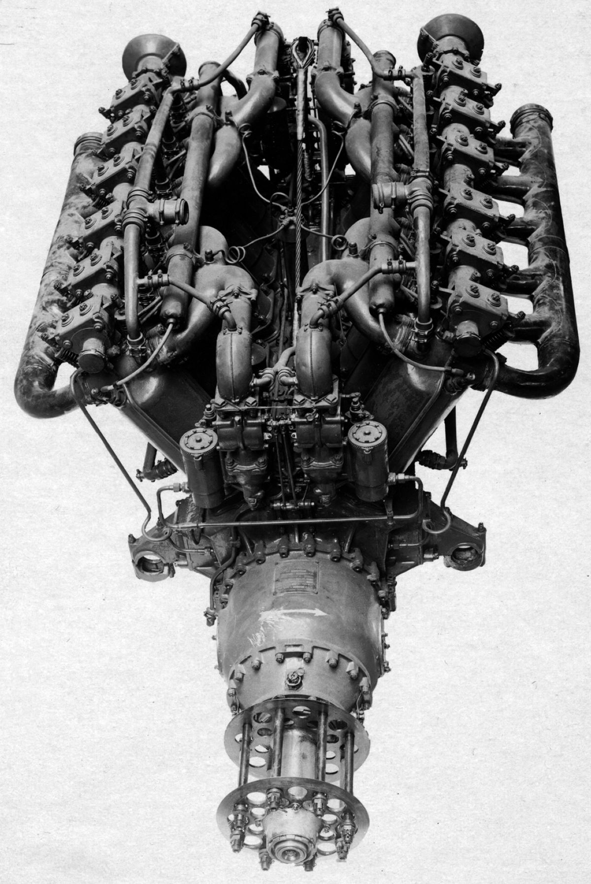
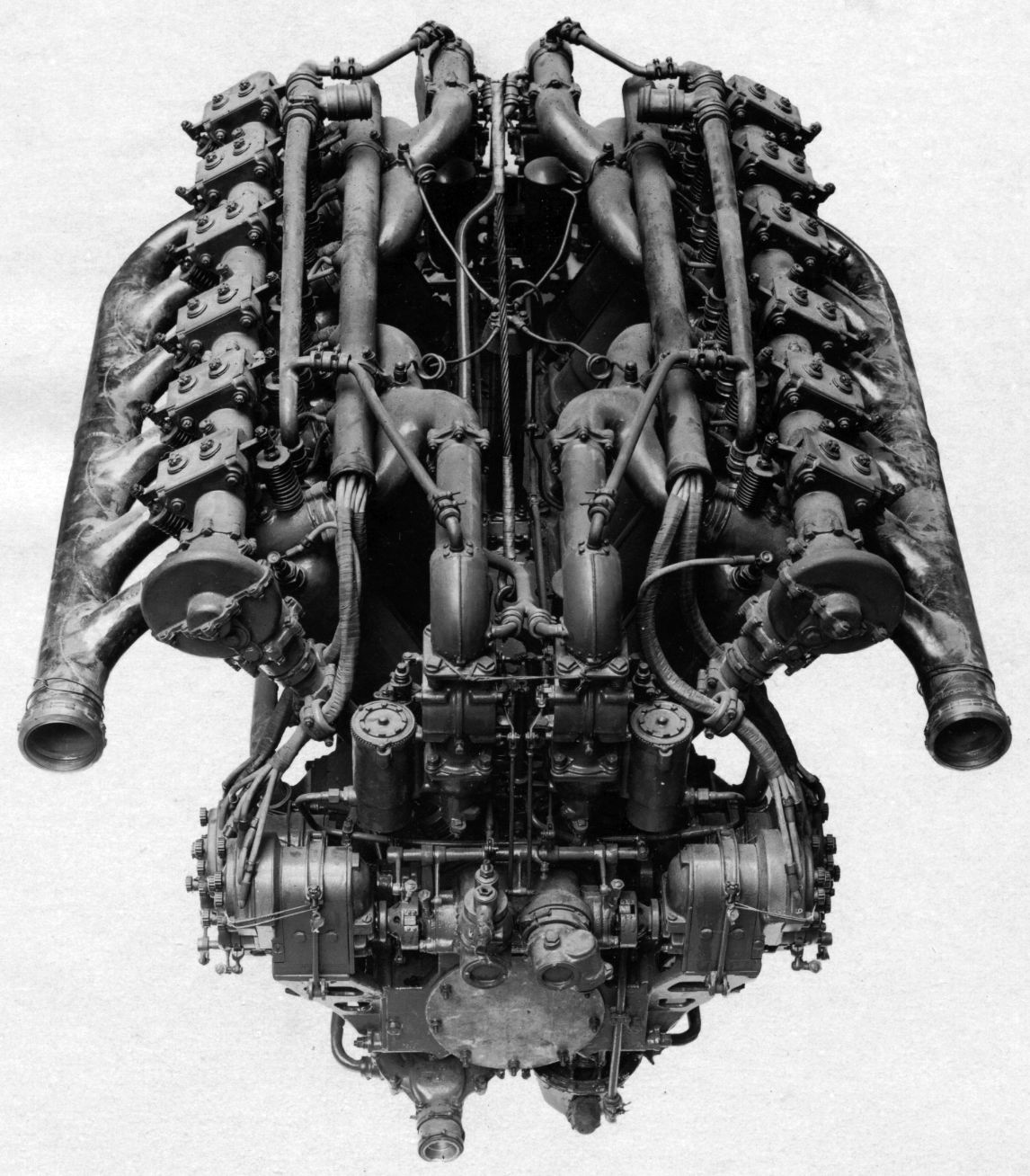
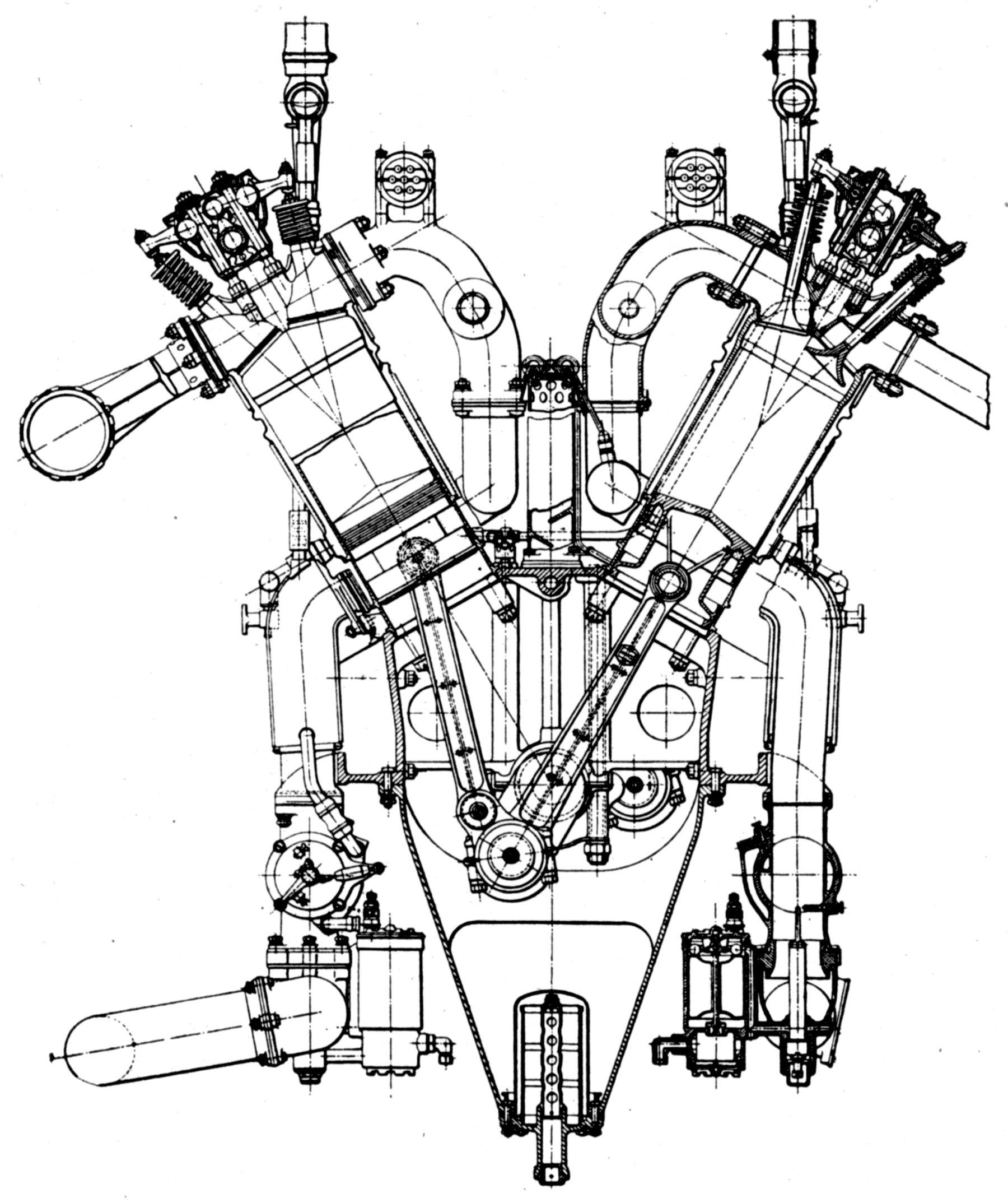
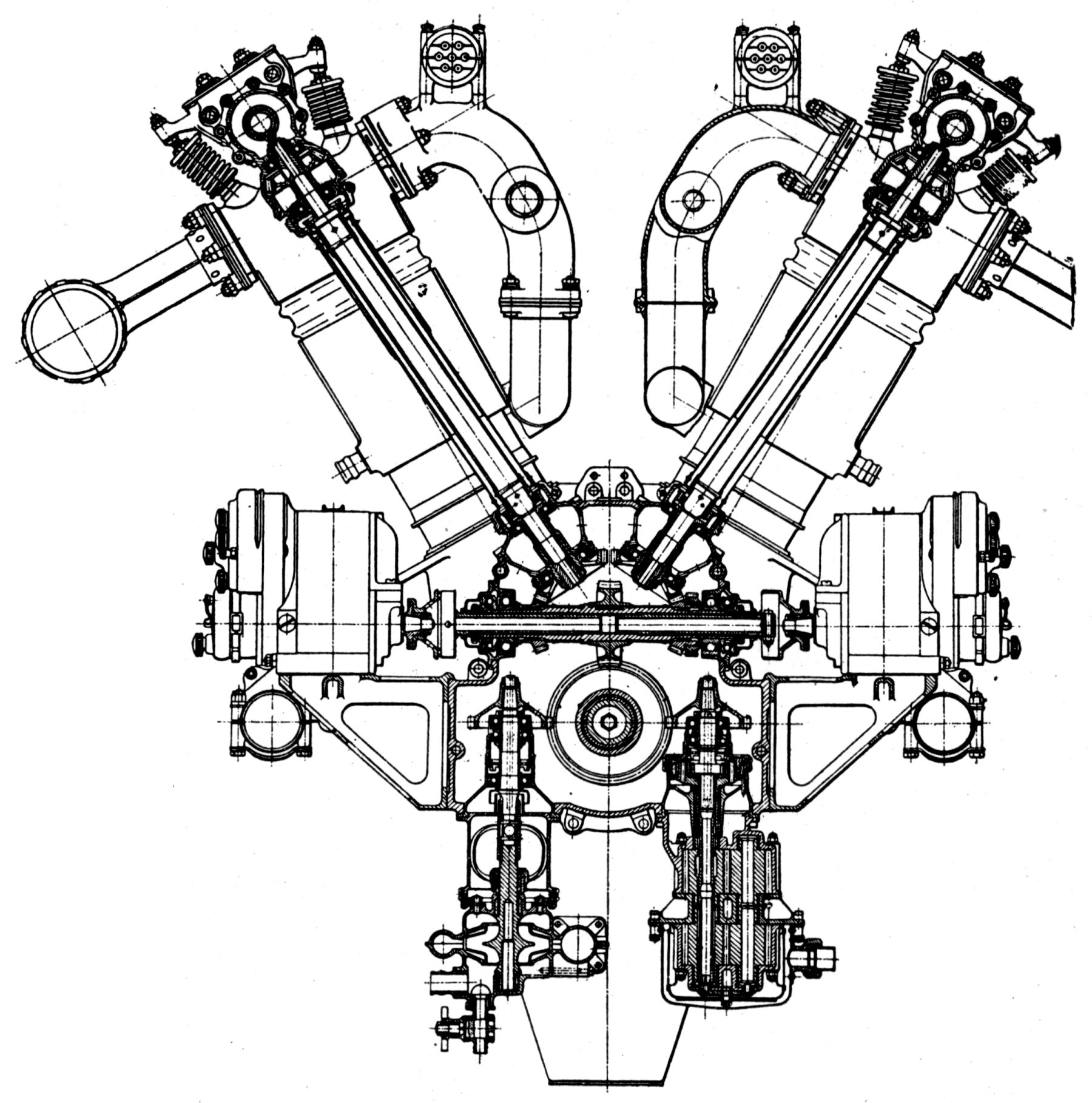
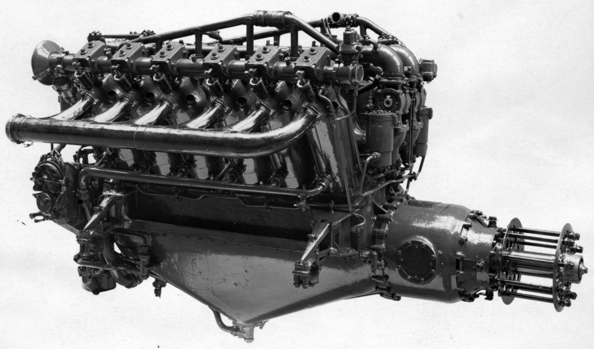
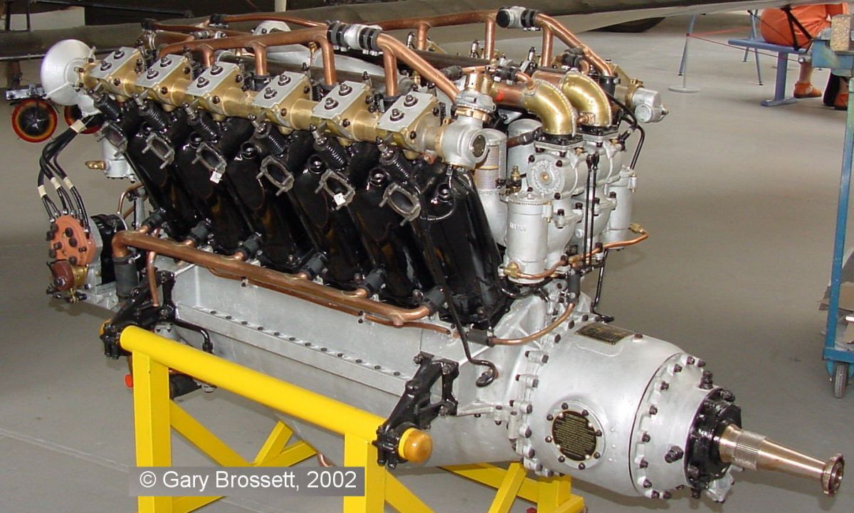
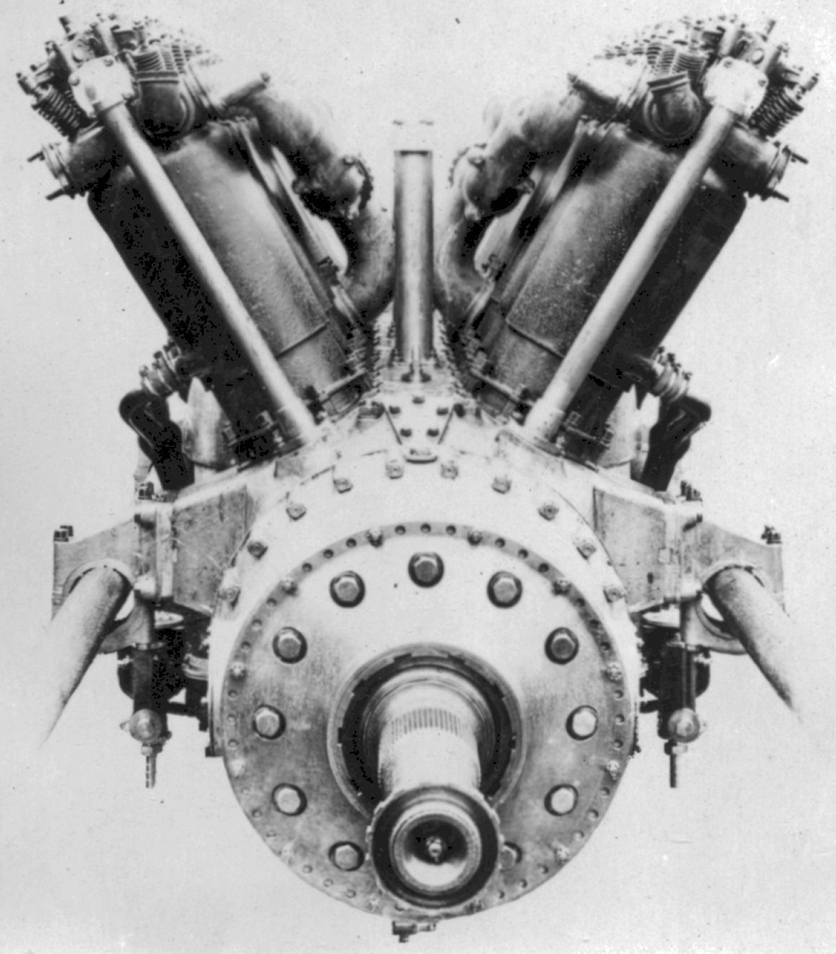
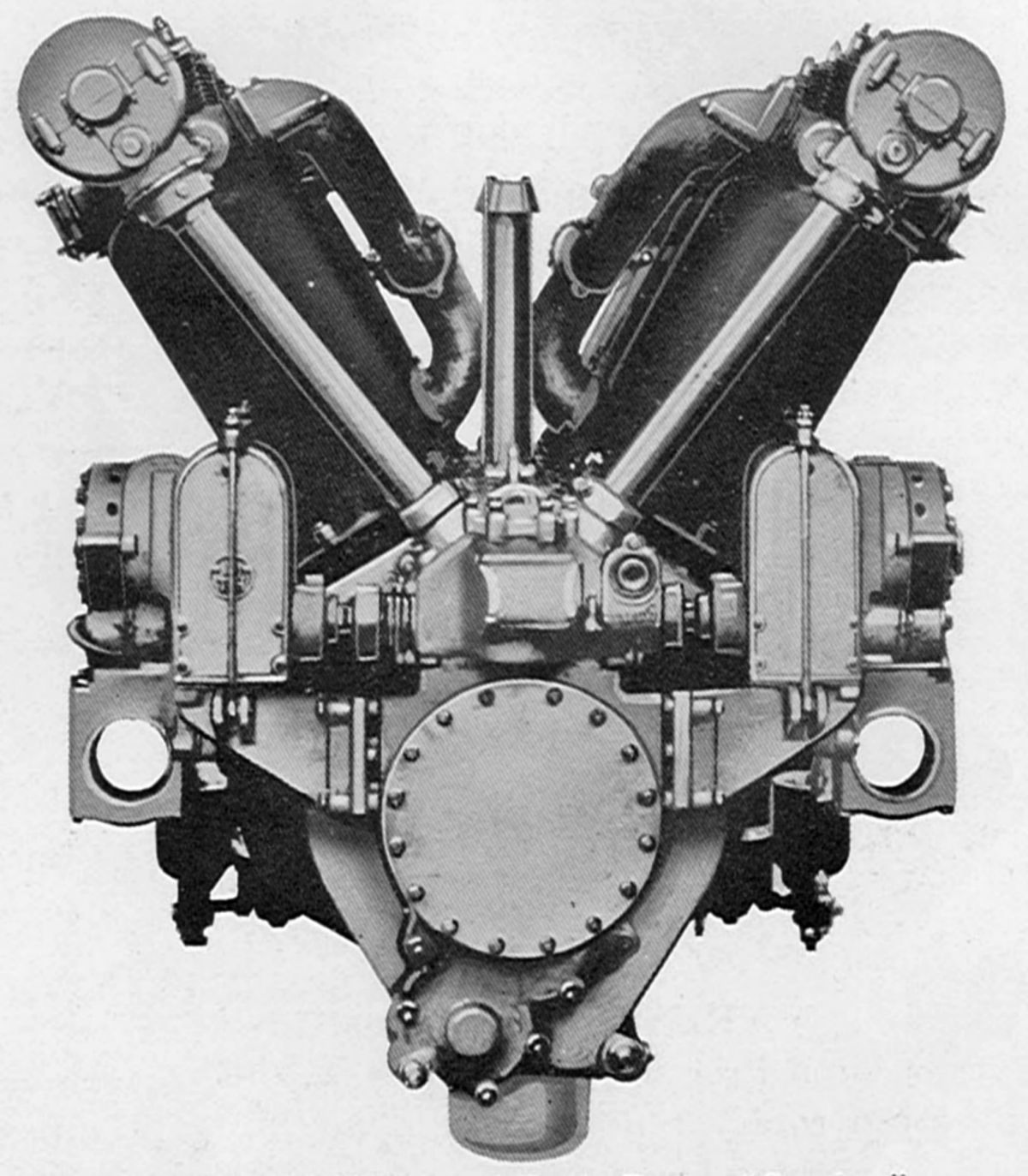
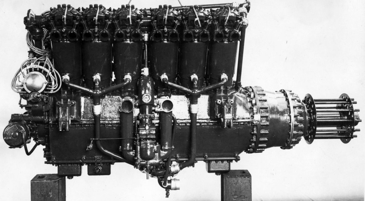
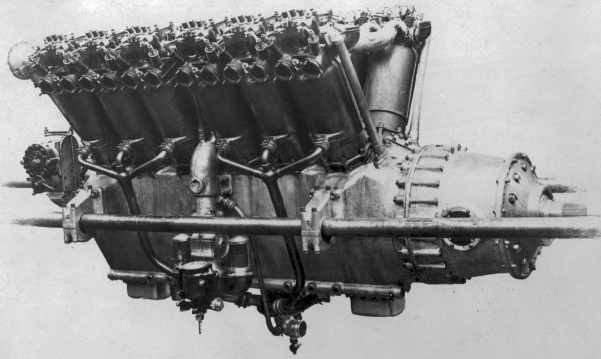
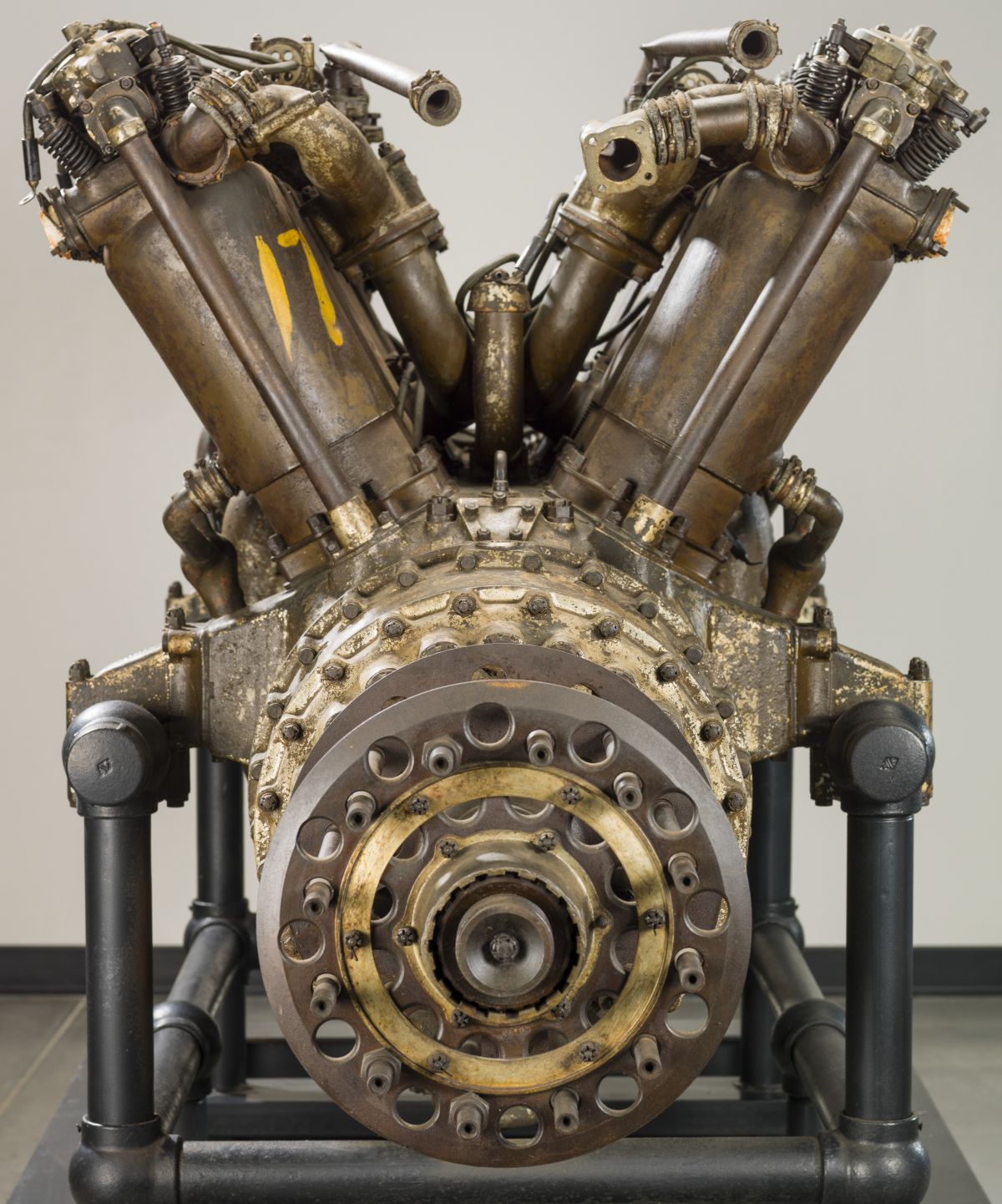
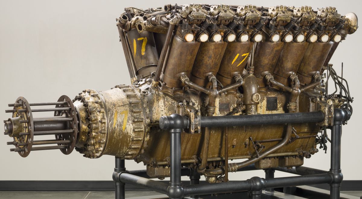
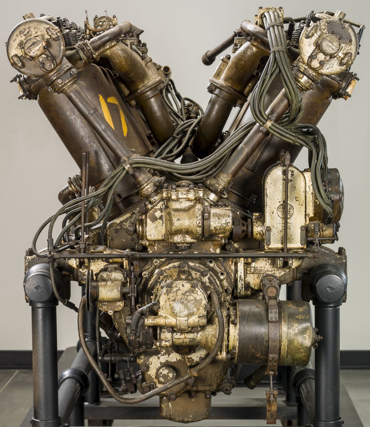
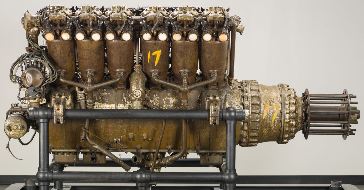
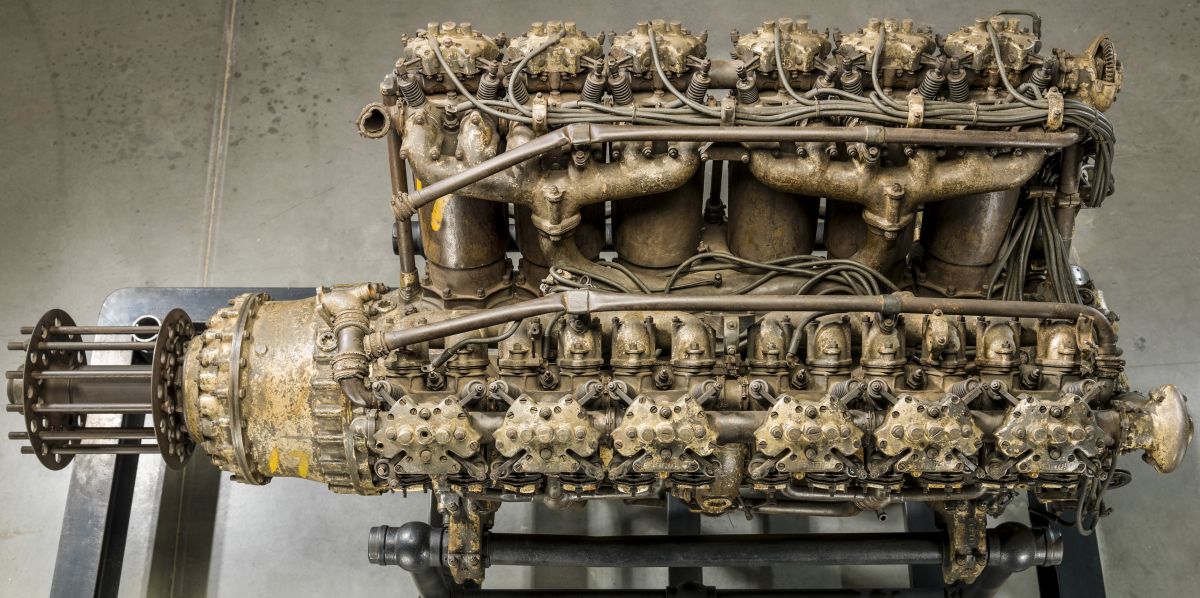
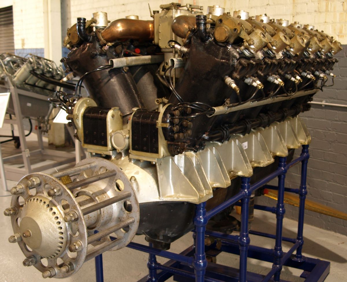
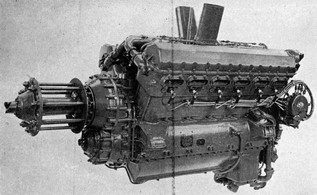
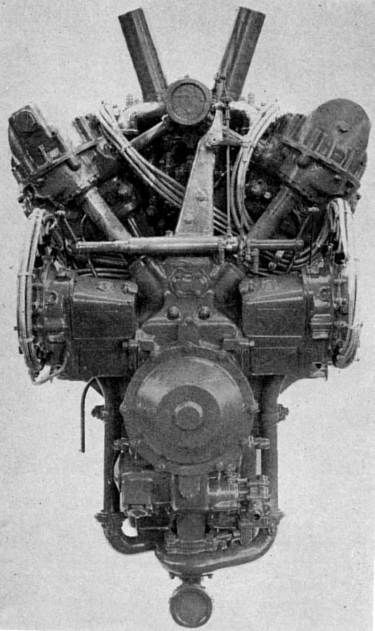
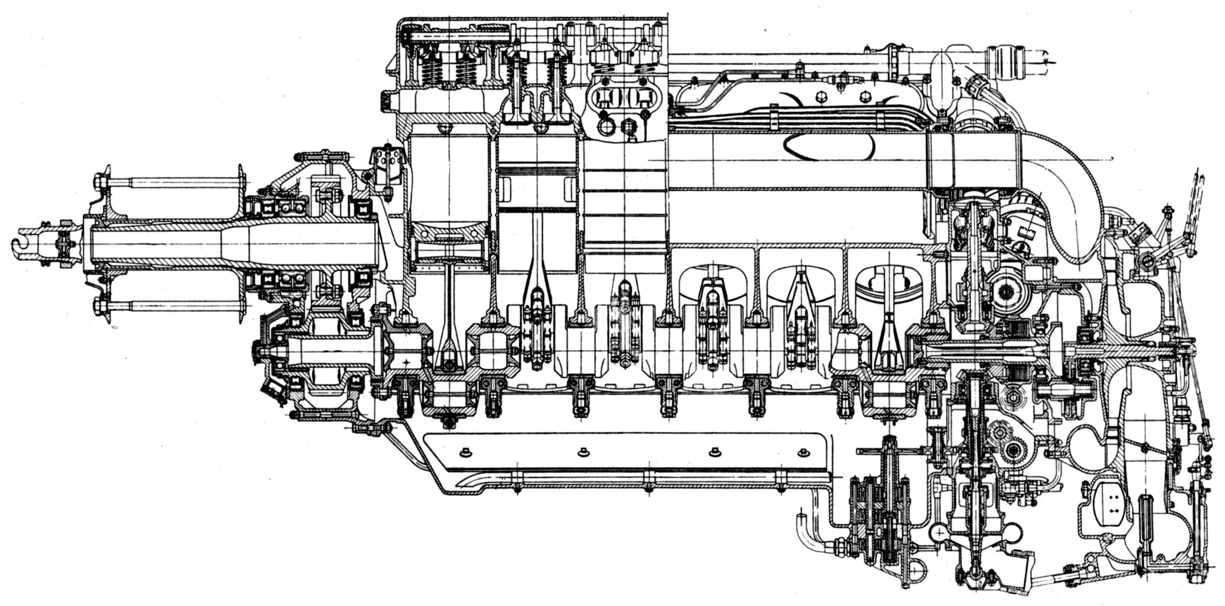
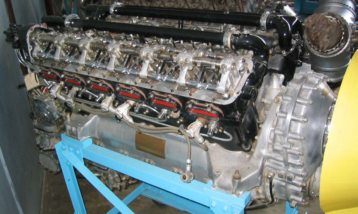
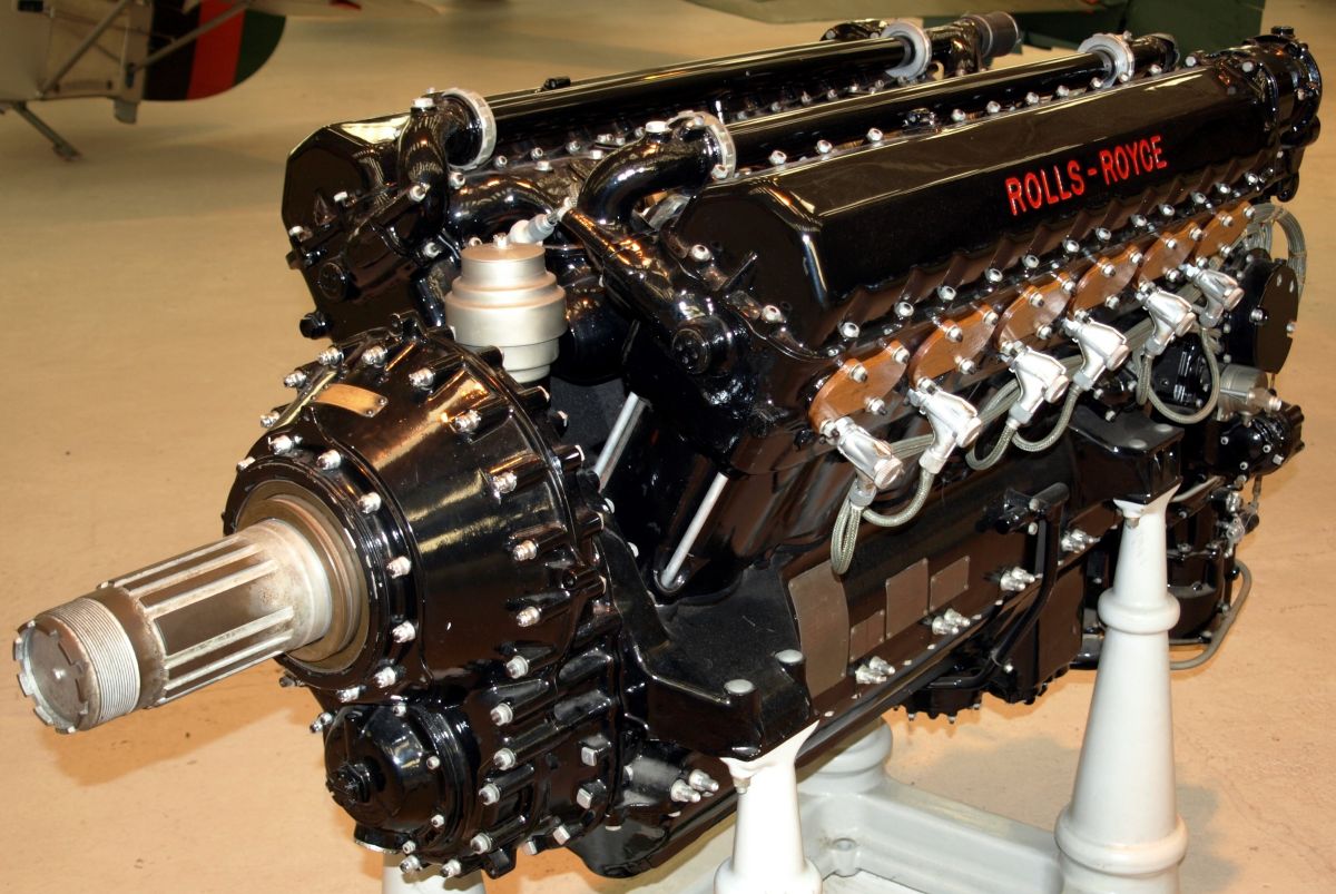
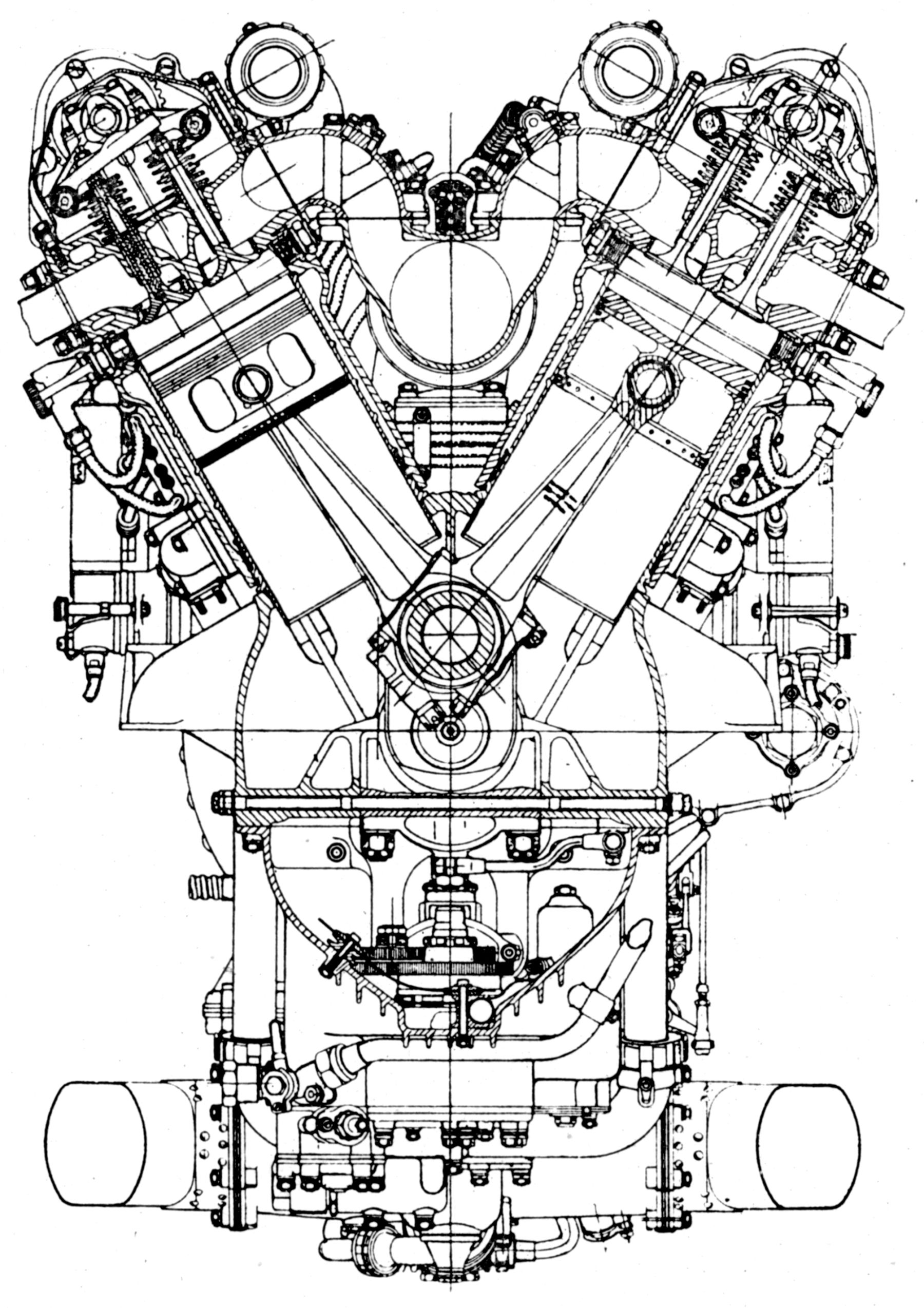
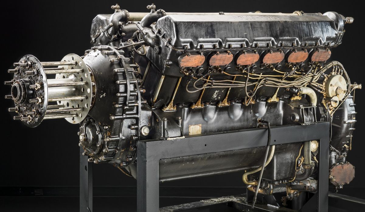
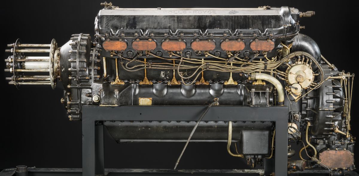
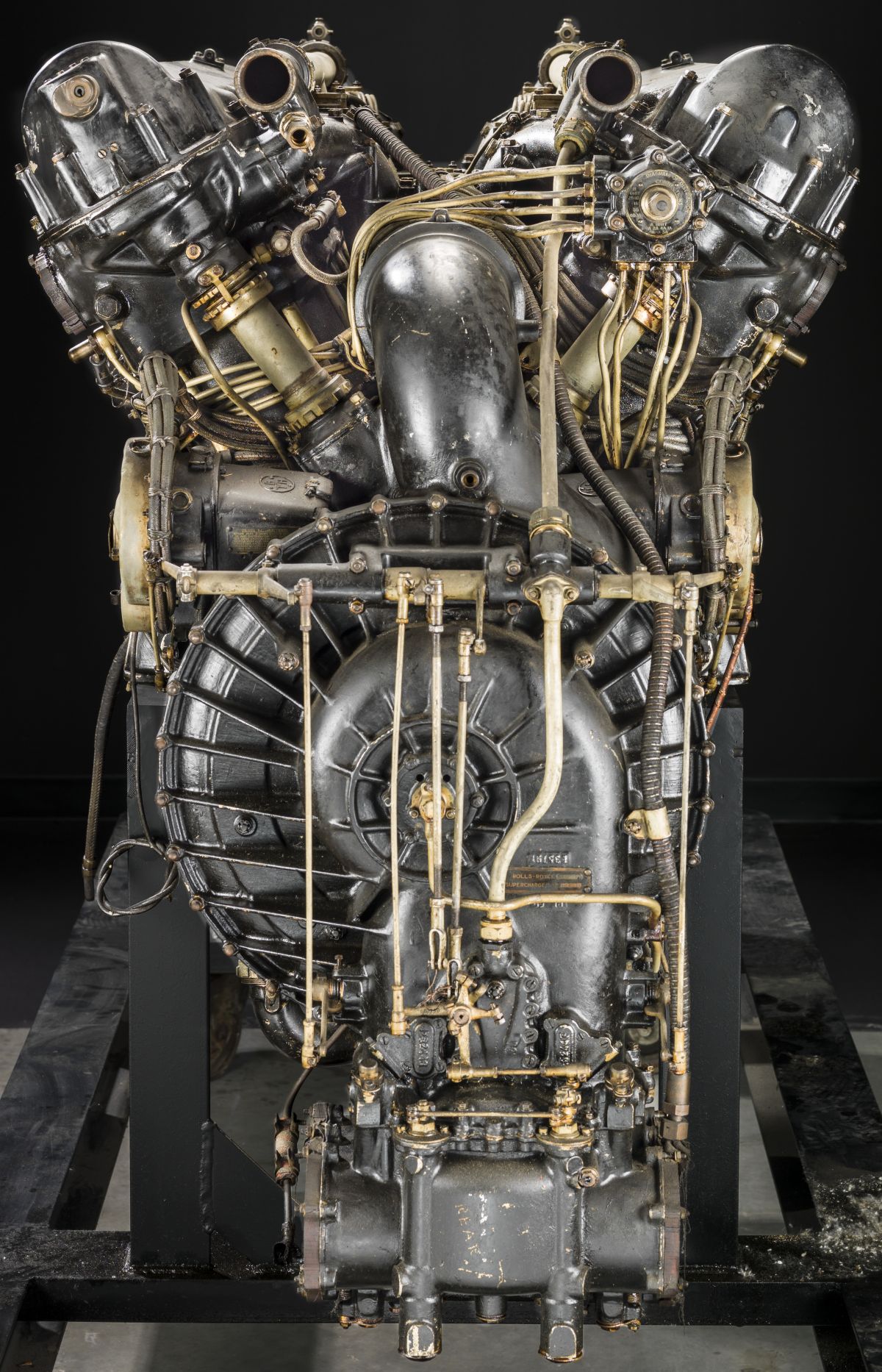
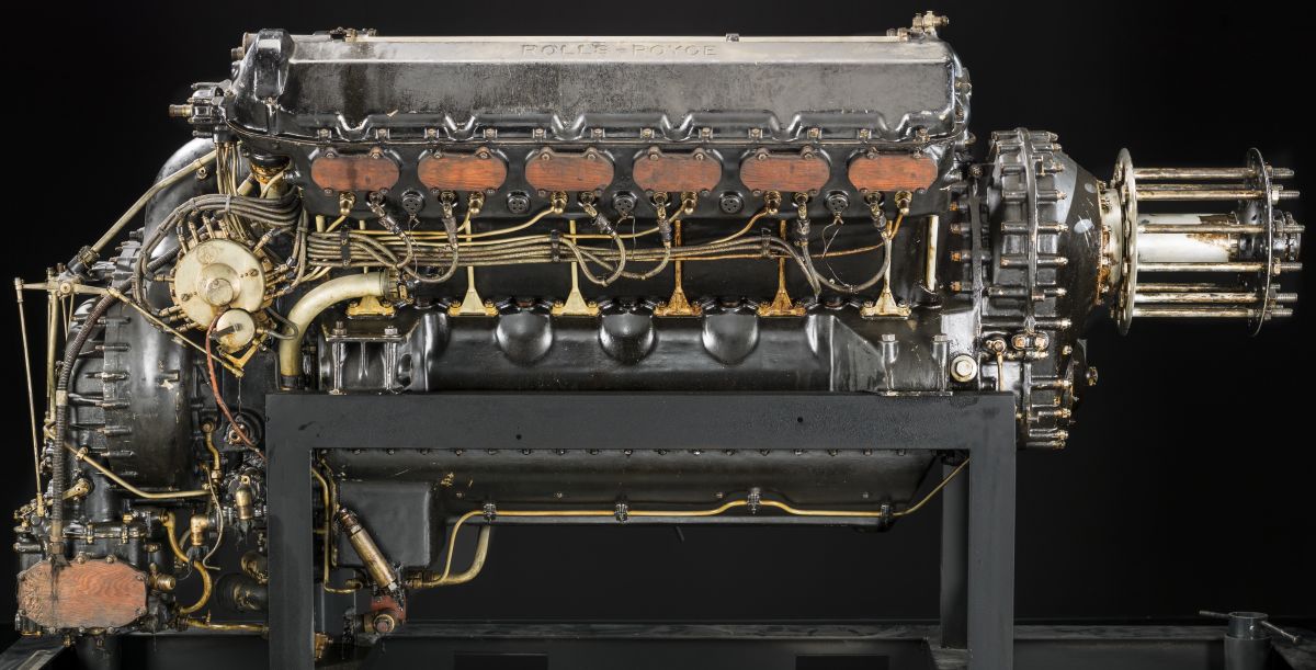
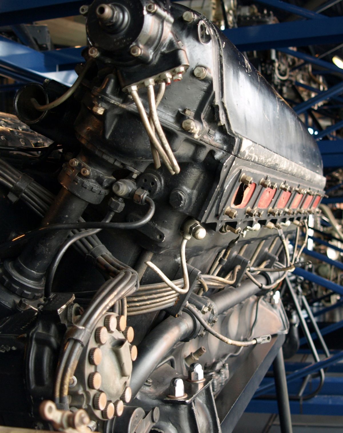
The Rolls-Royce Eagle was a water-cooled 60° V-12 with a 4.500" (114.3 mm) bore, 6.500" (165.1 mm) stroke and 1,240.54 in³ (36.14 l) displacement. The engine's water content was 3.1 gal (11.73 l), or 26 lb (11.8 kg). Length was 63.25" (1,607 mm), width 32" (813 mm), and height 39" (991 mm).
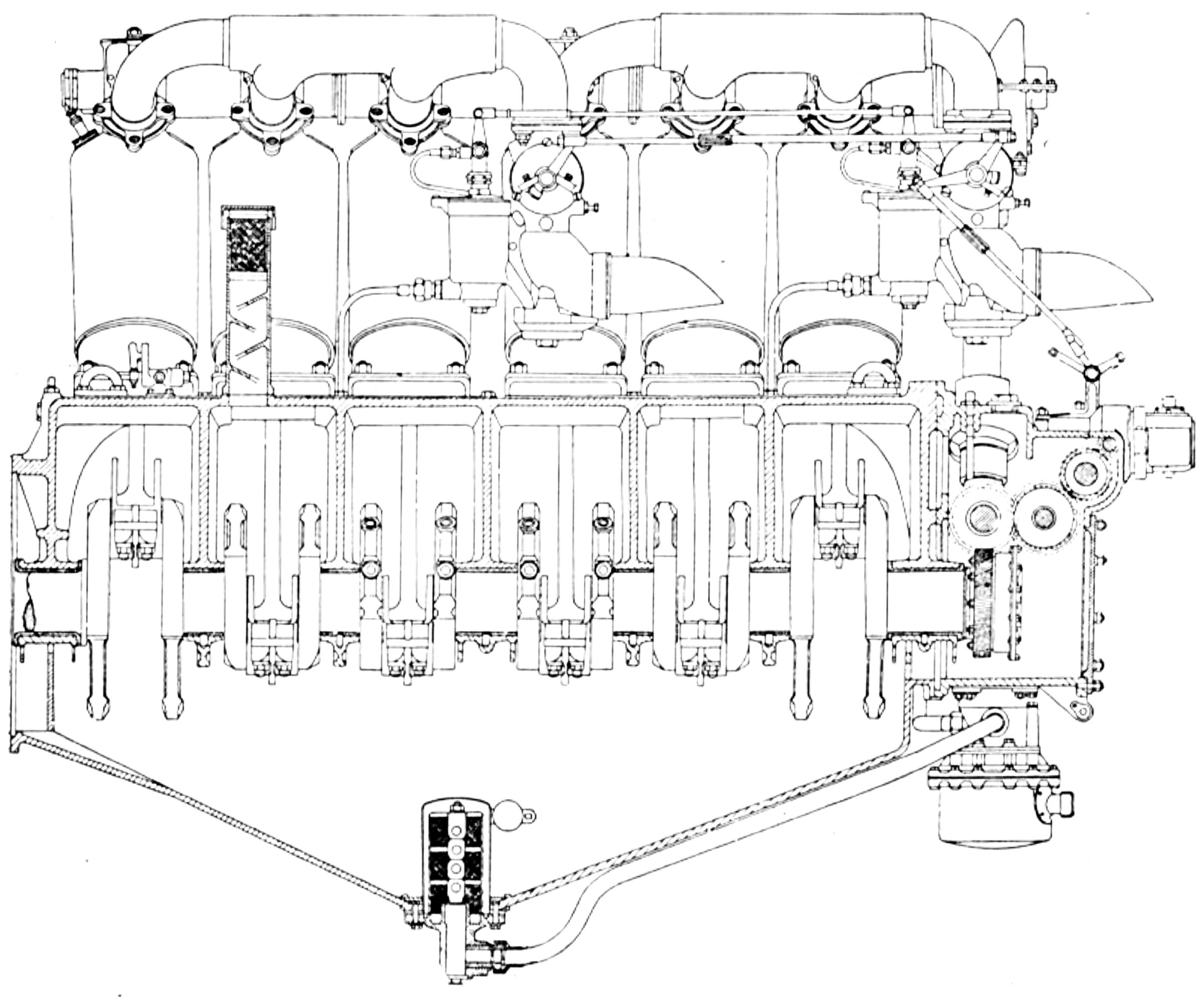
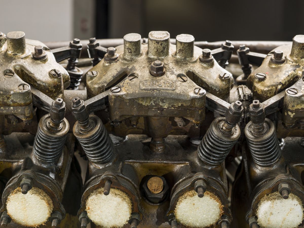
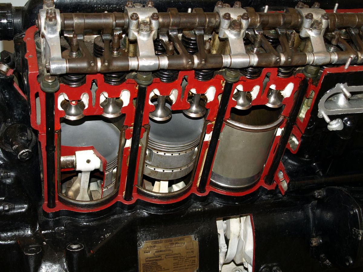
The individual cylinders, machined from steel forgings, had hemispherical combustion chambers with two inclined valves. The water jackets were made in pairs from pressed steel and welded in place. Forged steel ports were welded to the heads with the joint higher than usual to facilitate welding and prevent material accumulation near the valve seat. Interchangeable tulip inlet and exhaust valves with 2.000" (50.8 mm) clear diameters had 0.43" (10.92 mm) lift and 30° seat angles through the Eagle IV. Eagle V and later versions had 0.500" (12.7 mm) valve lift. The inlet valves opened 10° late and closed 54° late; the exhaust valves opened 58° early and closed 10° late.
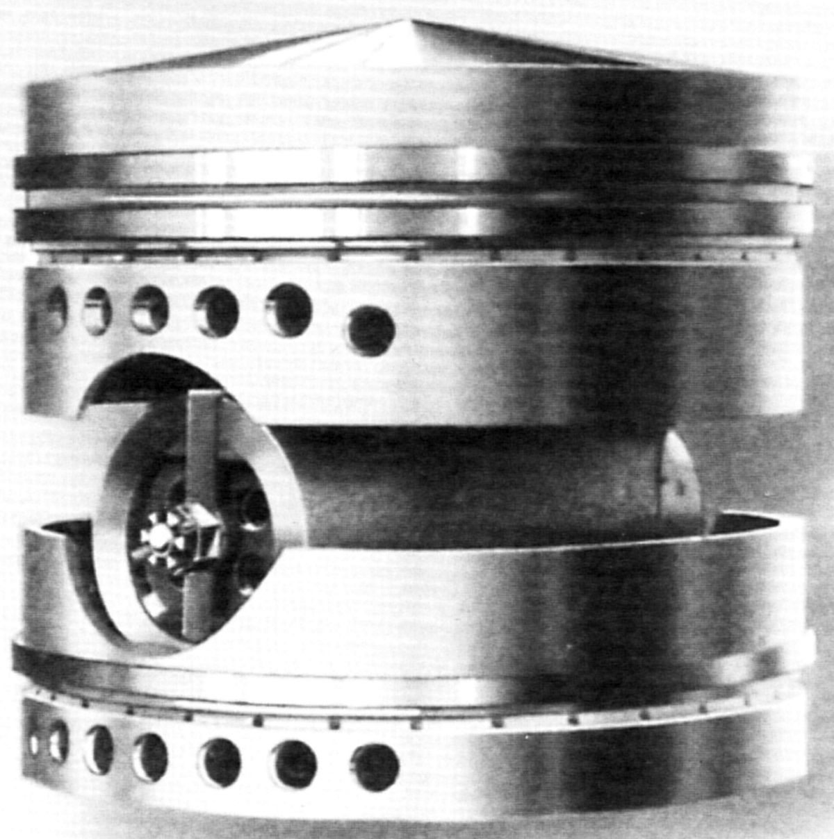
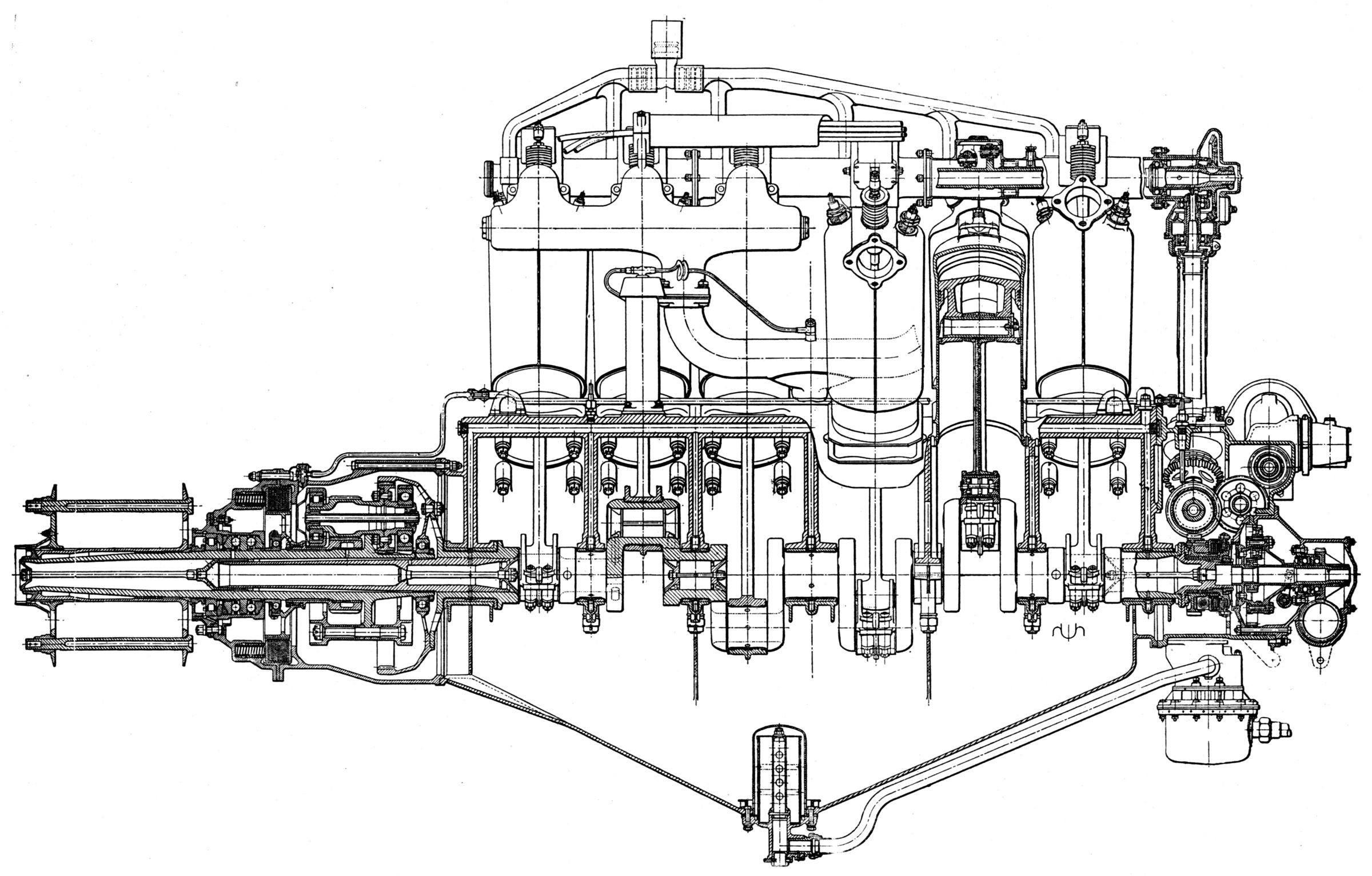
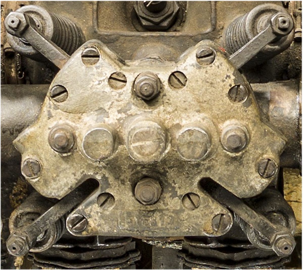
Zephyr pistons with relieved skirts carried two rings above the piston pin and one below. The piston-pin was secured in the connecting rod to prevent lateral movement and rotation, making use of an unbushed piston pin boss bearing. The six-throw crankshaft ran in seven plain bearings with individual caps. Early engines were balanced by forged steel counterweights separately attached. The crankpins had four oil holes equidistant around their circumference. A front flange attached the internal epicyclic reduction gear, which was common to most early Rolls-Royce engines. The articulated connecting rods had H-section shanks. The master rod cap joint was 38° to a line perpendicular to its axis. Both rods had clipped-on tubes that carried oil to the piston pin bearings. The babbitt master rod bearing was applied directly to the rod. The pressure-fed dry-sump lubrication drew oil from a tank via a gear pump and delivered it to the bearings past a pressure relief valve that maintained 40 psig (276 kPa). Another gear set scavenged the crankcase through a strainer located at the sump center. A piston-type air pump provided fuel feed and the cooling water was circulated by a centrifugal pump with a double-sided impeller that minimized leakage potential by requiring only one seal on the pump suction side. The overhead camshafts were driven by vertical drive shafts and bevel gears. The camshaft housings extended over six cylinders and provided slots through which the rocker arms operated. The camshaft and accessory drives originated at a coupling intended to dampen crankshaft vibrations. The aluminum alloy crankcase carried four mounting studs for each cylinder. The propeller reduction gear housing was attached by flange and screws. Each change in design involving the use of non-interchangeable parts spawned a new series designation and usually a performance gain. [Wikipedia]
|
|
|
|
| (NARA) | (AEE) | (AEE) | Zephyr Piston (RR-HT) |
Eagle I (1915), with a 4.53:1 compression ratio and 25:16 propeller reduction, was rated 243 hp at 1,600 rpm and weighed 899.5 lb (408 kg) installed. It featured six-cylinder inlet manifolds, two single 36-mm Claudel carburetors, and two magnetos to supply the single spark plug per cylinder; 104 were built.
Eagle II (1916), with a 4.53:1 compression ratio and 25:16 propeller reduction, was rated 260 hp at 1,600 rpm and weighed 906.5 lb (411.2 kg) installed. Four 36-mm Claudel carburetors were attached to three-cylinder inlet manifolds; 36 were built.
Eagle III (1917 - 1927), with a 4.9:1 compression ratio and 25:16 propeller reduction, was rated 270 hp at 1,600 rpm and weighed 906.5 lb (411.2 kg) installed. Four 36-mm Claudel carburetors were attached to three-cylinder inlet manifolds; 110 were built.
 |
| (NARA) |
Eagle IV (1916 - 1917), with a 4.9:1 compression ratio and 25:16 propeller reduction, was rated 272 hp at 1,600 rpm and weighed 904.5 lb (410.3 kg) installed. Two 38-mm Claudel duplex carburetors were used; 36 were built.
Eagle V (1916 - 1917), with a 4.9:1 compression ratio and 25:16 propeller reduction, was rated 296 hp at 1,600 rpm and weighed 909.5 lb (412.5 kg) installed. Four 38-mm Claudel simplex carburetors were used; 100 were built.
Eagle VI (1917), with a 4.9:1 compression ratio and 5:2 propeller reduction, was rated 305 hp at 1,650 rpm and weighed 959.5 lb (435.2 kg) installed. Four 38-mm Claudel carburetors were used and four magnetos supplied dual ignition; 300 were built.
Eagle VII (1917 - 1918), with a 4.9:1 compression ratio and 5:2 propeller reduction, was rated 305 hp at 1,650 rpm and weighed 959.5 lb (435.2 kg) installed. Four 38-mm Claudel carburetors were used and four magnetos supplied dual ignition; 200 were built.
Eagle VIII (1917 - 1922), with a 5.3:1 compression ratio and 5:2 propeller reduction, was rated 360 hp at 1,800 rpm and weighed 949.5 lb (430.7 kg) installed. Four 42-mm Claudel carburetors were fitted to new three-cylinder intake manifolds. A few special Eagle VIII engines were built using camshafts with high lift cams produced over 400 hp; 3,302 were built. [Ratings from Taulbut, 251 – 252. Initial horsepower values are given.]
 |
 |
 |
 |
 |
 |
 |
 |
| (Dane A. Penland, CC0, via Wikimedia Commons) | (NARA) | ||||||
 |
 |
 |
 |
| (Wiki) | (A39) | (AEE) | |
The Eagle IX (1922 ‑ 1928), last in the series, was rated 360 hp at 1,800 rpm and developed 390 hp at 2,000 rpm. Compression ratio was 5.22:1. Fuel and oil consumptions were 0.51 and 0.027 lb/hp/hr. Dry weight, including the propeller hub and exhaust pipes, was 965 lb (438 kg). Important alterations, as compared to the Eagle VIII, included two new Rolls-Royce-Claudel-Hobson carburetors located at the sides in a position lower than before; this produced a better fuel head pressure with gravity-fed systems. The air intakes were arranged to extend outside the engine cowling and reduce fire hazard. These carburetors included a greatly simplified mixture control. A strengthened crankshaft and improved camshaft drive, new corrugated water jackets, water pump improvements, a friction clutch in the epicyclic reduction gear to prevent overloading were also included. Four six-cylinder Watford magnetos furnished dual ignition; 373 were built.
 |
 |
 |
 |
 |
 |
 |
| (Wikimedia) | (NARA) | (Wikimedia) | (NARA) | (Gary Brossett) | (NARA) | |
The Falcon, first delivered in September 1916, was a water-cooled 60° V-12 similar to the Eagle. It had a 4.00" (101.6 mm) bore, 5.750" (146.1 mm) stroke, 867.08 in³ (14.21 l) displacement and 95/56 epicyclic reduction gear ratio. Its water content was 2.5 gal (9.5 l), or 21 lb (9.5 kg). All Falcons were equipped with two magnetos and three-cylinder intake manifolds.
Falcon I (1916 – 1917), with a 5.15:1 compression ratio, was rated 228 hp at 2,000 rpm and weighed 721 lb (327 kg) installed. Two Claudel 34-mm duplex carburetors were used; 250 were built.
Falcon II (1917), with a 5.15:1 (later 5.3:1) compression ratio, was rated 255 hp at 2,000 rpm and weighed 722 lb (327.5 kg). Two Claudel 34-mm duplex carburetors were used; 250 were built.
Falcon III (1917 – 1927), with a 5.3:1 compression ratio, were rated 270 hp at 2,000 rpm and weighed 737 lb (334.3 kg). Four single 38-mm Rolls-Royce Claudel-Hobson carburetors and new larger three-cylinder inlet manifolds were used; 1,685 were built. [Ratings from Taulbut, 253 – 254. Final horsepower values are given.][A39, Wikipedia]
 |
 |
| (Wikimedia) | (NMUSAF) |
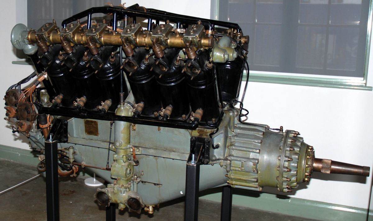
The Rolls-Royce Hawk (1915 – 1918), was a direct-drive water-cooled vertical six with a 4.000" (101.6 mm) bore, 6.000" (152.4 mm) stroke, 452.39 in³ (7.41 l) displacement and 5.0:1 compression ratio. It was 46.75" (1,187 mm) long, 23" (584 mm) wide and 28.75" (730 mm) high. Individual 2-valve steel cylinders had one spark plug supplied by a single magneto. Once Rolls-Royce completed and tested the design, Brazil Straker built 204 under license. The Hawk I, using two single-barrel Claudel 28-mm carburetors, each separately attached to a three-cylinder intake manifolds, was rated 91 hp at 1,500 rpm and weighed 406.5 lb (184.4 kg) installed. The Hawk II, with a single two-barrel carburetor, was rated 105 hp at 1,500 rpm and weighed 420 lb (190.5 kg) installed. [Ratings from Taulbut, 253 – 254. Final horsepower values are given.] [A39, Wikipedia]
 |
 |
 |
 |
| (NARA) | |||
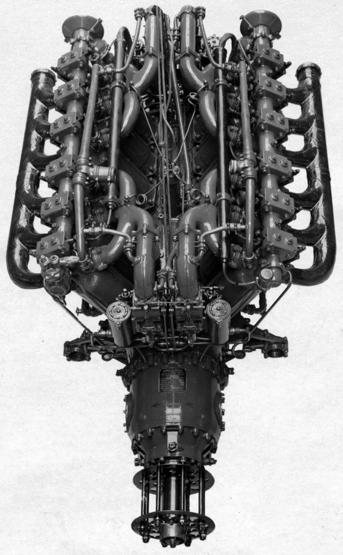
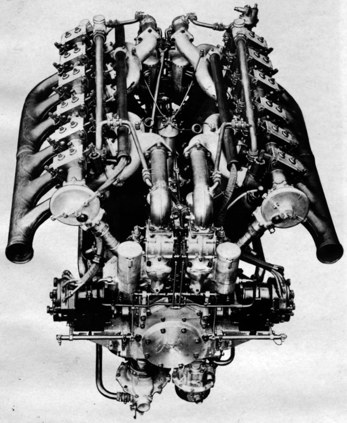
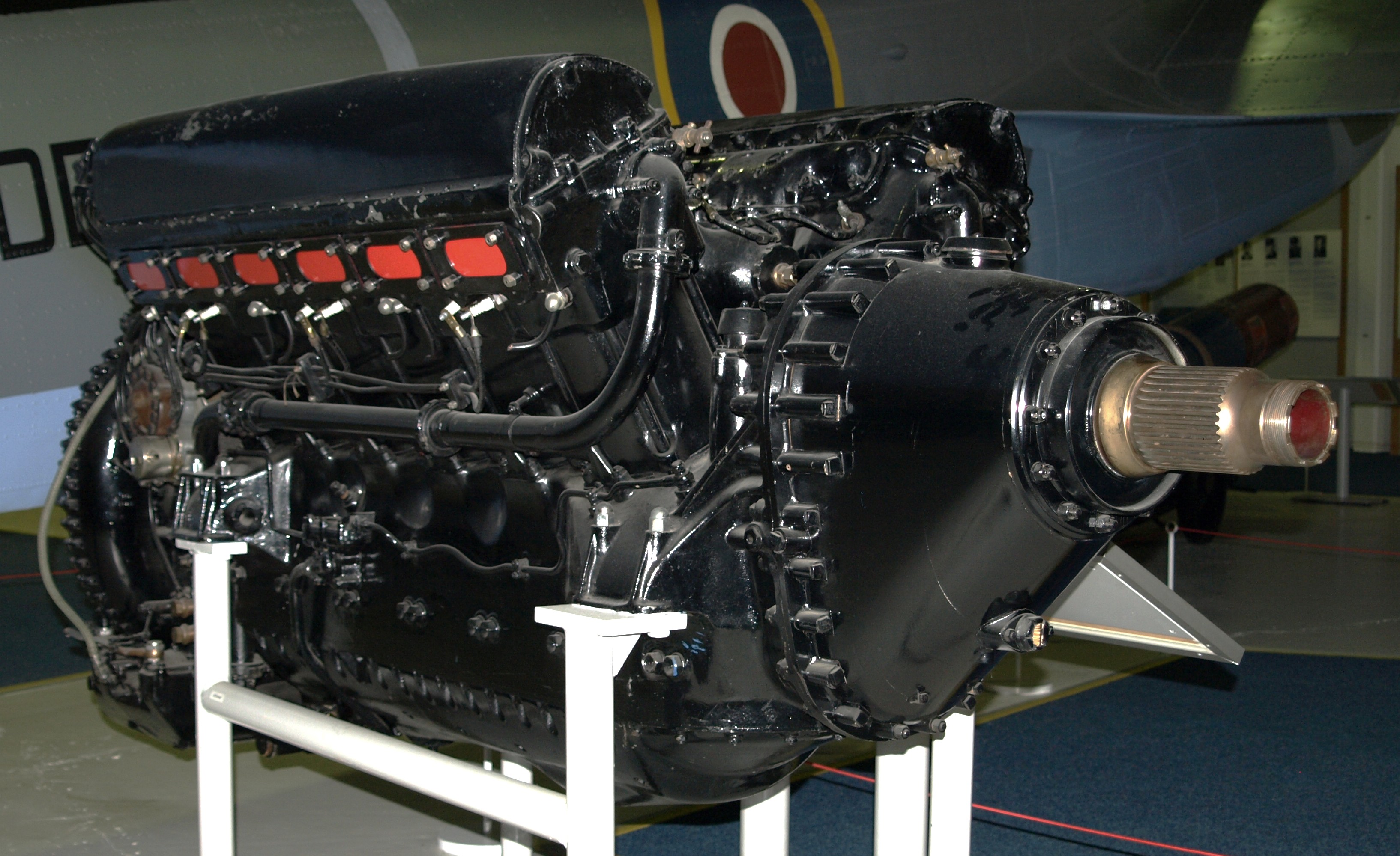
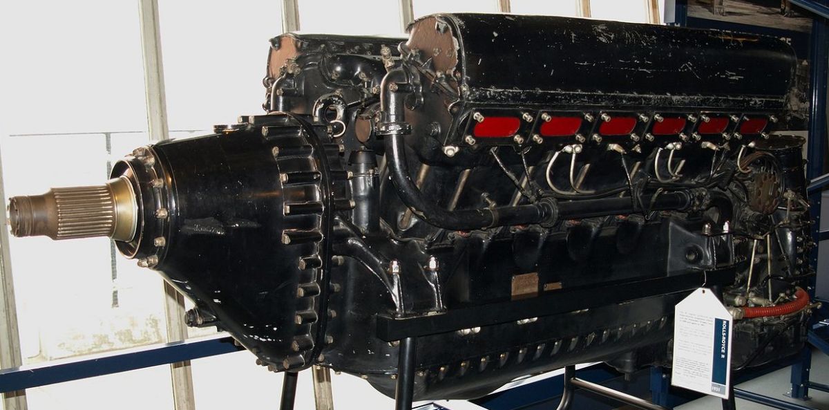
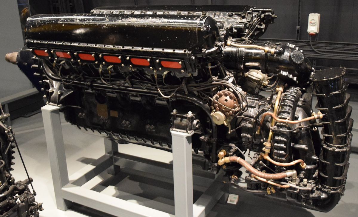
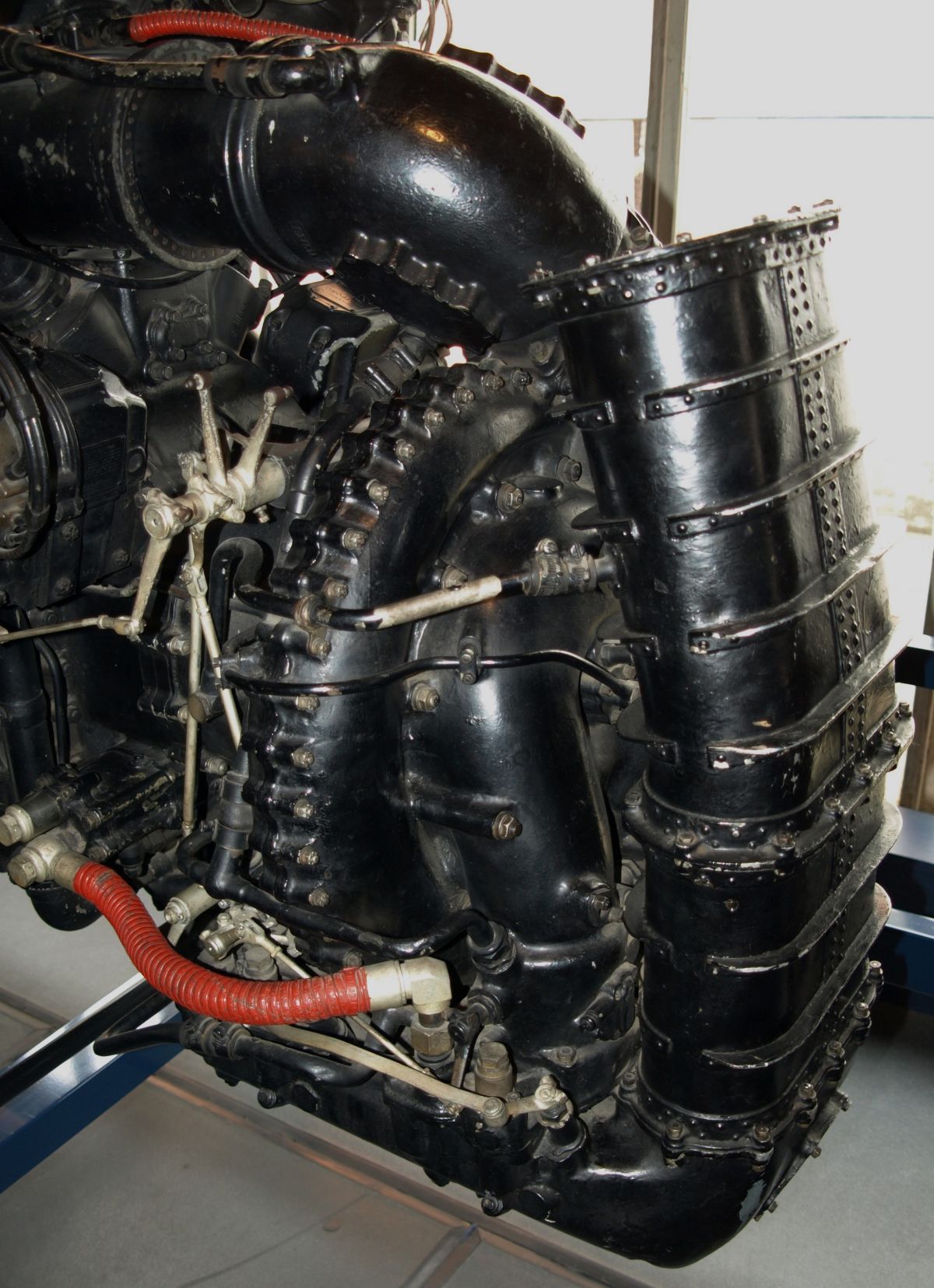
The Rolls-Royce Condor I (1920 – 1921), developed for long-range bombers, was a geared liquid-cooled 60° V-12 with a 5.500" (139.7 mm) bore, 7.500" (190.5 mm) stroke, 2138.25 in³ (35.040 l) displacement and 5.0:1 compression ratio that was initially rated 610 hp at 1,750 rpm and 656 hp at 2,000 hp. Dry weight for the 3:2 gear ratio was 1,300 lb (589.7 kg); for the 1.8051:1 ratio it was 1,440 lb (653.2 kg). Five gallons (19 l) of water weighing 42 lb (19 kg) were carried in the jackets and plumbing. The Condor I was 71" (1,803 mm) long, 33" (838 mm) wide and , and 42" high; 72 were built.
The Condor Ia (1921), also designated Condor II, followed the Condor I, but only 34 were built. Several small design changes, including a compression ratio increase to 5.17:1 raised the output to 650 hp at l,900 rpm.
 |
 |
 |
 |
 |
 |
 |
| (Wikimedia) | ||||||
 |
| (Wikimedia) |
The Condor III (1923 – 1927), weighed considerably less than the Condor Ia but retained its output with a 6.5:1 compression ratio. A spur reduction gears was carried in a housing bolted to the crankcase front, the first time Rolls-Royce used this scheme. The pinion was on a short shaft supported by two roller bearings. The shaft was driven via an external spline that mated with an internal spline bolted to the crankshaft front. The driven gear was attached to a large diameter shaft with a standard metal propeller mounting flange; 196 were built.
The Condor IIIA, (1925), with a 650 - 665 hp output, incorporated an improved main bearing design and material.
The Condor IIIB (1930), with a 2.0964:1 reduction gear, re-designed crankcase and crankshaft, was rated 650 hp.
The Condor IV (1925), was a direct-drive 750 hp version with modified engine mounting; 13 were built.
The Condor IVA (1927), was rated 750 hp; 9 were built.
The Condor V (1925), was a Condor IIIA with two-stage turbosupercharger. One was built but not flown.
The Condor VII, was direct-drive Condor IIIA; 2 were built.
Separate Condor cylinders were machined from steel forgings, valve ports were welded in place and pressed-steel jackets were welded on to complete the assembly. The cylinders were galvanized to protect them from corrosion. Tubular steel housings for the overhead camshafts had brazed-on steel attachment brackets. Each camshaft ran on six split aluminum bearings and two bushings located at each housing ends. There were three cams for each cylinder; the central cam operated two inlet rocker arms and the two adjacent cams one exhaust rocker arm each. The axes of the four valves converged toward the cylinder axis, making them normal to the hemispherical combustion chamber. Correct valve stem action was obtained by interposing, between the cams and rocker arms, cylindrical tappets working in vertical guides in the camshaft housing boxes. The tappets were slotted at the approximate rocker arm angle with the rocker arm end projecting into the slot and being driven from the hard face at the slot bottom.
Rolls-Royce Zephyr aluminum alloy pistons were fitted with two compression rings and an oil scraper rings above the piston pin and another oil scraper ring below the piston pin. Fork-and-blade connecting rods with H-section shanks were used. The six-throw crankshaft ran in seven plain bearings. The two end bearings were carried directly in the crankcase, while the five intermediate bearings were carried in the crankcase lower half by duralumin bridges, each held by a cross bolt pair These bridges also carried two long vertical bolts that extended through the crankcase top, further reinforcing the end bearings.
Auxiliary drives were taken from a spur gear located at the crankshaft rear, where a friction-dampened spring drive isolated crankshaft torsional vibrations. Above and parallel to the crankshaft, a short shaft driven by this pinion drove a magneto cross shaft. Inclined magneto shafts also drove the overhead camshafts. Between the camshaft drives was a vertical shaft operating a gas distributor for starting. Fuel, oil, and water pumps were arranged in a detachable unit located on the crankcase bottom. Two special Rolls-Royce-built Claudel-Hobson duplex carburetors supplied the mixture. Two gear-type oil pumps comprised a pressure and a scavenging pump.
The Condor IIIa compression ratio was 5.3:1, and the weight (including reduction gears) was 1,310 lb (594 kg). The gear ratio for military use was 2.0964:1 and for commercial purposes it was 1.7182:1. The rated output military output was 650 hp at 1,900 rpm and the maximum was 700 hp at 2,100 rpm. Commercial ratings were 600 hp at 1,700 rpm and 670 hp at 1,900 rpm. Length was 69.325" (1,761 mm), width was 30.525" (775 mm) and height was 42" (1,067 mm). Some Condor IIIa engines were fitted with superchargers.
The Condor IV was a direct-drive engine, but otherwise followed the Condor IIIa design. Engine supports were cast integral with the crankcase to replace the ball-joint front-end mounting and sprung link rear-end mounting employed on previous Condors. The Condor IV dry weight was 1250 lb (567 kg).
The Condor Diesel was a 1932 Rolls-Royce experiment that converted a Condor to operate as a compression ignition engine. It was strengthened as required to pass a 50-hr test with a 12.5:1 compression ratio and 800 psi maximum combustion pressure. It developed 480 – 500 hp at 1,900 rpm. With starter and accessories, but without propeller hub, it weighed 1,504 lb (682 kg). [A39, Wikipedia]
 |
 |
 |
| (AEE) | ||
The F-X (1926), first of the F-series engines, was a water-cooled 60° V-12 with a 5.000" (127 mm) bore, 5.500" (139.7 mm) stroke and 1,295.91 in³ (21.24 l) displacement. It was rated 460 hp at 2,100, produced 490 hp at 2,350 rpm and weighed 760 lb (344.7 kg). Each six-cylinder block was cast from a special aluminum alloy to accommodate wet cylinder liners, along with integral cylinder heads and induction passages. Two inlet and two exhaust valve seats and guides were then inserted. Long studs passing through the blocks captured the flanged steel cylinder liners. A single overhead camshaft in each block operated the valves through individual rocker arms. The valve mechanism was enclosed and lubricated by a low-pressure oil feed. The inlet valves were placed toward the block inner sides where two duplex carburetors fed three cylinders each. The F-X was originally a direct-drive engine, but the engine front was arranged so that the propeller shaft was carried in a housing bolted to the crankcase front allowing a spur-type reduction gear to be substituted. The crankshaft ran on seven plain bearings, the fork-and-blade connecting rods had H-section shanks, and the pistons were aluminum alloy forgings. One pressure and two scavenging gear pumps were located in the oil sump. One scavenging pump transferred oil from the engine front to a well at its rear where the other scavenging pump conveyed all drainage oil to an outside supply tank. High pressure oil was delivered to the journal and crankpin bearings via a pressure pump and oil pressure relief valves. A two-outlet volute centrifugal pump circulated cooling water to each cylinder bank. The engine was equipped with a gear-type gasoline pump and a gun drive. Two 12-cylinder magnetos mounted crosswise at the engine rear supplied dual ignition.
 |
 |
 |
 |
| Kestrel VI (Wikimedia) | Kestrel XVI (Wikimedia) | Kestrel IV (A39) | |
The F-XI, or Kestrel, was a later F-type Rolls-Royce engine series fitted with 1.5823:1 spur propeller reduction gears. The F-XI-A, or Kestrel A, with a 6.0:1 compression ratio, was rated 490 hp at 2,250 rpm. The F-XI-B, or Kestrel B, with a 7.0:1 compression ratio, was rated 480 hp at 2,250 rpm Both engines could be operated up to 2,500 rpm. Dry weight was 865 lb (392.4 kg), length was 71.5" (1,816 mm), width was 24.4" (620 mm), and height was 37.5" (953 mm).
The F-XII-A, with a 6.0:1 compression ratio, was rated 490 hp at 2,500 rpm. The F-XII-B, with a 7.0:1 compression ratio, was rated 480 hp at 2,500 rpm. Both engines had a 1.8083:1 reduction gear ratio, weighed 865 lb (392.4 kg), were 66.442" (1,688 mm) long, 24.4" (620 mm) wide and 34.517" (877 mm) high. Some of these engines also had engine-driven centrifugal superchargers.
The Kestrel IV, V and VI engines, also known as type S, were fully supercharged and rated 600 hp at 2,500 rpm and 11,000 ft (3,354 m). They produced 640 hp at 2,900 rpm and 14,000 ft (4,267 m). The superchargers ran at 8.8 times crankshaft speed, giving a 1.5 psi boost; fuel was 87 octane. Dry weight was 955 lb (433.2 kg), length was 72.35" (1,838 mm), width was 24.4" (620 mm), and height was 35.6" (904 mm).
The Kestrel VII, VIII and IX engines, also known as type NIS, were identical to the IV, V and VI except that the supercharger ran at 6.92 times crankshaft speed, giving a 2.625 psi boost. Normal rating was 675 hp at 2,500 and 3000 ft (914 m), and maximum rating was 730 hp at 2,900 rpm and 5000 ft (1,524 m).
The Kestrel X, XI and XII engines, also known as type B, were not supercharged, and were normally sea-level rated 570 hp at 2,500 rpm, with a 625 hp at 2,900 rpm maximum output. Dry weight was reduced to 900 lb (408.2 kg) and the length to 63.48" (1,612 mm).
Kestrels IV, VII and X had a 1.5823:1 propeller reduction ratio, Kestrels V. VIII and XI had a 1.8762:1 ratio, and Kestrels VI, IX and XII were 2.0964:1.
The Kestrel XIV, XV and XVI engines were fully-supercharged with 6.0:1 compression ratios, producing 690 hp at 2,600 rpm and 11,000 ft (3,354 m), 715 hp at 2,750 rpm and 12,250 ft (3,734 m) and 745 hp at 3,000 rpm and 14,500 ft (4,420 m). Reduction gears ratios of 1.5823:1, 1.8762:1 and 2.0964:1 were used; dry weight was 955 lb (433.2 kg). [A39, Wikipedia]
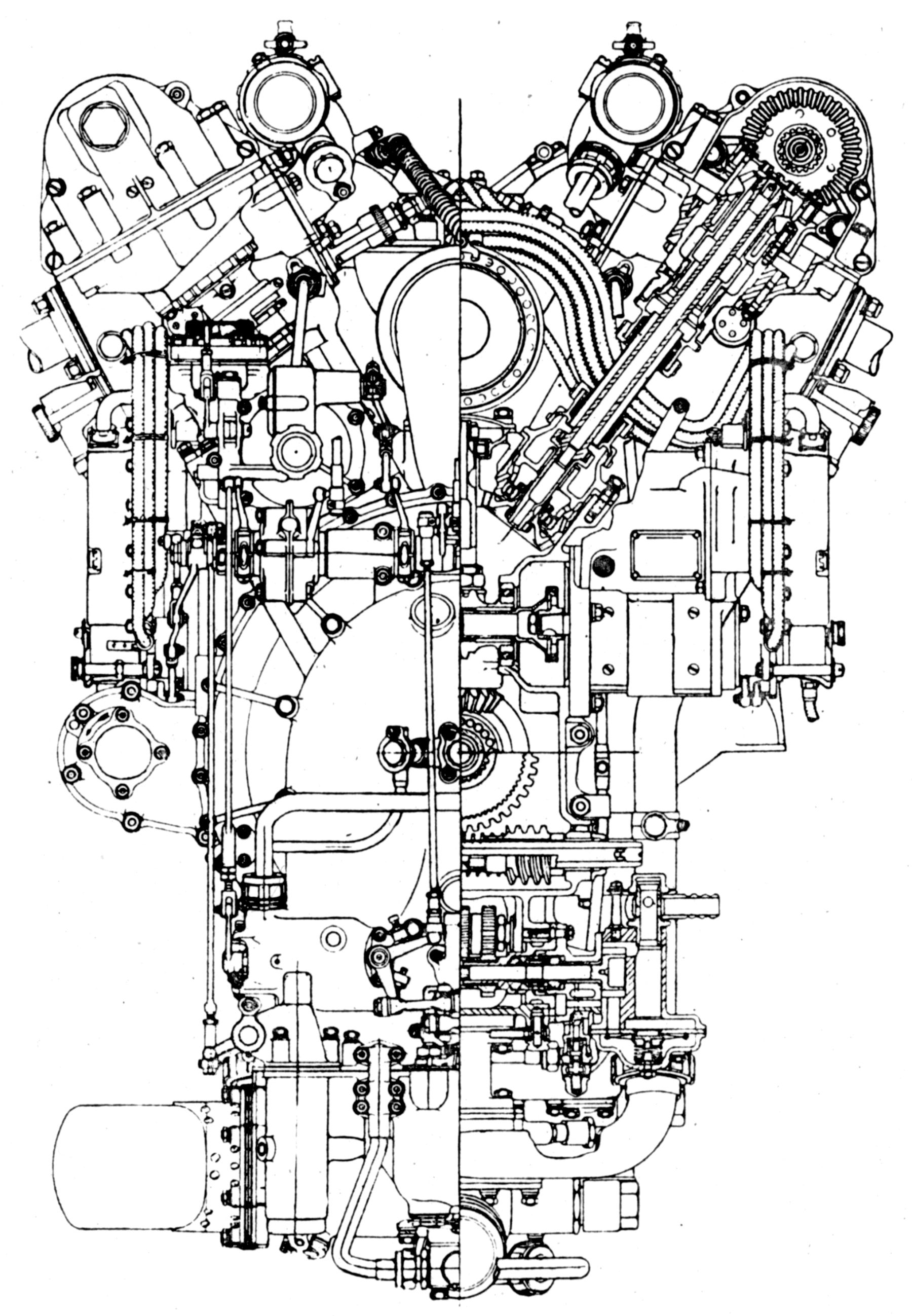
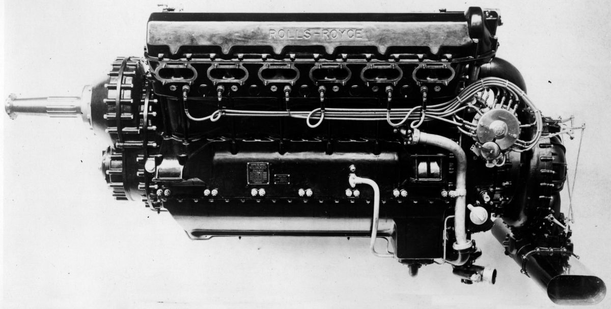
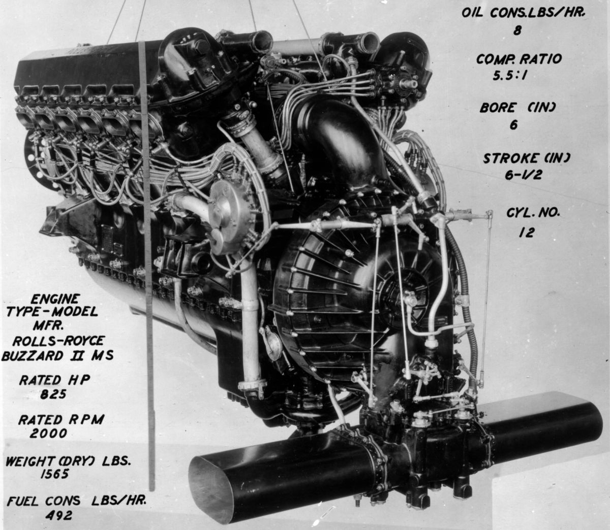
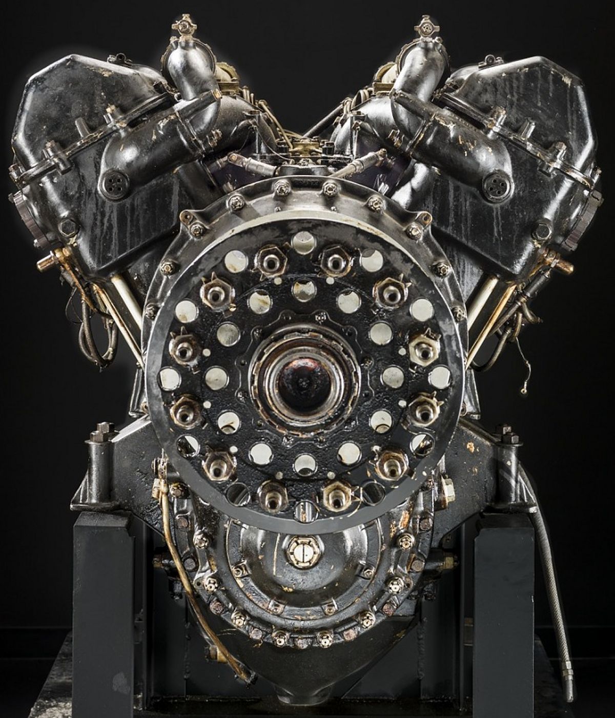
The Buzzard (H-type) series appeared with a 6.000" (152.4 mm) bore, 6.600" (167.64 mm) stroke and 2,239.33 (36.70 l) displacement. All produced 825 hp at 2,000 rpm unsupercharged. Medium superchargers ran at a 1:5.59 ratio while full superchargers ran at a 1:10.0 ratio. Buzzards were 75.7" (1,923 mm) long, 30.6" (775 mm) wide, 44.4" high (1,128 mm) high and weighed 1,540 lb (699 kg).
The Buzzard IMS (H.XIMS) (1927), with a 5.0:1 compression ratio and 1.5823:1 propeller reduction ratio, produced 955 hp at 2,300 rpm and 2,000 ft (610 m) with medium supercharging; 9 were built.
The Buzzard IIMS, (H.XIIMS) (1932-33), with a 5.3:1 compression ratio and 1.8083:1 propeller reduction ratio, produced 825 hp at 2,000 rpm and 2,000 ft (610 M) with medium supercharging and 955 hp at 2,300 rpm and 2,000 ft (610 m) with full supercharging; 69 were built.
The Buzzard IVMS, (H.XIVMS) (1931-33), with a 5.5:1 compression ratioand 2.0964:1 propeller reduction ratio produced 840 hp at 2,000 rpm and 2,000 ft (610 M) with medium supercharging and 937 hp at 2,300 rpm and 2,000 ft (610 m) with full supercharging; 22 were built.
Buzzard superchargers, timing gears and accessories were driven by a torsionally-flexible quill shaft geared to the crankshaft and the supercharger drive included a centrifugally-enhanced friction clutch, preventing gearing damage from sudden engine rpm changes. The mixture was drawn through a double-venturi Rolls-Royce carburetor incorporated in the supercharger housing. [A39, Wikipedia)
 |
 |
 |
 |
 |
 |
 |
| Buzzard II (NARA) | Buzzard XIV (Wikimedia) | |||||
The Rolls-Royce R (1929 – 1931) was developed from the Buzzard for the 1929 Schneider Trophy Race. Although the bore and stroke remained unchanged, there were numerous other improvements. It had become clear during the 1927 races that the racing Napier Lion could be developed no further. The Rolls-Royce R filled this void.
A.J. Rowledge, who had come to Rolls-Royce from Napier, did much of the R's design. The compression ratio was increased to 6.0:1. A new, larger double-sided supercharger running at 7.034 times crankshaft speed was designed, four duplex RR-Claudel-Hobson carburetors were fitted, each cylinder had two additional saddle hold-down studs, the cylinder banks were redesigned and cast from HR-50 aluminum alloy to improve valve cooling, and the valve covers were angled as a drag-reduction measure. The fork-and-blade connecting rods were strengthened, and a 5:3 propeller reduction ratio was introduced. The resulting engine produced 1,900 hp at 3,000 rpm and 13.5 psi boost continuously for one hour when running a special fuel mix of Rumanian gasoline, benzol (benzene and toluene) and tetraethyl lead. A Supermarine S.6 designed by R.J. Mitchell and flown by Richard Waghorn won the 1929 contest at 328.63 mph.
The British government decided not to enter the 1931 contest, where a win would allow Great Britain to permanently claim the trophy. Lady Lucy Houston donated £100,000 to help finance the campaign. The connecting rods were changed from fork-and-blade to articulated, the crankshaft was redesigned, sodium-cooled exhaust valves were introduced, the supercharger gear ratio was changed to 1:7.47, and an exotic fuel mixture consisting of gasoline, methanol, benzol, acetone and tetraethyl lead was used. With a sprint rating of 2,783 hp at 3,400 rpm and 17.5 psi boost, the revised R engine was fitted into Mitchell's Supermarine S.6B and on 13 Sep won the 1931 Schneider Trophy Race at 340.08 mph. On 29 Sep 1931 the same airplane/engine combination set a world seaplane record at 407.5 mph. The R was 100" (2,540 mm) long, 32" (814 mm) wide and 42" (1,067 mm) high. A total of 20 R engines were built. [A39, Wikipedia]
 |
 |
 |
 |
 |
 |
| (Wikimedia) | (Wikimedia) | (Wikimedia) | |||
Rolls-Royce continued developing piston aircraft engines into the 1950s; these engines are well documented elsewhere.
References
Angle, Glenn D, ed. Aerosphere 1939 (New York, New York: Aircraft Publications, 1940).
Anble, Glenn D, ed. Airplane Engine Encyclopedia (Dayton, Ohio: Otterbein Press, 1921).
Wiki = Wikipedia.
Source Abbreviations: A39 = Aerosphere 1939; AEE = Airplane Engine Encyclopedia; Flt = Flight Magazine; NARA = U.S. National Archives and Records Administration; UKNA = United Kingdom National Archives; Wikimedia = Wikimedia Commons.
Send mail to
![]() with questions or comments about this web site.
with questions or comments about this web site.
![]()