Selected Early Engines
R.A.F., Rapp, Rausenberger, Renard, Renault, R.E.P., Rheinische, Roberts, Rolls-Royce
Compiled by Kimble D. McCutcheon
Published 20 Feb 2023; Revised 13 Apr 2023
R.A.F.
The Royal Aircraft Factory (RAF), a government experimental facility located at Farnboro, England, designed and developed several aircraft and aircraft engines.
The RAF 1, designed in 1913, was an air-cooled 90° V-8 rated at 90 hp. With a 100 mm (3.937") bore and 140 mm (5.512") stroke it displaced 8.796 l (536.79 in³).
|
|
|
| RAF-1B (NARA) | RAF-1A (NASM) | RAF-1A (AEE) |
The improved 1914 RAF 1A, with its 4.2:1 compression ratio, developed 105 hp at 1,800 rpm and weighed 199.6 kg (440 lb). Because of the cooling arrangement, these engines were only used only as tractors. The propeller speed was reduced by plain spur reduction gears that, together with the air scoop, resembled a Renault design, from which the RAF-1A was probably copied. The cast-iron cylinders had integral horizontal cooling fins around the barrel, and longitudinal fins across the head. The F-head cylinders had the exhaust valve directly above the inlet. The camshaft in the Vee operated the inlet valves directly through tappets and the exhaust valves via push rods and rocker arms. The exhaust valves seated directly in the cylinder head, and the inlet valves seated in detachable cages that facilitated exhaust valve removal. The inlet valve diameter was 45 mm (1.772") and its lift was 9 mm (0.354"). Exhaust valve diameter was 40 mm. (1.575") and its lift 7.5 mm (0.295"). The inlets opened 10° late and closed 40° late; the exhausts opened 52° early and closed 8° late. H-section connecting rods with plain bearings and two-bolt caps were placed side by side on the crankpins, resulting in staggered cylinder banks. The pistons were originally made from cast iron and later from aluminum alloy. The crankshaft was carried upon four roller bearings and one ball bearing, while the propeller shaft was supported by two ball bearings. A light steel flywheel also served as an oil circulating pump; the lubrication system was gravity and splash. The fuel and oil consumptions were 0.63 and 0.071 lb/hp/hr. A Claudel-Hobson carburetor with a single float and two venturis was mounted below at the engine aft end. Two magnetos supplied ignition.
The RAF-1B appeared in 1915 with a cylinder bore increase to 105 mm (4.134") and corresponding displacement increase to 93698 l (591.81 in³). Stroke and compression ratio remained the same as the RAF 1A. It developed 115 hp at 1,800 rpm.
The 1915 RAF-1C had aluminum cylinders with shrunk-in liners and side valves. Both 100 mm (3.937") and 105 mm (4.134") bores were tried with the 140 mm (5.512") stroke and 4.5:1 compression ratio.
The RAF-1D, an RAF-1A with overhead valve aluminum cylinders similar to those used on the RAF-4D design and 4.7:1 compression ratio, developed 150 hp at 2,000 rpm and weighed 189.61 kg (418 lb).
The RAF-1E was an RAF-1D using RAF-4E cylinders.
 |
 |
 |
| RAF-3A (NARA) | ||
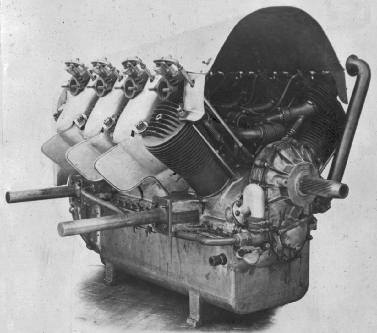
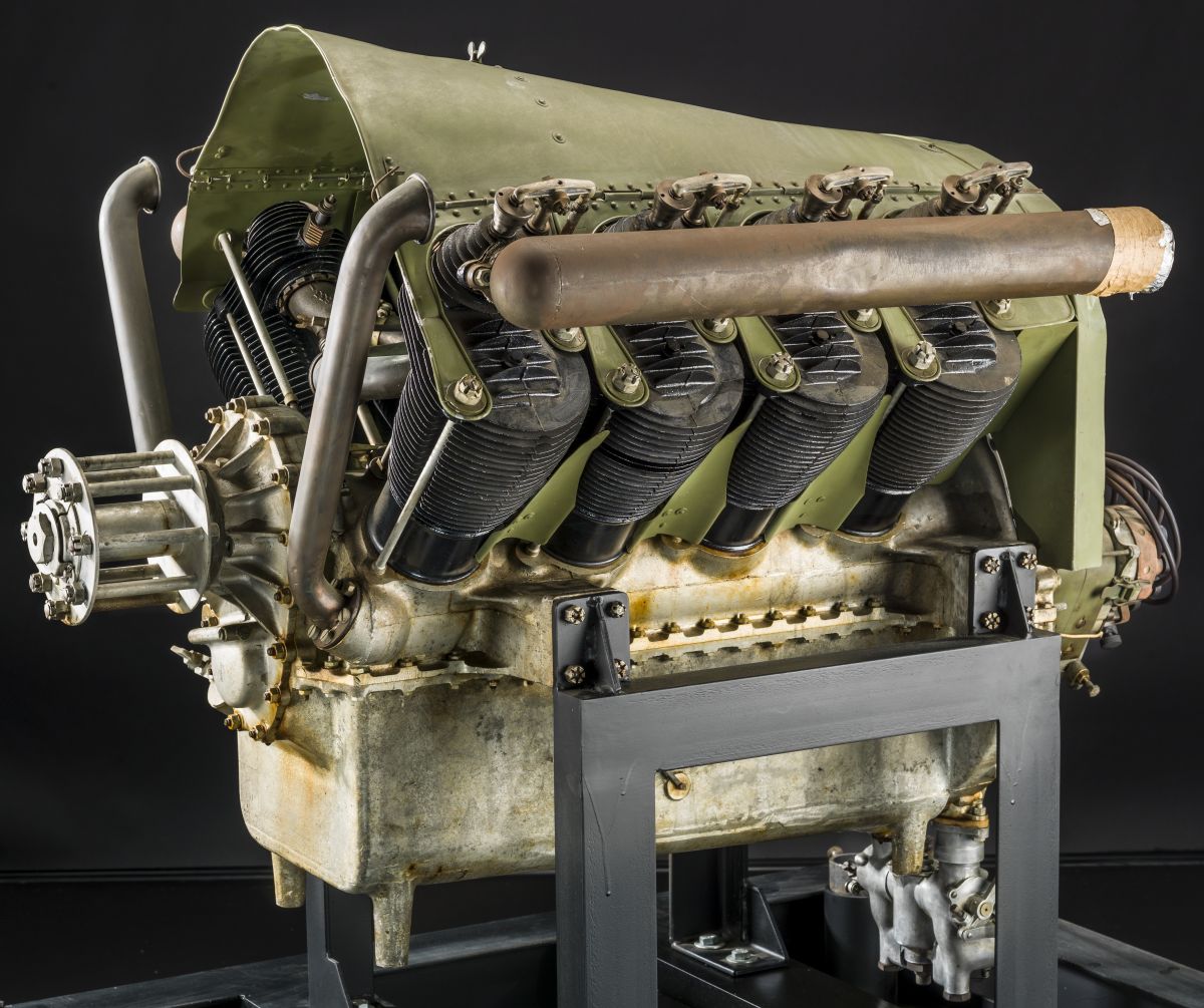
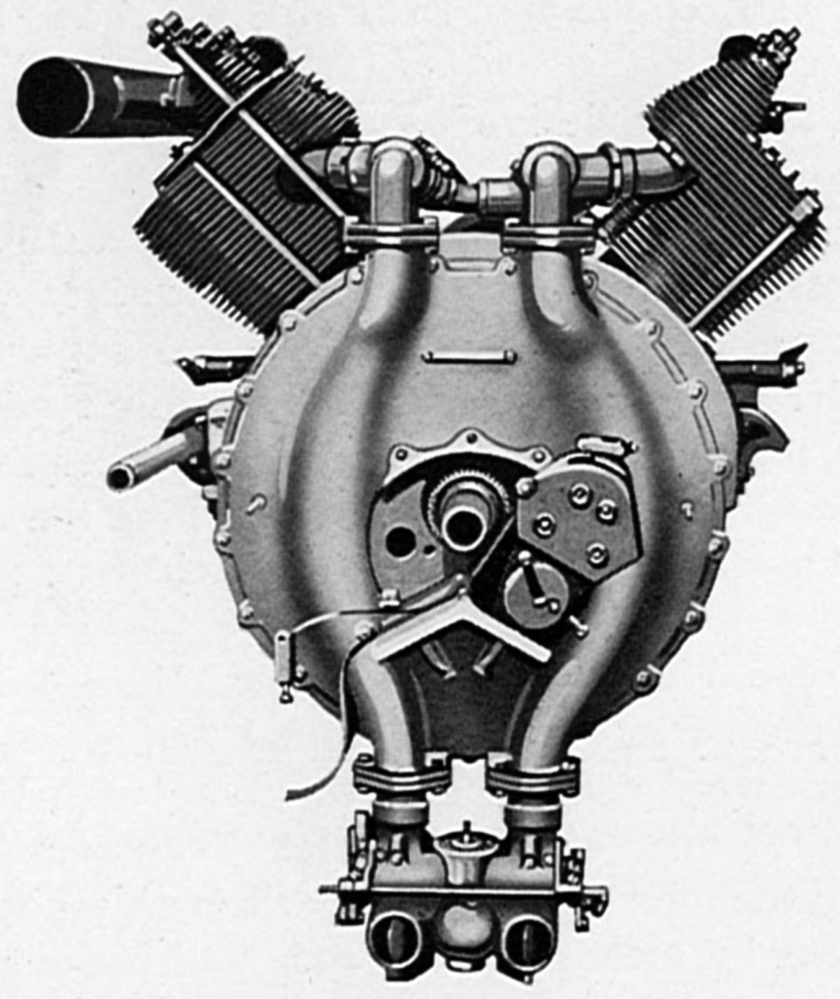
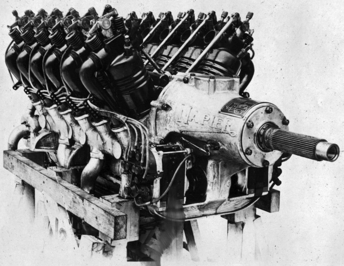
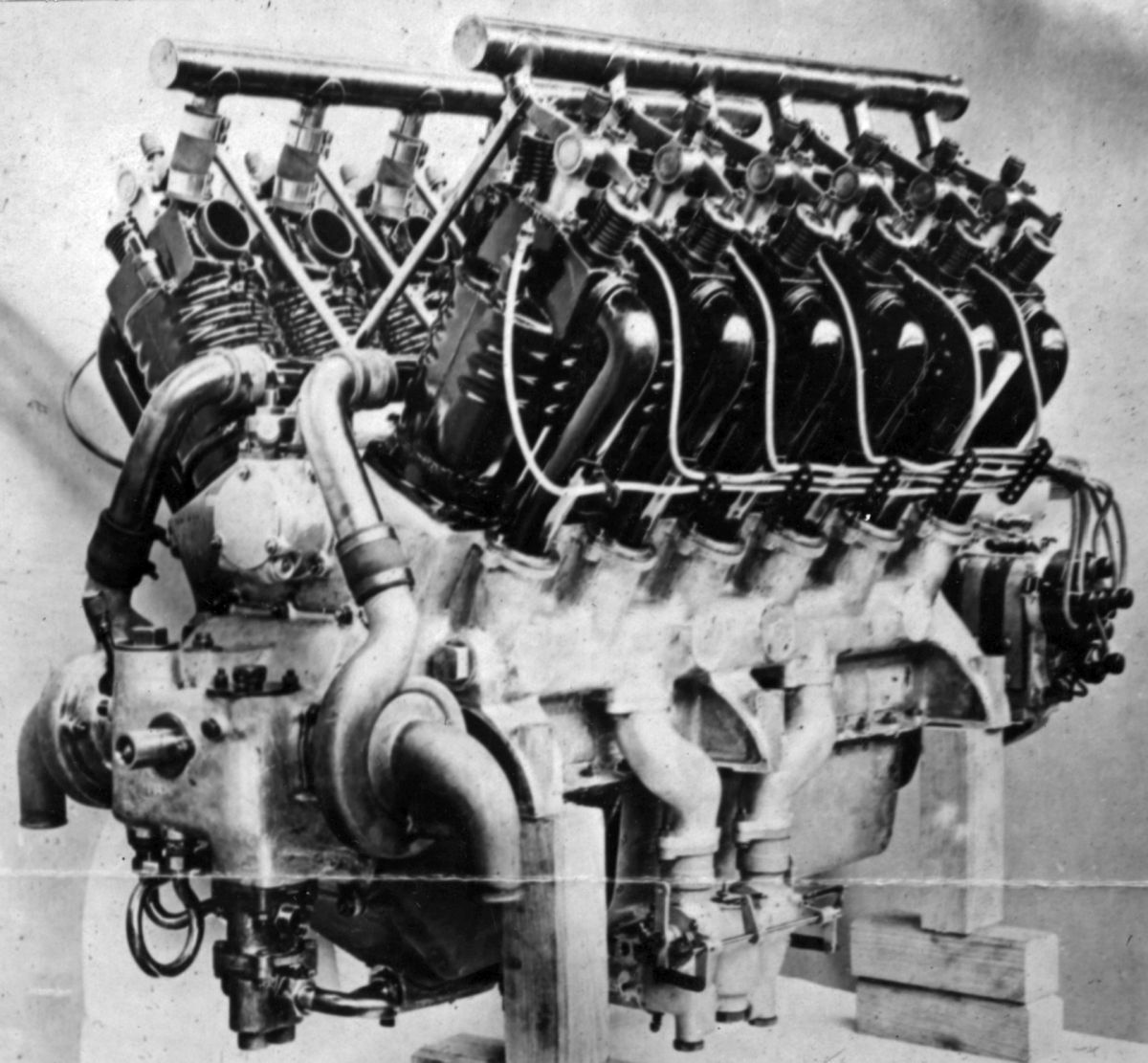
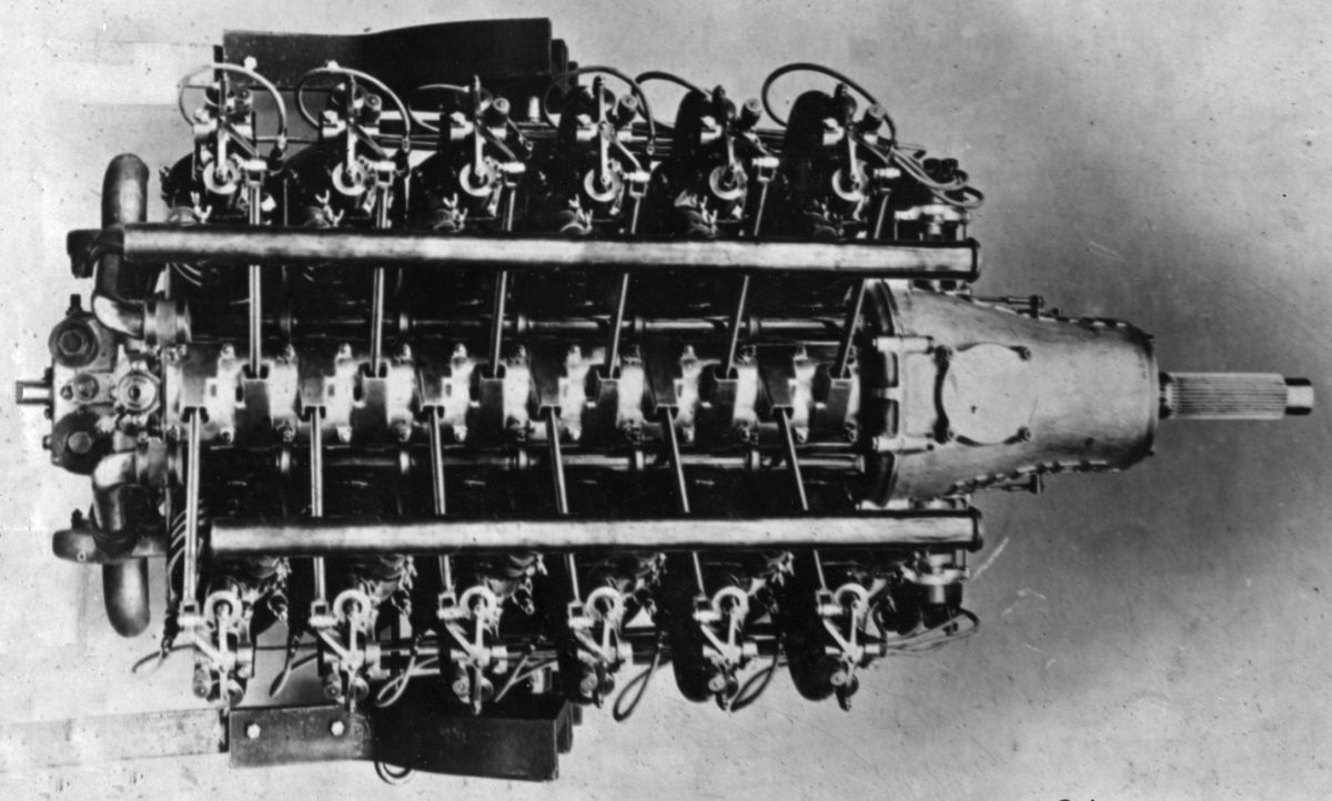
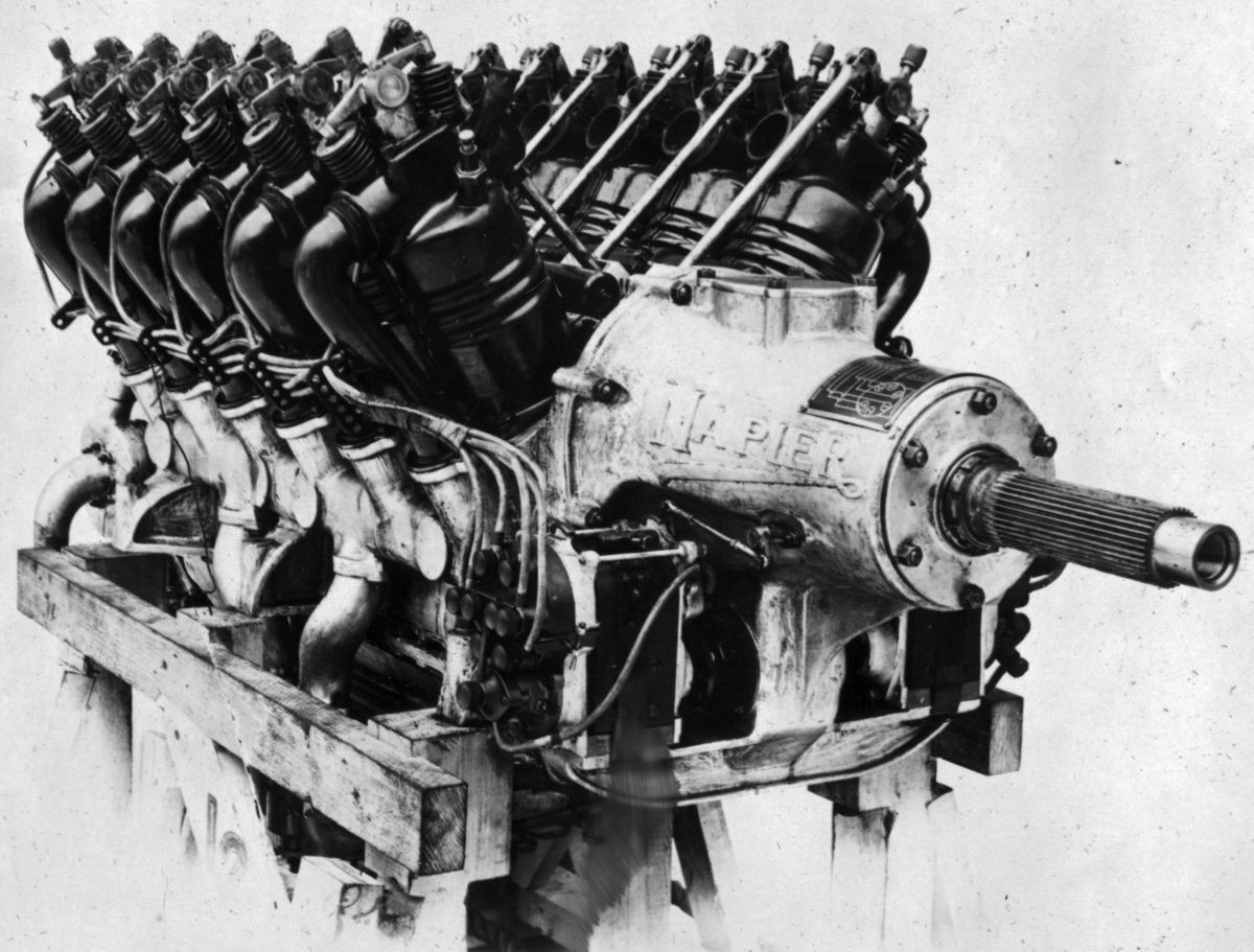
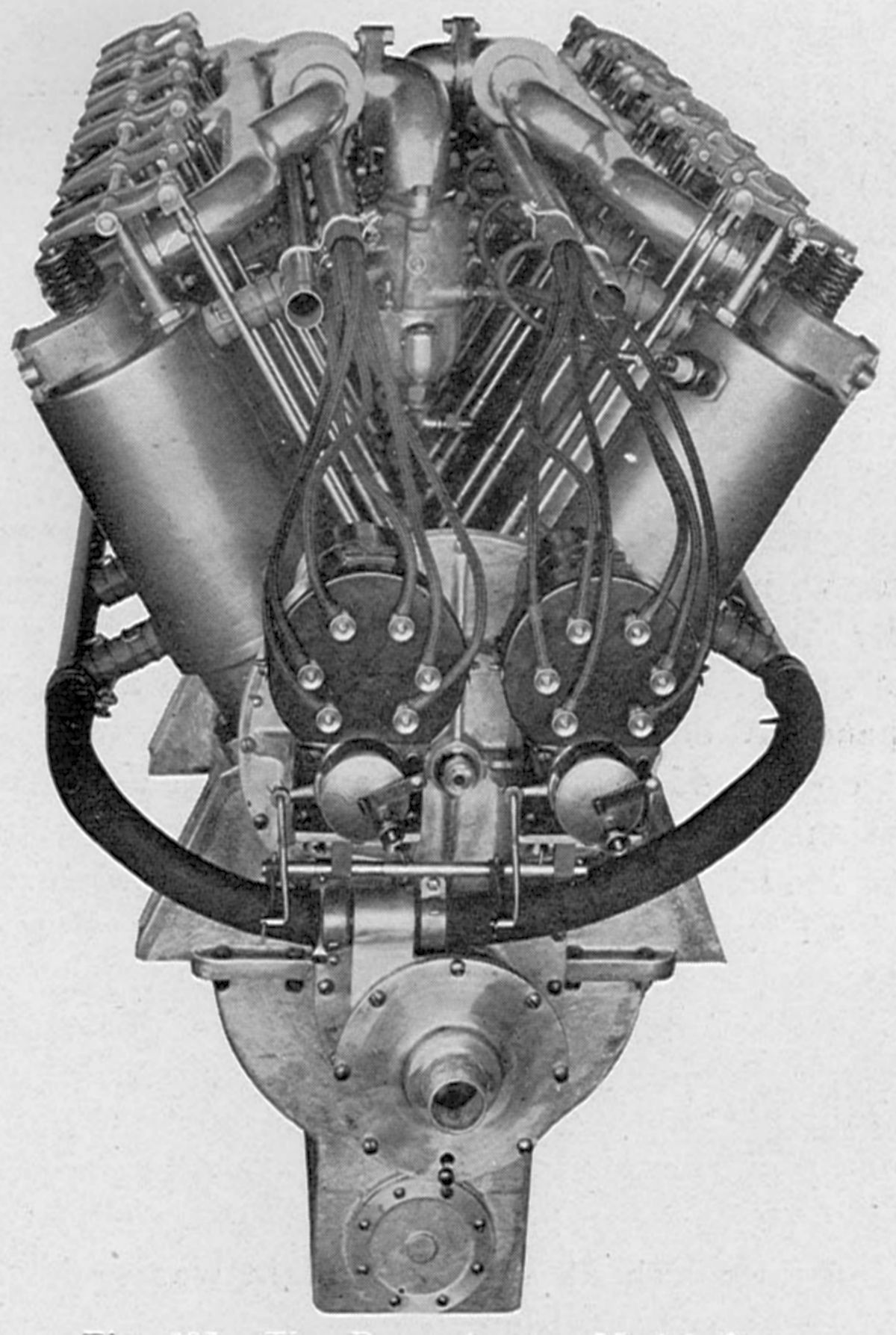
The 1914 water-cooled RAF-3A was a 60° V-12 developed from the 1914 200 hp prototype RAF-3 of similar construction, bore and stroke, but run very little. The RAF-3A, with its 114.4 mm (4.500") bore, 139.7 mm (5.500") stroke, 17.20 l (1,046.68 in³) displacement and 4.75:1 compression ratio, developed 242 hp at 1,800 rpm. With a 5.5:1 compression ratio it delivered 266 hp. The individual cylinders were machined from steel drop forgings with integral valve ports. Corrugated sheet-steel water jackets were welded in place. The tulip-shaped valves were inclined in the head and operated by a rocker arm and single push/pull rod from a camshaft mounted on roller bearings in the Vee. The inlet valves opened 24° late and closed 50° late; the exhaust valves opened 57° early and closed 2° late. The six-throw crankshaft was supported on eight roller hearings held by individual steel-reinforced aluminum caps with . The crankshaft drove the propeller shaft at half speed through plain spur reduction gears. The propeller shaft was carried upon two roller bearings, and was joined by splines to the camshaft. The articulated connecting rods had H-section shanks. The ribbed aluminum pistons featured cast-in steel piston pin bushings. Three compression rings were fitted above the piston-pin; an oil-scraper ring was below. The inlet manifolds were cast integral with the upper crankcase half, and each was served by a duplex Claudel carburetor. The mixture was fed to the cylinders on the outside through individual steel pipes. Pressure and splash lubrication was used. One gear set comprised a pressure pump for the bearings; two sets were used for scavenging the sump. Fuel and oil consumptions were 0.54 and 0.023 lb/hphr. Cooling water was circulated by two centrifugal pumps, one for each cylinder bank. Two six-cylinder magnetos mounted crosswise at the propeller end furnished ignition. Armstrong Whitworth built 29 RAF-3As, Napier & Son 260.
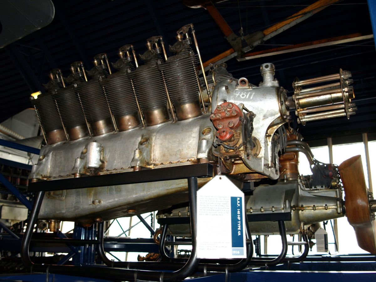
The RAF-4, an air-cooled 60° V-12 with RAF-1A 100 mm (3.937") bore by 140 mm (5.512") stroke cylinders, displaced 13.195 l (805.19 in³), produced 140 hp at 1,800 rpm and weighed 289 kg (637 lb) lb. The flywheel oil pump, along with many other important RAF-1A features were retained. Its inlet valves opened 12.5° late and closed 43.5° late; exhaust valves opened 61° early and closed 17° late.
The RAF-4A, produced in 1915, eliminated the flywheel and substituted two gear-type oil pumps. An experimental version was also constructed using Berriman-Daimler designed cylinders with aluminum heads, steel liners, and copper cooling fins. It developed 170 hp at 1,800 rpm.
 |
 |
| RAF-4A (Wiki) | RAF-4D (NARA) |
The RAF-4D, produced in 1916, had aluminum cylinders with shrunk-in steel liners that were secured with two studs each. Overhead tulip-type valves, the inlet having a 43 mm (1.692") and the exhaust 40 mm (1.575") clear diameter. Aluminum pistons were fitted with two rings. With its 4.7:1 compression ratio, the RAF-4D produced 220 hp at 2,000 rpm and weighed 315.3 kg (695 lb).
The later RAF-4E had improved four-stud cylinders with larger valves and was rated 210 hp at 2,000 rpm.
The RAF-5 was a RAF-4A arranged as a pusher. Its power output was reduced by about 10 hp due to an added cooling fan. This arrangement was similar to the air-cooled eight and twelve-cylinder Renault designs.
The RAF-7 was a high-compression RAF-3A fitted with high-lift cams and outside exhaust. It produced over 300 hp.
The RAF-21 was an improved ABC Dragonfly fitted with new cylinders designed by the Royal Aircraft Establishment. It developed about 350 hp.
The RAF-22 was an ABC Wasp with redesigned cylinders developed 180 – 190 hp.
Rapp
If at first you don't succeed, fail, fail again – Karl Rapp's little engines that couldn't.
Karl Friedrich Rapp (24 Sep 1882 ‑ 26 May 1962) was a German mechanical engineer who worked at the Züp automotive concern (1908 – 1911) and at Daimler-Motoren-Gesellschaft (1911 ‑1912) before becoming an engineer and operations manager at a Flugwerk Deutschland GmbH Munich division dedicated to aircraft engine manufacturing (20 May 1912).
 |
 |
| FD 1416 (WC) | FD 1416 (WC) |
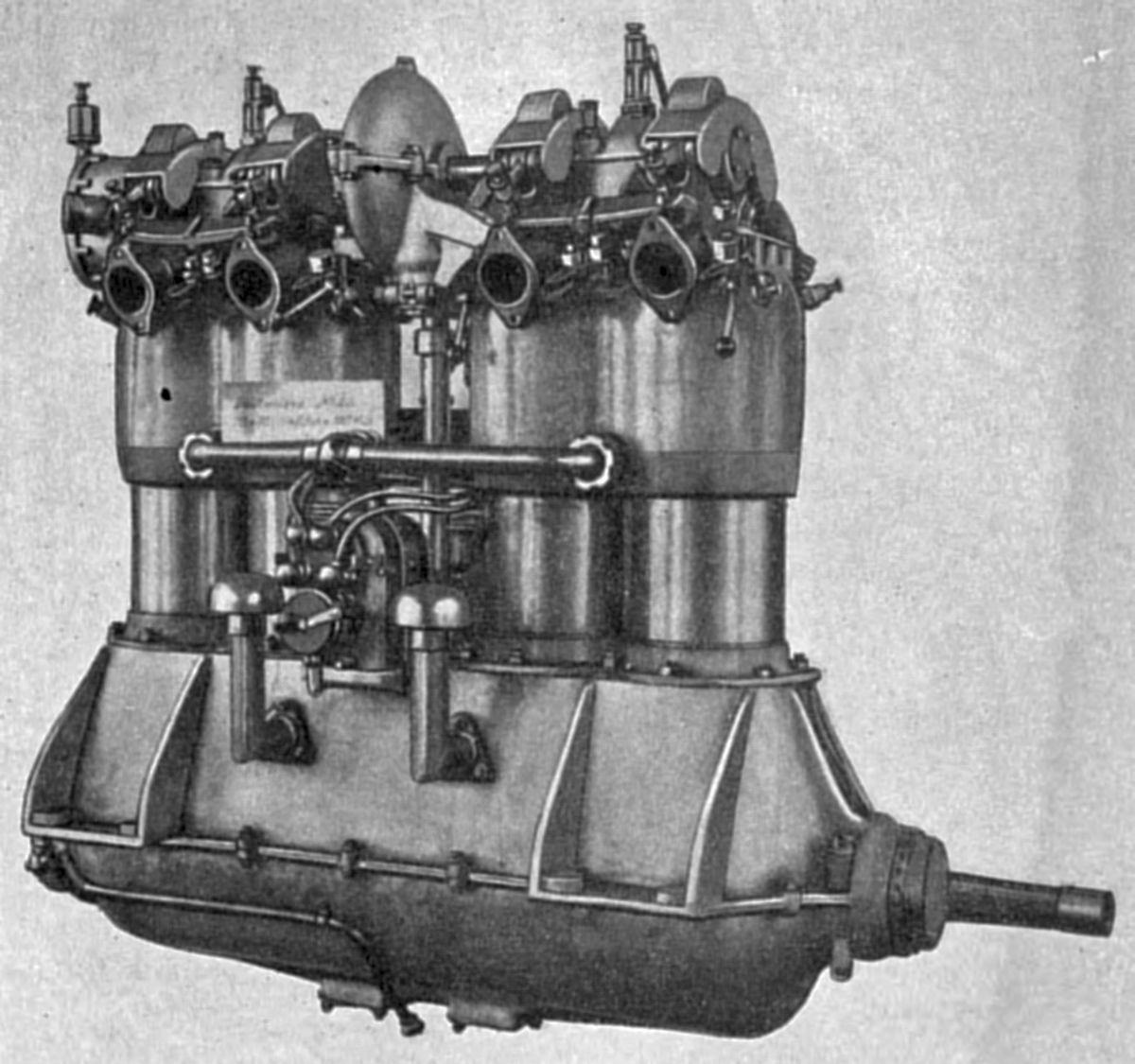
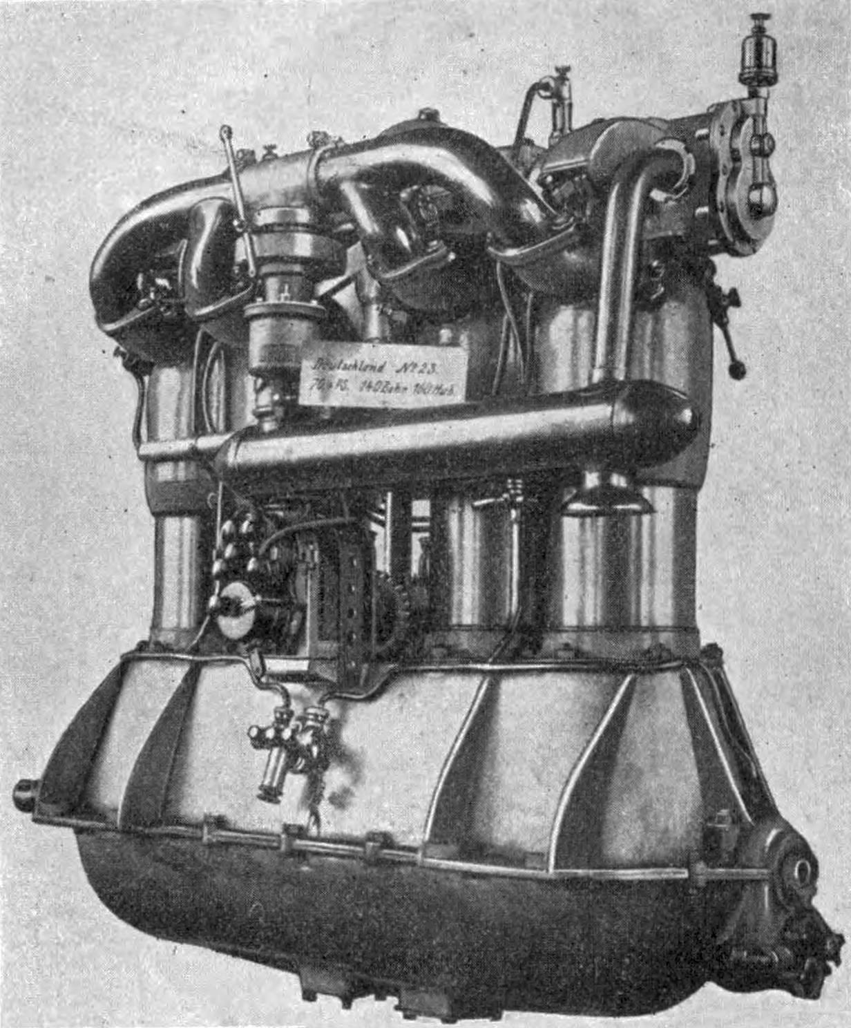
It was there he designed the FD 1416, a water-cooled single-overhead-cam vertical four for the 1912/13 Kaiserpreis (Kaiser's Trophy) aircraft engine contest. With a 140 mm (5.512") bore and 160 mm (6.299") stroke, it displaced 9.852 l (601.21 in³) and produced 90 hp at 1,100 rpm. It failed to perform well, was considered too heavy and had a high specific fuel consumption. Flugwerk Deutschland GmbH was dissolved on 16 Apr 1913.
Karl Rapp tried and failed to establish a new aircraft/engine concern at the Flugwerk Deutschland GmbH site. He then teamed with Julius Auspitzer to found Karl Rapp Motorenwerke GmbH, where he managed operations; Auspitzer provided the capital. Rapp attempted to build a water-cooled 125-hp in-line six displacing 14.778 l (901.81 in³) weighing 215 kg (474 lb) for the 2nd Kaiserpreis, but it was not completed in time.
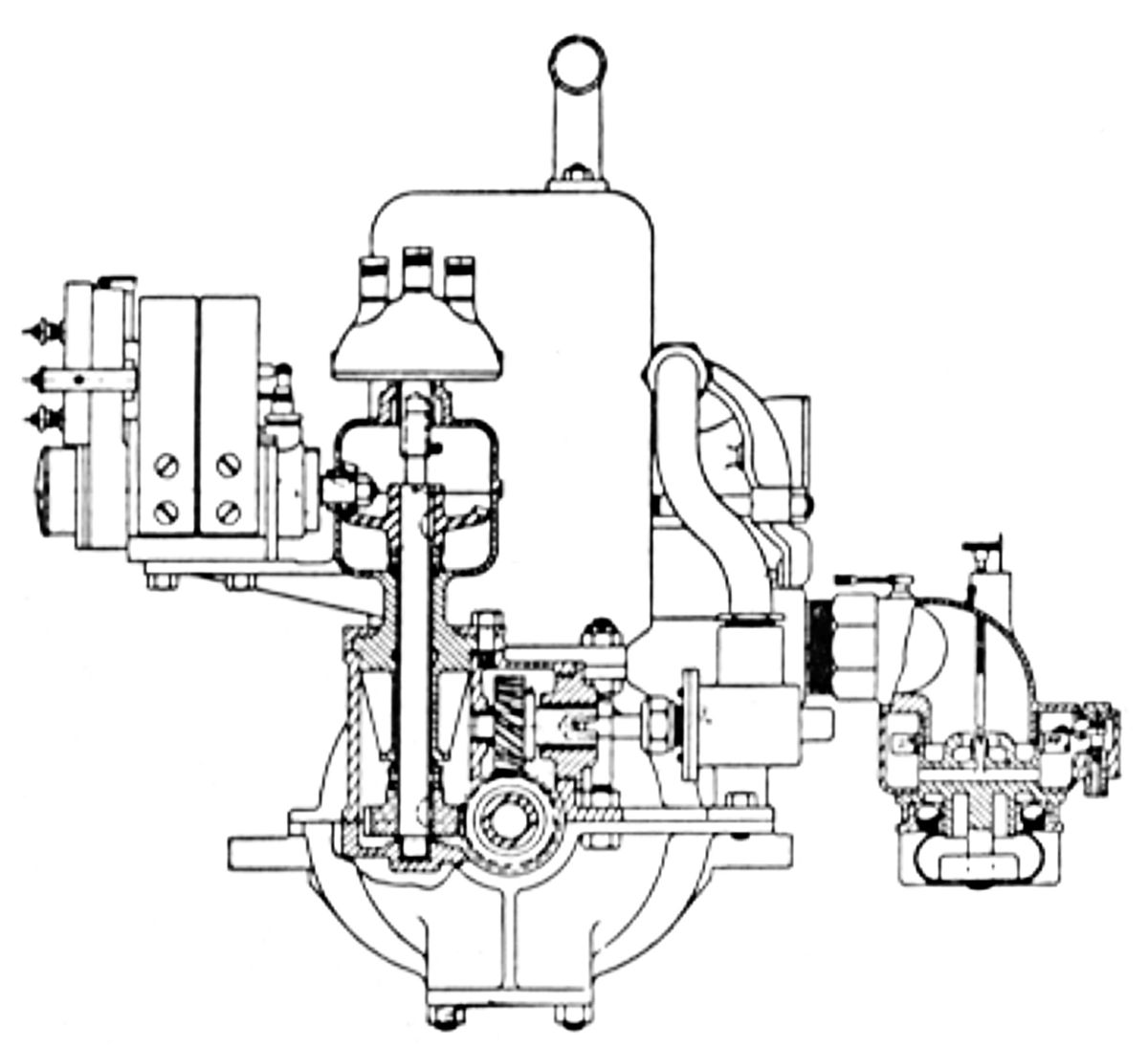
Meanwhile, Karl Rapp offered the Rapp 100 hp engine to the Prussian Army Administration on 1 Nov 1913. Some improvements had been made since the 1912 Kaiserpreis contest, but the basic design remained essentially unchanged. The cylinder assemblies consisted of two separate forged steel cylinder liners that were screwed into paired cast steel cylinder heads with integral cooling jackets. The valve seats were separate parts screwed into the cylinder heads that could be easily removed for maintenance; the exhaust seats were water-cooled. The two inlet valves were held in their seats by a single pivoting leaf spring. The exhaust valves were similarly retained. Each cylinder's valves were actuated by an overhead camshaft, roller tappets and rocker arms. The camshaft was driven by a vertical timing shaft and bevel gears between the two cylinder assemblies. Two magnetos, also driven by the timing shaft, fired two spark plugs per cylinder. The cast aluminum crankcase parted at the crankshaft centerline and supported the three crankshaft main bearing journals. A gear pump at the engine rear and driven by the crankshaft supplied pressure lubrication to the crankshaft journal bearings. The original center-mounted Cudell-G.A. carburetor on the intake side was replaced by a Zenith carburetor mounted at the engine rear, which fed the cylinders via a single pipe. The carburetor received preheated air via intake air pipes routed through the exhaust. A geared water pump was relocated from the camshaft aft end to the crankshaft aft end.
Observation: While the paired-cylinder assembly construction was not unusual for engines of this era, driving the camshaft and magnetos from the engine center was novel. This approach lent itself to many configurations with a minimal parts count. However, this scheme also caused the crankshaft to be lengthened at the very place it needed to be short, which introduced unpredictable torsional behavior and bearing loads. The author opines that this novel construction was the root cause of Rapp's engine troubles.
While the 100 hp four-cylinder engine was installed in some contemporary aircraft, it apparently did not find much success with the German military authorities, which by this time were demanding smoother, more powerful six-cylinder engines. [Wiki: Rapp 100 hp]
 |
 |
 |
| Rp II (WC, AEE) | Rapp 200 hp (AEE) | |
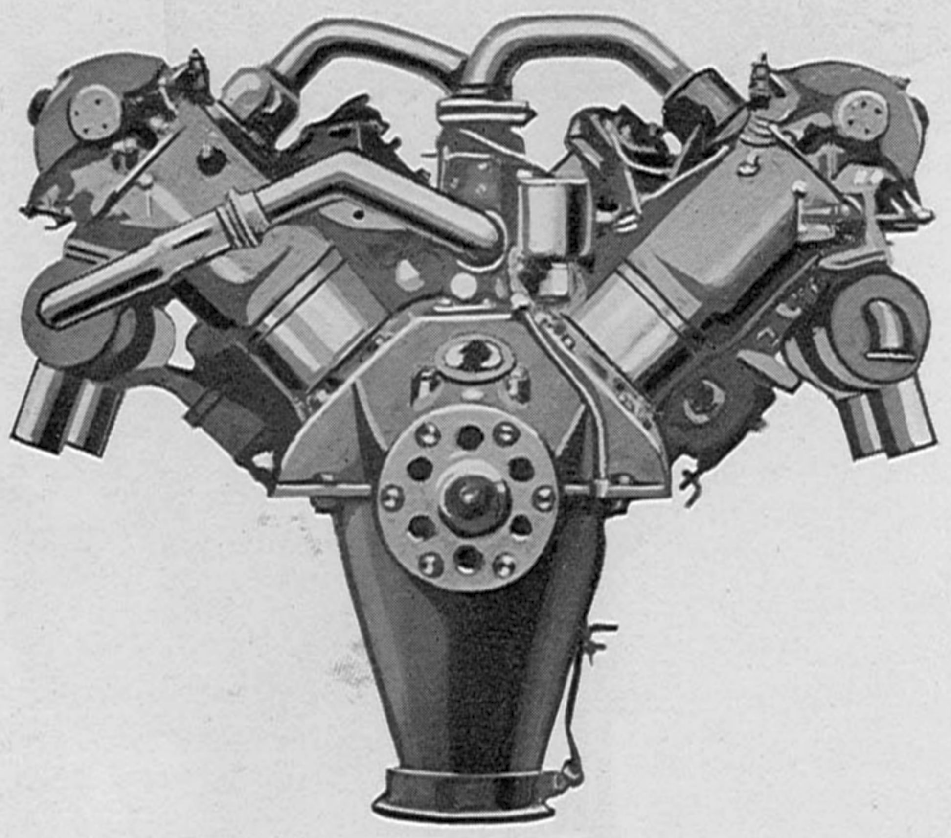
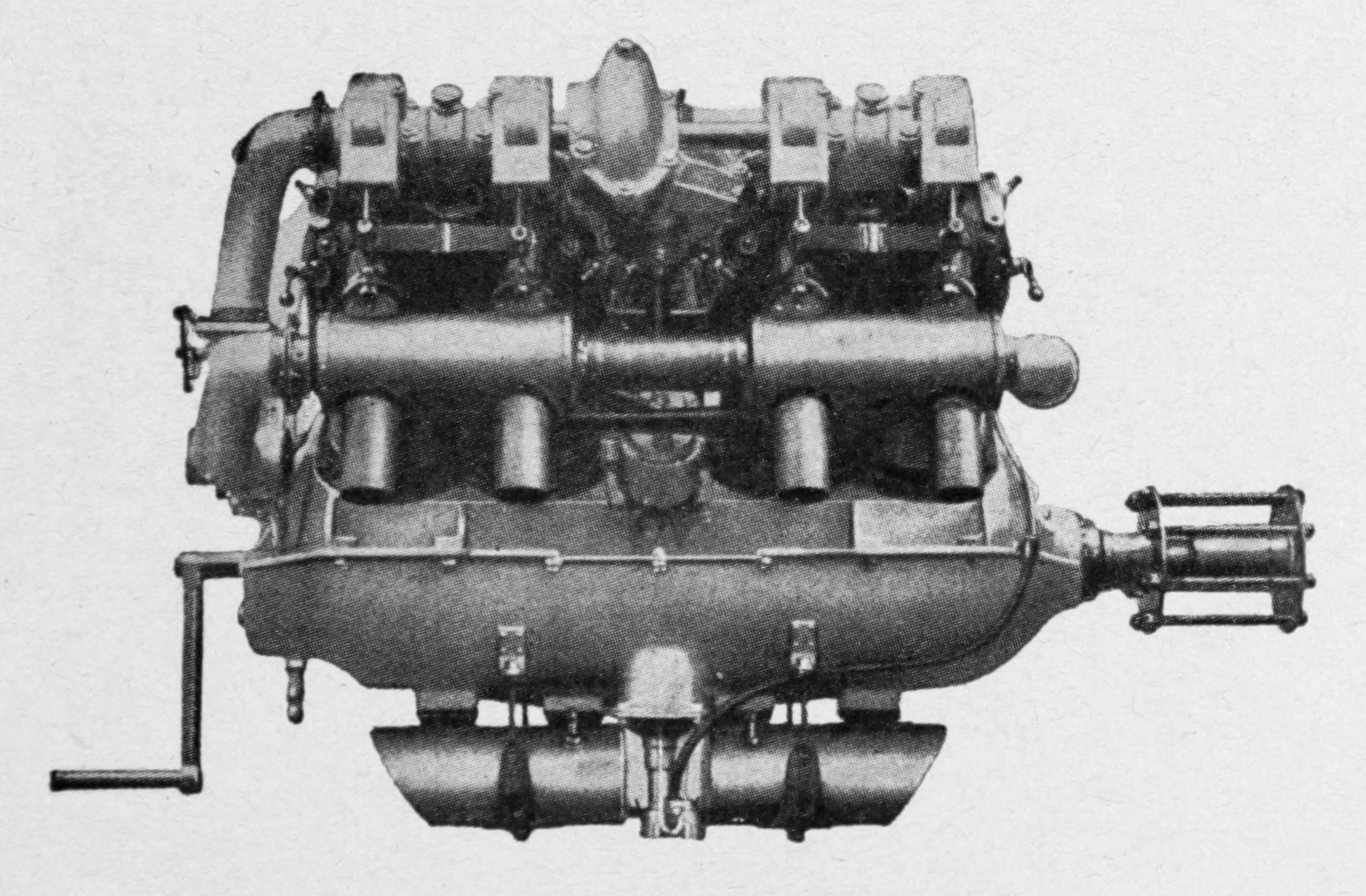
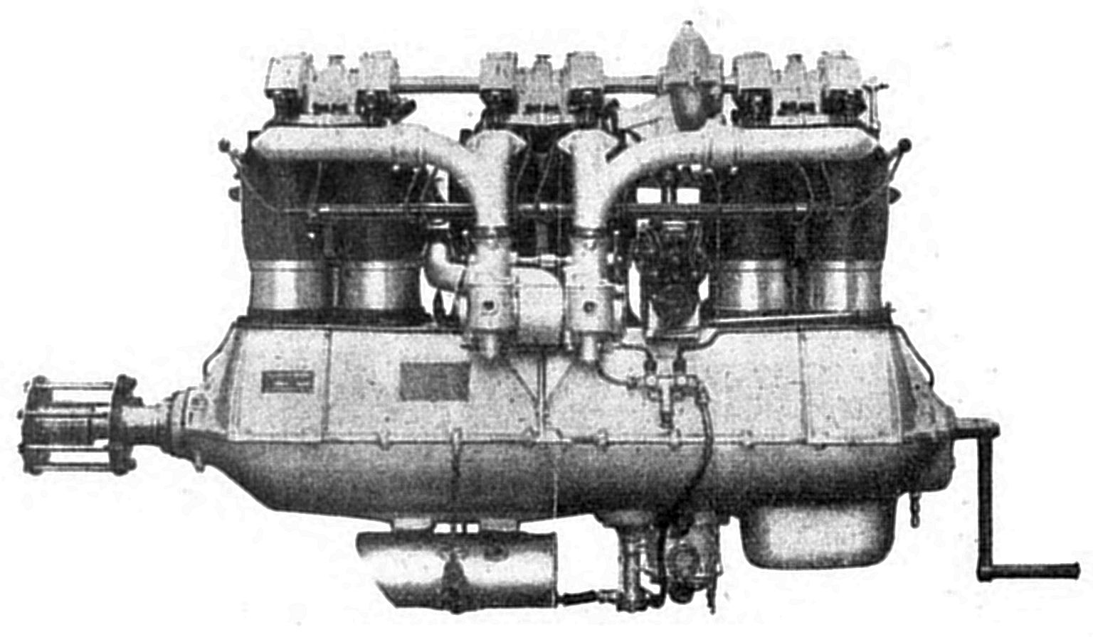
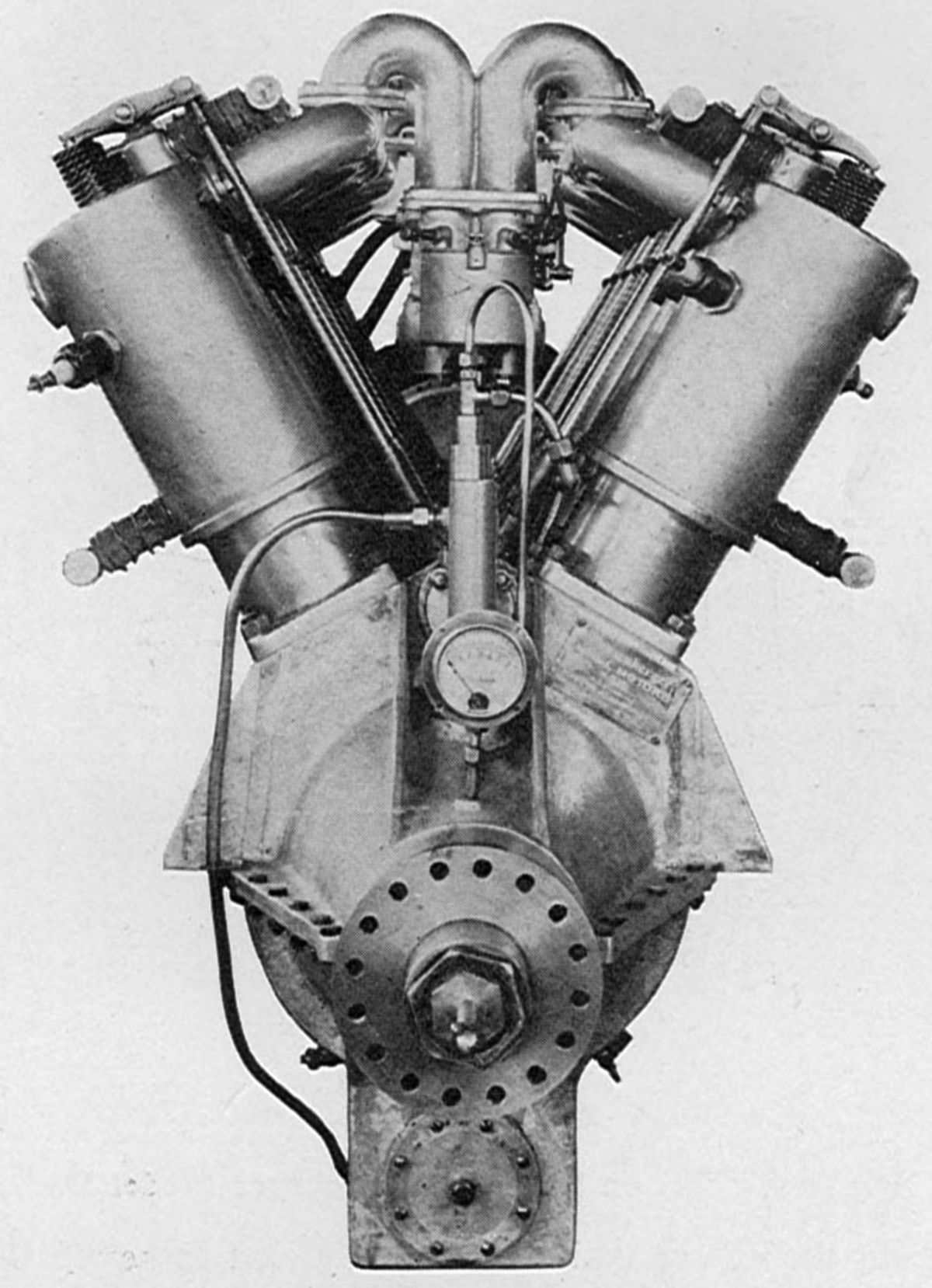
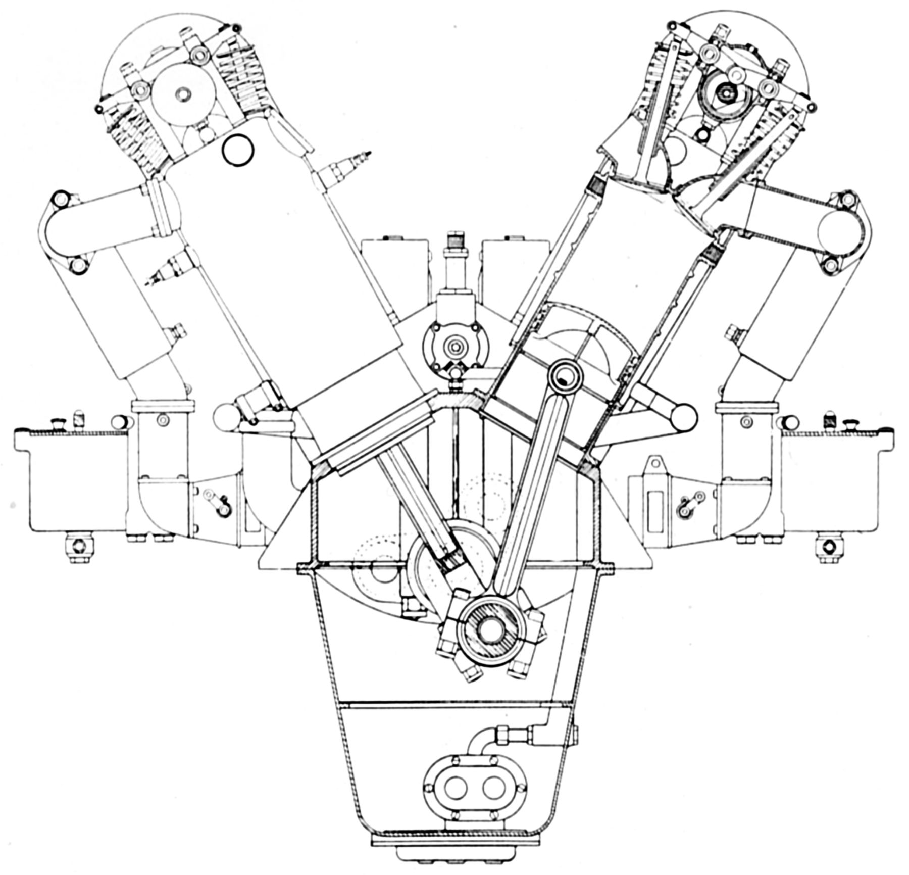
The Rp II, a 1915 water-cooled 90° V-8 with a 115 mm (4.528") bore and 140 mm (5.512") stroke that displaced 11.633 l (709.91 in³), was rated 125 ‑ 145 hp at 1,400 rpm and weighed 220 kg (485 lb). It retained the paired-cylinder construction previously used on Rapp 100 hp cylinder banks.
As 1915 ended, the Austro-Hungarian Armed Forces ordered 40 Rp II engines destined for Lohner B.V and B.VI training aircraft, but they suffered recurrent carburetor fires and were soon removed from service. The intake manifold was inside the Vee and the exhausts outside. As with the Rapp 100 hp, the camshafts were driven by a timing shaft and bevel gears between the two cylinder assemblies. Two magnetos, one at each cylinder bank center, were also driven from the timing shafts. The crankcase was cast from aluminum in two pieces and parted at the crankshaft horizontal plane. The lower featured a tapered sump with an oil pressure pump at its lowest point. Oil was routed via an external line to the upper crankcase and distributed to the main crankshaft journals. A gear-type water pump installed in each cylinder bank circulated the cooling water. Two Zenith carburetors were both located between the cylinder banks. Each carburettor fed one four-cylinder bank. Preheated air could be directed to the carburetors via intake air pipes routed through the exhausts.
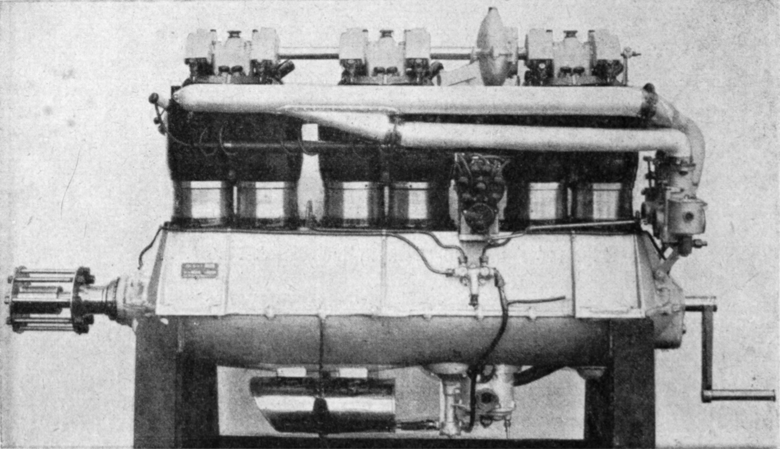
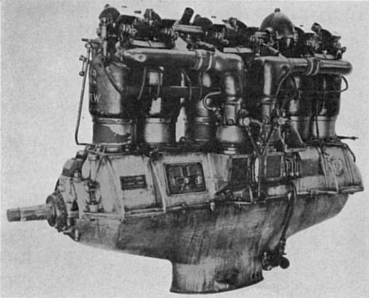
A 200 hp V-8 derived from the Rapp 100 hp design also appeared around 1915. It reverted to the same 140 mm (5.512") bore and 160 mm (6.299") stroke, but displaced 19.704 l (1,202.42 in³), produced 200 hp at 1,350 rpm and weighed 300 kg (661 lb). A gear pump mounted at the engine low point fed the oil from two cylindrical oil sumps, mounted fore and aft below the engine crankcase, to the main crankshaft journals. A separate gear-type water pump on either crankcase side circulated cooling water through each cylinder row. Two Zenith carburetors each fed a four-cylinder row. Different arrangements for the two carburettors were tried; some engines had the carburetors located at the engine rear while others had them located in the Vee. Air preheated via pipes routed through the exhaust could feed the carburetors. [Wiki: Rapp 125/145 hp, Rapp 200 hp]
 |
 |
 |
 |
| Rp III (WC) | Rp IIIa (AEE) | ||
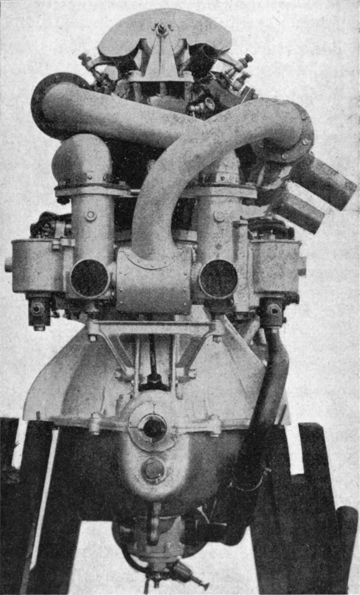
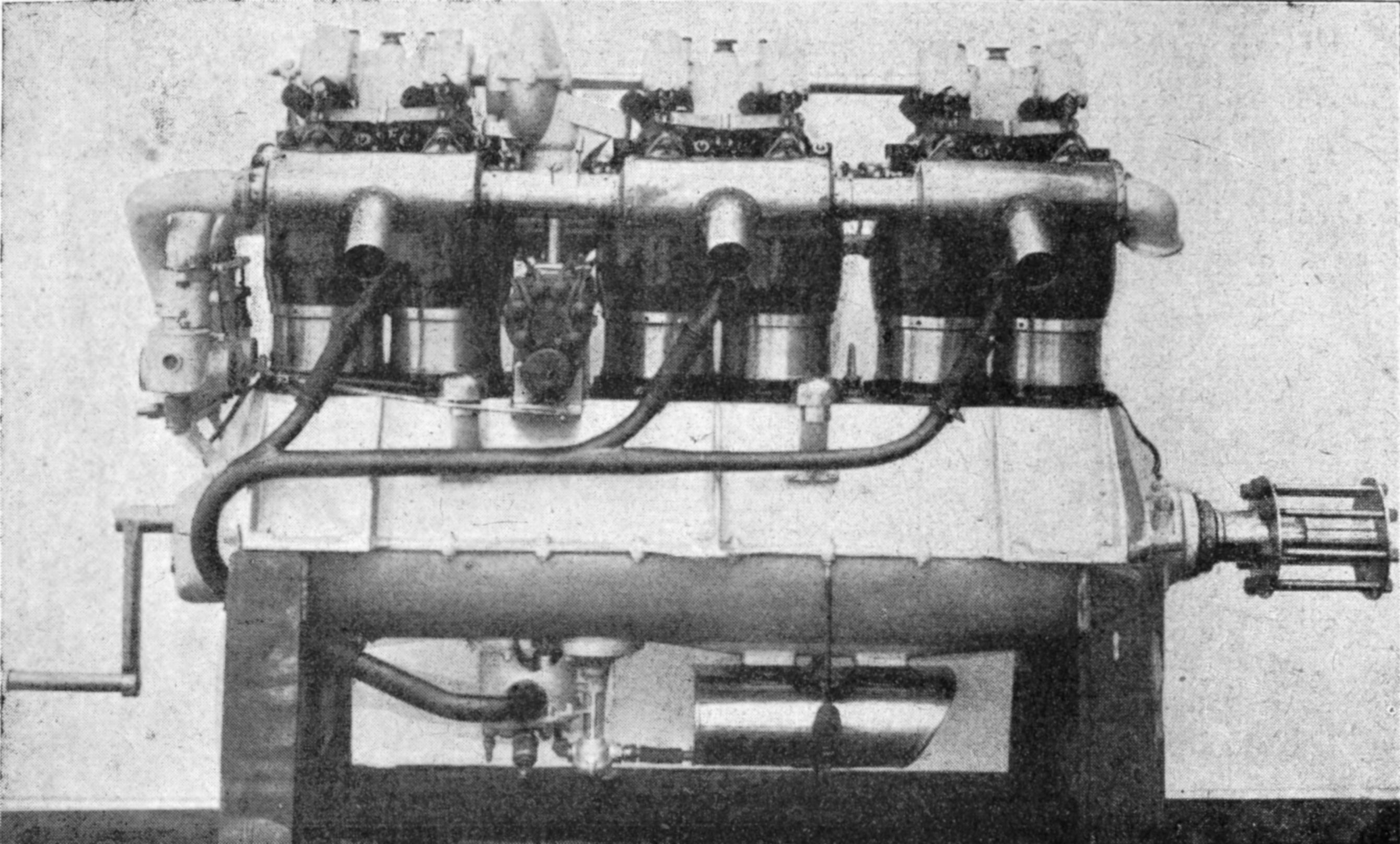
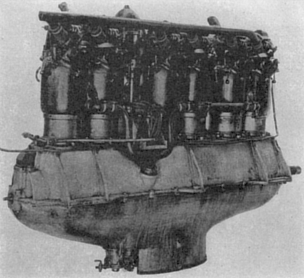
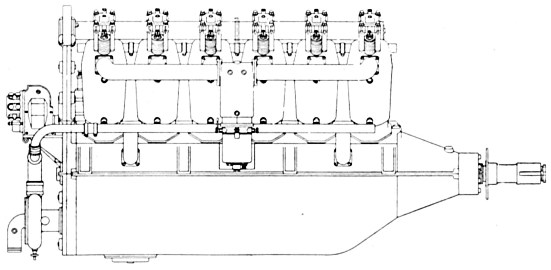
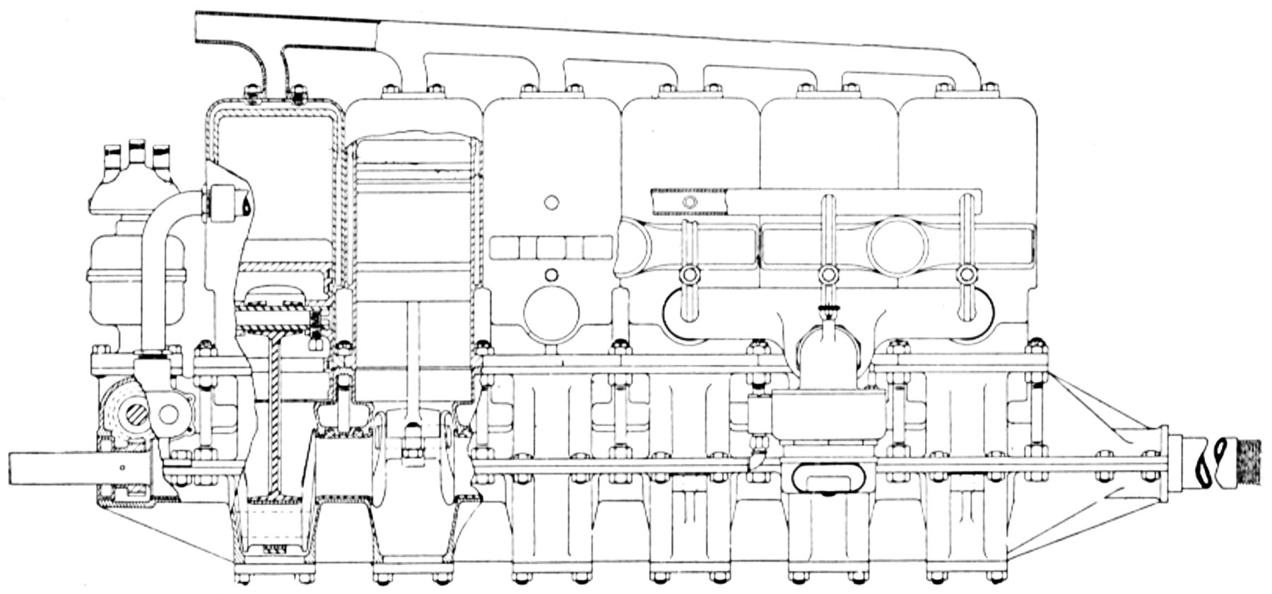
The Rp III was a 1914 water-cooled vertical six based on the Rapp 100 hp cylinder construction. With a 140 mm (5.512") bore, 160 mm (6.299") stroke and 14.778 l (901.81 in³) displacement, the initial version was rated 125 hp and weighed 215 kg (474 lb). Further development produced a version producing 150 hp at 1,350 rpm and weighing 260 kg (573 lb). Fuel and oil consumption were 0.485 ‑ 0.507 and 0.044 lb/hp/hr. The overhead camshaft was driven by a vertical shaft situated between cylinder #4 and #5. A gear pump circulated the oil and an eccentric pump introduced fresh oil into the system. The camshaft employed felt ring lubrication, the cams were greased, and the springs and rollers oiled. The magnetos were arranged crosswise between the cylinders and driven from the vertical drive shaft. Carburetors were placed at the engine aft. While the peculiar camshaft/magneto drive arrangement separated the magnetos from the pilot's magnetic compass, the extra spacing between cylinders four and five also resulted in an linearly asymmetric crankshaft that induced vibration and reduced reliability.
The Rp IIIa, an improved vertical six with the same bore, stroke and displacement but with a 4.63:1 compression ratio, appeared in 1916. This engine was rated 175 hp, but produced only 162 hp at 1,400 rpm and 166 hp at 1,500 rpm. At 1,400 rpm fuel and oil consumptions were 0.595 and 0.0325 lb/hp/hr. Dry weight was 295 kg (651 lb). The inlet valves opened 2° early and closed 50° late; the exhaust valves opened 51° early and closed 1° late. Inlet valve lift was 10.4 mm (0.409") and exhaust valve lift was 9.3 mm (0.367"). Carburetors were placed on the engine left. Although this engine had a higher rated power, its design failed to address some of the fundamental flaws of its predecessor.
Two of these six-cylinder banks were used to create a 60° V-12 rated 300 hp at 1,350 – 1,400 rpm and weighing 470 ‑ 474 kg (1,036 – 1045 lb). Some variants had exhausts on the outside while others had the exhausts within the Vee and used exterior Pallas carburetors.
 |
 |
| Rp IV (A39) | |
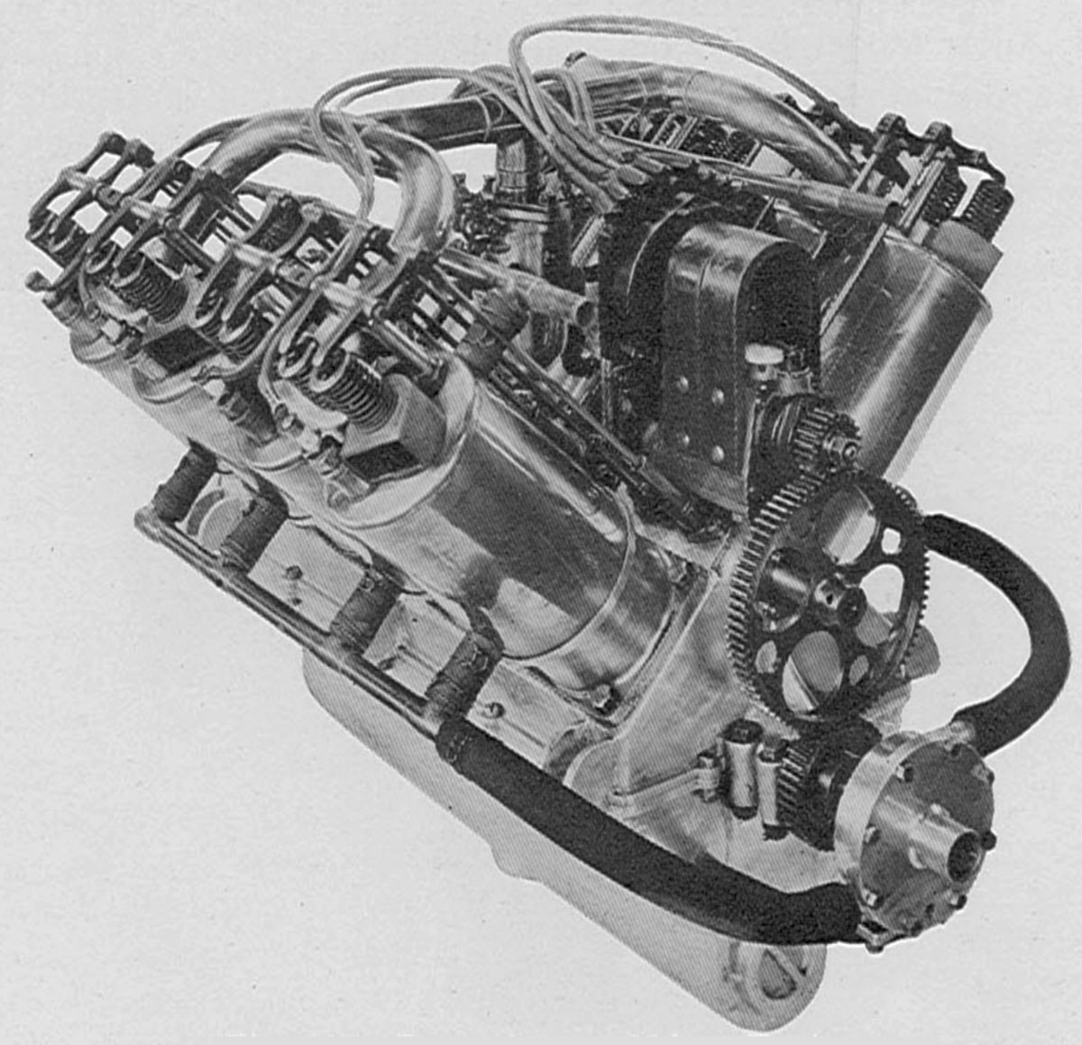
The Rp IV was a completely redesigned vertical six introduced later in 1916. This engine featured four valves per cylinder and was probably a higher power class, but little is know about this engine, except that it also failed to gain any commercial success, further tarnishing Rapp's reputation.
Using Auspitzer's money, Rapp Motorenwerke expanded rapidly, employing 370 workers by 1915. Several aircraft prototypes were designed but all were unsuccessful because of design weaknesses. Despite its failed prototypes, at the beginning of WWI, Rapp Motorenwerke was a key Bavarian war effort provider. The Prussian Army Administration rejected Rapp engines as unsuitable, but the Bavarian Army Administration and the Imperial Naval Office of the Imperial Austro-Hungarian Army Administration continued to order Rapp engines licensed through Austro-Daimler.
The Prussian Army Administration ordered 600 innovative high-altitude engines designed by Max Friz; these were eventually to be designated BMW IIIa. This deal resulted in reorganization of Rapp Motorenwerke's legal structure, leading to Karl Rapp's resignation. Rapp-Motorenwerke became Bayerische Motoren Werke GmbH (BMW) in 1917.
References
Angle, Glenn D, ed. Aerosphere 1939 (New York, New York: Aircraft Publications, 1940).
Anble, Glenn D, ed. Airplane Engine Encyclopedia (Dayton, Ohio: Otterbein Press, 1921).
Image Sources: A39 = Aerosphere 1939; AEE = Airplane Engine Encyclopedia; Flt = Flight Magazine; NARA = U.S. National Archives and Records Administration; UKNA = United Kingdom National Archives; WC = Wikimedia Commons.
Rausenberger
Rausenberger aircraft engines were designed by Larence Elson Rausenberger (1887-1980). Early models were built by the Dayton Aero Motors Company of Dayton, Ohio. The later Rausie E-6 was built by the Steel Products Engineering Company of Springfield, Ohio.
The A-8, Rausenberger first design, was a water-cooled 90° V-8 built during 1910. With a 3.5" (88.9 mm) bore and 3.75" (95.25 mm) stroke, it displaced 288.63 in³ (4.73 l), produced 45 hp at 1,350 rpm and weighed complete 275 lb (124.7 kg). Lubrication was by gravity and splash. A Schebler Model L carburetor with a 1.25" venturi furnished the mixture, and a Bosch DR-8 magneto supplied ignition.
The B-8, a water-cooled 90° V-8 produced during 1911 and 1912, had a 4.125" (104.78 mm) bore, 4.75" (120.65 mm) stroke, displaced 507.83 in³ (8.32 l), was rated 75 hp at 1,350 rpm and weighed 287 lb (130.2 kg). The individual cast iron cylinders were with copper water jackets. The valves seated vertically in the cylinder head and were operated by push rods and rocker arms. The inlet valves opened 10° late and closed 25° late; the exhaust valves opened 15° early and closed 7° late. A plunger oil pump provided pressure lubrication. A Schebler Model L carburetor with a 1.75" venturi was situated in the Vee and supplied all cylinders. A Bosch DR-8 magneto furnished ignition.
The C-12, a water-cooled 60° V-12 produced during 1914 and 1915, had a 4.125" (104.78 mm) bore, 6.00" (152.40 mm) stroke, displaced 962.21 in³ (15.77 l), was rated 150 hp at 1,350 rpm and weighed 590 lb (267.6 kg). It was 70" long and 24" wide. The individual cast iron cylinders had spun copper water jackets. The valve ports were not jacketed. The vertical 2.0" (50.8 mm) diameter valves were lifted 0.3125"(7.94 mm) by push rods and rocker arms from a camshaft in the Vee. Valve timing was the same as in the B-8. The six-throw crankshaft was mounted in seven plain bearings. The H-section connecting rods ran side-by-side on the crankpins. The pistons were cast from grey iron and fitted with three double rings. A plunger pump provided pressure lubrication using oil from a reservoir in the lower aluminum crankcase half with sufficient capacity for five hours operation. Cooling water was circulated by a centrifugal pump driven from the crankshaft end. The engine was available with Splitdorf twelve-cylinder magneto for dual ignition or a Bosch DR-6 magneto for single ignition.
The 1916 C-12 engine had new cylinders and a new induction system. The copper water jackets now entirely covered the cylinder head, including the inlet and exhaust ports. Two duplex Zenith carburetors, situated in the Vee, supplied the cylinders in groups of three. The fuel consumption was said to have been 0.58 lb/hp/hr.
The D-12, designed in 1917, was a water-cooled 60° V-12 with a 5.000" (127 mm) bore, 6.500" (165.1 mm) stroke, and 1,531.53 in³ (25.10 l) displacement and 4.76:1 compression ratio. It was rated 250 hp at 1,300 rpm and 325 hp at 1,600 rpm. Fuel and oil consumptions were 0.52 and 0.03 lb/hp/hr and the dry weight was 825 lb (374.2 kg). The cylinders were machined from steel forgings and encased in sheet-steel water jackets that were welded in place. The inclined valves were operated from an overhead camshaft through rocker arms. This overhead camshaft was mounted in seven bearings and driven by a spur gear train. The six-throw crankshaft was mounted in seven bearings, with an extra hearing its the crankcase extension at the propeller end. The fork-and-blade connecting rods attached aluminum alloy pistons. A gear pump maintained pressure lubrication and two duplex Zenith carburetors exterior to the cylinder banks furnished the mixture.
 |
 |
 |
 |
 |
| A-8 | C-12, Early | C-12, 1916 | D-12 | |
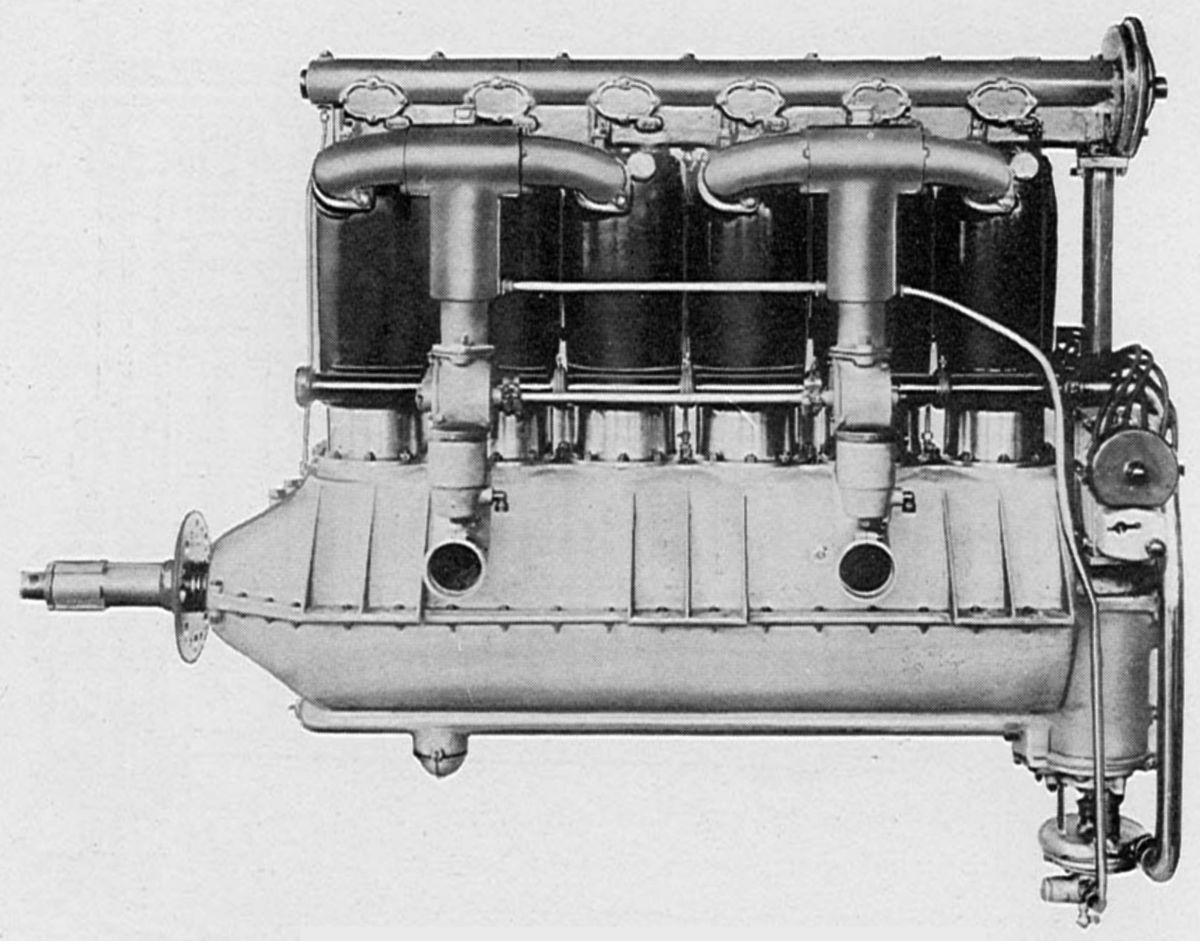
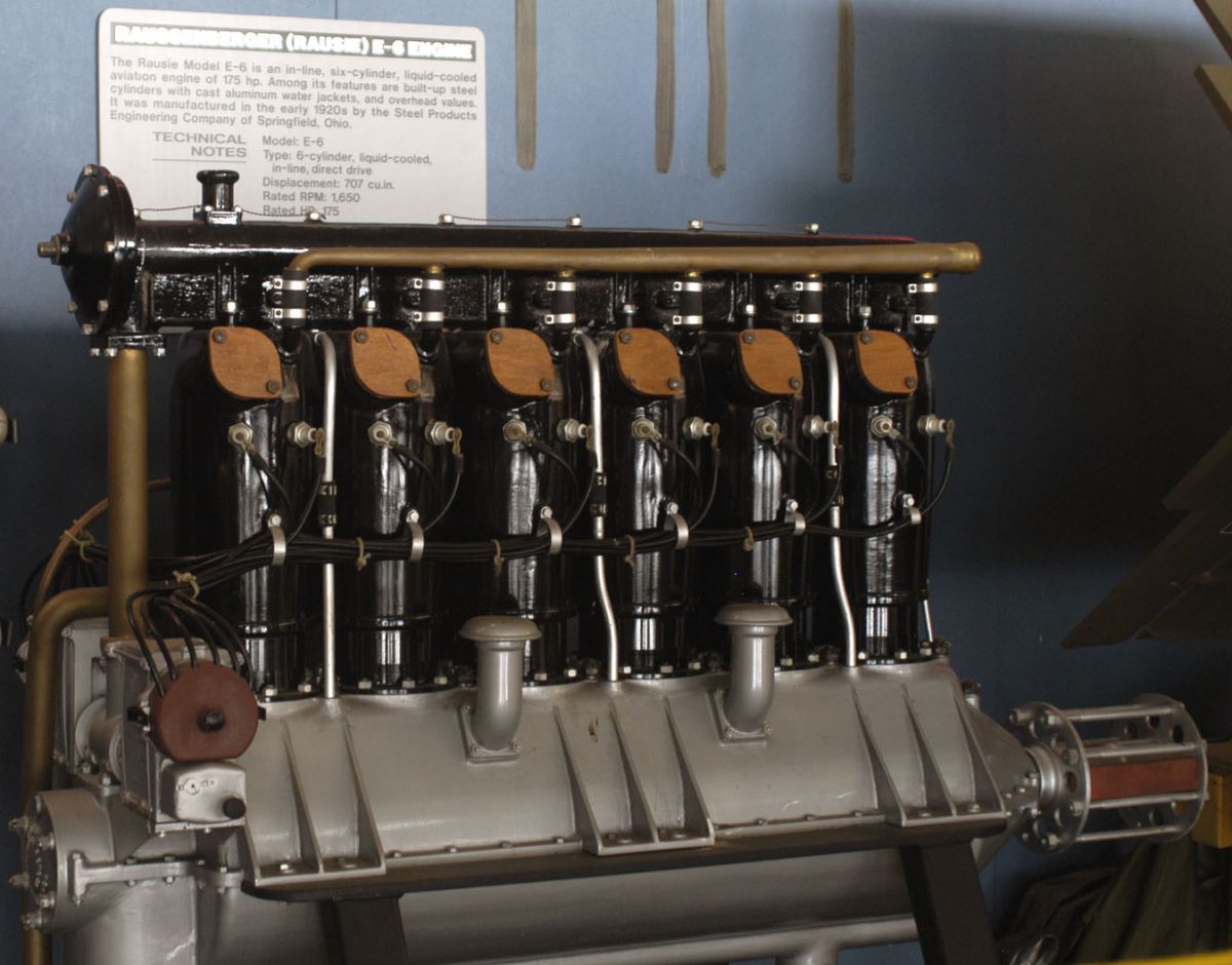
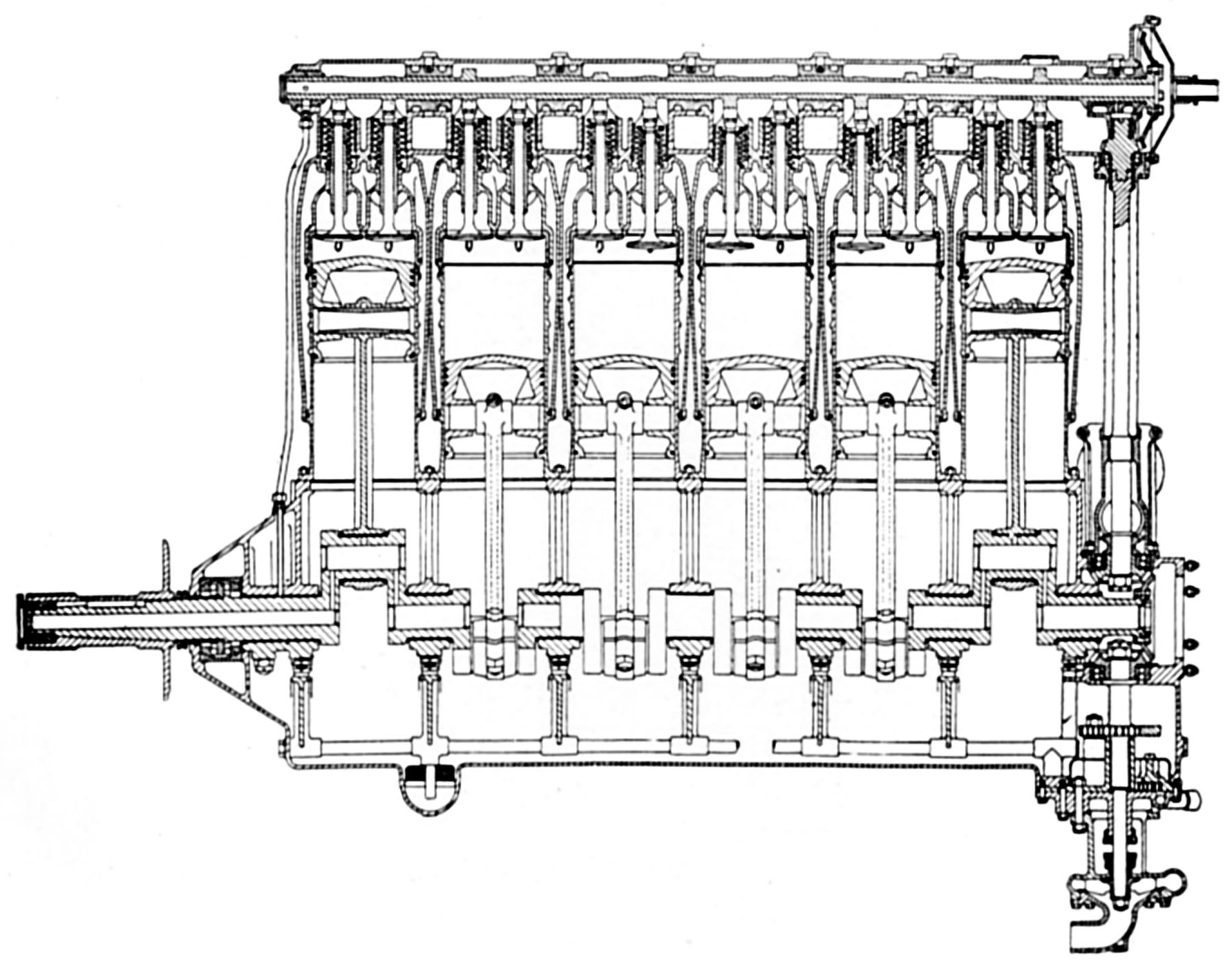
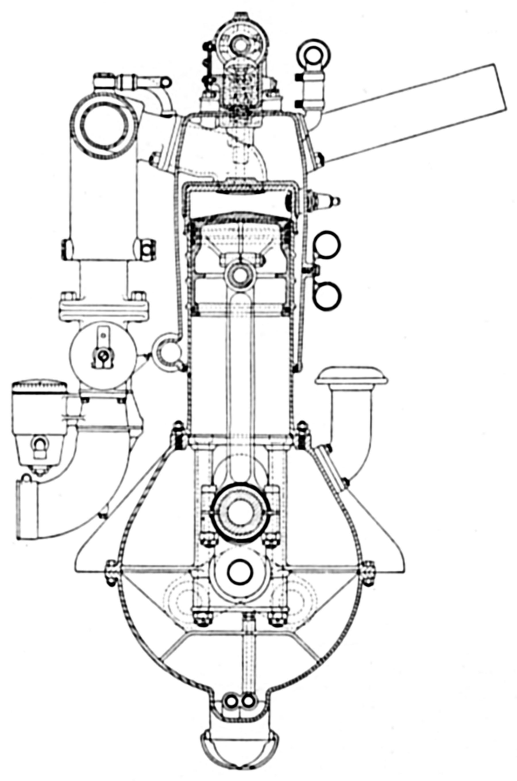
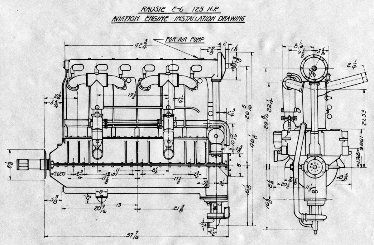
The 1920 Rausie E-6 was a water-cooled vertical six with a 5.000" bore, 6.000" stroke, 706.86 in³ (11.583 l) displacement and 5.5:1 compression ratio. It was rated 175 hp at 1,650 rpm and weighed 510 lb (231.3 kg). It was 51" (1,295 mm) long, 21.75" (552 mm) wide and 47" (1,194 mm) high. The separate cylinders were formed from a steel barrel screwed and welded into a steel combustion chamber, all enclosed by an aluminum water jacket screwed tightly to the head against a copper asbestos gasket and packed at the lower end by a rubber ring. The valves stood vertically in the cylinder head along the engine center line and were operated directly from the cams by plungers guided in the camshaft housing (see U.S. Patent 1,401,442). The clear diameter of each valve was 2.5" (63.5 mm), and the lift was 0.5" (12.7 mm). The inlet valves opened 10° late and closed 40° late, the exhaust opened 48° early and closed 15° late. The six-throw crankshaft had seven main bearings, the connecting rods had H-section shanks, and the aluminum pistons had three top rings and a lower oil-scraper ring. Gear pumps forced oil to the bearings and scavenged the sump. Cooling water was circulated by a centrifugal pump. Each of the two Miller carburetors supplied three cylinders, and two Dixie 600 magnetos furnished dual ignition.
 |
 |
 |
 |
 |
| (AEE) | (NMUSAF) | (AEE) | (NARA) | |
Renard
During 1925, Alfred Renard (21 Apr 1895 ‑ 20 Jun 1988), a Belgian aviator and engineer, established The Société Anonyme des Aviens et Moteurs Renard in Brussels, Belgium to design and produce aircraft engines. In 1929, the Wright-Tuttle Aircraft Motors Corporation of Anderson, Indiana acquired the exclusive rights to manufacture and distribute these engines in the United States, Mexico and Cuba. Very few, if any, were ever built. Renard apparently ceased activities sometime during 1934.
 |
 |
 |
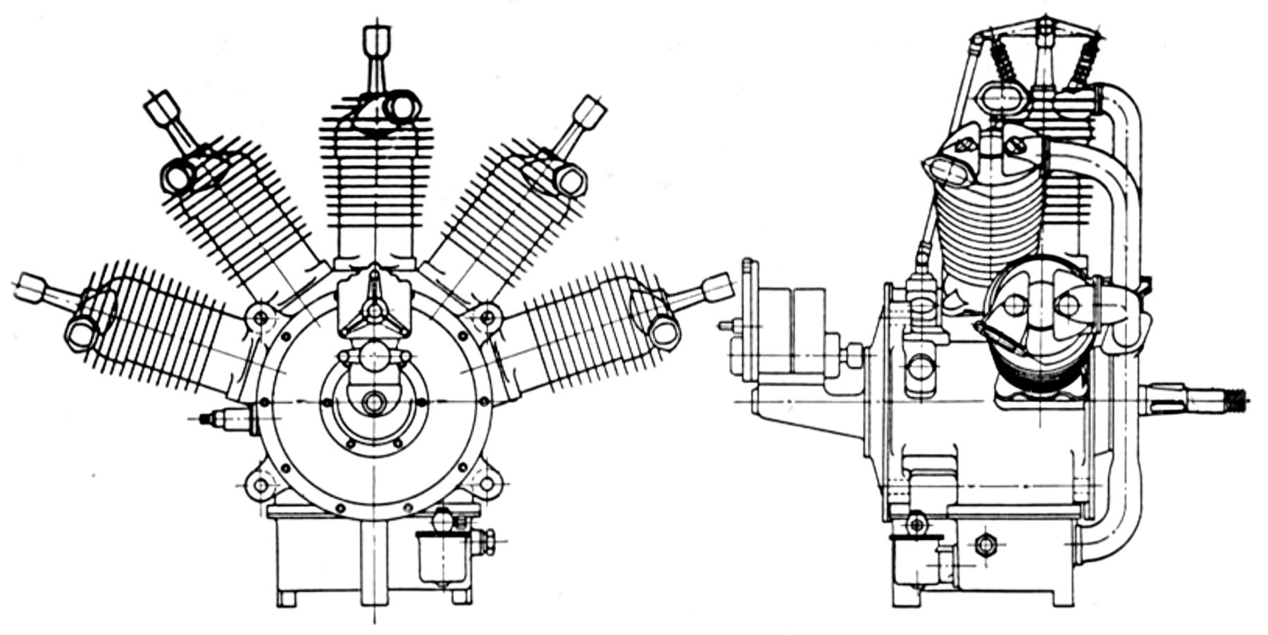
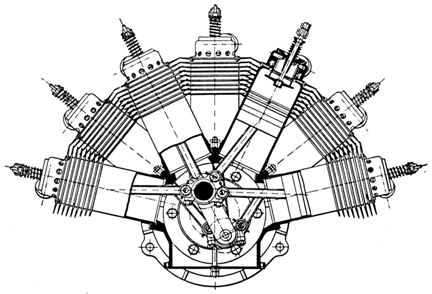
| Type 100 (A39) | ||
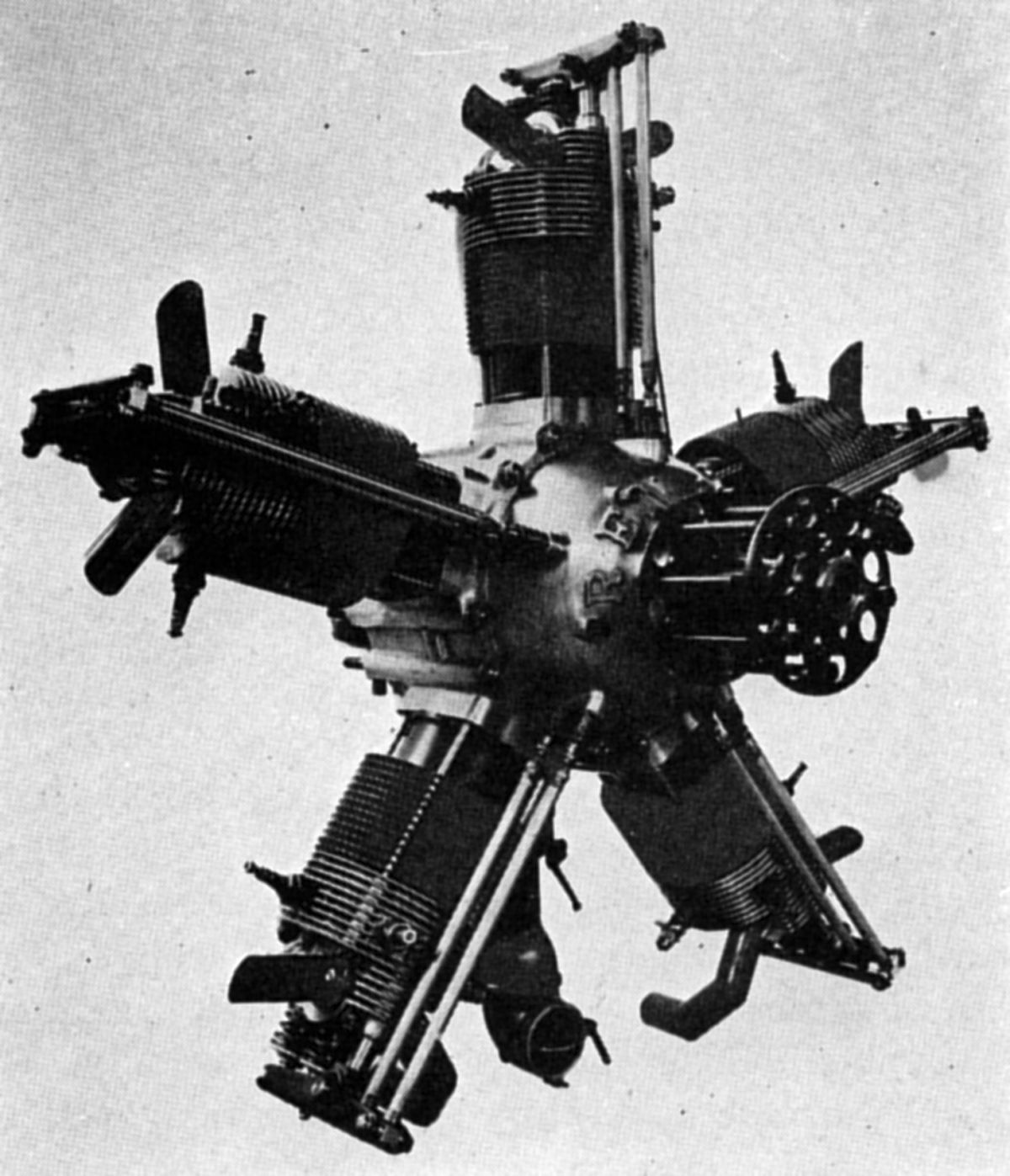
The Type 100 was an air-cooled five-cylinder radial with a 120 mm (4.724" ) bore, 140 mm (5.512") stroke, 7.917 l (483.11 in³) displacement and 5.2:1 compression ratio. Producing 120 hp at 1,580 rpm and 145 hp at 1,750 rpm, it weighed 124.74 kg (275 lb), was 1,080 mm (42.5") in diameter and 597 mm (23.5") long. Fuel and oil consumptions were 0.503 and 0.022 lb/hp/hr. The forged cylinder barrels were machined all over with integral cooling fins. The die-cast aluminum-alloy cylinder heads were fastened by four studs extending from the crankcase. The spark plugs seated on bronze inserts. Two vertical overhead valves in each cylinder seated on forged aluminum-bronze inserts, and were operated by duralumin tubing push rods and forged steel rocker arms running on ball bearings. Two cam rings were attached via ball bearings to a spur gear on an eccentric keyed to the crankshaft. This spur gear engaged an internally-toothed ring fixed to the crankcase. The cam rings were provided with cylindrical rollers that directly operated the tappets instead of normal cams. The connecting rod assembly was a unique articulated system in which all rods had tubular shanks. The master rod big end was split and the halves were held together by steel plates that threaded over the crank, engaged with circular shoulders on the big-end faces. The plates, held in place by bolts paralleling the crankshaft axis, also retained the link rod knuckle pins. The rods had bronze bushings, and the piston pins floated in both the rods and aluminum-alloy pistons. The one-piece crankshaft ran on two roller bearings, and a double ball-thrust bearing at the forward end carried propeller thrust loads. The aluminum crankcase was split in the cylinder plane and held together by two through bolts between adjacent cylinders. These bolts extended through the rear face and were used for mounting the engine. The crankcase front half carried the cam mechanism, and this was closed by a cover that supported the thrust bearing. The rear half contained the induction passages, and supported a case that carried the magnetos and oil pumps. The two Scintilla magnetos were mounted parallel to the engine axis. Between them and below the central axis was a shaft driving the oil pump. There was provision for fitting a gas-starter distributor and hand-starting magneto. The gear-type oil pump consisted of pressure and scavenging sections for dry-sump lubrication.
 |
 |
| Type 200 (A39) | |
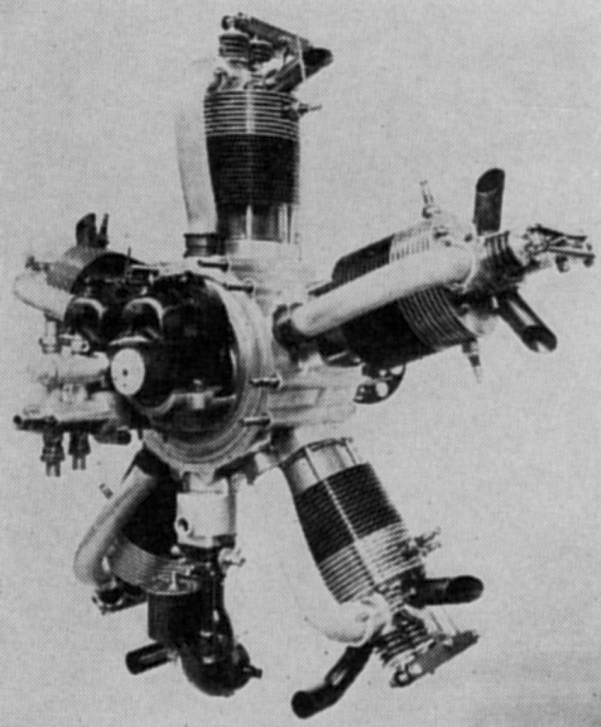
The Type 200 was a nine-cylinder version of the Type 100 and was almost identical in construction. It displaced 14.250 l (869.6 in³) and weighed 201.85 kg (445 lb). It produced 200 hp at 1,600 rpm and 220 hp at 1,750 rpm.
The Type 400, under development during 1933, was an air-cooled 18-cylinder two-row radial engine with a 120 mm (4.724" ) bore, 150 mm (5.906") stroke, 30.536 l (1,863.44 in³) displacement and 6.0:1 compression ratio. It was rated 495 hp at 1,800 rpm, weighed 359.25 kg (792 lb), was 1,140 mm (44.9") in diameter and 1,086 mm (42.75") long.
Renault (link)
R.E.P.
Robert Albert Charles Esnault-Pelterie (8 Nov 1881 ‑ 6 Dec 1957) was a French aircraft/engine designer and visionary. Born into privilege, he was a trained engineer whose fertile mind produced numerous innovations. He invented the equivalent of ailerons after discarding the Wright Brothers' wing-warping scheme for his 1906 airplane design. His first powered flight in 1908 used an engine of his own design. He patented the joystick flight control scheme. In 1913 he independently derived Tsiolkovsky's rocket equation. He envisioned space travel and suggested nuclear power to bridge interplanetary distances. He proposed ballistic missiles that carried warheads and experimented with chemical propellants.[Wiki]
 |
 |
 |
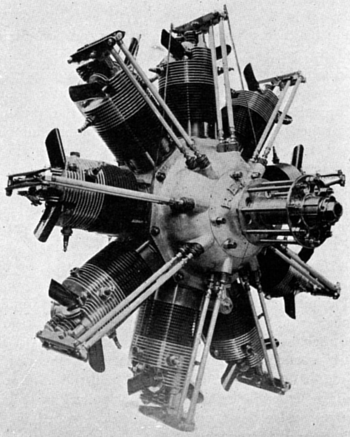
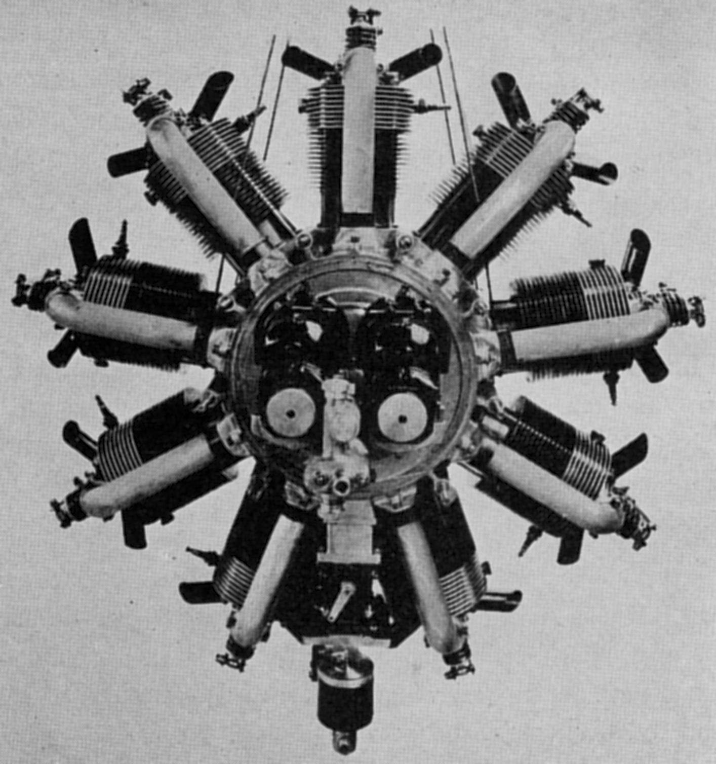
| R.E.P. Five-Cylinder (AEE) | R.E.P. Seven-Cylinder (AEE) | |
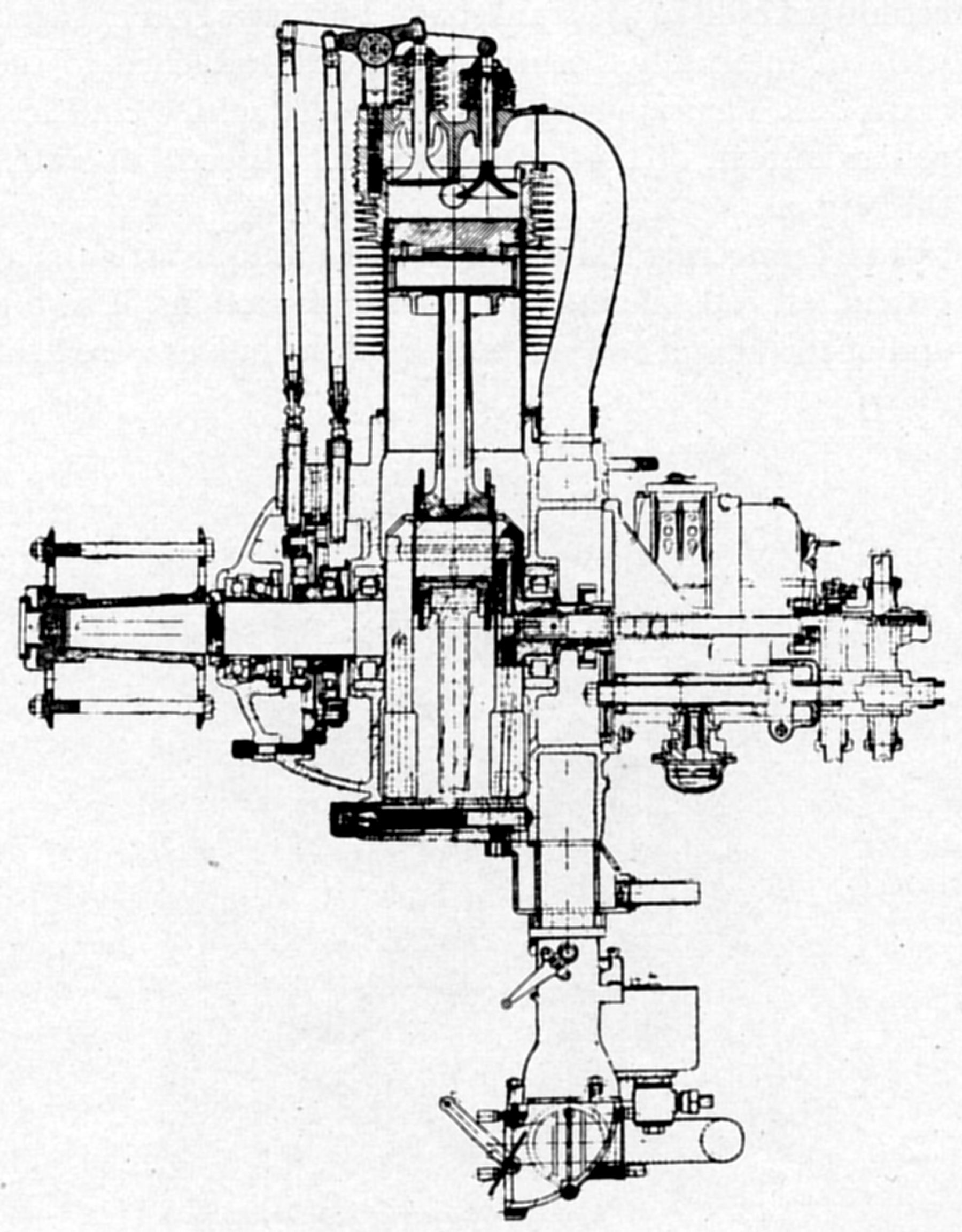
Pelterie began manufacturing air-cooled engines in France during 1908, selling them under the name R.E.P. Most were air-cooled fan types. Like the Anzani designs, both valves were operated by one rocker arm. The cam plate had a face groove in which ran rollers attached to the valve tappet sides. This plate rotated opposite the crankshaft direction and the groove pushed and pulled a rocker alternately. Mixture was supplied to each cylinder by a pipe connected to an annular chamber surrounding the crankcase rear.
A five-cylinder engine with an 85 mm (3.347") bore, 95 mm (3.740") stroke and 2.795 l (164.48 in³) displacement was rated 20 hp at 1,400 rpm. Its cast iron cylinders had integral cooling fins. Weight was 37.4 kg (82.5 lb).
A seven-cylinder engine with the same cylinder dimensions displacing 3.774 l (230.28 in³) was rated 30 hp at 1,400 rpm and weighed 52 kg (114.5 lb). Four cylinders were forward and three aft, each with articulated connecting rod assemblies attached to a two-throw crankshaft.
A ten-cylinder fan type engine, a doubled 20-hp model, displaced 5.391 l (328.97 in³) and was rated 40 hp at 1,400 rpm. A two-throw crankshaft was used, as were dual magnetos and carburetors. Weight was 72 kg (158.5 lb).
A fourteen cylinder doubled 30-hp model displacing 7.547 l (460.55 in³) was rated 60 hp at 1,400 rpm and weigh 98 kg (216 1b).
R.E.P. also built a five-cylinder fan engine with a 100 mm (3.937") bore and 140 mm (5.512") stroke that displaced 5.498 l (335.50 in³) that produced 50hp, and another five-cylinder fan engine with a 110 mm (4.331") bore, 160 mm (6.299") stroke and 7.603 l (463.94 in³) that produced 60 hp.
A later R.E.P. air-cooled radial seven with a 110 mm (4.331") bore, 160 mm (6.299") stroke and 10.644 l (649.52 in³) displacement was rated 95 hp at 1,100 rpm and weighed 209.5 kg (462 lb).
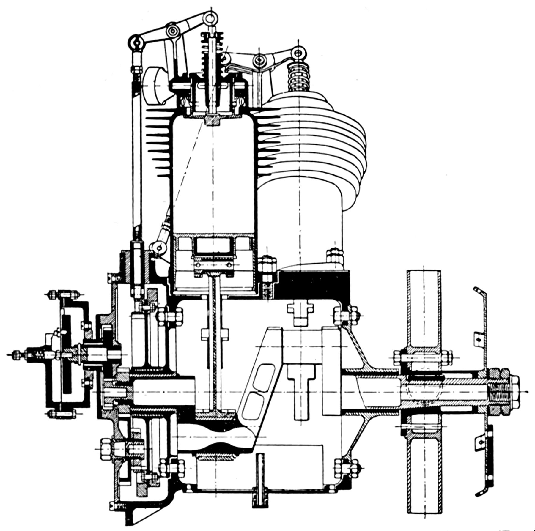
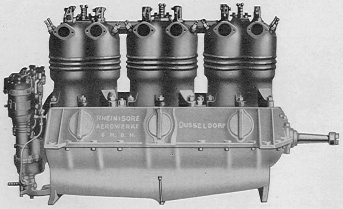
Rheinische
Rheinische Aero Works of Euskirchen, Germany, built water-cooled vertical engines with a 120 mm (4.724") bores and 140 mm (5.512") strokes. The cylinders had welded-on sheet-metal water jackets and overhead valves operated by push rods and rocker arms. Two Bosch magnetos supplied dual ignition and a Bosch electric starter was fitted. Wet-sump pressure lubrication was featured.
 |
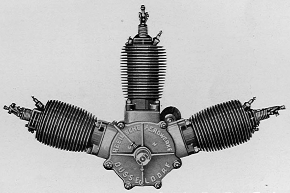 |
| Rheinische 100 hp (AEE) | Rheinische 35 hp (AEE) |
The vertical four, displacing 6.333 l (386.49 in³), was rated 70 hp at 1,250 and weighed 127 kg (280 lb).
The vertical six, displacing 9.500 l (579.74 in³), was rated 100 hp at 1,250 rpm and weighed 188 kg (415 lb).
An air-cooled three-cylinder fan engine with a 105 mm (4.134") bore, 130 mm (5.118") stroke and 3.377 l (206.08 in³) displacement was rated 35 hp at 1,350 rpm and weighed 45 kg (99 lb). During 1920, a similar 20 hp engine for light aircraft was built.
An air-cooled radial five with a 105 mm (4.134") bore, 130 mm (5.118") stroke and 5.628 l (343.46 in³) displacement developed 58 hp at 1,350 rpm and weighed 95 kg (210 lb). The valves were operated by a three-cam disc, push rods and rocker arms; the exhaust valves were in front. Oil entered the hollow crankshaft, lubricated the crankpin bearing and then the piston pins through hollow connecting rods. A separate pressure line supplied the rear bearing. Inlet pipes carried the mixture from a ring-shaped induction passage in the crankcase rear.
An air-cooled horizontally-opposed two-cylinder 20 hp light plane engine was produced about 1922.
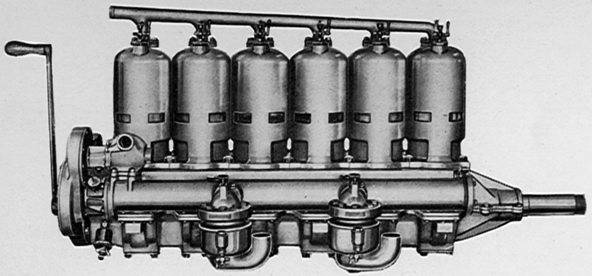
Roberts
Edmund Willson Roberts (1866 – 14 Mar 1947) studied engineering at Cornell University and served as an assistant to Hiram Maxim in England, who on 31 Jul 1894, flew a short distance in a steam-powered airplane. Roberts wrote a textbook on engine design for International Correspondence Schools, became an automotive mechanical engineer for Elmore Manufacturing Company, and established the Roberts Motor Company in Sandusky, Ohio, which manufactured engines for boats and airplanes until 1914. During 1918 and 1919, he served as a consulting engineer for the National Advisory Committee for Aeronautics in Washington. Roberts designed a total of 131 engines in his life. [Rutherford B. Hayes Presidential Library]
All Roberts airplane engines were water-cooled vertical two-strokes. One of the first, built during 1911 – 1912, was a four-cylinder with a 4.500" (114.3 mm) bore, 5.000" (127 mm) stroke and 318.09 in³ (5.213 l) displacement that produced 50 hp at 1,400 rpm and weighed 170 lb (77 kg). Length was 40.5" (1,029 mm), width 24.0" (610 mm) and height was 25" (635 mm). The cylinders were cast from Aerolite (86% Al, 12% Cu, 2% Mn). The water jacket was partly cored from the casting and the remainder covered by an aluminum jacket caulked into grooves in the cylinder (US 1,210,537). The three-port cylinders featured a spiral tubular rotary valve instead of ports uncovered by the piston. A cellular bypass (US 1,101,332) prevented back firing or crankcase explosions. The pistons and rings were made from cast iron. A Bosch magneto with a helical gear for turning the armature to advance and retard the spark provided ignition. A Kingston carburetor supplied the mixture, and lubrication was by splash.
A six-cylinder with the same bore and stroke displaced 477.13 in³ (7.82 l), produced 75 hp and weighed 213 lb (97 kg). Length was 52.5" (1,334 mm), width 24.0" (610 mm) and height was 25" (635 mm).
 |
 |
 |
| Roberts 75 hp Two Stroke (AEE) | Roberts 100 hp Two Stroke (AEE) | |
The Model 6X was a six-cylinder with a 5.000" (127 mm) bore, 5.000" (127 mm) stroke and 589.05 in³ (9.653 l) displacement that developed 100 hp at 1,200 rpm and weighed 350 lb (159 kg). Fuel and oil consumptions were 0.63 and 0.047 lb/hp/hr. The separate cylinders with integral water jackets were cast from grey iron . The aluminum alloy pistons were fitted with two rings above the piston pin and one below. The crankshaft was supported in seven plain hearings, and the connecting rods had H-section shanks of . Two 2" Panhard carburetors supplied three cylinders each, and the ignition was by either one or two Bosch magnetos.
A Roberts six-cylinder with a 5.000" (127 mm) bore, 5.500" (139.7 mm) stroke and 647.95 in³ (10.618 l) was rated 100 hp at 1,200 rpm and weighed 368 lb (167 kg).
The Model 6XX, another six-cylinder with a 6.500" (165.1 mm) bore, 6.000" (152.4 mm) stroke and 1194.59 in³ (19.576 l) displacement was rated 200 hp at 1,400 rpm. Fuel and oil consumptions were 0.63 and 0.047 lb/hp/hr. Weight was 690 lb (313 kg).
The Model E-12, a V-12 with a 6.000" (152.4 mm) bore, 6.500" (165.1 mm) stroke and 2,205.40 in³ (36.140 l) displacement was rated 350 hp at 1,200 rpm and weighed 990 lb (449 kg). The crankshaft had thirteen bearings.
Send mail to
![]() with questions or comments about this web site.
with questions or comments about this web site.
![]()