L.jpg)
R.jpg)
Selected Early Engines
Manly, Maximotor, Maybach, Mercedes, Michel, Michigan Aero, Miller, Minerva, Morehouse, Murray-Willat
Compiled by Kimble D. McCutcheon
Published 17 Oct 2022; Revised 6 Nov 2022
Mercedes
The Daimler-Motoren-Gesellschaft of Stuttgart, Germany was one of the first firms to build internal combustion engines and also among the first to introduce aircraft engine designs. Formed in 1890 by Gottlieb Daimler, who had developed his famous high-speed engines at Cannstatt, where he had settled after serving as technical manager for the firm Otto and Langen from 1872 to 1882. Dr. Nicolaus August Otto is credited inventing and building a four-stroke/cycle internal combustion engine in 1876. Mercedes was the name given the motor car built by Daimler-Motoren-Gesellschaft from 1901 on, and this name also was adopted for the marine and aircraft engines. Daimler granted licenses to associate firms in other countries.
The first Daimler aircraft engine propelled the first recorded ascent of Dr. Friedrich Hermann Wölfert's airship on 1 Sep 1888; it was a single-cylinder that produced 2 hp. Later, in the early 1890s, a two-cylinder 6 hp engine was used. Both engines had tube ignition and aluminum crankcases. Dr. Wölfert was killed on 14 Jun 1897 in an accident resulting from a fire that occurred on a trial flight in Berlin. The rigid airship designed and constructed by an Hungarian engineer, David Schwarz, flew on 3 Nov 1897, and was powered by a Daimler four-cylinder 10 hp gasoline engine. Two four-cylinder Daimler engines of 12 hp and using make-and-break ignition were used in 1900 for the first rigid airships built by Count Ferdinand von Zeppelin. A four-cylinder Mercedes engine rated at 35 hp was installed in the first airship launched by the Lebaudy Brothers of Paris in 1901.
A 90-hp four-cylinder Mercedes engine powered the Parseval I, a non-rigid German airship launched 1906. Another 60-hp four-cylinder Mercedes engine was installed in the German airship designed and built under Major Hans Georg Friedrich Groß's supervision in 1908. The Zeppelin II, launched in 1905, used two 90-hp four-cylinder Mercedes engines. The 120-hp Mercedes engines powered the Zeppelin IV of 1909, and a similar engine was installed in the Parseval II. These engines had Bosch high-tension magneto ignition. The No. V Zeppelin ship, built by in 1910, carried three four-cylinder 120/150 hp Mercedes engines. The famous Schütte-Lanz rigid airship employed a wooden framework and was powered by an eight-cylinder Mercedes engine rated 240 hp.
Water-cooled Mercedes engines designed purely for aircraft purposes appeared in 1909. An inline four had a 110 mm (4.331") bore, 140 mm (5.512") stroke and 5.322 l (324.77 in³) displacement. Its overhead valves were operated by push rods and rocker arms, and the timing gears were not enclosed. A similar inline four with a 110 mm (4.331") bore, 140 mm (5.512") stroke and 5.322 l (324.77 in³) displacement produced 57 hp at 1,200 rpm and used an overhead camshaft. Another inline six with a 105 mm (4.134") bore, 140 mm (5.512") stroke and 7.274 l (443.86 in³) displacement developed 80 hp at 1,200 rpm. It weighed 142 kg (312 lb).
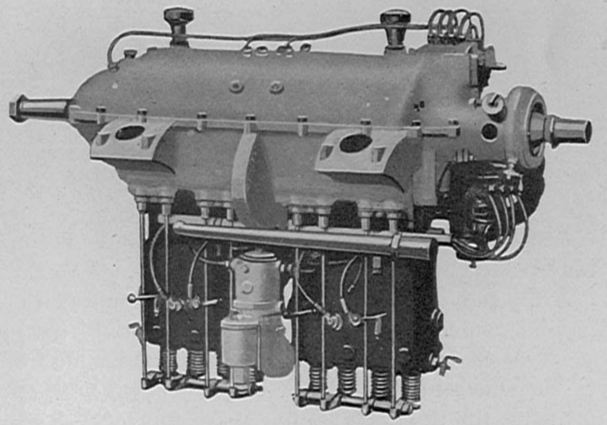
The Type F1244 (also E4F) was an inline four with a 120 mm (4.724") bore, 140 mm (5.512") stroke and a 6.333 l (386.46 in³) displacement. It was rated at 70 hp at 1,350 rpm, with 0.53 and 0.033 lb/hp/hr fuel and oil consumptions. Weight was 140 kg (308 lb). Originally the cylinders were cast in pairs from grey iron with water jackets integral. Later the jackets were made separately from sheet steel and welded in place. The connecting rods had H-section shanks and the pistons were pressed steel. Bosch magnetos provided dual ignition.
A similar inline four with a 140 mm (5.5112") bore, 150 mm (5.906") stroke and 9.236 l (563.63 in³) displacement developed 90 hp at 1,200 rpm and 100 hp at 1,400 rpm. Fuel consumption was 0.49 lb/hp/hr and weight was 181 kg (400 lb).
|
|
| E6F, D.I (AEE) | |
The 1913 E6F (D.I) with its 120 mm (4.724") bore and 140 mm (5.512") stroke displaced 9.5 l (579.73 in³) and weighed 202 kg (445 lb). It was rated 100 hp. Fuel and oil consumptions were 0.53 and 0.33 lb/hp/hr.
The Type F1454, an inline four with a 140 mm (5.512") bore, 150 mm (5.906") stroke and 9.236 l (563.62 in³) displacement, developed 90 hp at 1,200 rpm with a 0.49 lb/hp/hr fuel consumption. Weight was 165 kg (363 lb).
The J4L, an inline four with a 160 mm (6.299") bore, 170 mm (6.693") stroke and 13.672 l (834.33 in³) displacement was rated 120 hp at 1,100 rpm and weighed 299 kg (660 lb). The iron cylinders were cast in pairs and had one inlet and two exhaust valves, all parallel with the cylinder axes, that were operated via push rods and rocker arms.
An inline four with a 175 mm (6.890") bore, 165 mm (6.496") stroke and 15.875 l (968.75 in³) displacement developed 137 hp at 1,100 rpm. Weighing 367 kg (810 lb), it was intended for dirigible use and was furnished to Zeppelin, Parseval and Siemens-Schuckert.
 |
| Inverted Four (AEE) |
An inverted inline four with Type F1244 cylinders was built to provide increased pilot visibility. This engine developed 70 hp at 1,400 rpm. The inverted cylinders admitted cooling water directly into the cylinder head, which was the hottest cylinder part.
The J8L, an inline eight airship engine using eight J4L cylinders with 160 mm (6.299") bores, 170 mm (6.693") strokes and 27.344 l (1,668.66 in³) displacement was rated 240 hp at 1,100 rpm. It weighed 567 kg (1,250 lb).
Another inline eight with a 175 mm (6.890") bore, 165 mm (6.496") stroke displacing 31.750 l (1,937.49 in³) developed 240 hp at 1,100 rpm. Intended for dirigible use, it weighed 826 kg (1820 lb).
An inline six with a 160 mm (6.299") bore, 170 mm (6.693") stroke and 20.508 l (1,151.48 in³) displacement delivered 200 hp at 1,250 rpm and weighed 425 kg (937 lb). Four were supplied to Luftschiffbau Schütte-Lanz, a company that built an airship series from 1909 until 1917.
In 1916 an inline eight with a 106 mm (4.173") bore, 170 mm (6.693") stroke and 12.002 l (732.41 in³) developing 185 hp at 1,800 rpm was built for Schütte-Lanz.
An inline eight with a 175 mm (6.890") bore, 165 mm (6.496") stroke and 31.750 l (1,937.50 in³) displacement was rated 240 hp at 1,100 rpm and weighed 826 kg (1820 lb). This engine was primarily intended for dirigibles as two were built for Schütte-Lanz.
The Type F10546 was an inline six built in 1912 for the Kaiserpreis für den besten deutschen Flugzeugmotor (Emperor's Prize for the best German aircraft engine). With a 105 mm (4.134") bore, 140 mm (5.512") stroke and a 7.274 l (443.89 in³) displacement, it developed 90 hp at 1,100 and weighed 142 kg (312 lb). Fuel consumption was 0.505 lb/hp/hr. This engine won second place.
The Type F1246, an inline six with a 120 mm (4.724") bore, 140 mm (5.512") stroke and 9.500 l (579.73 in³) displacement, was rated at 100 hp and weighed 201 kg (444 lb). Fuel and oil consumptions were 0.53 and 0.033 lb/hp/hr.
 |
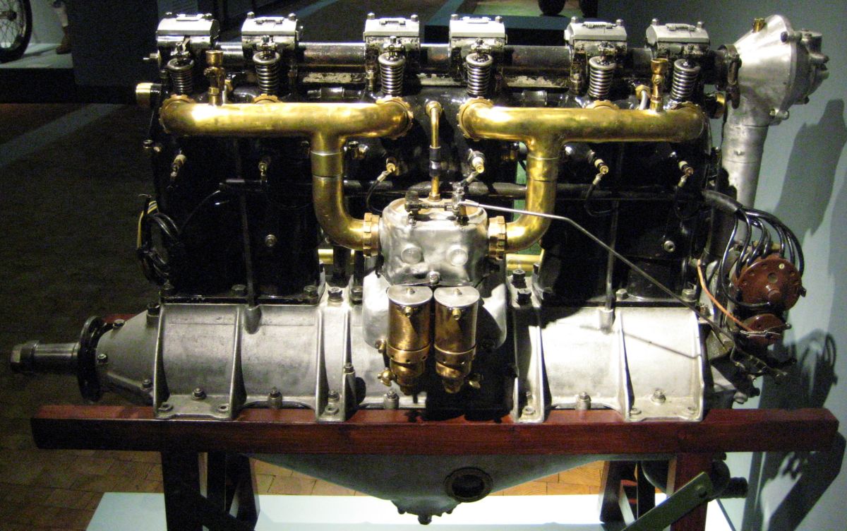 |
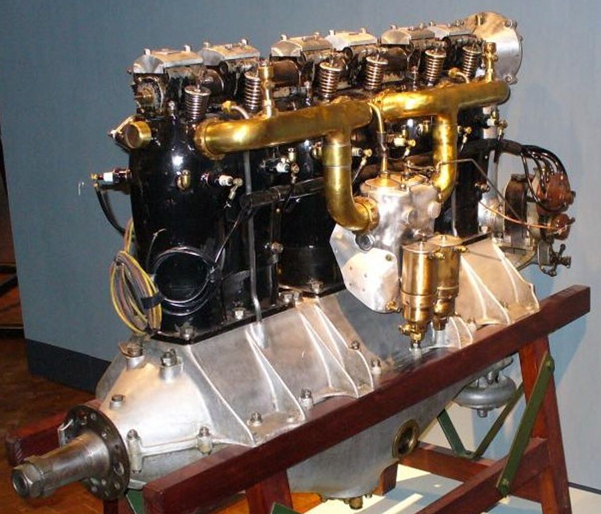
| (Franco Atirador) | (Aconcagua) |
The 1914 Type F12556 (D.II), an inline six often called the 120-hp model, had a 125 mm (4.921") bore, 150 mm (5.906") stroke and 10.179 l (621.16 in³) displacement. It delivered 123 hp at 1,400 rpm.
The Type 1466, (D.III) also called the 160-hp model, was heavily used by the German Army during WWI starting in 1914 with nearly 12,000 produced. This water-cooled inline six had a 140 mm (5.512") bore, 160 mm (6.299") stroke, 14.778 l (901.81 in³) displacement and 4.5:1 compression ratio. It produced 162.5 hp at 1,400 rpm and weighed 294 kg (618 lb). Fuel and oil consumptions were 0.522 and 0.035 lb/hp/hr. Its individual cylinders were machined from steel forgings and the valve ports screwed and welded to the cylinder head; the whole assembly was encased in welded-on sheet-steel water jackets. Inclined valves with 68 mm (2.677") clear diameter and 11.25 mm (0.443") lift, were operated by an overhead camshaft and rocker arms. The rocker arms worked through slots in the malleable-iron camshaft casing, which was provided with felt packing strips and baffle plates for oil retention. The inlet valves opened 2° late and closed 35° late; the exhaust valves opened 63° early and closed 13° late. A compression release scheme was provided for starting. The six-throw crankshaft was supported in seven plain bearings, with the bearing caps integral with both upper and lower crankcase halves. The crankcase was made from aluminum alloy and featured long bearing bolts, which held the halves together and also secured the cylinders. The H-section shank connecting rods had caps secured by two bolts. The piston was formed by screwing and welding a cast-iron skirt to a forged-steel head that was integral with the piston pin bosses. Two Mercedes carburetors supplied the mixture, and the oil was delivered under pressure by a plunger pump. Bosch Type ZU-6 magnetos provided dual ignition.
The D.IIIa, or 180-hp model, introduced in 1917, was an improved F1466 with a number of the F1686 design features. The crankshaft. and connecting rods were practically identical with those used in the D.III. The D.IIIa had domed pistons, a 4.64:1 compression ratio, improved valve gear, and developed 174 hp at 1,400 rpm. Early D.I, D.II and D.III models had square rocker boxes with rocker arm ends exiting through vertical slots cut into opposing rocker box sides. The D.IIIa and later D.III engine versions had the rocker boxes relocated aft on a tubular camshaft housing, with sealed rocker arm shafts protruding forward through the rocker box fronts. The vertical camshaft driveshaft was a new design, and a water pump similar to the F1686 design was placed below the engine at the anti-propeller end.
Also introduced in 1917 was the D.IIIaü, an unofficial designation where the ü indicated 'uber', which meant it had a still higher compression ratio to give better altitude performance. This meant that full throttle running at sea level was prohibited. It featured an altitude-compensated heated carburetor. The D.IIIaü was capable of 180 – 200 hp. Final D.III versions, the D.IIIav and D.IIIavü, which produced 200 – 217 hp, were introduced in 1918 and featured slightly taller aluminum alloy pistons with increased compression.
 |
 |
LXC.jpg) |
LXC.jpg) |
|
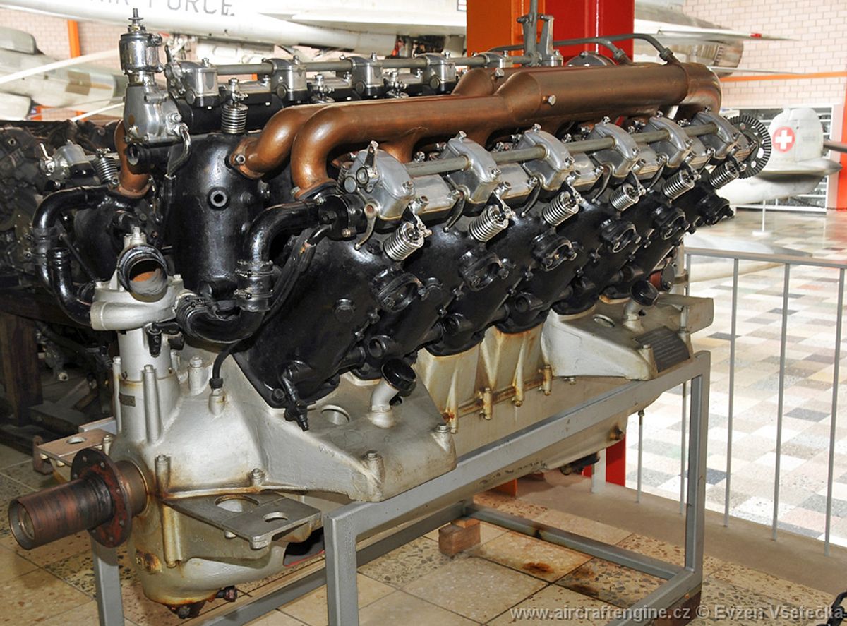
| (Evzen Vsetecka) | (Valder137) | D.III (AEE) | D.IIIa (AEE) | |
 |
 |
 |
| Type F1686 (AEE) | ||
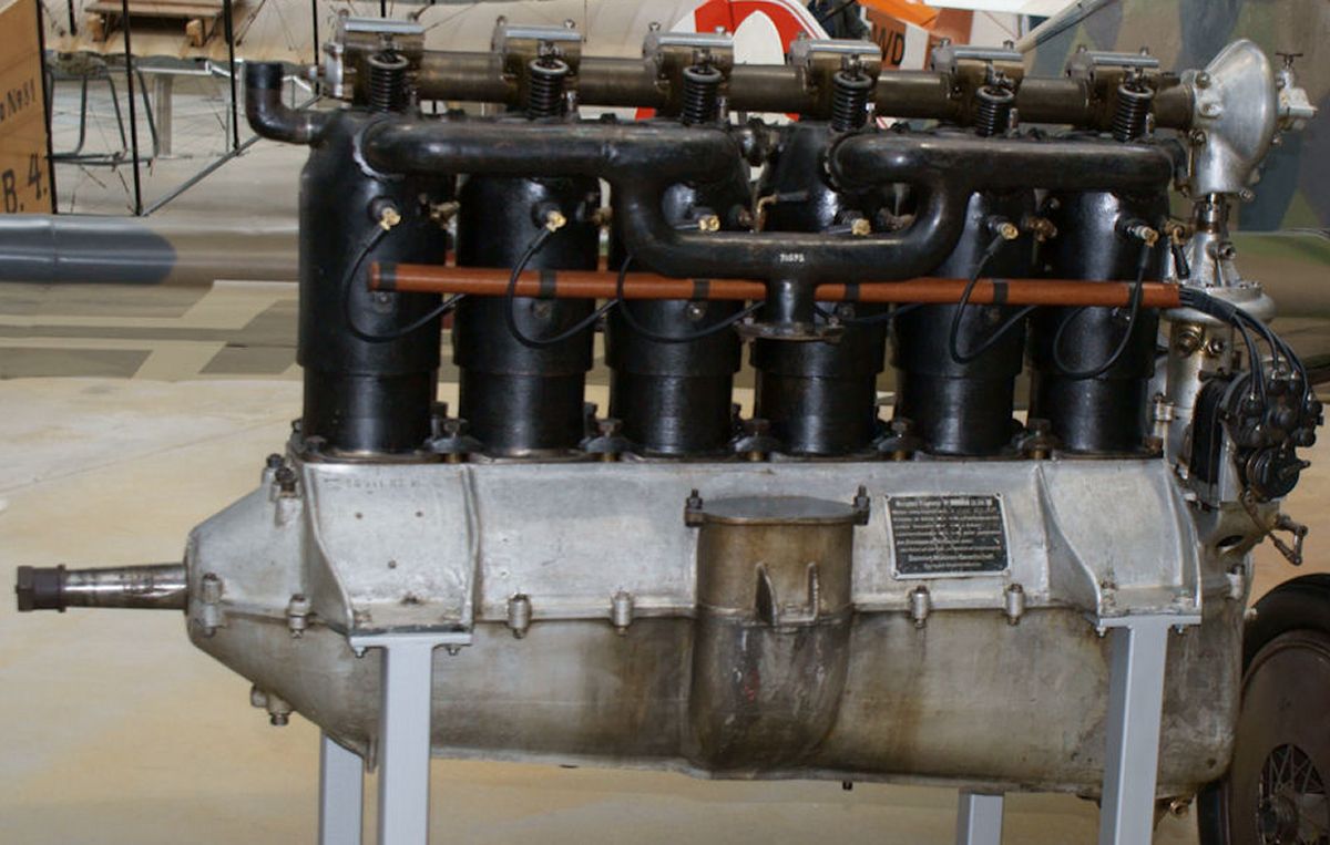
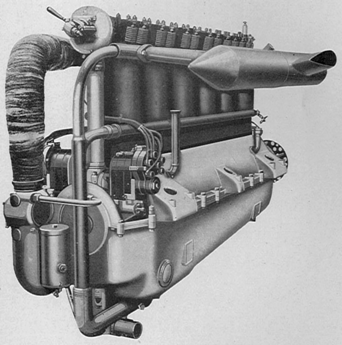
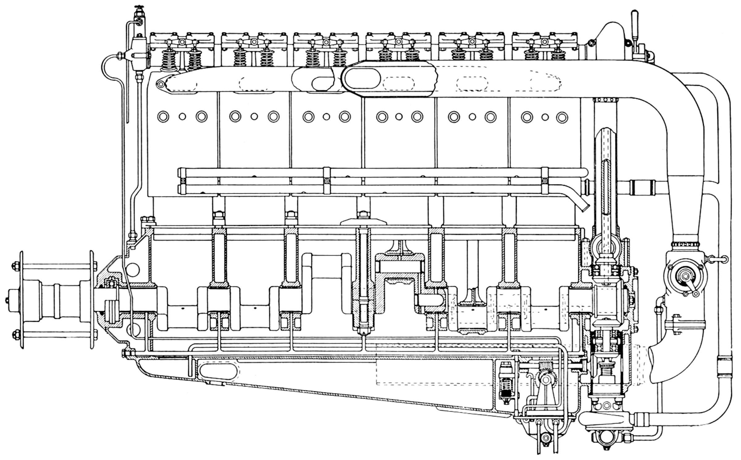
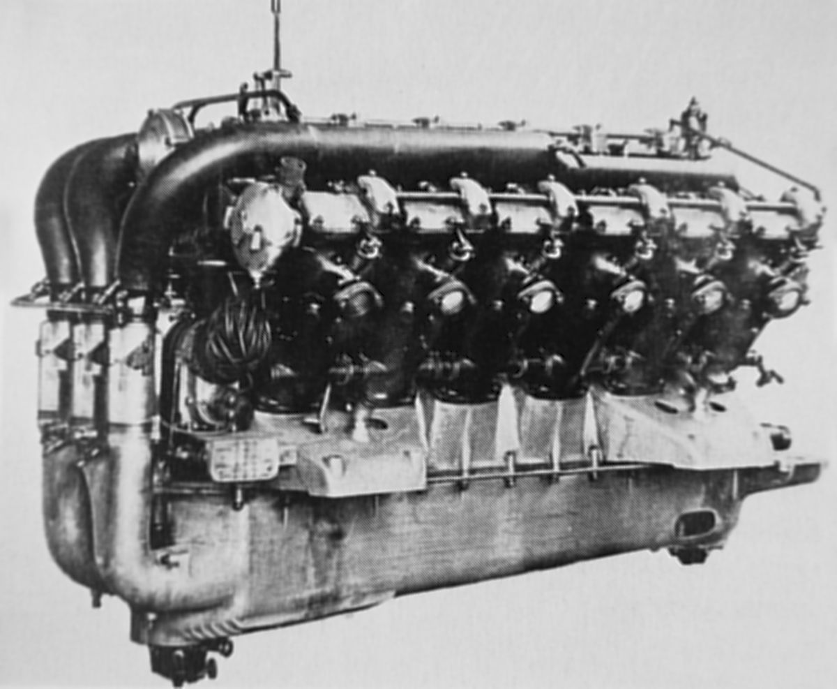
The Type F1686, or 260-hp model, was an inline six with a 160 mm (6.299") bore, 180 mm (7.087") stroke, 27.715 l (1,325.13 in³) displacement and 4.94:1 compression ratio that delivered 252 hp at 1,400 rpm and weighed 936 kg (936 lb). It was 1,969 mm (77.5") long and 1,168 mm (46") high. Steel cylinder barrels were screwed and welded into forged-steel dome-shaped cylinder heads onto which steel double valve ports were welded. A four-section sheet-steel water jacket was welded in place. The valves were inclined to the vertical axis and operated by T-shaped rocker arms and an overhead camshaft supported by seven phosphor-bronze bearings in a malleable-iron housing. Siamesed valve ports led to four interchangeable valves with 55.2 mm (2.173") clear diameters. Inlet valve lift was 10.125 mm (0.399") and the exhaust valve lift was 10 mm (0.394"). Inlet valves opened 1° late and closed 49°; exhaust valves opened 51° early and closed 18° early. A compression relief cam opened 12° ABC and closed 44° BTC. The six-throw crankshaft was supported in seven plain bearings, and the connecting rods had H-section shanks and four-bolt caps. The piston had a forged-steel head, a cast-iron skirt and was fitted with three compression rings above the pin and one oil-scraper ring below the pin. A twin-jet Mercedes carburetor, situated at the rear, fed into a large six-cylinder manifold. Fuel consumption was 0.541 lb/hp/hr. An eccentric-driven plunger pump provided pressure lubrication. Two Bosch ZH-6 magnetos supplied dual ignition.
 |
| Type 1468 (D.IV) (Museo scienza tecnologia Milano)"> |
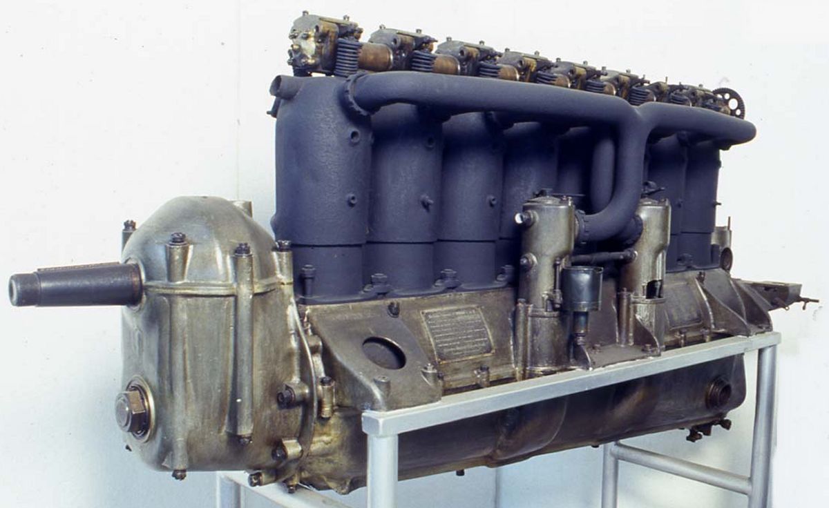
The Type F1468 (D.IV), an inline eight employing Type F1466 cylinders, was used by the German Army for a time. The compression ratio was increased to 4.73:1 and a 29:21 spur gear propeller reduction was used. With a 140 mm (5.512") bore and 160 mm (6.299") stroke, the displacement was 19.704 l (1,202.41 in³), and the engine produced 242 hp at 1,350 rpm. Weight, including exhaust manifolds, was 408 kg (900 lb). The cylinders, pistons, and connecting rods were identical to those used in the Type F1466. The inlet valve lift was 11.4 mm (0.449") and the exhaust valve lift was 10.48 mm (0.414"). The inlet valves opened 2° late and closed 51° late; exhaust valves opened 52° early and closed 16.5° late. The eight-throw one-piece crankshaft was supported in nine plain bearings. The crank web thicknesses progressively increased toward the propeller end. Fuel consumption ranged from 0.524 to 0.582 lb/hp/hr; oil consumption was 0.042 - .047 lb/hp/hr. Two Mercedes twin-jet carburetors furnished the mixture, and two Bosch HL8 magnetos the dual ignition. Forced lubrication was delivered by a multiple-plunger pump.
Two experimental inline sixes patterned after the F1686 had 235 mm (9.252") bores, 250 mm (9.843") stroke and displaced 65.060 l (3,970.23 in³). It produced 650 hp at 1,250 rpm and weighed 1,050 kg (2,315 lb ). Each cylinder had four 90 mm (3.543") valves. Work on these engines did not continue beyond the test bench.
 |
 |
 |
|
| Type F14618 D.VI (Evzen Vsetecka) | Type F14618 (AEE) | ||
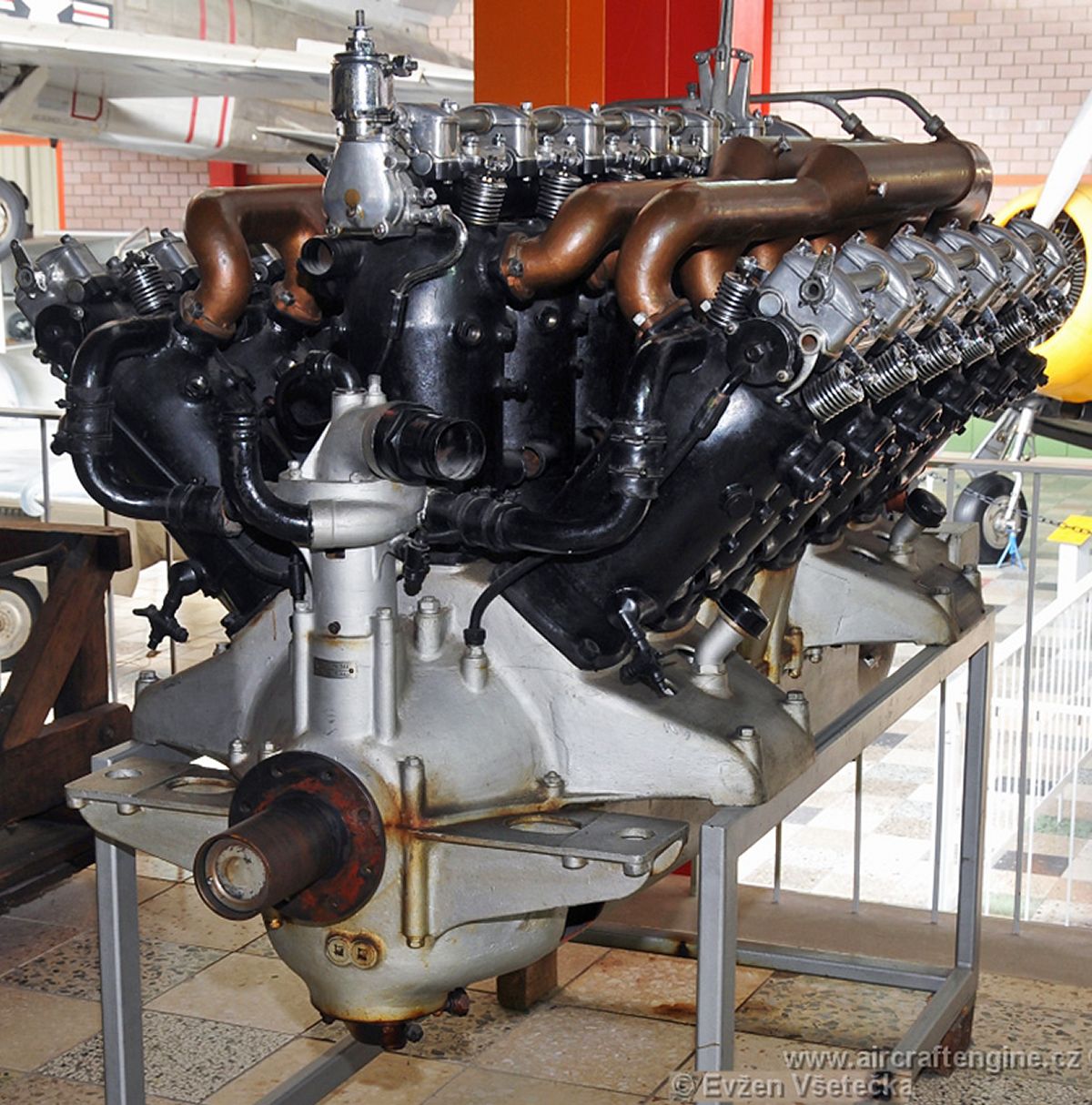
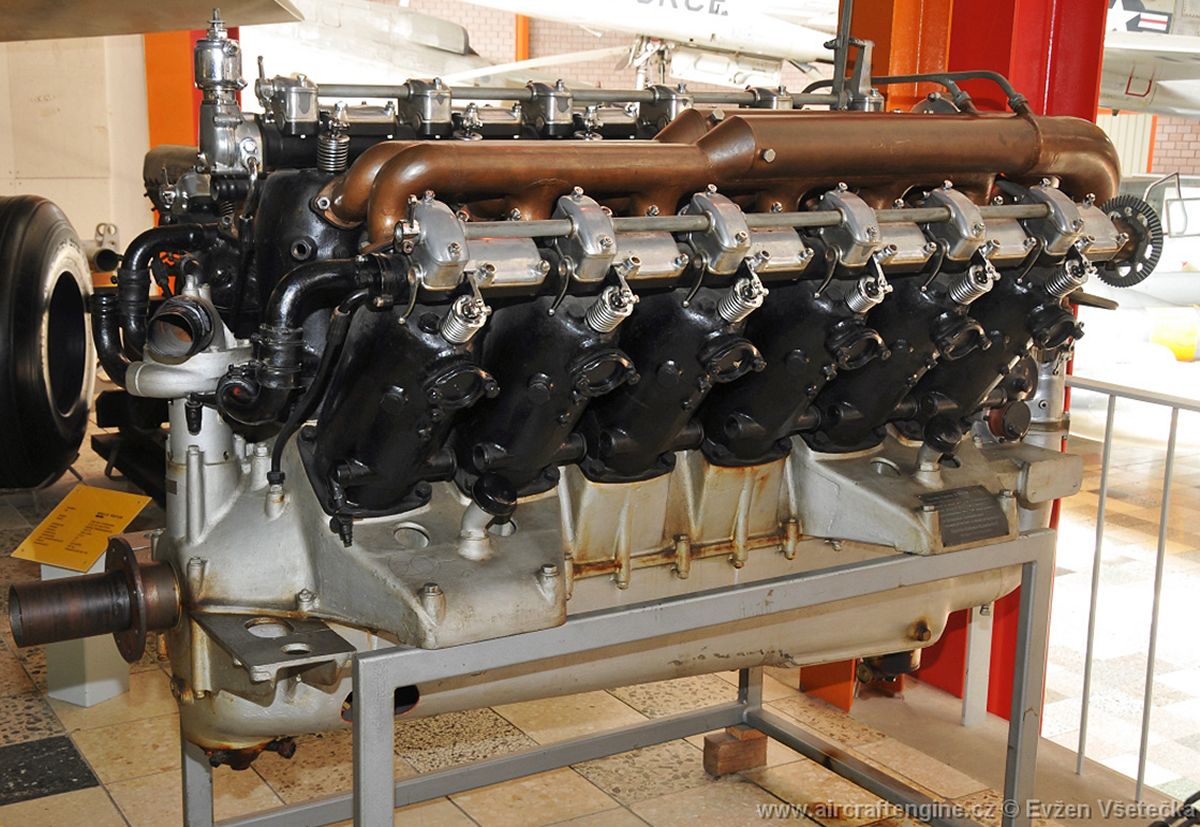
The Type F14618 (D.VI), was a 40° W-18 that used F1466 cylinders. Tests were nearly complete when WWI ended. With a 44.334 l (2,705.4 in³) displacement, it developed 500 hp at 1,450 rpm. In addition to the cylinders, valves, camshafts, oil pumps, etc., were common to the F1466.
 |
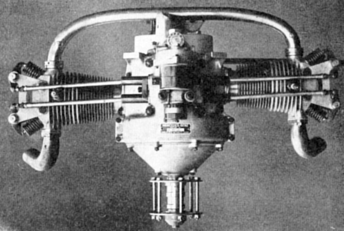 |
| Type F7502 (A39) |
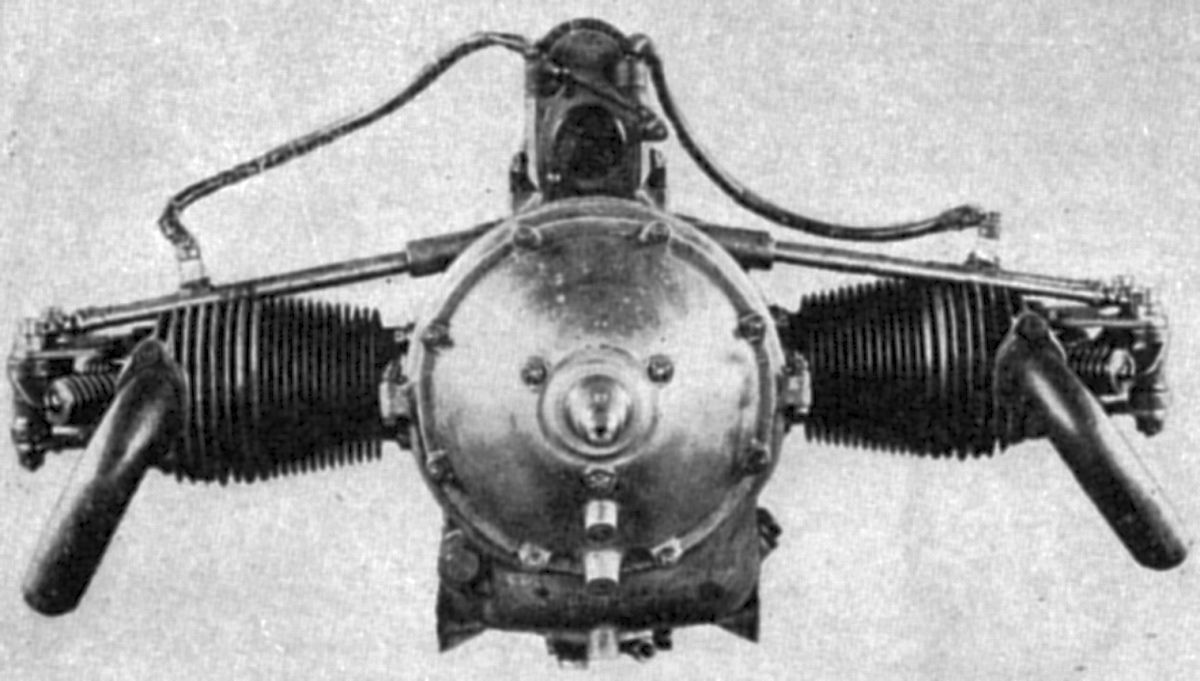
When WWI ended, all German military aircraft engine production ceased. However, the Type F7502 was an air-cooled horizontally-opposed two-cylinder developed for light airplanes starting in 1919. With a 75 mm (2.953") bore, 100 mm (3.937") stroke, 0.884 l (53.92 in³) displacement and a 3:1 planetary reduction gear, it produced 20 hp at 3,000 rpm, and weighed 48 kg (106 lb). Fuel and oil consumptions were 0.66 and 0.010 lb/hp/hr. It was 590 mm (23.22") long, 775 mm (30.51") wide and height 470 mm (18.5") high. Steel cylinder barrels with integral cooling fins were screwed into cast-iron heads. Two front-mounted inclined exhaust valves and two inclined aft-mounted inlet valves in each cylinder were operated by rocker arms and push rods actuated by a short camshaft with one inlet and one exhaust cam. The camshaft was at the crankcase top and driven by spur gears from the crankshaft. A single magneto, also mounted on the crankcase top, was driven through spur gears from the camshaft end. A horizontal shaft, located below and parallel with the crankshaft, drove a gear-type pressure oil pump through bevel gears, as well as a plunger-type scavenging pump. The crankshaft was supported upon ball bearings and it was made in three sections. The front section included the front web and a large-diameter flywheel that enclosed the planetary reduction gears. The center section included the central web and the two crank-pins. The rear section carried the rear web and tail shaft. The end section webs were split and clamped to the central section crankpins. The H-section connecting rods had bronze-bushed solid-ring big ends, and the piston pins were locked in the smaller ends. The trunk-type aluminum alloy pistons had four rings. The aluminum alloy crankcase was a box-type casting with bolted-on front and rear covers. A Mercedes-Benz triple venturi carburetor received its air through a crankcase heating duct.
In 1926, Daimler-Motoren Gesellschaft, Benz & Cie, and Manheim merged to form a new firm that became known as Daimler-Benz-Aktiengesellschaft. Several German training airplanes, along with ones in The Netherlands, Norway, Denmark, Sweden, and Russia, required the 120-hp model. Arrangements were made to resume production through a 1926 contract with Marabini-Aviation of Paris, France. The latter firm undertook to manage the sale of these engines.
The first Model DIIa constructed under this contract successfully completed a 100-hr test in December 1926. This engine followed earlier design and manufacturing practice with its vertical cylinders arranged in pairs. Its bore was 125 mm (4.921"), stroke was 150 mm (5.906"), and displacement was 11.045 l (673.99 in³). It was rated 130 hp at 1,450 rpm. Fuel and oil consumptions were 0.506 and 0.033 lb/hp/hr. Dry weight was 204 kb (449 lb), length was 1,450 mm (57"), width was 1,727 mm (68"), and height was 1,150 m (45.27). The cylinders were machined from steel forgings, and each pair was encased by a welded-on sheet-steel water jacket. The valves were inclined in the cylinder head and operated through rocker arms by a camshaft carried in a tubular housing bolted to the cylinder heads. The camshaft was driven by an enclosed vertical shaft and bevel gears located at the engine rear. The bevel gear at the crankshaft rear also drove a vertical shaft extending below, which drove the water pump directly and an oil pump located in the crankcase base by skew gears and a horizontal shaft. The trunk-type pistons were aluminum alloy. The aluminum alloy crankcase was cast in two section and joined along the horizontal crankshaft centerline. The four crankshaft bearings were carried in the crankcase upper half by bearing caps. Auxiliary drive housings were cast integrally in the upper and lower crankcases. The mixture was supplied from a water-jacketed Mercedes-Benz duplex carburetor through manifolds feeding three cylinders each. Two Bosch magnetos furnished dual ignition. The lubrication system was a combination wet and dry sump with a pump submerged in the sump delivering pressurized oil to the bearings and another pump maintaining a constant oil level. A Bosch self starter was also provided.
The Daimler-Benz company continued building aircraft engines through WWII. However, these later engines are beyond this article's scope.
References
Angle, Glenn D, ed. Aerosphere 1939 (New York, New York: Aircraft Publications, 1940).
Anble, Glenn D, ed. Airplane Engine Encyclopedia (Dayton, Ohio: Otterbein Press, 1921).
Image Sources: A39 = Aerosphere 1939; AEE = Airplane Engine Encyclopedia; Flt = Flight Magazine; NARA = U.S. National Archives and Records Administration; UKNA = United Kingdom National Archives.
Send mail to
![]() with questions or comments about this web site.
with questions or comments about this web site.
![]()