Selected Early Engines
Manly, Maximotor, Maybach, Mercedes, Michel, Michigan Aero, Miller, Minerva, Morehouse, Murray-Willat
Compiled by Kimble D. McCutcheon
Published 17 Oct 2022; Revised 6 Nov 2022
Manly
|
|
|
|
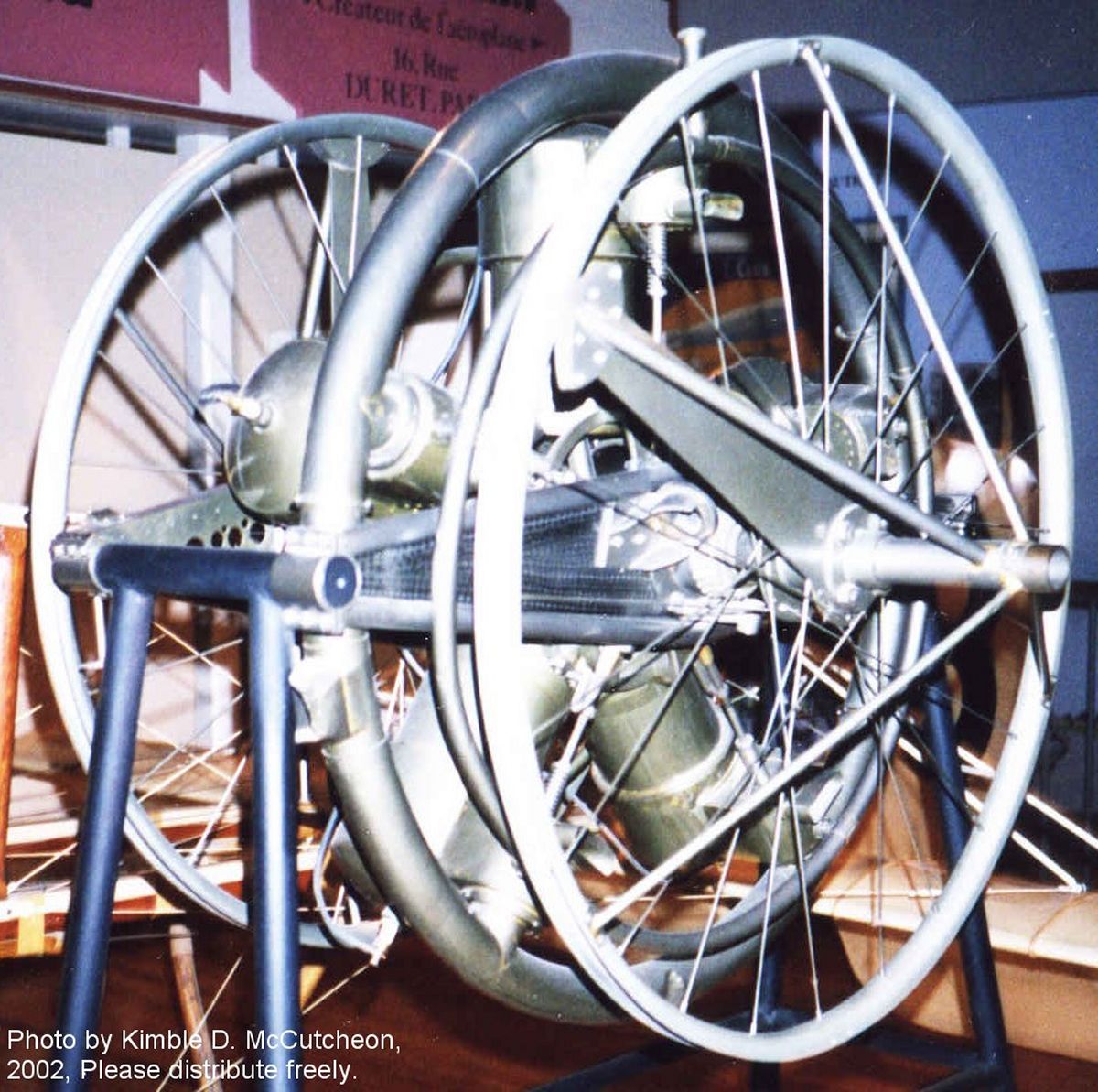
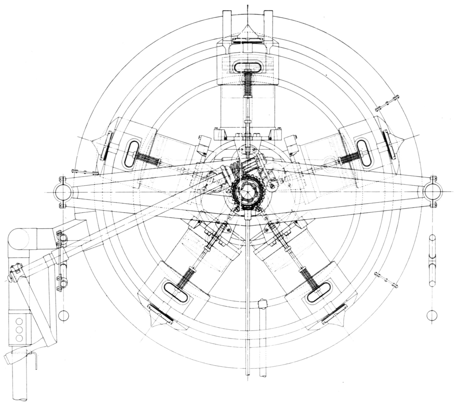
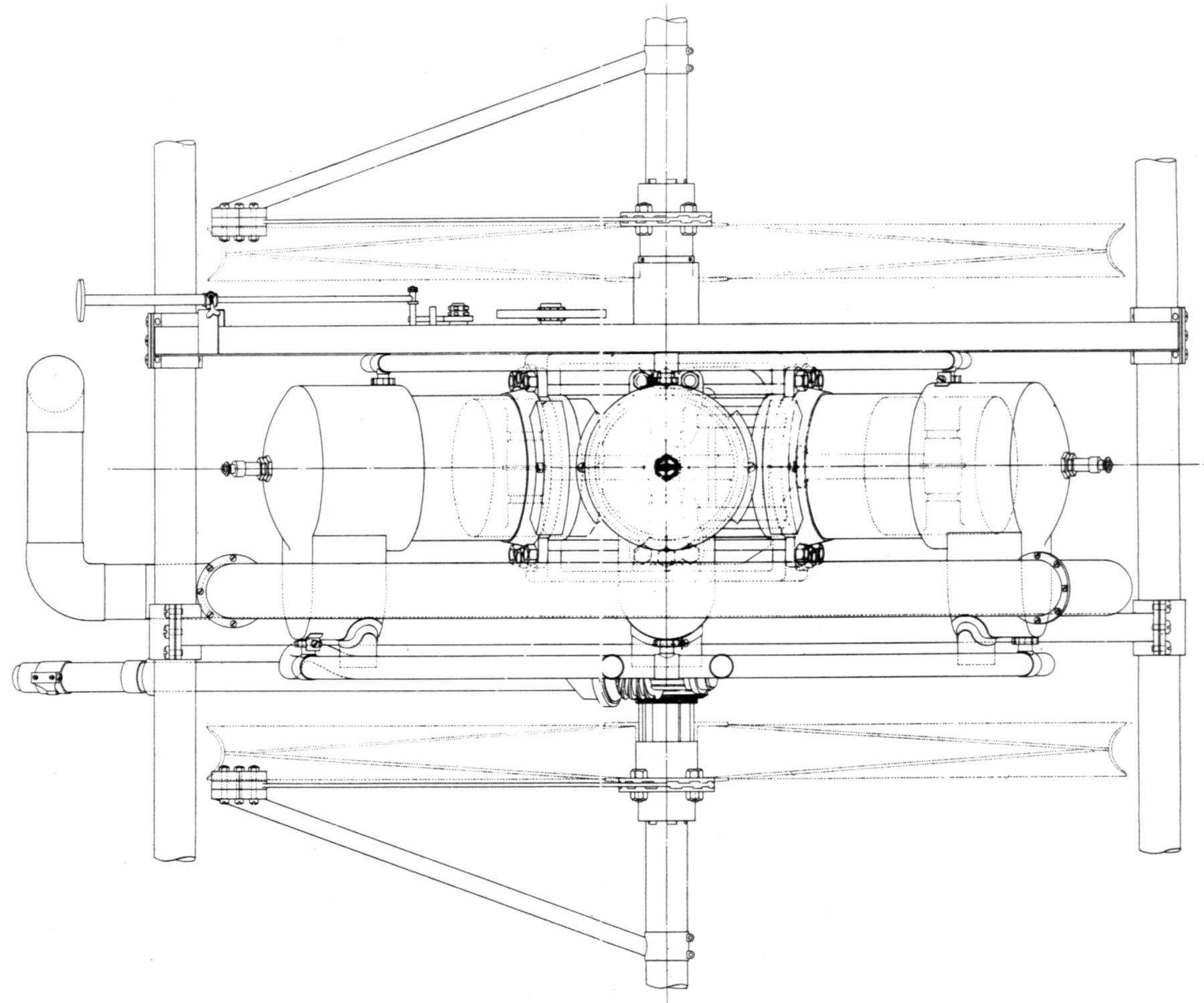
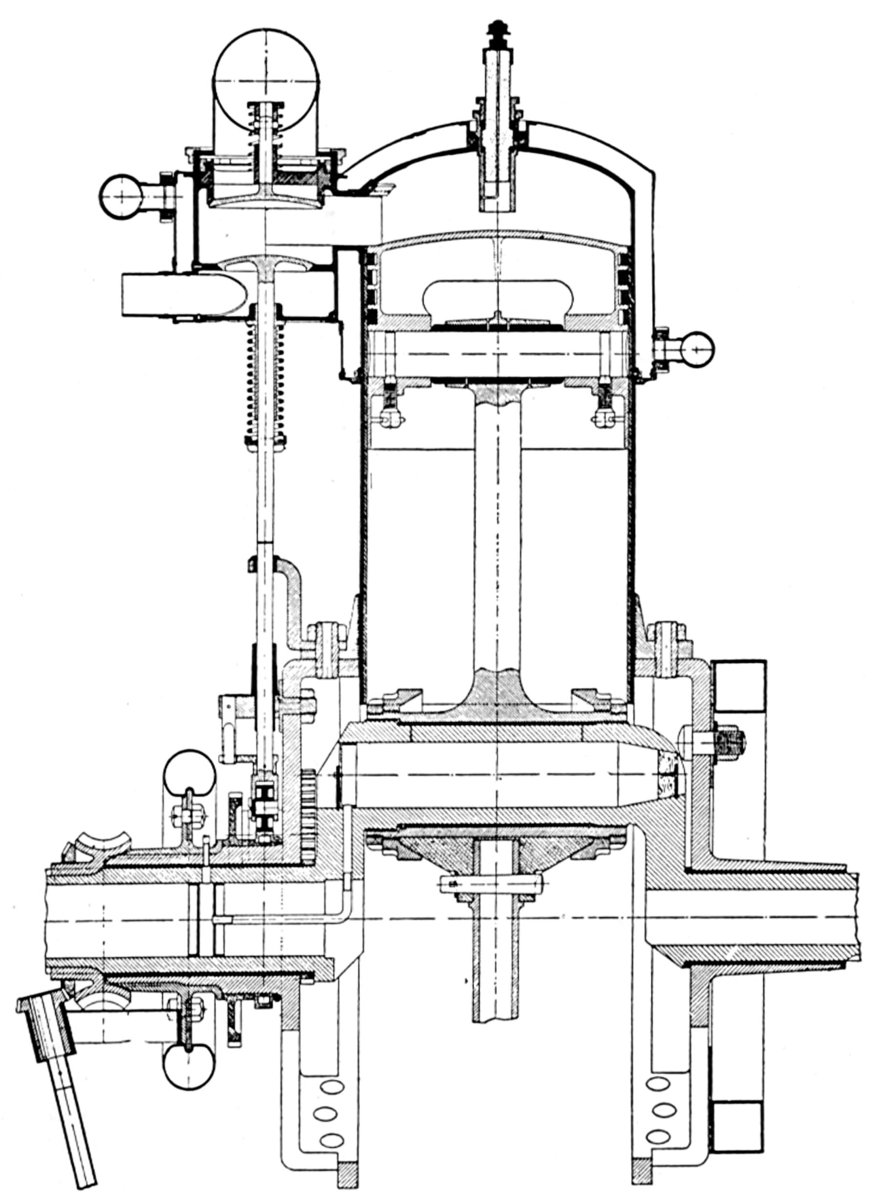
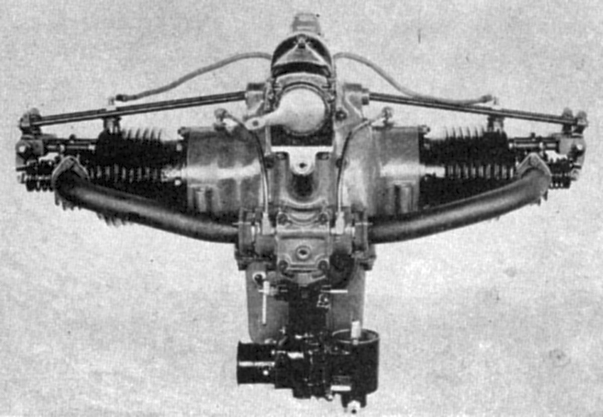
| The Manly-Balzer 1903 Aircraft Engine (AEE, NARA) | |||
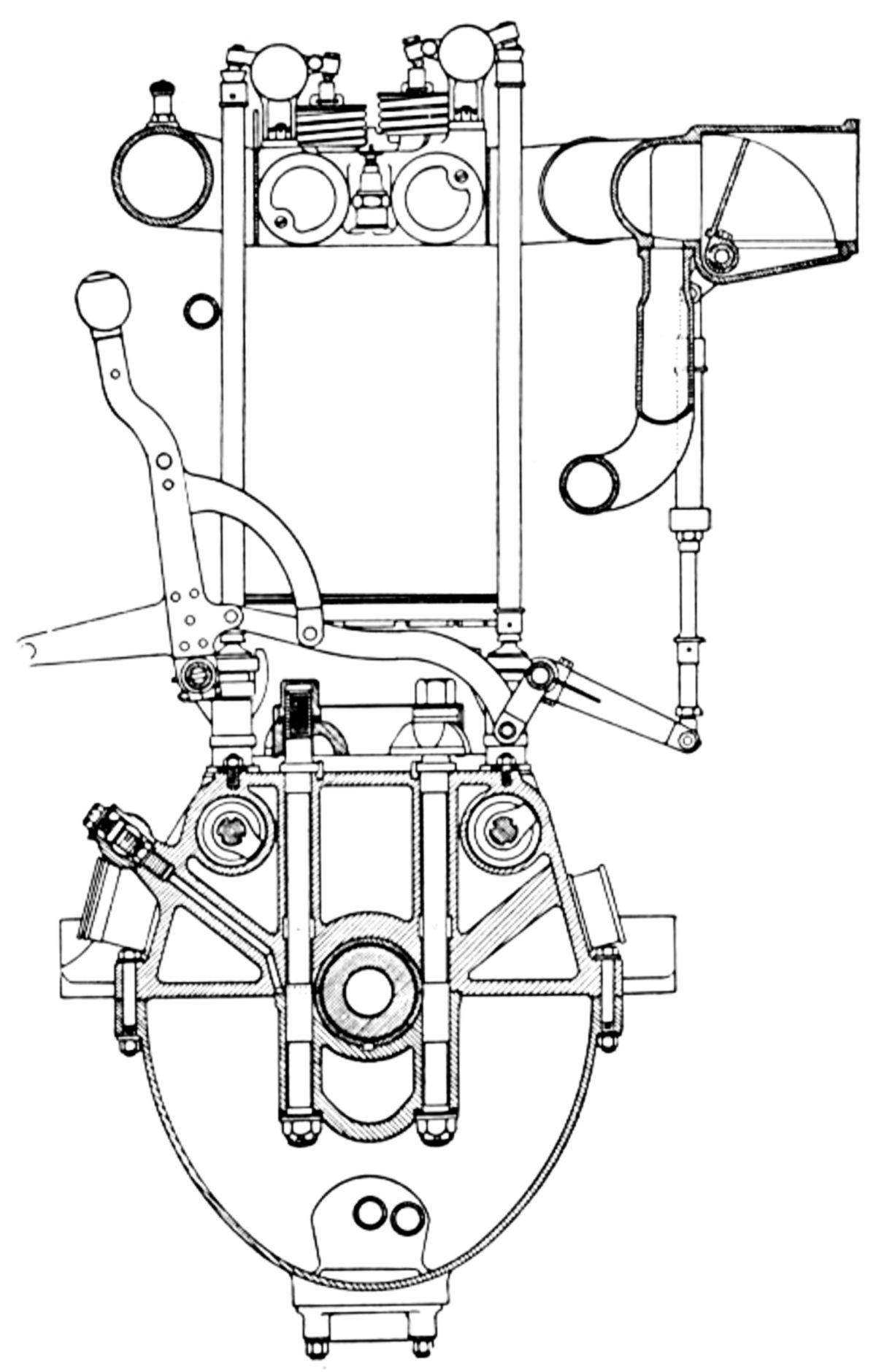
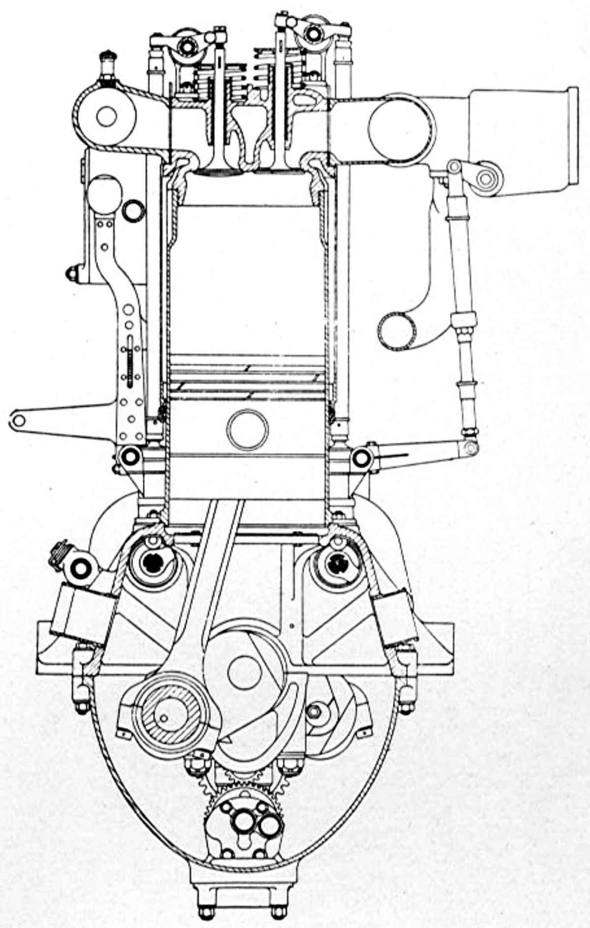
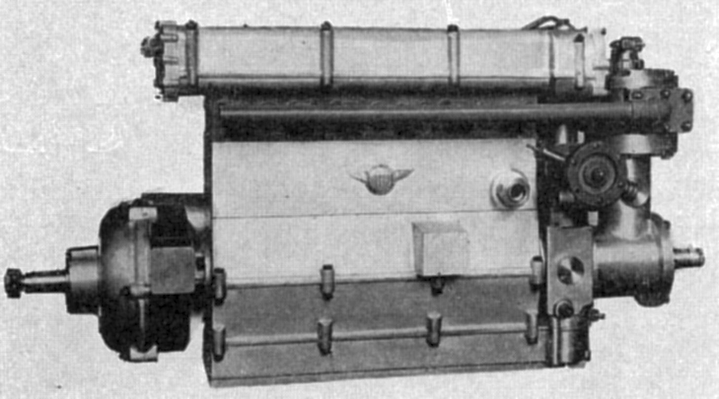
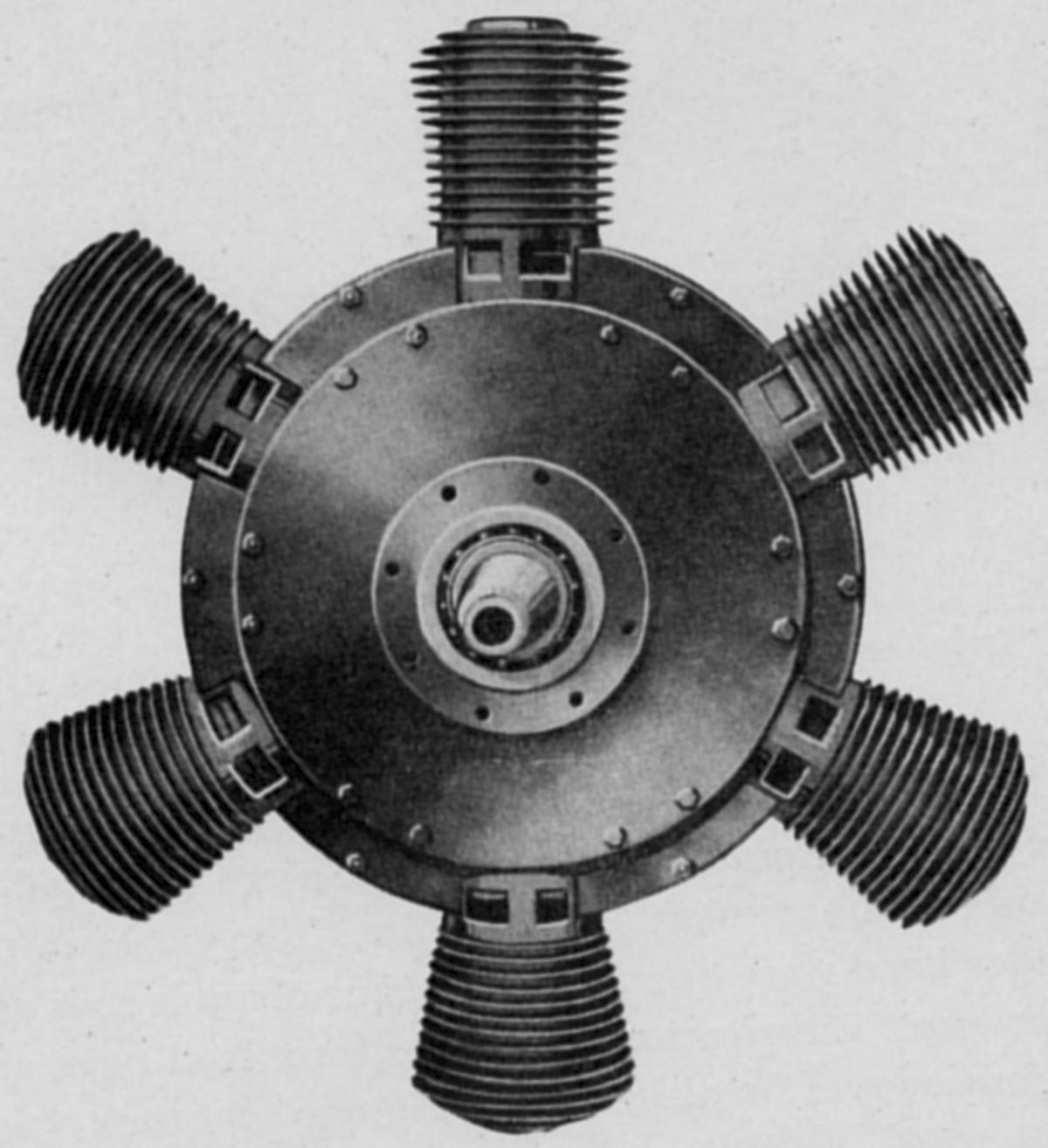
The first successful airplane engine began as an air-cooled 5-cylinder rotary designed by Stephen Marius Balzer (1864 – 1940), an American mechanic, inventor and founder of the Balzer Motor Company. When Smithsonian Institution Secretary Samuel Pierpont Langley learned of this engine he ordered one for his experimental airplane, the Aerodrome. Balzer had difficulty converting the engine for aircraft use, so Charles Matthews Manly (1876–1927), an American engineer and Langley's technical assistant began to rework the engine. The 1903 result, a water-cooled 5-cylinder radial with a 5.0" (127.0 mm) bore, 5.5" (139.7 mm) stroke and 539.96 in³ (8.848 l) displacement, developed 52.4 hp at 950 rpm and weighed 207.5 lb (94 kg), or 3.96 lb/hp.
Cylinders were drawn from steel plates, and the walls machined to 0.0625" thickness. Cast-iron liners were then pressed into place. The valve-chamber forgings and sheet-steel water jackets were brazed in place. The F-head cylinders had the automatically-operated inlet valves overhead while the exhaust valves were operated by a single two-lobe cam rotating opposite the crankshaft direction and at 0.25 speed. The slipper type connecting rods used taper nuts to secure the assemblyr. The master rod had a solid shank section, while the slipper rods were made with tubular shank sections. A spark coil and vibrator provided ignition that was distributed to the correct cylinder. The spark plugs were a custom design, and oil cups provided lubrication.
Maximotor
 |
 |
 |
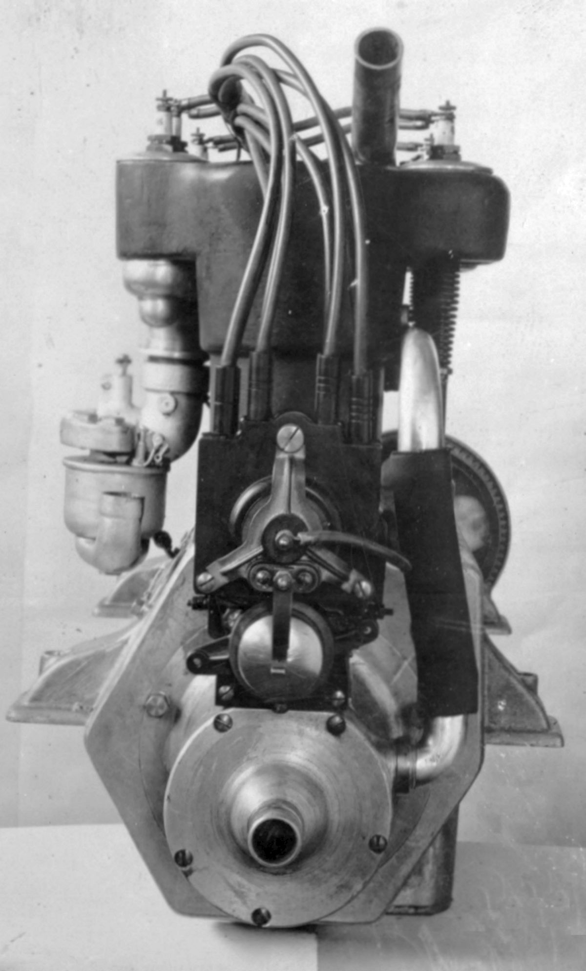
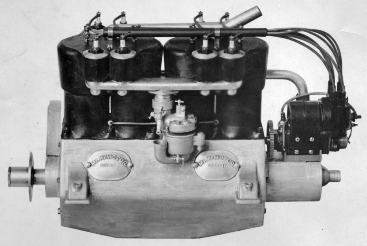
| Maximotor Model A-4 (NARA) | ||
Maximotor engines were built from 1911 until 1913 by Max Dingfelder, who founded the Dingfelder Motor Company of Detroit, Michigan in 1903.
The Model A-4 was a water-cooled inline four with a 4.5" (114.3 mm) bore, 5.0" (127 mm) stroke and 318.09 in³ (5.213 l) displacement. It was rated 50 hp at 1,200 rpm and weighed 210 lb (95 kg).
The Model A-6 used six Model A-4 cylinders for a 477.13 in³ (7.819 l) displacement. It was rated 75 hp at 1,200 rpm, produced 85 hp at 1,600 rpm and weighed 340 lb (154 kg).
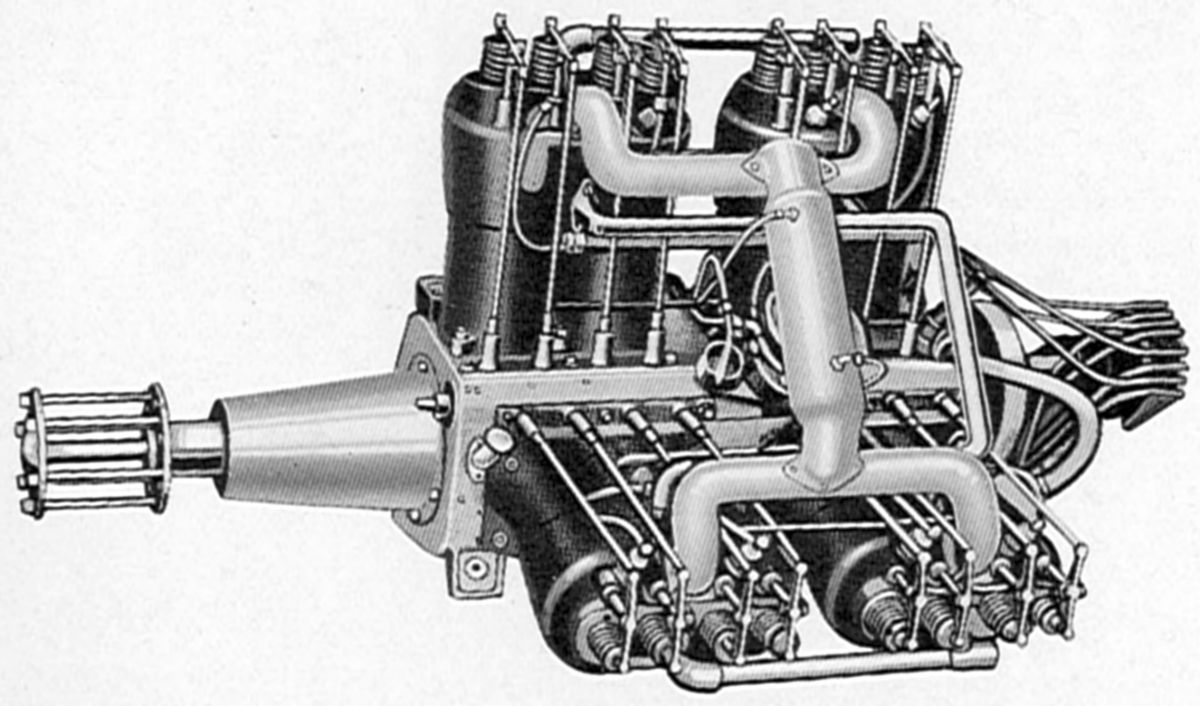 |
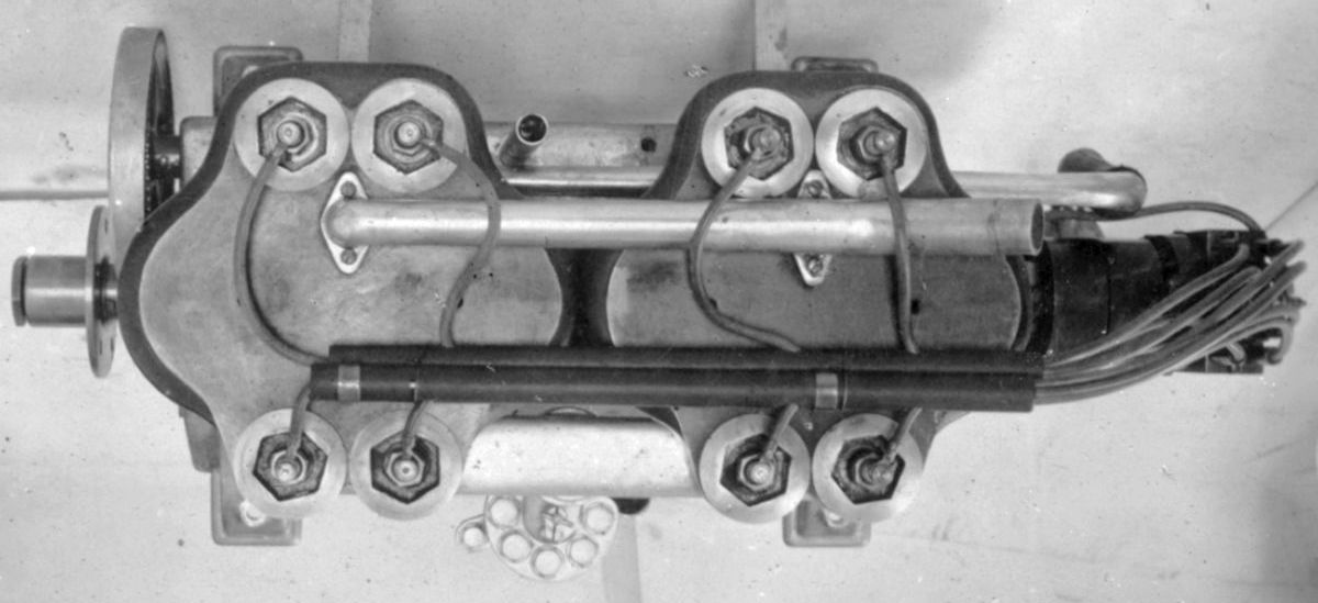
| Maximotor Model A-8 (AEE) |
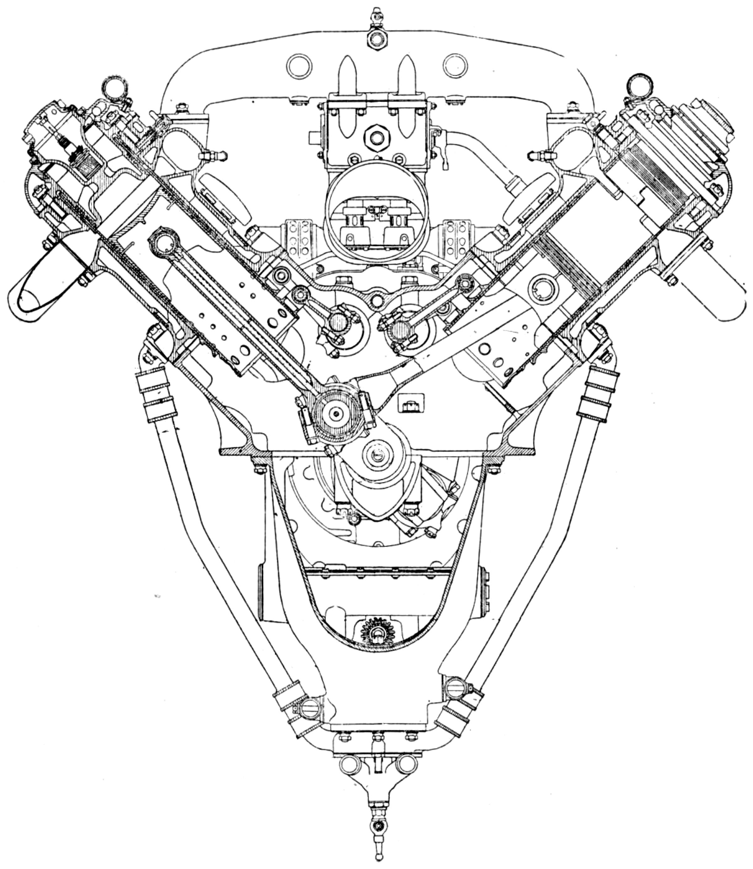
The Model A-8 was a 90° V-8 using Model A-4 cylinders that displaced 636.17 in³ (10.425 l). It was rated 110 hp at 1,350 rpm, 115 hp at 1,600 rpm and weighed 420 lb (190.5 kg).
The Model B-6 was a water-cooled inline six with a 5.0" (127 mm) bore, 6.0" stroke and 706.858 in³ (11.583 l) displacement. It was rated 115 hp at 1,600 rpm and weighed 385 lb (175 kg).
Maximotor also built a water-cooled inline four with a 5.25" (133.35 mm) bore, 5.50" (139.70 mm) stroke and 476.246 in³ (7.804 l) displacement. It was rated 70 hp and weighed 215 lb (98.5 kg). It was equipped with semi-steel cylinders, Kingston carburetors, Mea magnetos, and employed a force-feed lubrication system. It was 41" (1,041 mm) long, 16: (406 mm) wide and 29" (737 mm) long.
Maybach
Wilhelm Maybach, technical director of the Daimler-Motoren-Gesellschaft (DMG), left that company in 1907 to found Luftfahrzeug-Motorenbau GmbH (Aircraft Engine Building Company) on 23 Mar 1909 with his son, Karl Maybach, director. In 1912, the company name became Maybach-Motorenbau GmbH (Maybach Engine Construction Company), a firm that developed and manufactured gasoline and diesel engines for Zeppelins. Its Maybach Mb.IVa was used in aircraft and airships during WWI.
Early Maybach engines were water-cooled vertical inline sixes. The 200 hp model was used exclusively in the Parseval, Schiitte-Lanz and Zeppelin airships. During WWI the 300-hp gasoline engine was developed for airplane use.
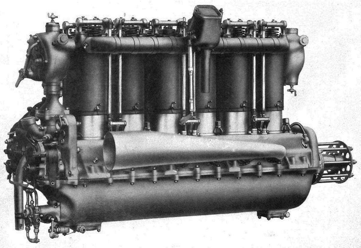
The 1909 Maybach AZ, its first aircraft engine, had a 160 mm (6.299") bore, 170 mm (6.693") stroke and 20.508 l (1,251.48 in³) displacement. It was rated 140 hp at 1,200 rpm. Fuel and oil consumptions were 0.51 and 0.025 lb/hp/hr. Weight was 449 kg (990 lb). It used T-head cast iron cylinders.
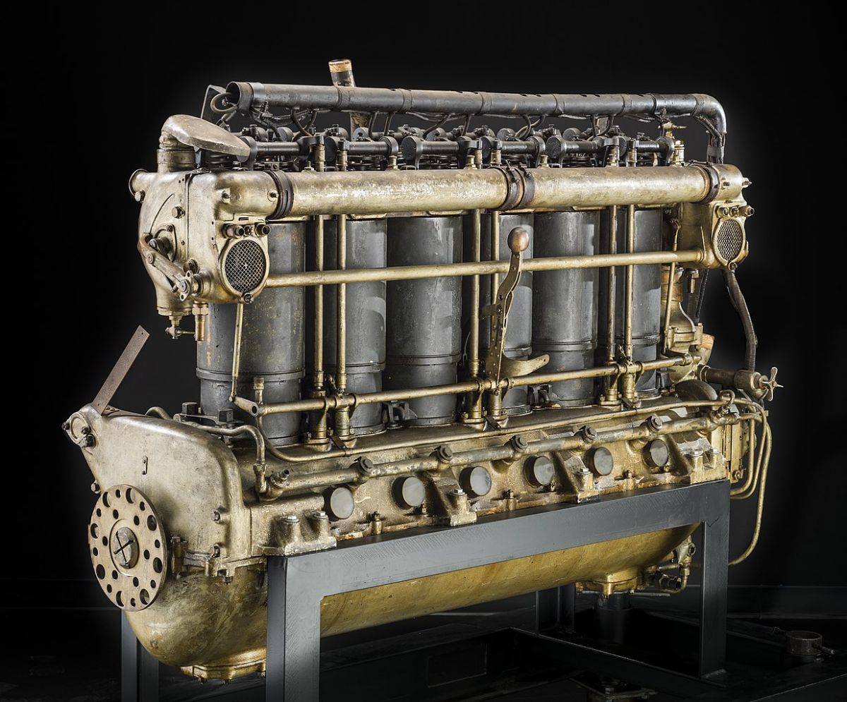
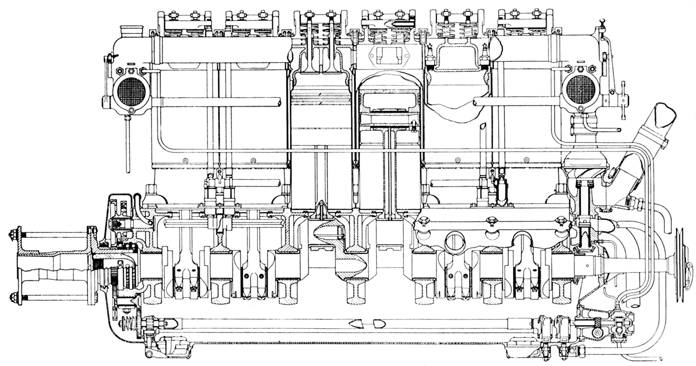
The Maybach CX airship engine had a 150 mm (5.906") bore, 190 mm (7.480") stroke, 20.145 l (1,229.32 in³) displacement and 5.94:1 compression ratio. It was rated 200 hp at 1,200 rpm. Its cylinders consisted of steel barrels screwed into malleable-iron heads with integral water jackets that were packed at the lower end. Each individual cylinder was fitted with five vertical valves in the cylinder head – two 48 mm (1.890") diameter inlets with 9.3 mm (0.366") lift, and three 35 mm (1.378") diameter exhausts with 7.88 mm (0.301") lift. A push rod on each cylinder side operated the inlet and exhaust valves via a single rocker arm. A large circular water joint between each cylinder was made tight by a rubber ring encircled by a sheet brass band clip. The six-throw crankshaft was supported in seven plain bearings with separate caps, and the connecting rods had bored out square-shank sections. The cast iron pistons employed three top compression rings. The piston pins were locked in the piston, and the bearing was lubricated by oil carried from the crankpin through a pipe within the connecting rod's hollow shank. Seven gauze-covered ventilators on one crankcase side and corresponding openings on the opposite side communicated with a marine-type cowl to affect crankcase breathing and scavenging. The two water-jacketed carburetors were attached to the end cylinders at the water jacket flanges. These carburetors consisted of a barrel throttle, a main air regulator, a jet, a damping device and a constant-head gravity fuel-feed reservoir. The carburetors and fuel-feeding device were of unique design, that was unaffected by altitude variation. The pressure lubrication system employed piston oil pumps. The engine was equipped with a mechanical starter, and two Bosch ZH6 magnetos provided dual ignition.
The 1914 MB.III (Maybach designation IR) had a 140 mm (5.512") bore, 175 mm (6.890") stroke, 16.163 l (986.33 in ³) and 4.37:1 compression ratio. It produced 160 hp at 1,400 rpm and weighed 282 kg (622 lb).
The 1915 MB.IV (Maybach designations HS, HS D, HS Lu(a high-compression altitude version)) had a 165 mm (6.496") bore, 180 mm (7.087") stroke and 23.093 l (1,409.22 in³) displacement. It delivered 250 hp.
 |
 |
 |
 |
 |
 |
| (Wiki) | (NARA, AEE) | ||||
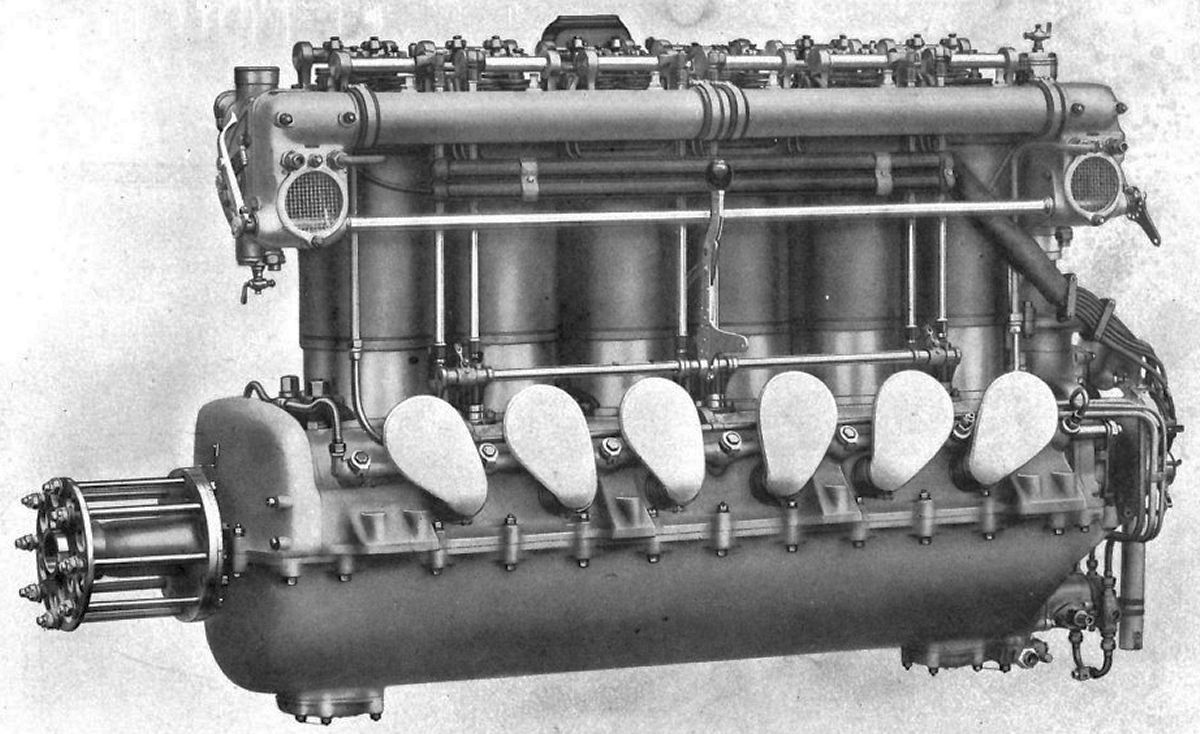
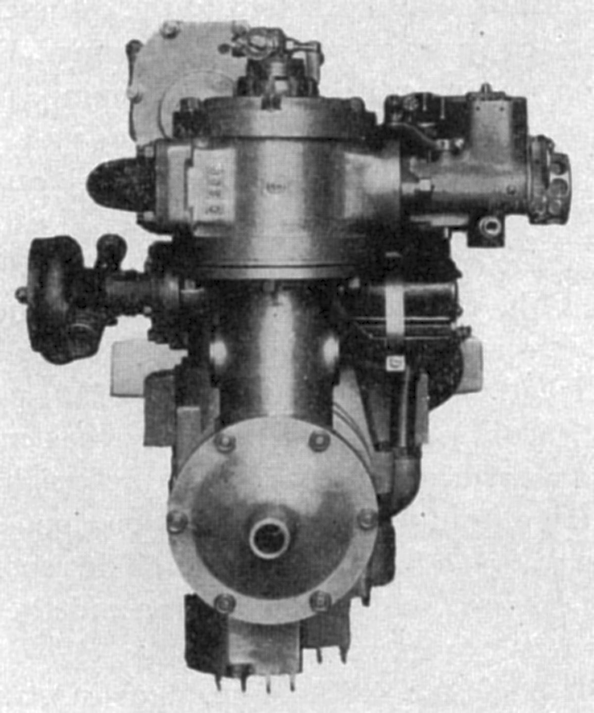
The 1916 Mb.IVa airplane engine, generally referred to as the 300-hp Maybach, had a 165 mm (6.496") bore, 180 mm (7.087") stroke, 23.093 l (1,409.22 in³) displacement and 6.08:1 compression ratio. Although the Mb.IVa was rated 302 hp at 1,700 rpm, it was intended to achieve reasonable power at altitude. Full throttle operation was prohibited at sea level, therefore it actually developed 245 hp at 1,400 rpm from sea level up to 1,800 m (5,905 ft). Fuel and oil consumptions were 0.464 and 0.0223 lb/hp/hr. Dry weight was 418 kg (921 lb), and the water content was 10 kg (22 lb). The design was similar to the CX. The cast iron cylinder heads received screwed-in steel cylinder barrels, but the forged steel water jackets were machined separately, both inside and out to a very thin wall thickness and fastened to the head by threads and to the cylinder barrel lower end by a packing nut. There were four vertical valves in each cylinder with a port diameters of 48 mm (1.890"), 30° seats and 9.53mm (0.375") lift. The valve ports were siamesed. The inlet valve opened 8° early and closed 35° late; the exhaust valve opened 33° early and closed 7° late. Two water connections between adjacent cylinder heads replaced the large diameter flanges on the CX model. The crankshaft, connecting rods, and pistons were similar to those used in the CX. Two Maybach carburetors with 62 mm (2.44") throats were mounted at the cylinder ends and fed into a manifold that had a baffle plate at its center. Crankcase ventilation was again provided. The Maybach oil plunger pumps were replaced by three gear pumps. Pressurized oil fed the main bearings through diagonally drilled holes in the upper crankcase fed by external connections. The fuel pump was an opposed plunger type driven by an eccentric. Two Bosch ZH6 magnetos furnished dual ignition.
Maybach built an extremely large experimental water-cooled inline six with a 200 mm (7.874") bore, 240 mm (9.449") stroke, 45.239 l (2,760.65 in³) displacement and 6.07:1 compression ratio. The cylinders each had four 62 mm (2.441") diameter valves. Despite using a 110-lb flywheel, the vibration was too severe for the crankcase.
The Treaty of Versailles greatly curtailed Maybach-Motorenlsau after WWI. It became a Zeppelin Works subsidiary at Friedrichshafen. By 1925, development of a water-cooled six-cylinder four-stroke Diesel was begun. This engine design resembled some of the larger airship engines, but the cast iron cylinders and crankcase made it very heavy. Output was 150 hp at 1,300 rpm. The crankshaft main journals ran on roller bearings and crankshaft front end featured a damper to reduce vibration at critical speeds. The intake and exhaust valves were carried in cages in the cylinder head and they were operated from a single overhead camshaft through rocker arms. The camshaft also operated the fuel injector valves located at the side of each cylinder head. These valves could be removed for inspection. Since the spray nozzles were adjustable, the needles worked on a constant stroke. A control shaft for the variable spray nozzles was located on the engine side over the fuel valves, which permitted low fuel consumption and widely-variable engine speed. A three-stage compressor, mounted on roller bearings, was attached at the engine rear. Compressed air for starting passed through a distributor that timed its admission into the cylinders. An automatic starting valve in each cylinder closed immediately when combustion occurred. This engine was not particularly well adapted for airship use, and further development was deferred pending the outcome of tests with gaseous fuels.
 |
 |
| Maybach VL-1 (Maybach) | |
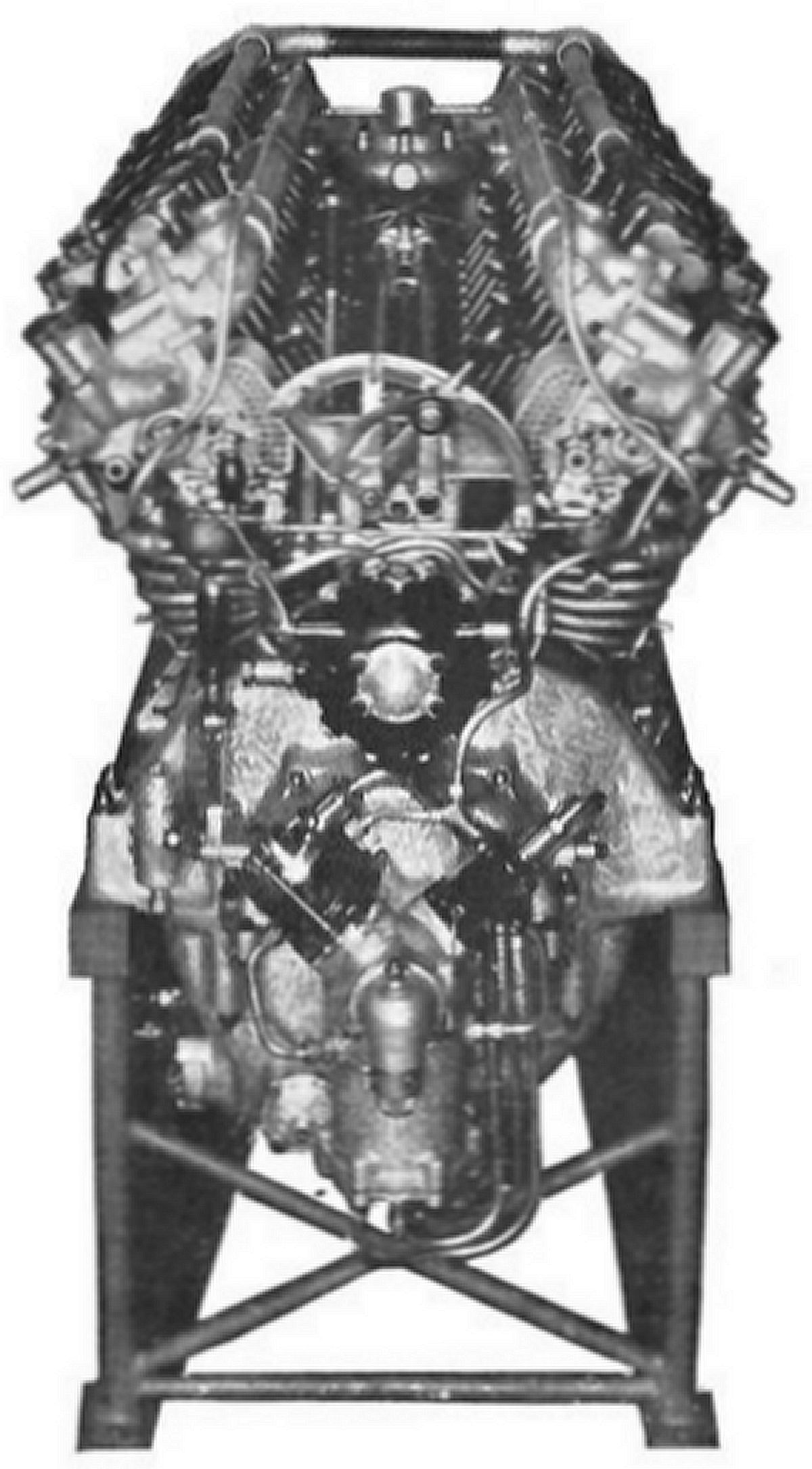
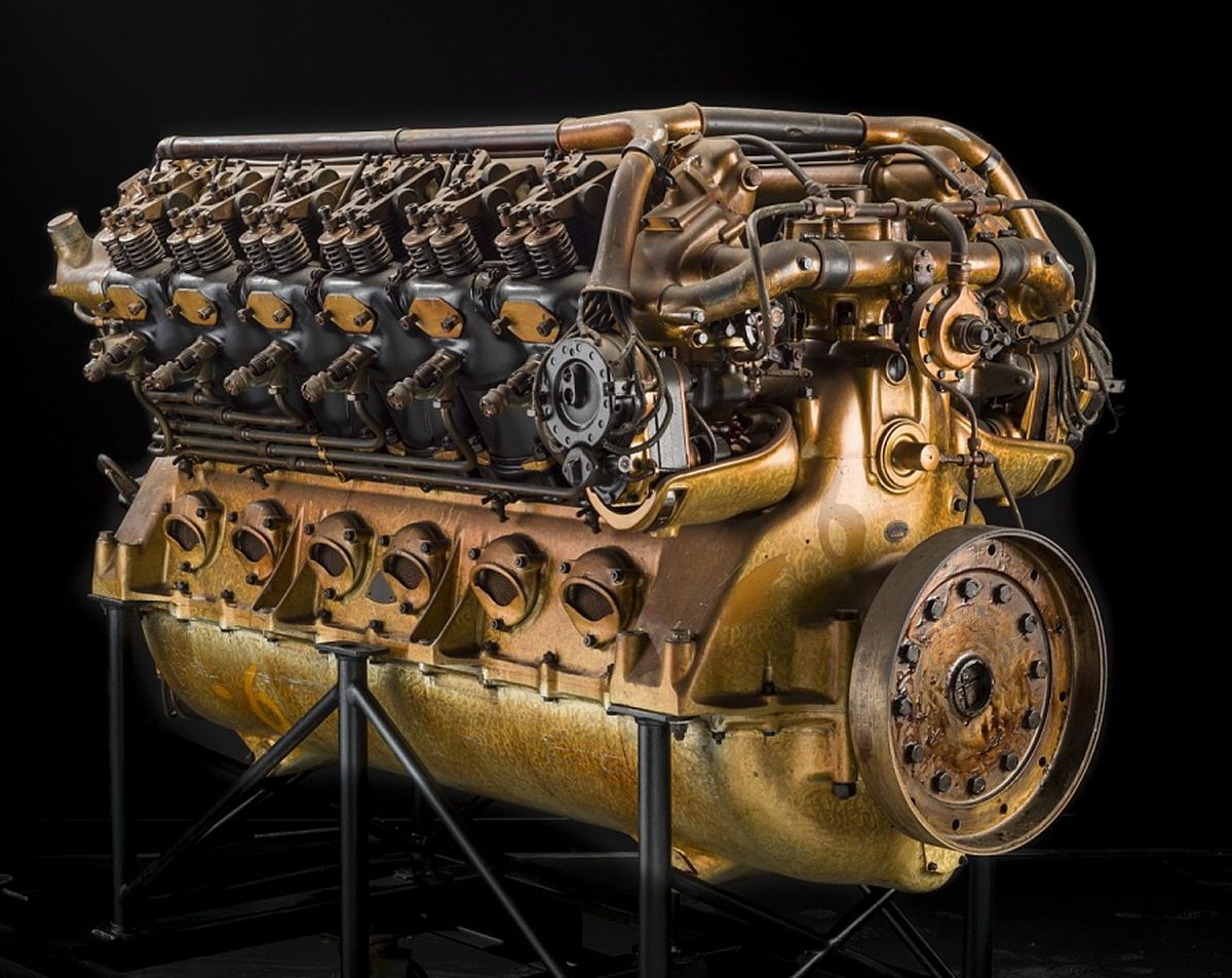
Maybach-Zeppelin VL-1 engines built during 1924 were successful in the U.S. Navy ZR-3 Los Angeles airship. This 60° V-12 had a 140 mm (5.512") bore, 180 mm (7.087") stroke, 33.251 l (2,029.10 in³) displacement and 5.8:1 compression ratio. It featured roller crankshaft main and rod bearings, a vibration damper, one inlet and two exhaust valves per cylinder operated by a single camshaft between the banks in conjunction with push rods and rocker arms, two Maybach carburetors per bank, compressed air starting, and pressure lubrication. The camshaft could be shifted fore and aft to achieve engine operation in either direction.
 |
 |
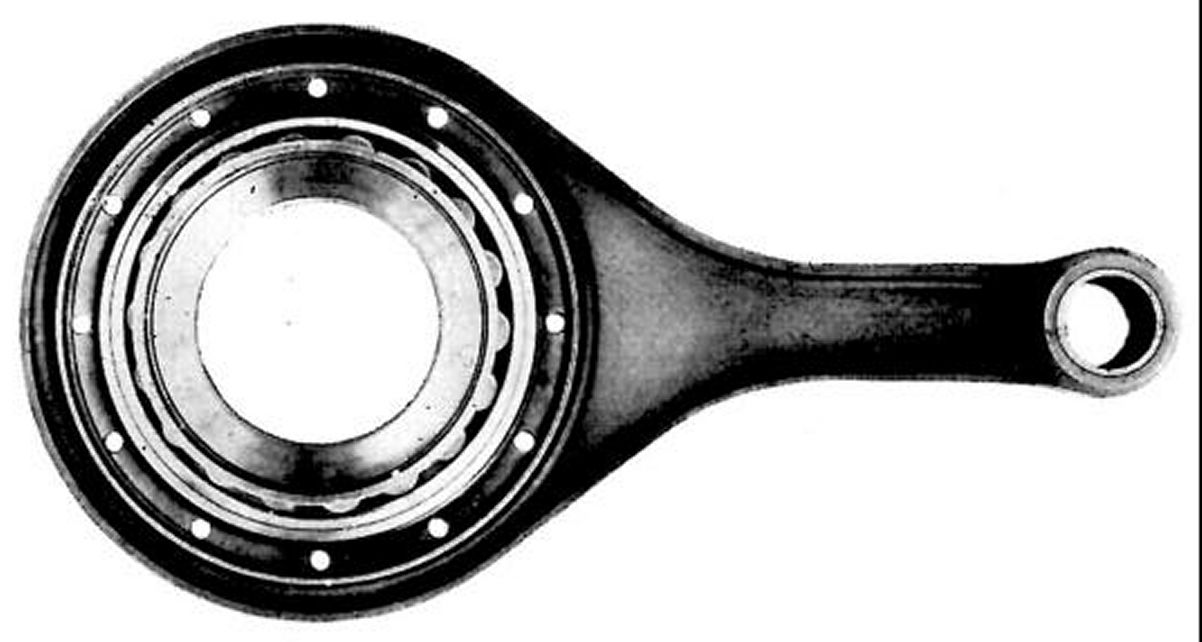 |
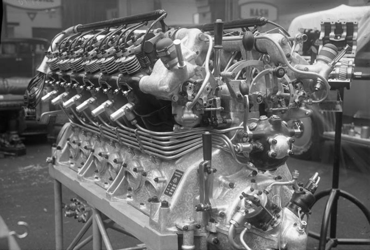
| Vl-2 (Wiki) | VL-2 (Wiki) | VL-2 Connecting Rod (Maybach) |
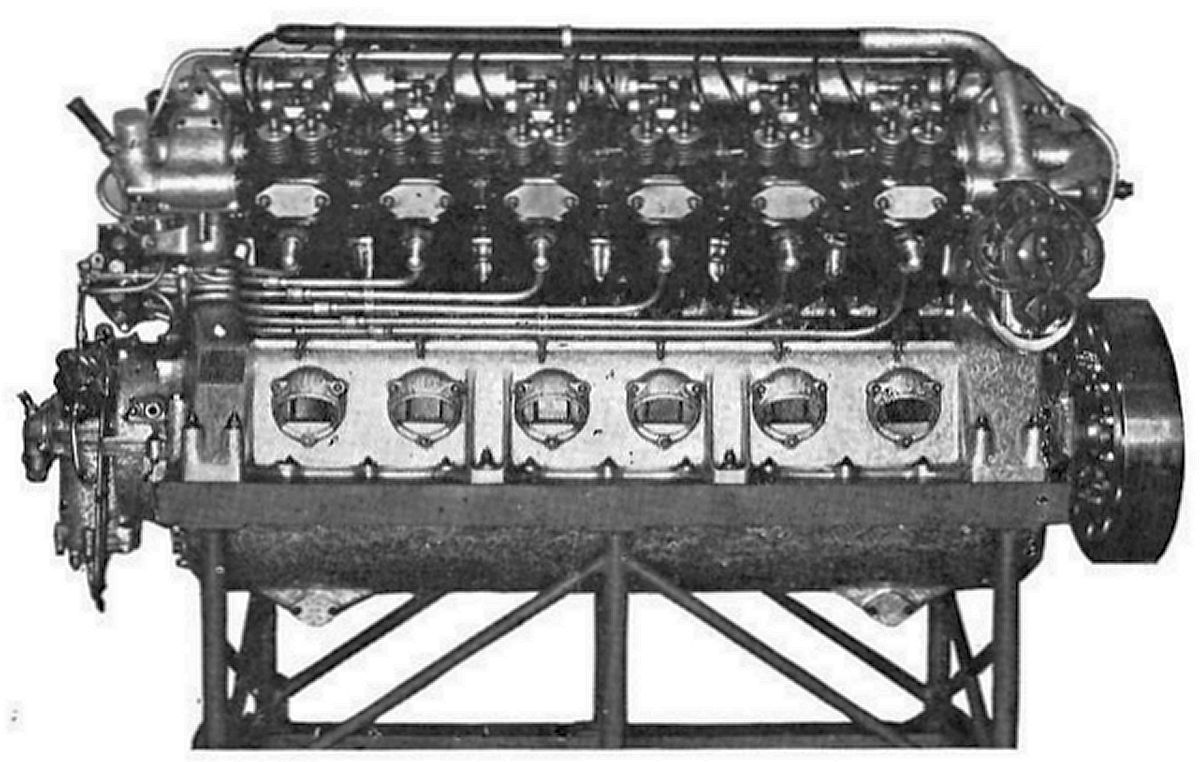
The VL-2 engines were developed to operate continuously in the Graf Zeppelin for long periods at the minimum possible fuel consumption. These engines were also used in the U.S. Navy ZRS-5 Macon airship. This water cooled 60° V-12 had a 140 mm (5.512") bore, 180 mm (7.087") stroke, 33.251 l (2,029.10 in³) displacement and 7.0:1 compression ratio. Its maximum continuous rated power at sea level was 550 hp at 1,600 rpm and its cruise rating was 450 hp at 1,450 – 1,500 rpm. Full throttle fuel and oil consumption was 0.44 - 0.46 and 0.011 lb/hp/hr. The engine dry weight was 1,148 kg (2,530 lb). It was 1,956 mm (77") long, 914 mm (36") wide and 965 mm (38") high. Mayback claimed the VL-2's long life and reliability under steady operation was due to the use of roller bearings. The H-section shank connecting ran side-by-side on the crankpins. Each rod had a solid-ring big end fitted with a roller bearing. The counterbalanced crankshaft ran on seven roller bearings. A vibration damper also was provided to reduce vibration at all speeds. The pistons were aluminum alloy. The individual cylinder skirts extended for some distance into the crankcase and had high flanges to absorb the lateral forces. The cylinder liner was cast integral with the head, and a sheet-metal jacket welded to the head had a sliding fit at its lower end. Each cylinder was fitted with one inlet and two exhaust valves situated vertically in the head and operated from a single camshaft by push rods and rocker arms.
In airship installation, the exhaust manifold was cooled by air inside the car, and the exhaust was mixed with air and discharged outside the car. Cooling water passed in and out of the cylinders through double gland connections arranged near the upper ends. The water pump was located at the engine flywheel end above the crankcase. The crankcase was a rugged aluminum casting, the upper half supporting the main bearings. The lower section was an oil pan that exposed all of the inner mechanism when removed. The oil pumps were arranged in the lower half so that they might be removed at the side without further disassembly. Two suction pumps picked up oil from each end of the lower crankcase and delivered it through a filter to a tank at the engine side. The pressure pump delivered oil through the caps to the main bearings, and it reached the connecting rod bearings by squirt nozzles and deflectors. Two Bosch type GF magnetos operated by resilient clutches from the crankshaft flywheel end furnished dual ignition. Normally, the engine was provided with four carburetors, one for each three cylinders, secured at each cylinder row end and heated by the cooling water. By hollowing the throttle valves, gaseous fuel, known as Blau gas, was adopted satisfactorily for use with the fire-proof Maybach carburetors. Pipes led the gas from gas bags into the throttle shafts, and the flow of gas was controlled by an adjustable valve according to the throttle position. A valve in the gas feed line permitted a change from gaseous to liquid fuel in a few seconds without any interruption in the engine operation or loss of power.
Compressed starting air was supplied sequentially to the cylinders in one cylinder row through a distributor. The distributor was operated by a manually-advanced cam that controlled the distributor valves; when ignition occurred, the air supply was cut off by a pressure-controlled valve. A compressed air supply was maintained by a two-stage compressor located at the crankshaft end. The centrally located camshaft in the upper crankcase could be shifted fore and aft to reverse engine direction, which proved more satisfactory and of greater simplicity than the reversing gears formerly employed.
The GO 4 was the smaller of four high-speed solid-injection railcar diesel engines that Mayback built, and which closely resemble Maybach airship engines and embrace the experience gained from the well-known Maybach 410-hp diesel railcar engine employed in railcar service over a period of several years.
The GO 4 was a water-cooled inline six with a 140 mm (5.512") bore, 175 mm (6.890") stroke, and 16.163 l (986.33 in³) displacement. It was rated 150 hp at 1,400 rpm and weighed 948 kg (2,090 lb).
 |
| Maybach GO 56h (A39) |
The GO 56h was a water-cooled 60° V-12 that made extensive use of GO 4 parts. It displaced 32.327 l (1,972.7 in³), had a 14:1 compression ratio and weighed 2,096 kg (4,620 lb). Its continuous sea-level rating was 410 hp at 1,400 rpm. The cylinders were individual grey-iron castings with head and barrel integral. Each had two inlet valves, two exhaust valves, a high-pressure injection valve and a safety valve. Each water jacket had a drain valve. The aluminum alloy pistons each had six rings. The piston pin was fixed in the upper connecting rod end and bore directly upon the piston bosses. The blade-and-fork connecting rods used floating big-end made from a special high-quality bronze. The crankcase upper and lower sections were cast from Silumin (an aluminum-silicon alloy) and supported the seven main crankshaft bearings. The lower section was primarily an oil tank with sufficient capacity to carry the entire supply. A spur gear oil pump was mounted in a detachable cover fitted to the lower section aft side. Three mounting supports were arranged on each side of the upper section. The air supply was taken from the outside through the crankcase, and through filters arranged between the two cylinder rows before entering the cylinder inlets. Inlet and exhaust valves were operated by means of rockers having hardened semi-spherical pivot sockets. The rockers had rollers contacting the cams, being supported upon fixed axles above the camshaft. The two inlet valves were controlled by a bifurcated rocker. One oil-tight aluminum cover enclosed the entire mechanism for each cylinder row. Roller crankshaft bearings were used and a radial bearing at one end carried the thrust load. A vibration damper mounted opposite the drive end reduced crankshaft torsional vibration. The oil pump and camshafts were driven from a bevel gear attached to the crankshaft. Oil was taken from the sump through a filter and led through an oil distributor shaft to the parts supplied under pressure, as well as to a governor. A second duct carried oil to the valve gear. Pressure was regulated by a spring-controlled safety valve. Solid fuel injection was accomplished by a high-pressure pump, with the fuel entering at the cylinder head center. Each cylinder had its own injection pump mounted to the aft casing side and controlled by its respective distributor shaft and injection time adjuster. The pump forced fuel through high-pressure external lines to each injection valve. Injection pumps were automatically controlled by the governor. Fuel reached the pumps under gravity head after passing through special filters. The governor, located between two injection pumps on the upper crankcase, was driven by the camshaft through an intermediate gear. The governor and pumps were connected by adjustable rods so that cylinders of both rows were governed uniformly. As a pressure oil governor, it depended upon the engine oil pressure, and in the event of a lubrication system failure, served as a safety device. Cooling water circulation was maintained by a centrifugal pump driven from an intermediate gear off the camshaft drive. Water entered the front cylinders and left the engine through rear cylinders. Starting was ordinarily accomplished by an electric motor. However, in cases where there was an electrical system, the main generator was arranged with a starter winding so that it could function as a starter. With the adaptation of a hydraulic transmission, the electric starter must be used, or else make use of the provision for a compressed air type of starter.
The GO 6 is practically identical with to the GO 56h except that its rated output was 600 hp at 1,400 rpm and it was fitted with supercharger that makes it weight 2,295 kg (5,060 lb).
Michel
M. August Michel of Aviation Michel, Rue de L'Arsenal, Strasburg, France, was a WWI airplane pilot who, after the war, reconditioned war-surplus engines and later built engines of his own design.
The A.M.5 was an experimental water-cooled inline four with a 130 mm (5.118") bore, 140 mm (5.512") stroke and 7.433 l (453.59 in³) displacement whose normal output was 110 hp at 1,500 rpm and maximum output was 140 hp at 1,780 rpm. Dry weight was 132 kg (291 lb).
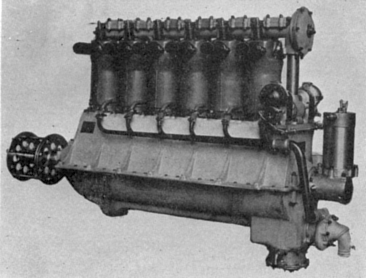 |
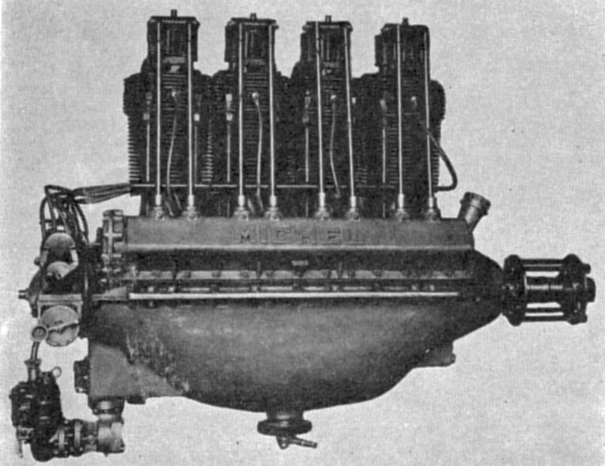
| A.M.7 (AEE) |
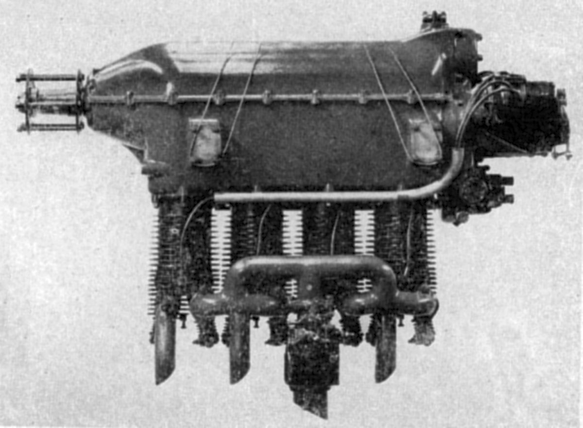
The A.M.7 was a water-cooled inline six that closely resembling the U.S. Liberty engine. Apparently, surplus Liberty cylinders were used, as the bore was 127.0 mm ( 5.00"), the stroke 177.8 mm (7.00"), the displacement was 13.514 l (824.68 in³) and compression ratio was 5.2:1. It normally developed 200 hp at 1,700 rpm and 217 hp at 1,850 rpm. Weight was 240 kg (529 lb). Fuel and oil consumptions were 0.484 and 0.044 lb/hp/hr. The upper and lower crankcase halves were aluminum alloy castings joined in the crankshaft plane. The crankshaft was supported in seven plain bearings. Special aluminum alloy pistons had six rings each. An aluminum housing bolted to the cylinders carried the overhead camshaft in seven aluminum bearings. A gear pump maintained pressure lubrication. Two S.E.V. magnetos provided dual ignition, and two Zenith 60J carburetors supplied the mixture. An S.M.N. starter engaged with the crankshaft rear end.
 |
 |
 |
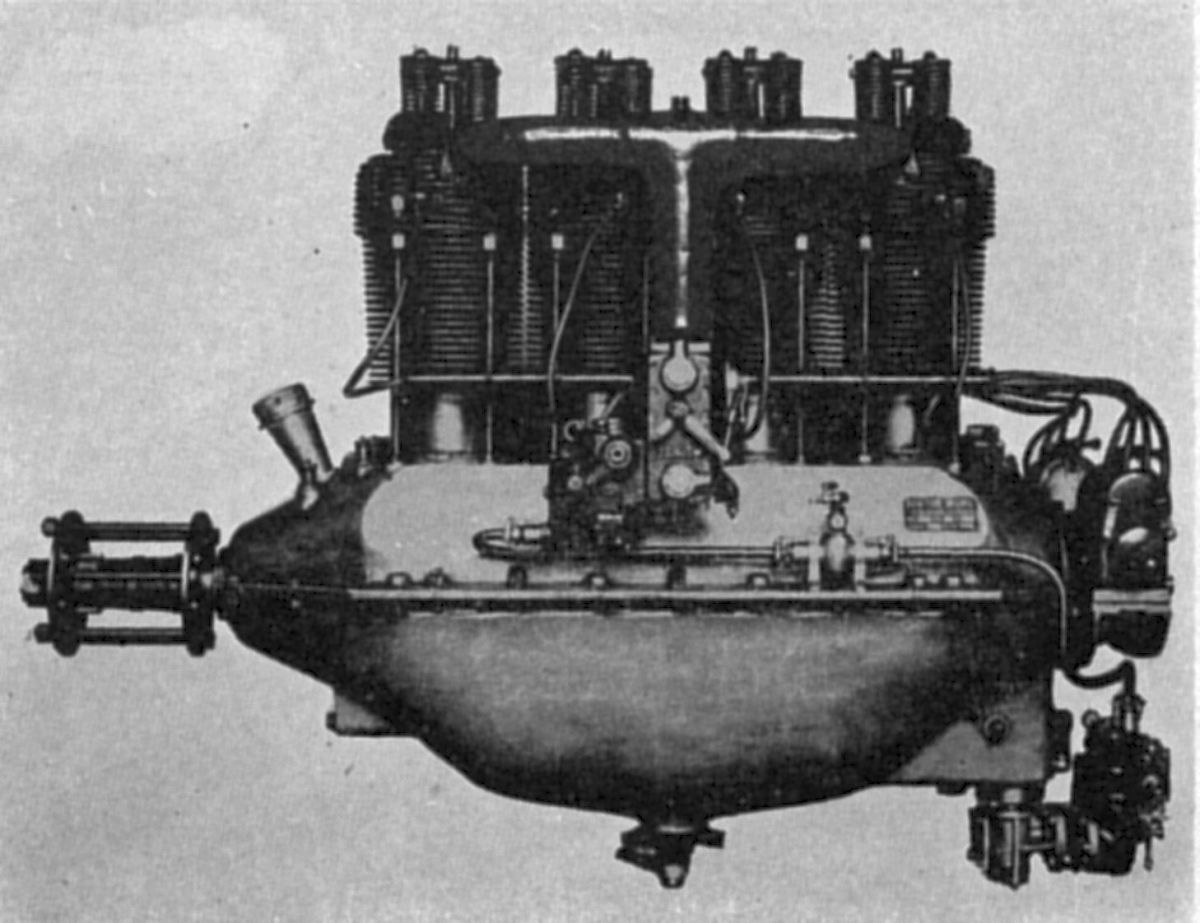
| A.M.14 (AEE) | ||
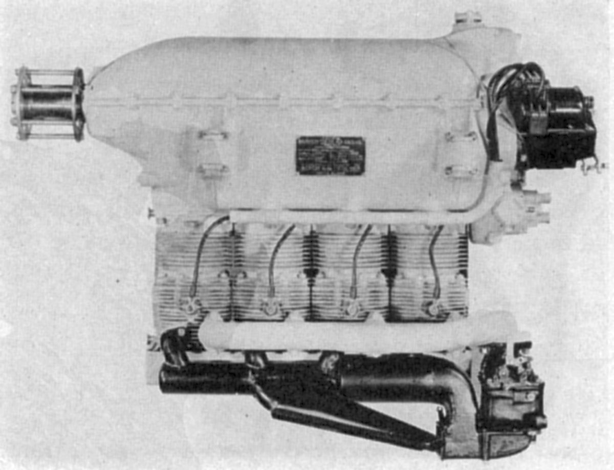
The A.M.14 was an air-cooled inline four developed for sport and training airplanes. The individual cast iron cylinders had integral cooling fins. The valves, which sat vertically in the head, were operated by push rods and rocker arms from a camshaft mounted in the upper crankcase side. The crankcase upper and lower halves were cast from aluminum alloy. The four-throw crankshaft was supported in five bronze-backed white-metal-lined plain bearings. The aluminum pistons had three compression rings above the piston pin and one oil scraper ring below. Connecting rods were made from chrome-nickel steel with the big ends lined with white metal. A large capacity centrifugal pump drew oil through a filter and delivered it to a service tank, which maintained pressure lubrication. The inlet pipes were heated by hot oil drawn from the crankcase. A Zenith 50J carburetor supplied the mixture, two S.E.V. magnetos furnished dual ignition.
The A.M.14 Type I had a 115 mm. (4.528") bore, a 150 mm (5.906") stroke, a 6.232 l (380.3 in³) displacement and 4.9:1 compression ratio. Its normal output was 80 hp at 1,700 rpm, and its maximum output was 90 hp at 1,850 rpm Fuel and oil consumptions were 0.506 and 0.0551 lb/hp/hr.
The A.M.14 Type II had a 125 mm (4.921") bore, 150 mm (5.906") stroke, 7.363 l (449.32 in³) displacement and 5.1:1 compression ratio. Its normal output was 100 hp at 1,600 rpm, and the maximum was 120 hp at 1,850 rpm. Weight was 161 kg (356 lb)
 |
 |
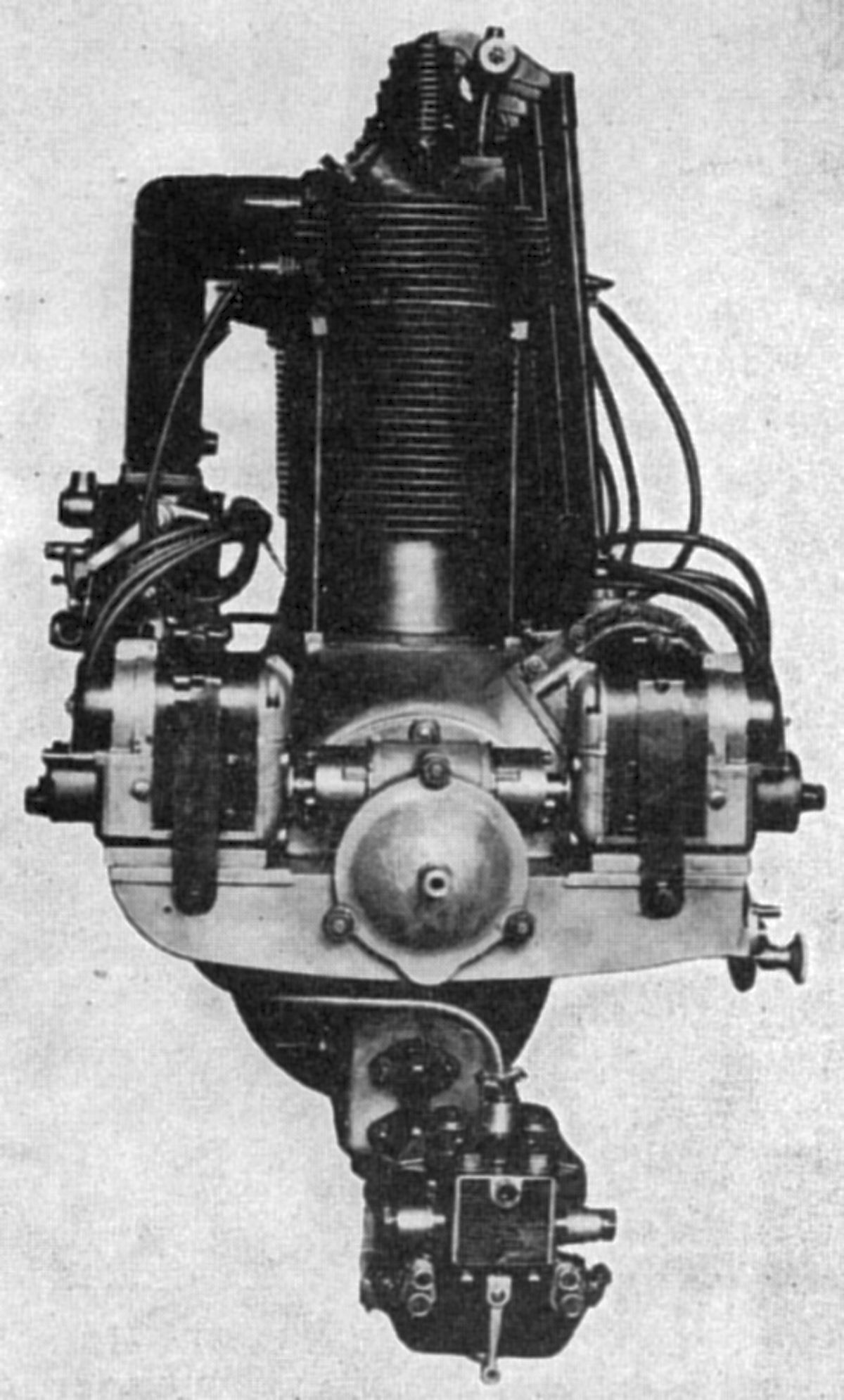
| A.M.16 (AEE) | |
The A.M.16 was a water-cooled inline six fitted with a compressor that maintained normal output at altitude. The crankshaft and connecting rods were carried upon roller bearings. The dynamically-balanced crankshaft of a special built-up construction was provided with five bearings. The valves were mechanically operated by two camshafts, and rocker levers compensated for thermal expansion. The propeller was driven through epicyclic reduction gears having 3:1 ratio. Complete electrical equipment provided radio, lighting, and starting. The upper and lower halves of the crankcase were aluminum castings fitted with steel sleeves that supported the crankshaft roller bearings. A gear-type oil pump was attached to the crankcase bottom. Oil was drawn from the crankcase lower half through a filter and then carried through a tube to the crankshaft and roller bearings. Pressurized oil was also carried via the hollow vertical camshaft drive shaft to lubricate the camshaft, valve guides, and rocker arms. Excess oil drained down through the vertical shaft housing to the crankcase. A water pump was driven from this vertical shaft. A Zenith carburetor was installed, and the mixture was delivered under pressure to the cylinders by a Cozette compressor. The cylinders consisted of separate sleeves fitted into aluminum jackets. The cylinder heads were made in pairs and attached to the jacket casting by four bolts against a copper-asbestos gasket. Aluminum alloy pistons were fitted with three rings each. The piston pins were fixed in the connecting rods but were free in the piston bosses. The connecting rods had H-section shanks with the big end hardened and ground for the roller bearing.
The A.M.16 Type I had a 55 mm (2.165") bore, a 70 mm. (2.756") stroke and a 0.998 l (60.90 in³) displacement. Normal output was 40 hp at 3,600 rpm and the maximum output (with compressor) was 75 hp at 5,000 rpm. Weight was 110 kg (242 lb).
The A.M.16 Type II had a 60 mm (2.362") bore, a 70 mm. (2.756") stroke and a 1.188 l (72.496 in³) displacement. Normal output was 50 hp at 3,600 rpm and the maximum output (with compressor) was 82 hp at 5,000 rpm. Weight was 118 kg (260 lb).
The A.M.16 Type III engine had a 65 mm. (2.559")bore, a 70 mm. (2.756") stroke and a 1.394 l (85.05 in³) displacement. Normal output was 55 hp at 3,600 rpm, and the maximum (with the compressor) was 87 hp at 5,000 rpm. Weight was 130 kg (286 lb).
Michigan Aero
The Michigan Aero-Engine Corporation of Lansing, Michigan, a subsidiary of the Michigan Screw Company, built the "Rover" engines designed by Harold E. Morehouse. This company was succeeded by the Lundberg Screw Products Company, which later sold the engine business assets to J. A. Roché. These engines were inverted air-cooled inline fours that first appeared during 1928.
 |
| R-236 (AEE) |
The Model R-236 had a 3.875" (98.425 mm) bore, a 5.000" (127 mm) stroke, a 235.86 in³ (3.865 l) displacement and a 5:1 compression ratio. It was rated 55 hp at 1,900 rpm, weighed 210 lb (95 kg), and received Department of Commerce Approved Type Certificate No. 25 on 8 Jun 1929. The individual cylinders were nickel-iron castings with integral cooling fins. The hemispherical combustion chamber carried two valves placed 25° to the cylinder axes and operated by push rods and rocker arms from a five-bearing camshaft on the crankcase right side. The camshaft was driven by spur gears at the rear. The rocker arms were supported by steel brackets attached to the cylinder heads. Valve ports faced opposite the valve mechanism. The inlet manifold connecting the four cylinders had a central connection for a duct leading from a rear-mounted carburetor. The cast aluminum crankcase featured four support pads. The four-throw crankshaft was carried in five plain bearings and a front-mounted ball thrust bearing. The bearings were secured by forged duralumin caps, the pan or top crankcase could be removed without disturbing the bearings. The trunk-type pistons were permanent-mould aluminum castings with a floating piston pin having bronze end buttons. Three compression rings above the piston pin and one oil scraper ring below it were fitted to each piston. The forged duralumin connecting rods with H-section shanks were fitted with bushings for the piston pin and had directly applied white metal at the big end. The gear-type oil pump contained a gearset for pressure feed and two gearsets to scavenge oil from either crankcase end. Two flange-mounted Scintilla magnetos, one with an impulse coupling, furnished dual ignition. A cowling and air scoops were standard equipment to properly direct the cooling air flow.
 |
| R-267 (AEE) |
The Model R-267 was an enlarged and refined version of the earlier Rover. With a 4.125" (104.775 mm) bore, 5.000" (127 mm) stroke, 267.28 in³ (4.380 l) displacement, and 5:1 compression ratio, it had a 232 lb (105 kg) dry weight (complete with propeller hub, exhaust system, carburetor air-heater, cooling air scoop, and mounting lugs). Fuel and oil consumptions were 0.55 - 0.58 and 0.010 – 0.015 lb/hp/hr. It was rated 75 hp at 1,975 rpm and was issued Department of Commerce Approved Type Certificate No. 37 on 4 Jan 1930. Principal design changes included a larger bore, cast aluminum alloy cylinder heads with bronze valve seats and spark plug bushings shrunk and expanded in position. These heads were shrunk and bolted to nickel-iron barrel castings with integral cooling fins using copper-asbestos gaskets to make a permanent assembly. The main crankshaft journals and connecting rod big ends were provided with white-metal-lined steel-back bearings. The valve mechanism was completely enclosed by a single stamped steel housing. The engine was furnished with a stamped steel exhaust manifold, incorporating a hot air muff that connected with the carburetor air heater. The engine was 47.25" (1,200 mm) long, 11.125" (283 mm) wide and 31.875" (810 mm) high.
Miller
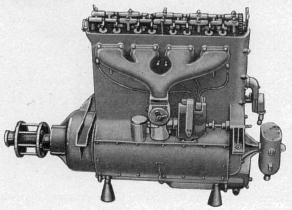
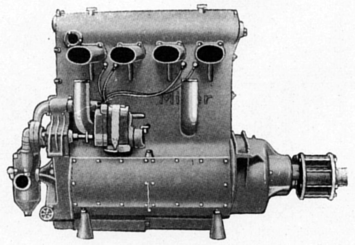
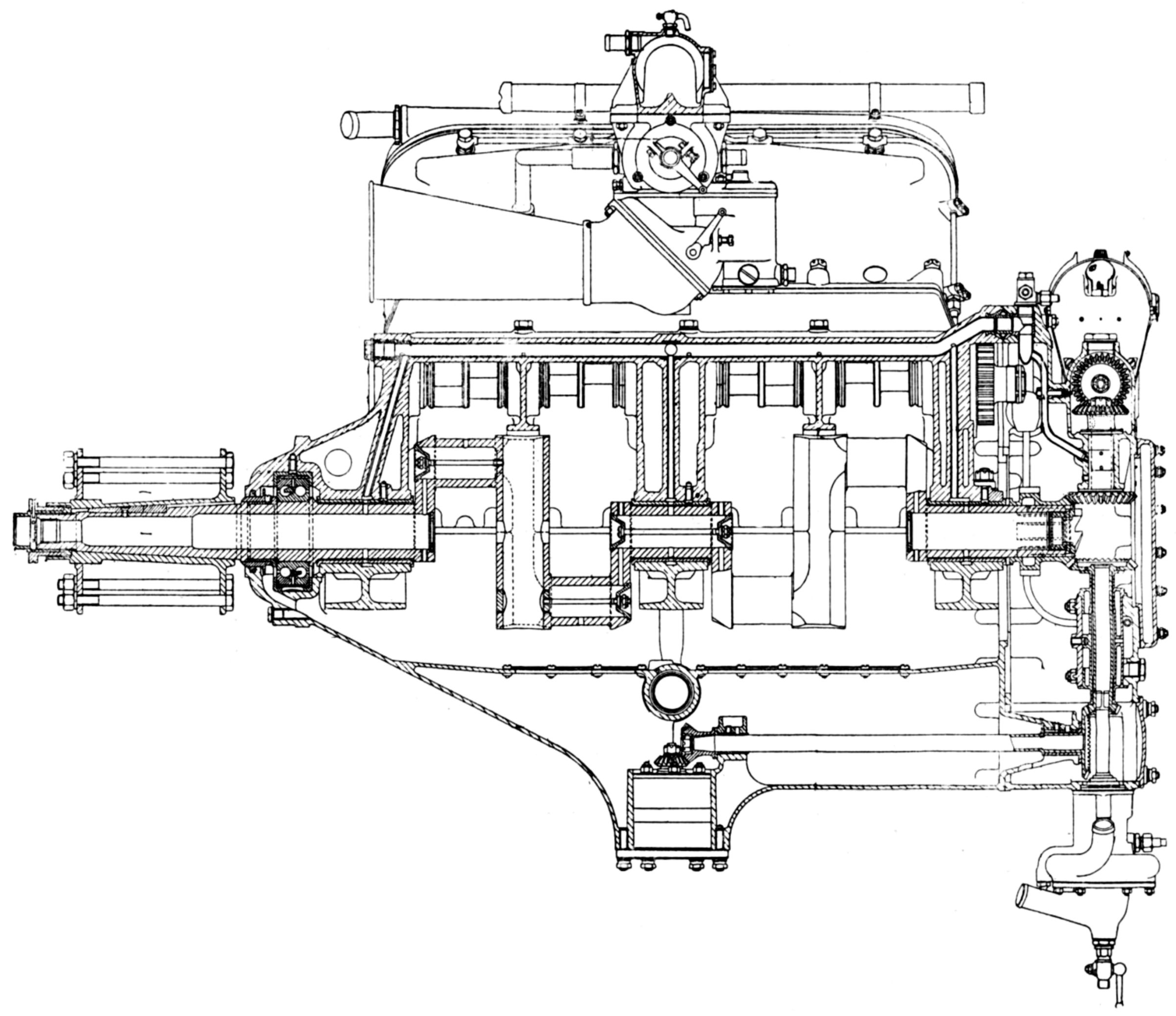
The Harry A. Miller Manufacturing Company of Los Angeles, California, manufacturers of racing automobile engines and carburetors, also constructed airplane engines. Its first was a water-cooled vertical four with a 4.000" (101.6 mm) bore, 7.000" (177.8 mm) stroke and 351.86 in³ (5.766 l) displacement normally rated 125 hp that developed 139 hp at 2,600 rpm and 155 hp at 2,100 rpm. A reduction gear with a 1.8519:1 ratio was employed. Completely machined vanadium cast-iron cylinder sleeves were inserted in the water jackets and packed with rubber ring gaskets. The cylinder head, which rested upon the sleeves and held them in place, was cast from aluminum alloy and contained cast-in-place cast-iron valve seats. The water jacket around the cylinder barrels was cast integral with the crankcase. The counterbalanced crankshaft was made in two parts, with a center joint that used a taper, key, and nut, thus facilitating installation of three annular double-row ball bearings. The tubular-shank connecting rods had four-bolt caps and piston pins clamped in the upper ends. There were four valves per cylinder with the valve mechanism enclosed and operating in an oil bath. The camshaft, driven by a spur gear train, was composed of four cam units and five annular ball bearings mounted on a tubular shaft. Each cam unit comprised an inlet and exhaust cam with their followers. The follower cam caused the rocker to follow the main cam, giving positive rocker movement. The aluminum alloy pistons were fitted with two rings. The planetary reduction gear used double-row annular ball bearings throughout. Two magnetos provided dual ignition, and the dry-sump lubrication system used a gear pump to circulate the oil. Dry weight was 410 lb (186 kg), and the engine was 41" (1,041 mm) long, 18.25" (464 mm) wide and 34" (864 mm) high.
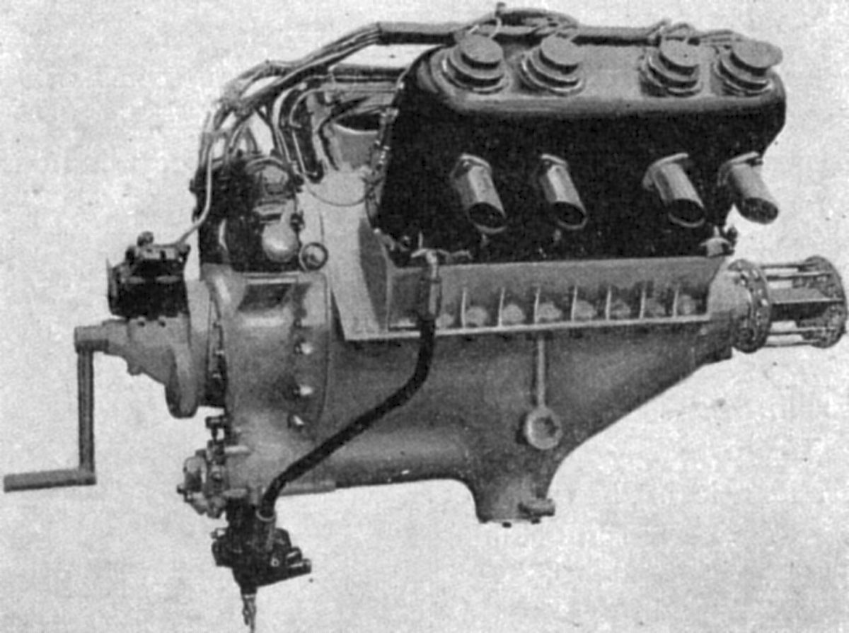
A water-cooled 60° V-12 with a 5.000" (127 mm) bore, 6.000" (152.4 mm) stroke displaced 1,413.72 in³ (23.167 l). Twelve vanadium cast-iron sleeves were inserted into a single aluminum alloy block. The valves were situated horizontally with respect to the cylinder axis and were operated through rockers from a single camshaft in the Vee. The valves had a clear diameter of 2.25" (57.15 mm) and a 0.5" (12.7 mm) lift. The aluminum alloy pistons were fitted with three top rings. The crankshaft ran in seven main bearings. Four 1.75" (44.45 mm) Miller carburetors supplied the mixture, and two Dixie twelve-cylinder magnetos the ignition. The dry sump lubrication used one pressure and two scavenge gear pumps.
An experimental water-cooled inline eight with 4.375" (111.125 mm) bore, 5.250" (133.35 mm) stroke, 631.39 in³ (10.347 l) displacement and 6:1 compression ratio was rated 250 hp and weighed 450 lb (204 kg).
During early 1928, Miller was developing an air-cooled eight-cylinder horizontally-opposed engine that was to deliver 130 hp at 2,000 rpm and weigh 300 lb (136kg).
Miller was reported to have two geared air-cooled 45° V-16s under development. The smaller of these, known as the Miller 464, had a 3.250" (82.55 mm) bore, 3.500" (88.9 mm) stroke, 464.56 in³ (7.61 l) and 7:1 compression ratio that was to develop 600 hp at 5,000 rpm and weigh 500 lb (227 kg). Miller carburetors were used, and two Bosch magnetos supplied dual ignition. It was 66" (1,676 mm) long, 22" (559 mm) wide and 31.5" (800 mm) high.
The larger engine, known as the Miller 1200, had a 4.500" (114.3 mm) bore, a 4.750" (120.65 mm) stroke and a 1,208.73 in³ (19.81 l) displacement. Its was rated 2,000 hp at 5,500 rpm and weighed 1,250 lb (567 kg). It was 90" (2,286 mm) long, 25" (635 mm) wide and 37" (940 mm) high.
 |
 |
| Miller 255 (A39) | |
The Miller 255 was a geared water-cooled inline four with a 4.250" (107.95 mm) bore, 4.500" (114.3 mm) stroke, 255.35 in³ (4.18 l) displacement and 10:1 compression ratio. It was rated 250 hp at 5,500 rpm, weighed 300 lb (136 kg), was 27.5" (699 mm) long, 13" (330 mm) wide and 21.25" (540 mm) high.
Minerva
During 1924, Société Anonyme Minerva Motors, well-known manufacturers of automobiles in Antwerp, Belgium, began developing what it claimed was the first Knight sleeve-valve airplane engine from the Minerva automobile engine by introducing certain design innovations and lighter alloys.
 |
 |
 |
| Minerva 8V-150 (A39) | ||
The Minerva 8V-150 was a water-cooled 90° V-8 with a 100 mm (3.937") bore, 150 mm. (5.906") stroke, 9.425 l (575.15 in³) displacement and 5.3:1 compression ratio. Its normal rating was 140 hp at 1,600 rpm and 160 hp at 1,800 rpm. Weight was 238 kg (524 lb), and fuel and oil consumptions were 0.502 and 0.024 lb/hp/hr. The Belgian Government accepted the engine for use in training ships, but when put into production, the bore was increased to 105 mm (4.134") to give a 10.391 l (634.1 in³) displacement, and the compression ratio was raised to 5.5:1. The production engine developed 175 hp at 1,800 rpm.
A 600 hp V-12 was designed using 8V-150 features. Each cylinder row was cast in one block of Alpax, a ductile aluminum-silicon alloy. This casting included intake passages and cooling water jackets. The outer sleeve valve was aluminum bronze and the inner sleeve valve steel. A special method for mounting lugs on the sleeves was employed. An improved method of circulating water around the spark plugs and cylinder heads was introduced, and the cylinder head gasket was isolated from the water. The cylinder heads, also of Alpax, each carried two spark plugs screwed into bronze bushings that were cast into the head and provided with a shoulder on the inner face. The four-throw crankshaft was supported in three plain bearings and a front-mounted double-row ball thrust bearing. The three plain bearings were held between the upper crankcase half and bearing caps. The upper crankcase-half was an aluminum casting with a cast-in steel tube for conducting pressurized oil to the main bearings and the five aluminum bearings supporting the sleeve-drive eccentric shafts, which were driven through spur gears located at the engine rear. The crankcase lower half, also an aluminum casting, served as an oil pan and carried oil pumps that were driven from a horizontal shaft by bevel gears. A rear housing and gear case covered the driving gears, and carried the driving gears and shafts for the magnetos, fuel pump and water pump. Fork-and-blade connecting rods with tubular shanks were forged from chrome-nickel steel. The forked rod had a hard phosphor bronze white-metal-lined bushing bearing upon the crankpin. The inner rod bore directly upon the fork rod bushing and carried a tube leading oil to the case-hardened piston pin. The pistons were Elektron castings fitted with four narrow compression rings. Pressure feed lubrication was used throughout, with about 28 psi maintained in the main feed line. The upper of the two pumps drew oil from an outside tank and delivered it through a large capacity filter and main galleries to the main bearings, eccentric shafts, and magneto and water-pump shafts. Two bypasses to the cylinder walls and the sleeve heads were connected with the carburetor throttle and only opened when half-throttle was reached, thereafter increasing up to full-throttle position. Excess oil draining into the base chamber was returned to the tank by a scavenging pump. A bevel pinion at the crankshaft rear drove two vertical shafts, the upper one in turn driving two Scintilla AG8 magnetos through bevel gears, and the lower one the water and oil pumps. The water pump had no packing gland, water tightness being secured by the construction of the turbine and by a cone and cup. Contact between the two was maintained by a spring and a ball thrust bearing running in oil. A double Zenith carburetor located in the Vee supplied the mixture to a manifold joining the two blocks; the manifold was heated by water circulation. Air entered the carburetor through a forward-facing funnel . Starting was facilitated by an Athmos injector, and a hand crank that could be geared down to meet special requirements.
Morehouse
The first Morehouse engine was built by the Steel Products Engineering Company of Springfield, Ohio during late 1923, and was used by the U. S. Army Service Engineering Division Propeller Branch for experimental work. This engine was designed by Harold E. Morehouse, who later built a larger model and sold the design to the Wright Aeronautical Corporation where it became known as the Wright-Morehouse engine. Wright then sold the design to the Lincoln Aircraft Corporation of Lincoln, Nebraska, where it became known as the Lincoln Rocket.
 |
 |
| Morehouse M-42 (A39) | |
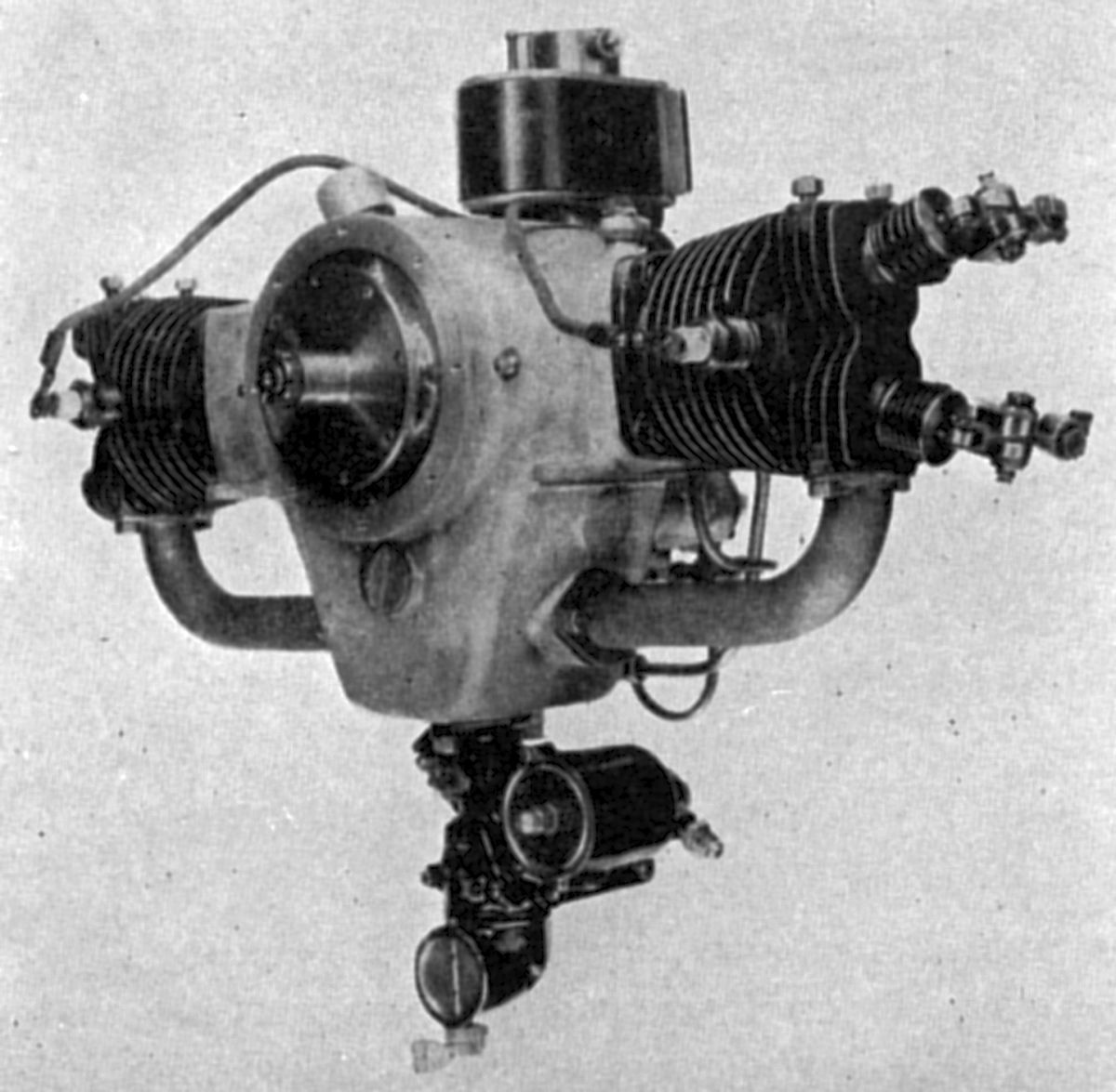
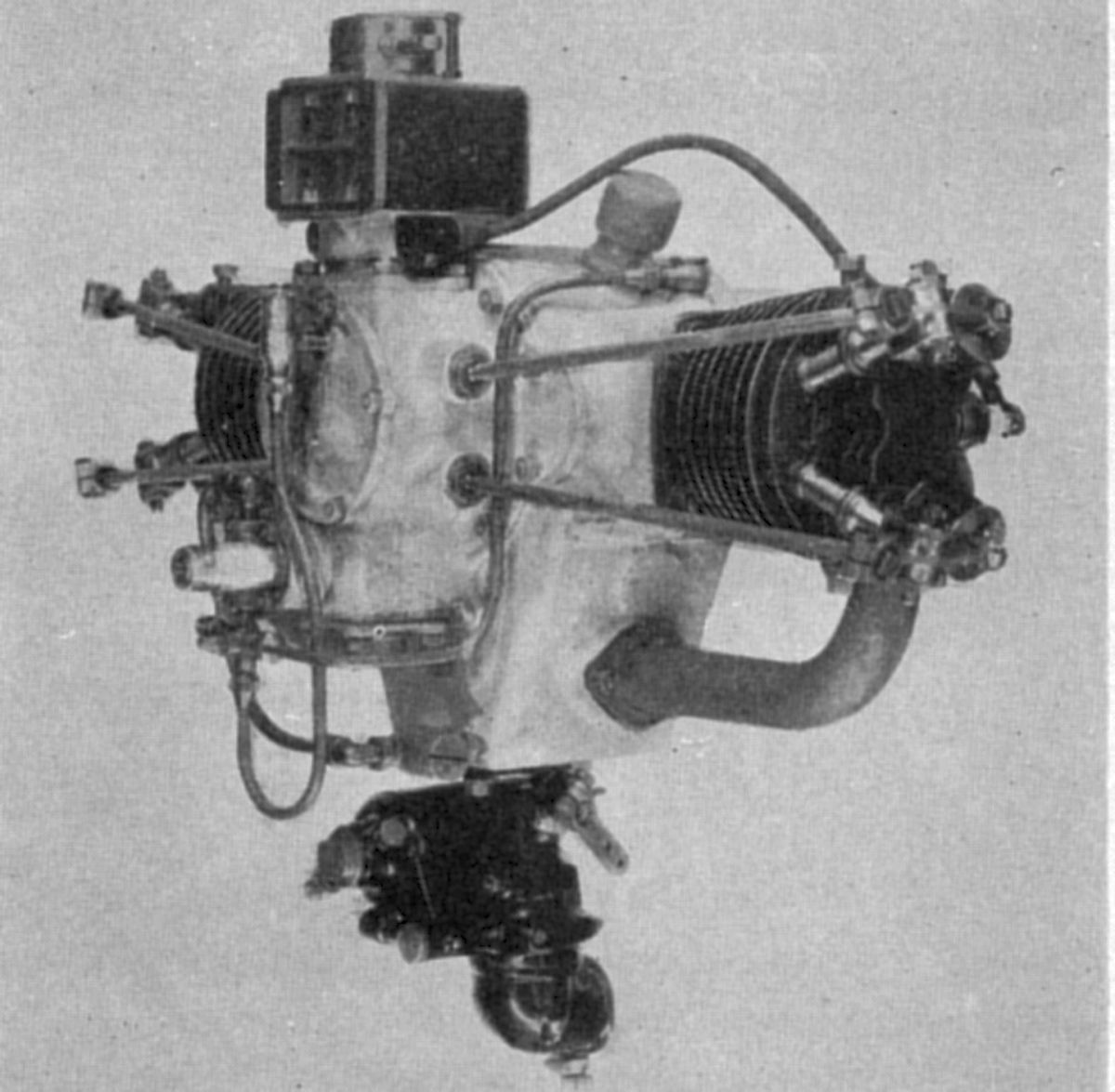
The M-42, Morehouse's first engine, was an air-cooled two-cylinder horizontally-opposed type with a 3.00" (76.2 mm) bore and stroke, 42.41 in³ (0.695 l) displacement and 5.1:1 compression ratio. This engine delivered 12 hp at 2,000 rpm and 20 hp at 3,000 rpm. Dry weight was 51.4 lb (23.3 kg). It was 12.375" (314 mm) long, 24.75" (622.3 mm)wide, and 19.0" (483 mm) long. The cast iron cylinders had integral cooling fins. Two interchangeable tulip-shaped valves, inclined 20° to the cylinder axes, seated directly into the hemispherical combustion chamber head. The valve port clear diameter was 1.1875" (30.15 mm), the valve lift was 0.281" (7.14 mm), and the 45° seats were 0.125" (3.18 mm) wide. The valves were operated through rocker arms, push rods and mushroom-type followers from a vertical camshaft carried in bronze bushings in a case bolted to the crankcase rear. The rear case covered the large opening through which the connecting rods and crankshaft were assembled. Inlet valves opened at top center an closed 48° late; the exhaust valves opened 48° early and closed at top center. The cast aluminum alloy pistons had flat heads and were fitted with three rings above the 0.700" (17.78 mm) piston pin, which was fitted with bronze or aluminum end buttons. The two-throw counterbalanced crankshaft was carried upon ball bearings. By the use of narrow roller bearings on the crankpin, the total cylinder axis offset was only 0.625" (15.875 mm). The drop-forged steel connecting rods were fitted with removable hardened steel sleeves in the big ends, which served as outer races for the rollers. A bronze bushing at the rod's small end bore the piston pin. The aluminum crankcase featured an integral oil sump, which could function either horizontally or vertically by slight engine changes. The crankcase had two pilots for each cylinder, one near the cylinder skirt inner end and the other about half way up the barrel; and these formed a closed compartment with the cylinder in position. Oil was fed directly into these compartments by a gear pump, and a hole in the top of each barrel passed it to the pistons. The crankshaft and connecting-rod bearings were lubricated by the splash thrown into the crank compartment by the pistons. Surplus oil served to cool the cylinder barrel and was returned to the oil sump by a separate passage. Y-shaped induction passages were cast into the oil sump and the mixture was led to each cylinder by a separate flanged pipe from a special Stromberg carburetor. A single Bosch magneto was mounted vertically and driven from the upper camshaft end. The camshaft was driven from the crankshaft by bevel gears, and at its lower jaws facilitated starting with a hand crank. A gear oil pump was driven from the camshaft by spiral gears, and the pump shaft, which extended through the casing, provided a tachometer drive. A flange was provided on the crankcase front to attach an optional reduction gear.
 |
 |
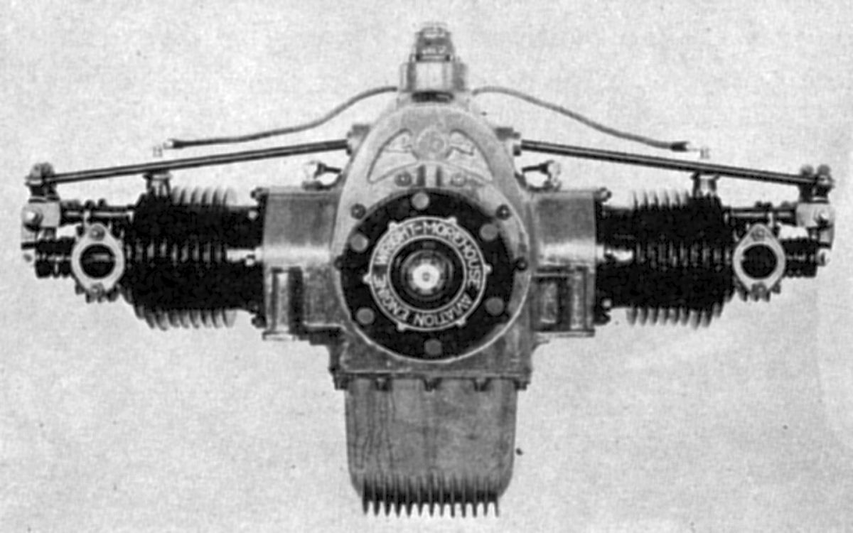
| Wright-Morehouse WM-80 (A39) | |
The WM-80, a larger and more refined air-cooled horizontally-opposed two-cylinder introduced in 1925, later became known as the Wright-Morehouse engine. With a 3.750" (95.25 mm) bore, 3.626" (92.075 mm) stroke and 80.01 in³ (1.312 l) displacement, it developed 28 hp at 2,500 rpm and weighed 85 lb (38.5 kg), or 99 lb (44.91 kg) with the 2.74:1 propeller reduction gear. The cast-iron cylinders had integral cooling fins, with the skirts projecting into the aluminum crankcase to form a closed compartment similar to the smaller model. The crankcase assembly opening was in front, and the camshaft was assembled from the crankcase rear, being parallel to and above the crankshaft. The 3-quart (2.8 l) oil sump was a separate aluminum casting attached to the crankcase bottom. Cooling fins were cast onto the sump bottom, which also provided for a filter screen and an oil thermometer. The counterbalanced two-throw crankshaft had narrow crankpins to minimize cylinder offset. Each aluminum alloy piston was fitted with three compression rings and one oil-scraper ring. The timing gears consisted of three spur gears; the crankshaft gear drove an idler at half speed, and the idler drove an equal-diameter gear attached to the camshaft end. A single Scintilla magneto was driven from the camshaft end. The cams operated against mushroom type cam followers, carried in crankcase bushings, which actuated push rods and rocker arms held to the cylinder head by brackets and single studs. The inlet valves opened 10° early and closed 50° late; the exhaust valves opened 58° early and closed 14° late. A 1.25" (31.75 mm) Stromberg carburetor delivered the mixture via separate pipes to each cylinder.
Murray-Willat
Starting in 1911, Joseph J. Murray began designing an air-cooled, valveless, 2-stroke, supercharged rotary engine. The first model tested early in 1912. These were developed by the Murray-Willat Company, and built by the American Motors and Aviation Company. The Murray-Willat engine design is probably the earliest American supercharged aircraft engine. Murray engines were produced until 1914.
The Murray-Willat engines incorporated an integral supercharger. Open exhaust ports at each cylinder bottom permitted fairly complete scavenging by the air blast across the piston at the end of each stroke. The cylinders were machined from solid forged-steel billets with integral head and cooling fins. In addition to the large exhaust ports, there were small inlet ports that registered with deflectors in the piston tops. These directed the charge toward the cylinder top, thus preventing it from escaping through the exhaust ports. The crankcase was machined from solid steel forgings, the two halves clamping the cylinders between them. The connecting rods were attached to a spool that was carried on two ball bearings. Pressurized oiling was from a triple outlet pump; one outlet forced oil to the connecting rod bearing, another sprayed the crankcase, lubricating all interior engine parts, while the third forced an oil spray into the supercharger, mixing oil with the incoming mixture and eliminating the need to mix oil with fuel.
The first model had six cylinders with a 75 mm (2.953") bore, 90 mm (3.543") stroke and the 2.386 l (145.58 in³) displacement. It produced 25 hp at 1,200 rpm. Fuel and oil consumptions were 0.615 lb/hp/hr and 2.8 lb/hr. The overall diameter was 25.98" (660 mm) and the weight was 60 kg (132 lb). The supercharger was a Roots type, using two large gears meshing with each other and running in a case that was almost as large as the crankcase.
The second model featured several improvements, such as a positive pressure supercharger running at crankshaft speed. This six-cylinder rotary had a 100 mm (3.937 mm) bore, 130 mm (5.118") stroke and 6.126 l (373.83 in³) displacement. It was rated 70 hp at 1,200 rpm and weighed 118 kg (260 lb). Outside diameter was 737 mm (29").
The third engine improved upon the first design, incorporating an improved vane-type supercharger; it was rated 30 hp.
 |
| Ajax (A39) |
The Murray Ajax was a larger and refined version of earlier engines. With a 111.125 mm (4.375") bore, 136.525 mm (5.375") stroke, 7.943 l (484.71 in³) displacement and 5.3:1 compression ratio, it was rated 80 hp at 1,250 rpm and weighed 95 kg (210 lb). Fuel and oil consumptions were 0.52 and 0.044 lb/hp/hr. Outside diameter was 914 mm (36").
The eight-cylinder Murray Atlas had a 123.825 mm (4.875"), a 120.65 mm 4.750" stroke (the full stroke being 6"), an 11.623 l (709.28 in³) displacement and 5.2:1 compression ratio. Rated output was 120 hp at 1,250 rpm. Weight was 118 kg (260 lb) and outside diameter was 914 mm (36"). Fuel and oil consumptions were 0.52 and 0.044 lb/hp/hr.
References
Angle, Glenn D, ed. Aerosphere 1939 (New York, New York: Aircraft Publications, 1940).
Anble, Glenn D, ed. Airplane Engine Encyclopedia (Dayton, Ohio: Otterbein Press, 1921).
Meyer, Robert B. Jr., ed. Langley’s Aero Engine of 1903 (Washington, DC: Smithsonian Institution Press, 1971.
Wikipdeia Maybach Mb.IVa
Image Sources: A39 = Aerosphere 1939; AEE = Airplane Engine Encyclopedia; Flt = Flight Magazine; NARA = U.S. National Archives and Records Administration; UKNA = United Kingdom National Archives.
Send mail to
![]() with questions or comments about this web site.
with questions or comments about this web site.
![]()