Turbosupercharger Control Systems
Part 1: The Eclipse Turbosupercharger Regulator
Compiled by Kimble D. McCutcheon
Published 1 Oct 2020; Revised 2 Aug 2023
Introduction
Boeing B-17 and Consolidated B-24 bombers were equipped with a General Electric Type B-2 or B-13 turbosupercharger for each of their four engines. Each turbosupercharger required a control system that was capable of maintaining the commanded level of boost. Early aircraft were equipped with Eclipse regulators that controlled the turbosupercharger waste gate using engine oil pressure. Later aircraft used Minneapolis-Honeywell electric control systems. Much of this discussion is specific to B-24 aircraft, but other turbosupercharger installations were similar.
Turbosupercharger Installation
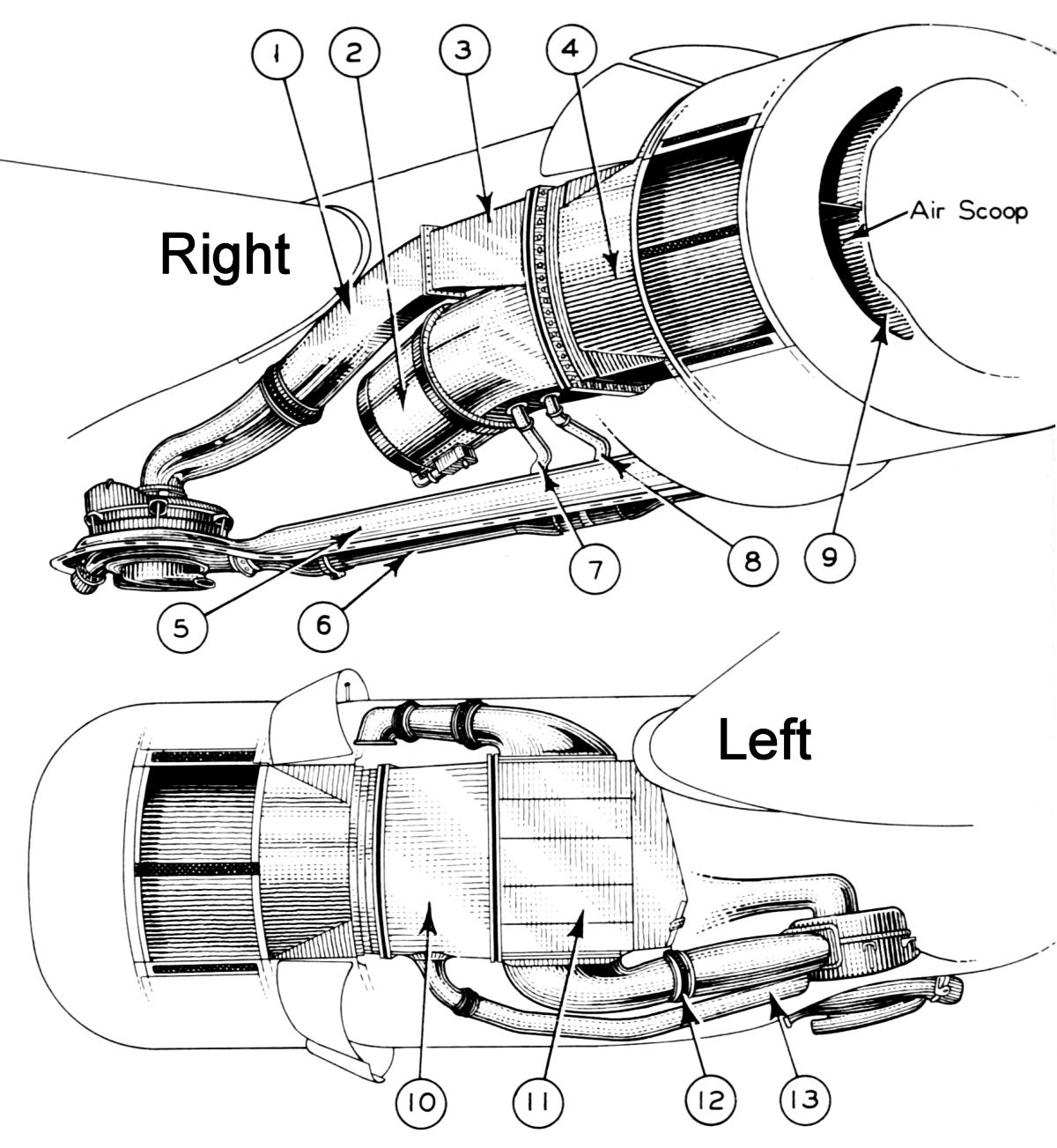
The turbosupercharger installation consisted of a turbosupercharger, an intercooler, and the ducting that connected them to the engine. Air entered the nacelle via a scoop on the port side after which it was split into a stream for the oil cooler and another for induction air. Some of the oil cooler air was diverted to shrouds surrounding the exhaust tail pipe, where it helped prevent heat from the hot exhaust pipe from affecting the airframe. The induction air passed through an alternate air control valve, operated by a control in the flight deck, which selected either unfiltered ram air or filtered air that was taken from inside the nacelle. The induction air, after being compressed by the turbosupercharger, was cooled by the air-to-air intercooler and ultimately presented to the carburetor inlet. Air entering the nacelle via a scoop on the starboard side was used to cool the intercooler and turbosupercharger. Carburetor air inlet temperature was controlled by shutters on the intercooler exit, which were connected to a flight deck control.
|
|
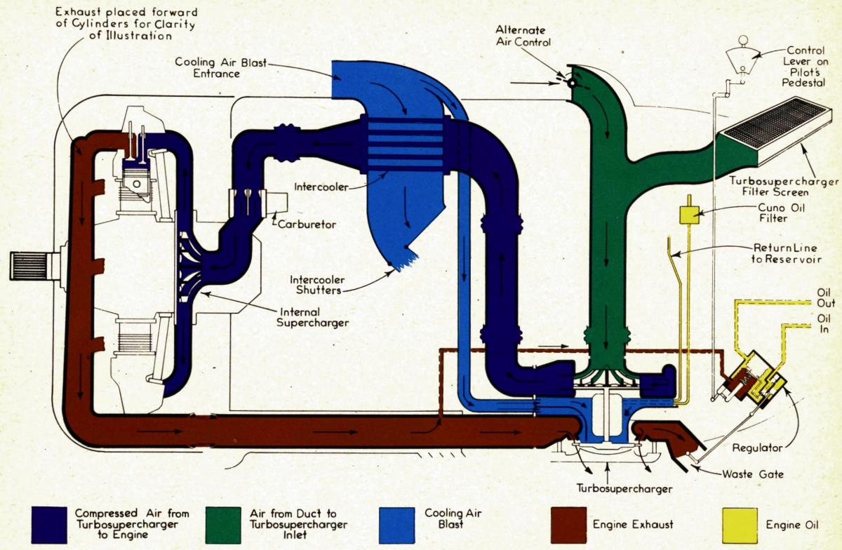
| Fig.1. B-24 Air Duct System. (1) Induction Air Duct; (2) Oil Cooler; (3) Induction Air Duct; (4) Starboard Main Air Duct; (5) Exhaust Tail Pipe Shroud; (6) Exhaust Tail Pipe; (7) Exhaust Tail Pipe Shroud Blast Tube; (8) Exhaust Tail Pipe Shroud Blast Tube; (9) Starboard Air Duct Inlet Scoop; (10) Port Main Air Duct; (11) Intercooler; (12) Turbosupercharger to Intercooler Air Duct; (13) Turbosupercharger Cooling Air Duct. | Fig. 2. B-24 Turbosupercharger Installation Schematic, Eclipse Regulator |
Turbosupercharger
The turbosupercharger furnished compressed air to the engine induction system at greater than sea level pressure (approximately 30 inHgA) during takeoff and climb, and at sea level pressure at altitude. The turbosupercharger consisted of a turbine, driven by engine exhaust gas pressure, that was attached to a centrifugal compressor. As aircraft altitude increased, the turbosupercharger spun faster, thereby supplying air at sea-level pressure up to its critical altitude, determined by turbine wheel structural limitations.
Turbine wheel speed was controlled by a waste gate, which, when open, allowed engine exhaust to escape, and, when closed, forced all engine exhaust through the turbine. The waste gate was constructed of stainless steel and designed so that little effort was required by the regulator to open or close it.
Cool air taken from the turbosupercharger cooling air duct (13 in Fig. 1) was directed against the turbosupercharger through a blast tube extending along the engine mount port side. This tube was slotted at the aft end and straddled the turbosupercharger shroud edge and the baffle ring. Part of the air was directed against the turbine wheel hub, and the rest to the lower bearing case.
The turbosupercharger oil system comprised a dedicated oil filter, a pressure pump and a scavenge pump. Dynamically-balanced gerotor type pumps were used for both. The scavenge pump volumetric capacity was greater than pressure pump element. The pressure pump drew oil from the engine oil reservoir through a filter and supplies pressurized oil to the turbosupercharger bearings. Discharged oil was pumped from the bearing chamber by the scavenging pump. A standard tachometer drive was provided on the outer end of the pump shaft; this drive was not used with Eclipse regulators but was used with M-H governors.
All pump bearings were sleeve-type and were lubricated by pump discharge pressure. A dual seal at the pump shaft outer end prevent both air and oil leakage.
 |
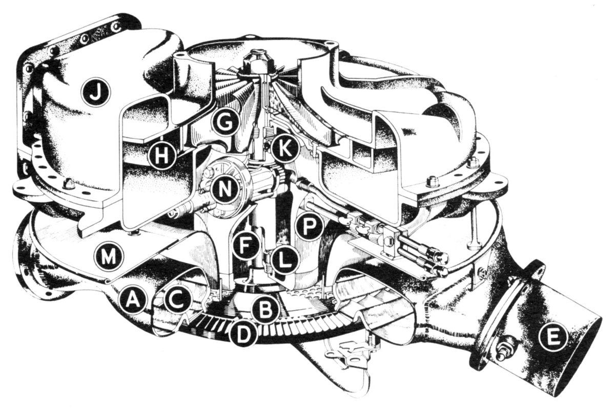 |
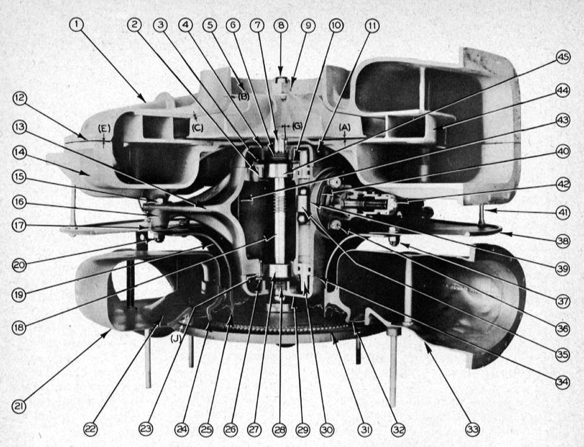
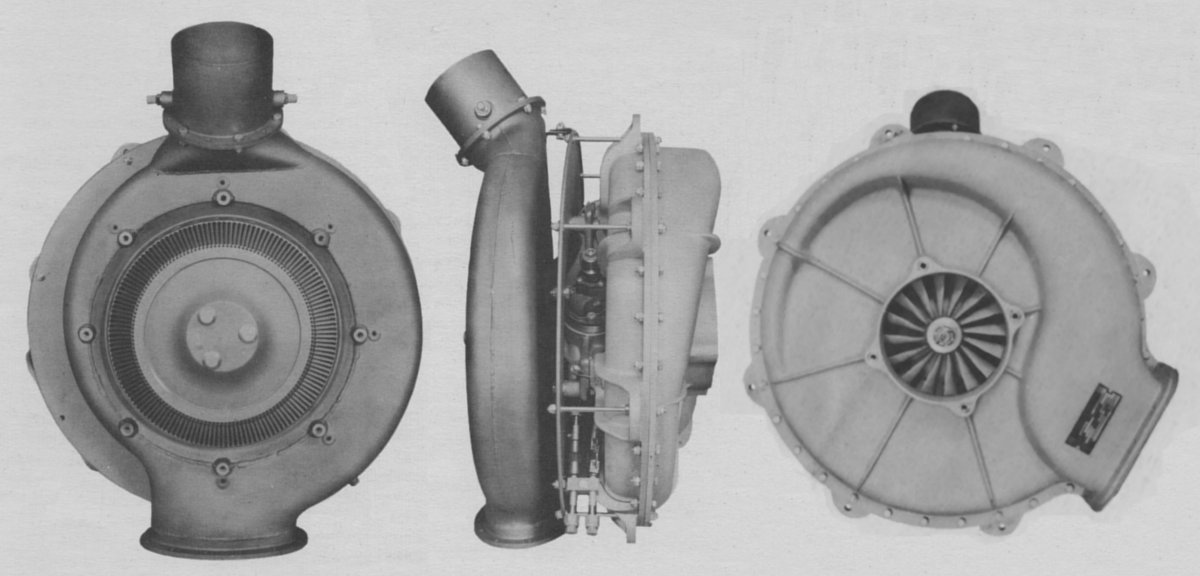
| Fig. 3. The turbocharger consisted of an electric-welded stainless steel turbine housing (21), a centrifugal air compressor contained in a cast aluminum housing (1), and a gear type lubricating pump (42). The turbine got its operating power from engine exhaust gas, which was conducted through the exhaust tail pipe to the turbine nozzle box (22), from where it was directed against the turbine bucket wheel (31) through nozzles (32). The centrifugal compressor was driven by the turbine wheel, with the compressor impeller (5) and the turbine wheel (31) mounted on the same shaft (8). | Fig. 4. The exhaust tail pipe connects to the Nozzle Box (A), which is directly above the Turbine Wheel (B). Hot gasses escape from the Nozzle Box through Fixed Nozzles (C), which increase gas velocity before it flows through the Turbine Buckets (D). Turbocharger speed is controlled by Waste Gate (E), which dumps excess exhaust gas overboard. Power developed by the turbine is transmitted via Shaft (F) to the centrifugal compressor Impeller (G), which is mounted at the opposite end of Shaft (F). The Impeller (G) and Diffuser (H) are enclosed in a Compressor Casing (J), which collects compressed air from the Diffuser (H). The rotating assembly is supported by a Ball Bearing (K), which takes thrust loads, and a Roller Bearing (L), which allows the Shaft (F) to expand. A Baffle Ring (M) distributes cooling air between the Nozzle Box (A) and Compressor Casing (J). Turbosupercharger lubrication is via a built-in Oil Pump (N), which is driven by a worm gear on Shaft (F). A Bearing-and-Pump Casing (P) houses the bearings and pump. |
 |
 |
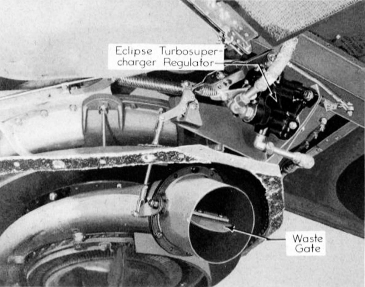 |
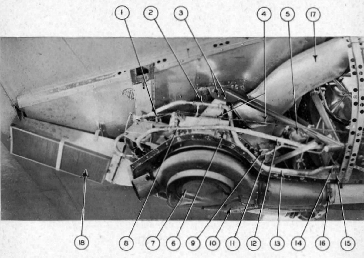
| Fig. 5. Turbosupercharger Bottom, Side and Top Views | Fig. 6. B-24 Turbosupercharger Installation, Starboard Aft View. (1) Turbosupercharger Mounting Bracket; (2) Regulator Oil Pressure Line; (3) Turbosupercharger Mounting Bracket Bolts; (4) Regulator Control Cables; (5) Turbosupercharger Oil Filter; (6) Turbosupercharger Baffle; (7) Turbosupercharger Cooling Cap; (8) Regulator Oil Return Line; (9) Turbosupercharger Lube Oil Inlet Line; (10) Turbosupercharger; (11) Turbosupercharger Lube Oil Outlet Line; (12) Regulator Oil Return Line; (13) Regulator Oil Pressure Line; (14) Regulator Oil Pressure Line Fitting; (15) Former Ring; (16) Exhaust Tail Pipe Lock Ring; (17) Induction Air Duct; (18) Induction Air Filter. | Fig. 7. Turbosupercharger Regulator and Waste Gate |
Eclipse Type A-13 Regulators
Eclipse regulators, mounted near the turbosupercharger waste gate, were controlled from the pilot's pedestal by means of levers, cables, rods, and bell cranks. Please refer to Figure 8 for the following discussion.
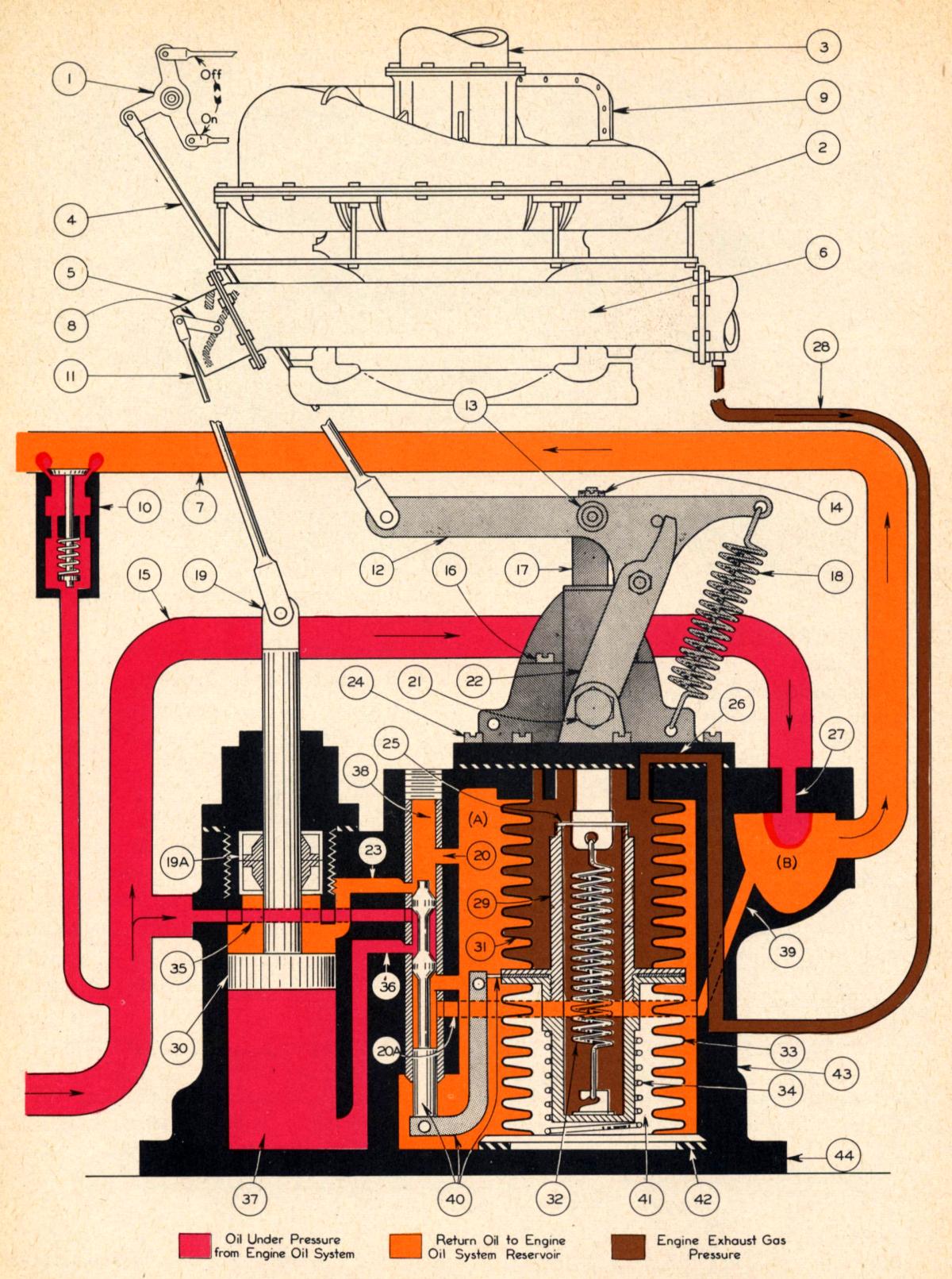 |
| Fig. 8. Turbosupercharger Regulator – LOCKOUT Position |
The cast magnesium regulator main body (43) incorporated tapped ports for tubing connections, drilled passages for oil flow, and a bronze pressure control valve sleeve.
The control valve plunger and bellows assembly consisted of a pressure control valve rod and center plate assembly (40), an exhaust pressure bellows (31), a sealed vacuum bellows (33), a range shifter tension rod (17), and springs (32) and (34).
The mounting flange assembly (44) bolted directly to the main housing and served as a clamp for the vacuum sealed bellows. A cork gasket (42) was placed between the mounting flange and the bellows.
The regulator cover assembly served as a guide for the range shifter tension rod (17) and contained a seal to prevent leakage from the exhaust pressure bellows (31). It also supported the control lever by means of two bearing screws (21).
The control lever assembly (12) operated the range shifter tension rod (17) through the crosshead (13), which was attached to the tension rod by the castellated nut (14). The lever pivoted about the crosshead and was supported by two arms (22) that were attached to the cover by two bearing screws (21). The spring (18), anchored to the bellows cover, was hooked also to one end of the lever (12) and balanced the range shifter spring (32) tension on rod (17).
The servo piston (30) was located in the cylinder (37). Shaft (19) was provided with a seal (19a) to prevent oil leakage out of the cylinder and air leakage into the cylinder.
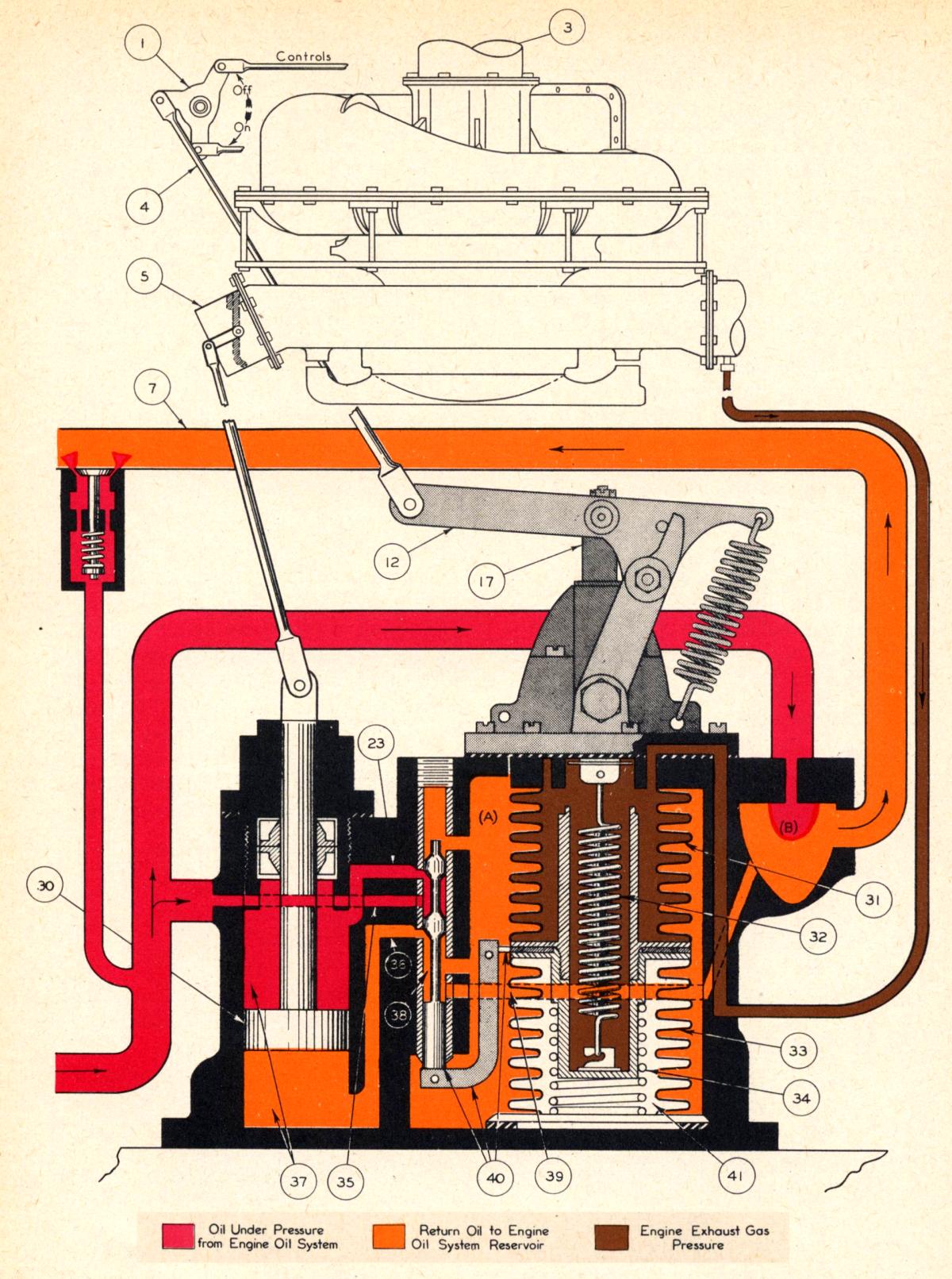
Turbosupercharger Regulator Operation — Lockout Position (Fig. 8)
When the turbosupercharger control lever on the pilots' pedestal were placed in the OFF position, the cables caused bell crank (1) to rotate counterclockwise and move regulator tension shifter lever (12) into the mechanical lockout position.
When the tension shifter lever (12) was in the lockout position, stop washer (25) on the tension shifter rod (17) was against its stop on sleeve (29). This held the valve rod assembly (40) in the full OFF position. Therefore, spring (32) had no tendency to move the valve rod center plate position. In the Lockout position, engine oil under pressure passed through passage (35), valve sleeve (38), and passage (36) into cylinder (37) below piston (30), and forced the piston to the cylinder top, thereby fully opening waste gate (5). With the waste gate open the exhaust gas escaped through the waste gate and developed no turbosupercharger nozzle box pressure in the to drive the turbine wheel. As oil pressure forced piston (30) toward the cylinder top oil in the cylinder above the piston was bled back into the oil reservoir through port (23), valve sleeve (38), and through port (20) into chamber (A). The oil passed from chamber (A) through port (20a), valve sleeve (38), and passage (39), to the oil return chamber (B), and from there back to the engine oil reservoir through line (7).
Chamber (A) remained full of oil at all times, which served to dampen any tendency of the bellows and center plate assembly (40) to flutter or vibrate.
The function of the oil jet (27) was to bleed enough hot oil through the lines to prevent congealing when the airplane is being operated in low temperatures.
Pressure relief valve (10) provided a passage back to the reservoir for the surplus oil that was not used in regulator operation and could not return through oil jet (27). The valve tended to maintain a constant oil pressure in the line (15).
While the turbosupercharger regulator control is in the OFF position, engine throttle valve position has no effect on the operation of the turbosupercharger.
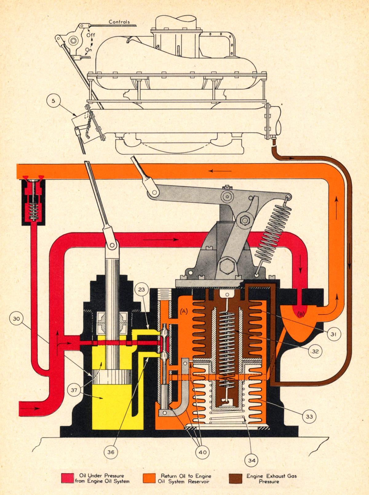
Turbosupercharger Regulator Operation — On Position (Fig. 9)
 |
| Fig. 9. Turbosupercharger Regulator — ON Position |
When the turbosupercharger control lever was placed in the ON position, cable movement caused bell crank assembly (1) to rotate clockwise. Bell crank (1) rotation moved the regulator tension shifter rod lever (12) by means of link (4) to the ON position. This raised the tension shifter rod (17) and through spring (32), the center plate and valve rod assembly (40) against the pull of the scaled vacuum bellows (33) to the position shown in Figure 9. This allowed pressurized engine oil to enter passage (35), pass through valve sleeve (38), and through passage (23) into the cylinder (37) above the piston. Oil pressure moved piston (30) downward, and the oil in the lower part of the cylinder (37) bled back to the oil reservoir through passage (36), valve sleeve (38), passage (39), and the oil return line (7).
When the regulator operating mechanism was in the ON position the tension of springs (32) and (34) was balanced against the force exerted by the pressure difference between the partial vacuum in bellows (33) and exhaust pressure in bellows (31). The force direction of the two springs is up toward the ON position, and the force of the two bellows is down toward the OFF position.
When engine speed was increased, exhaust gas pressure in the bellows (31) also increased, upsetting the balanced forces that held the center plate and valve rod assembly (40) stationary. The center plate and valve rod assembly (40) then moved toward the OFF position, opening the exhaust waste gate (5) enough to reduce the exhaust and bellows pressure(31) and cause valve rod assembly (40) to move to its HOLDING position, described below. This closed both the passages (23) and (36), locking the oil in cylinder (37) on each side of piston (30) and holding waste gate (5) fixed until one or both of the following things occur:
1. The pilot changed the control lever position, which would change the force being exerted by spring (32).
2. The engine speed was increased or is decreased enough to change the exhaust gas pressure in bellows (31).
Any degree of engine manifold pressure, from no boost to full boost, could be obtained by placing the pilot's turbosupercharger control lever in the desired position. The control linkage movement between the pedestal and the regulator increased or decreased the tension on spring (32). When the tension on spring (32) decreased it allowed the center plate and valve rod assembly (40) to move toward the OFF position, allowing oil from the engine pressure line (15) to enter the valve sleeve (38) and through passage (36), force piston (30) toward the top of the cylinder. This would open waste gate (5) through link (11). The upward travel of piston (30) forced the oil above the piston in the cylinder (37) to the engine oil reservoir through the passage (23), the valve sleeve (38), through the passage (20), into the regulator body chamber (A). The oil is then forced through the passage (20a), into valve sleeve (38), out through passage (39), into return chamber (B), and then through line (7) to the reservoir.
Turbosupercharger Regulator Operation, HOLDING Position (Fig. 10)
 |
| Fig. 10. Turbosupercharger Regulator — HOLDING Position |
When the waste gate opened exhaust pressure in the tail pipe and bellows (31) decreased. The decreased pressure in the bellows (31) allowed springs (32) and (34) to move the valve rod assembly to the oil position until the exhaust waste gate (5) closed enough to cause the exhaust gas pressure in the bellows (31) to move valve rod assembly (40) to the HOLDING position. In this condition both passages (23) and (36) were closed by the valve rod preventing further waste gate movement until the forces that held the center plate and valve rod assembly (40) in equilibrium were again upset.
When the pilot's control lever is moved toward the ON position, the increased tension on spring (32) moves the valve rod assembly (40) to the ON position and closed the exhaust waste gate (5).
When the exhaust waste gate is closed, additional pressure in the tail pipe caused the turbosupercharger speed to increase until the additional exhaust gas pressure in the tail pipe acts on bellows (31) and causes the valve rod assembly to move to the HOLDING position.
The Trouble with the Eclipse Regulator
While the Eclipse regulator could maintain a desired level of boost under ideal conditions, the actual environment in which it operated was seldom ideal. Pilots were ultimately interested in maintaining a certain manifold pressure, but by measuring exhaust pressure, the regulator only had an indirect indication of manifold pressure. Any change in altitude, airspeed, air density, air temperature, engine mixture strength, engine rpm, intercooler shutter position, alternate air selection, control rigging and myriad other things could affect the actual manifold pressure being delivered by the turbosupercharger. This meant the pilots had to constantly fiddle with the turbosupercharger controls in order to maintain desired manifold pressure. Additionally, the Eclipse regulator did not prevent a ham-handed flight crew from overspeeding the turbine wheel. A better scheme was needed – one that sensed carburetor inlet pressure directly and controlled the turbosupercharger electronically.
On to Part 2: The Minneapolis-Honeywell Electronic Control System
Send mail to
![]() with questions or comments about this web site.
with questions or comments about this web site.
![]()