Turbosupercharger Control Systems
Part 2: The Minneapolis-Honeywell Electronic Control System
Compiled by Kimble D. McCutcheon
Published 1 Oct 2020
Introduction
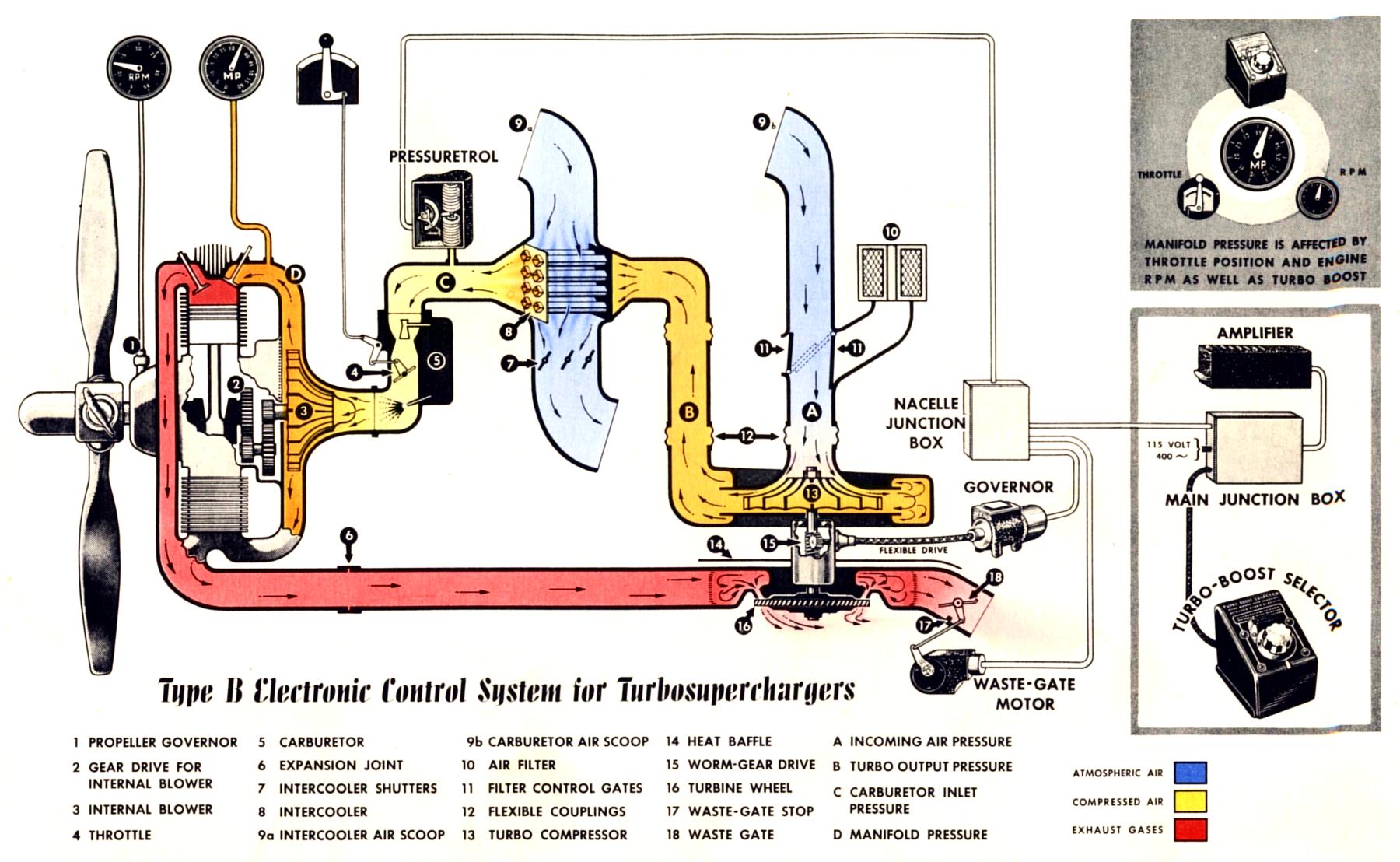
Figures 11 and 12 illustrate the Minneapolis-Honeywell (M-H) turbosupercharger control system layout. The main cockpit components were the turbo-boost selector, main junction box and amplifier(s). In the engine nacelles were nacelle junction boxes, Pressuretrols, turbo governors, and waste-gate motors. Each of these components is discussed below.
|
| Fig. 11. Turbosupercharger Installation Schematic, Minneapolis-Honeywell Control System |
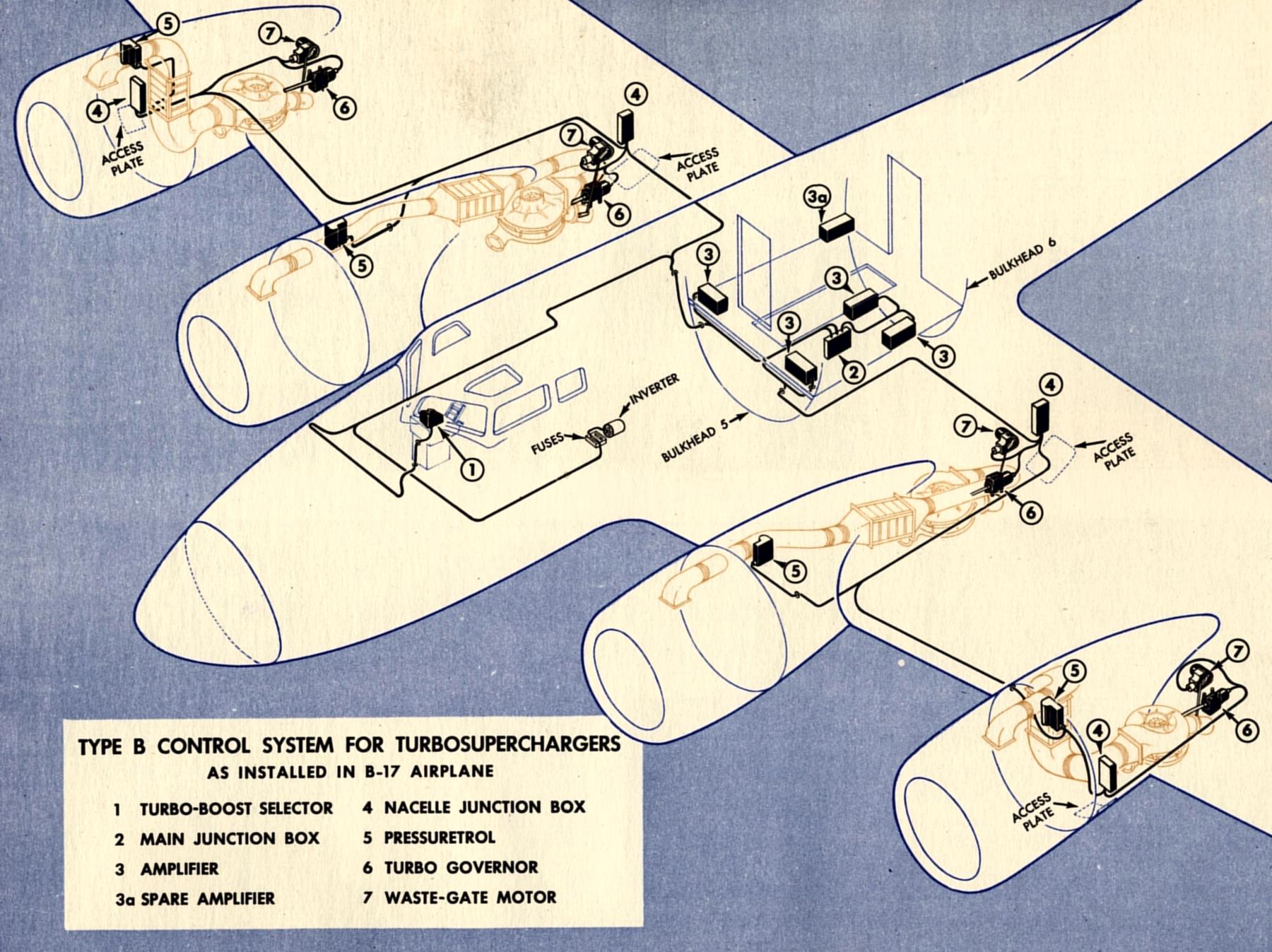 |
| Fig. 12. Electronic Turbosupercharger Control System |
Turbo-Boost Selector
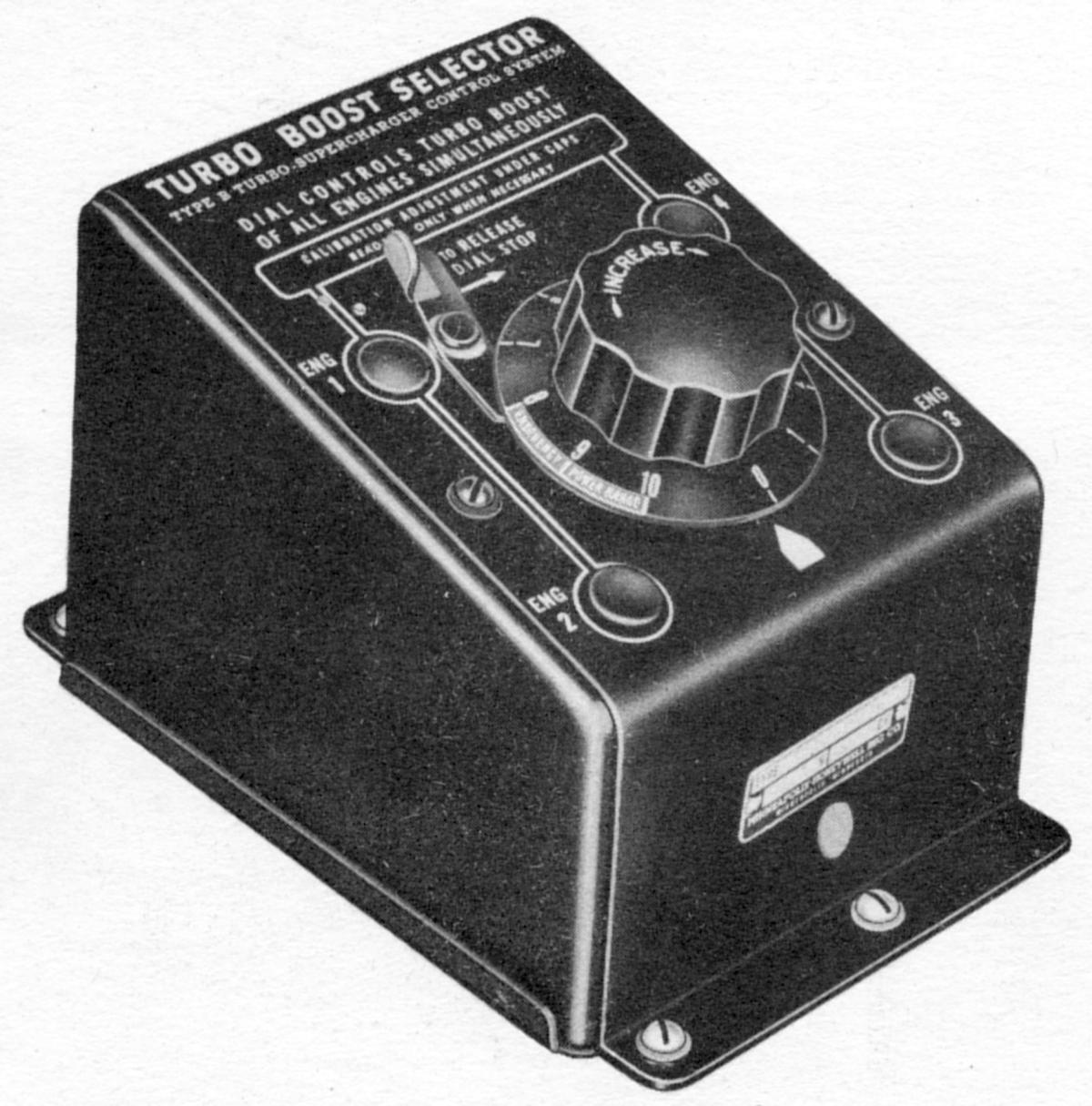
The turbo-boost selector (Fig. 13) was the manual control unit of the system. It was used by the pilot or copilot to select the carburetor inlet pressure necessary to produce the desired manifold pressure for any flight condition. On multi-engine airplanes, the turbo-boost selector also provided a means of synchronizing manifold pressures of all engines. This was accomplished by adjustment of calibrator potentiometers, one potentiometer in the control circuit for each engine.
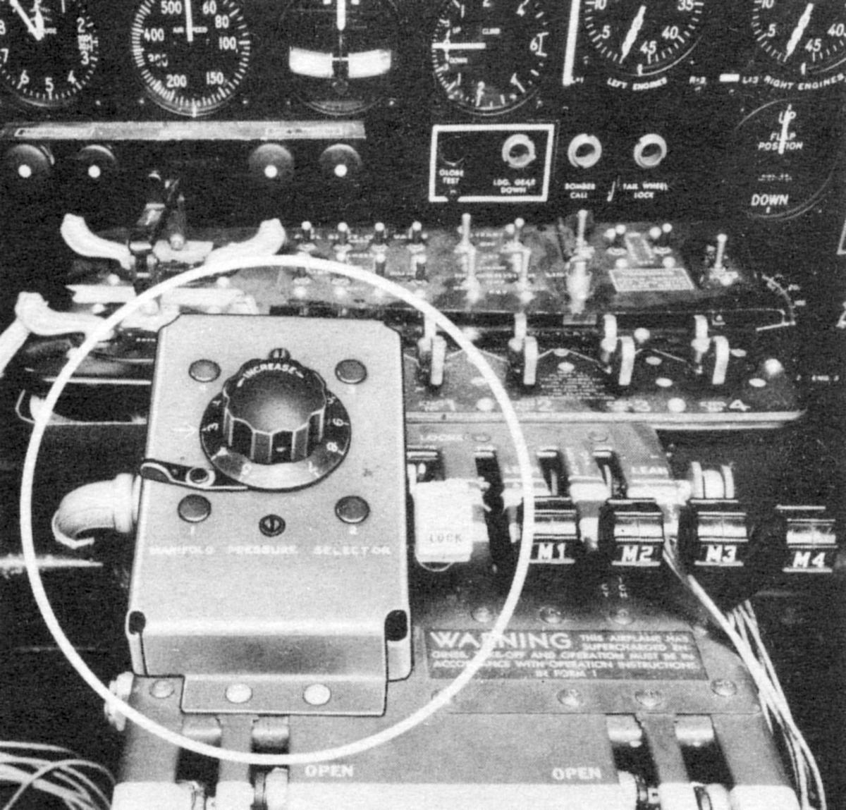
The turbo-boost selector was a rectangular aluminum box with slanting top and a dull black finish. Some installations were custom. Boeing provided its own enclosure in the B-17 (Fig. 14) and mounted it inside the control pedestal in the Boeing B-29. Carburetor inlet pressure, and therefore manifold pressure, was set by turning the control knob. Turning the knob clockwise called for a closed waste gate, which increased manifold pressure.
 |
 |
| Fig. 13. Turbo-Boost Selector | Fig. 14. Turbo-Boost Selector in Boeing B-17 |
The dial was graduated from "1" to "10," with a reference arrow below the dial. These graduations were used for relative position only, and did not refer to absolute pressure values. In practice, "8" was usually calibrated for maximum take-off power. A latch that stopped the dial at "8" had to be released before the dial could be turned beyond that point. The latch slid lengthwise slightly on its pivot, so it will drop above the dial-stop notch when it was tripped. Therefore, the latch did not have to be held when the dial was turned beyond "8," allowing the unit to be operated with one hand.
Since the range above "8," represented by "9" and "10," provided manifold pressures in excess of the mean effective pressure for which the engine was designed, this range was not used except in emergencies. It was "red-lined" and marked "EMERGENCY POWER RANGE." Four snap plugs covered the internal calibration potentiometers. An AN-connector receptacle was mounted on the bottom of the unit from the inside.
 |
 |
| Fig. 15. Turbo-Boost Selector Cutaway | Fig. 16. Turbo-Boost Selector Internal Wiring |
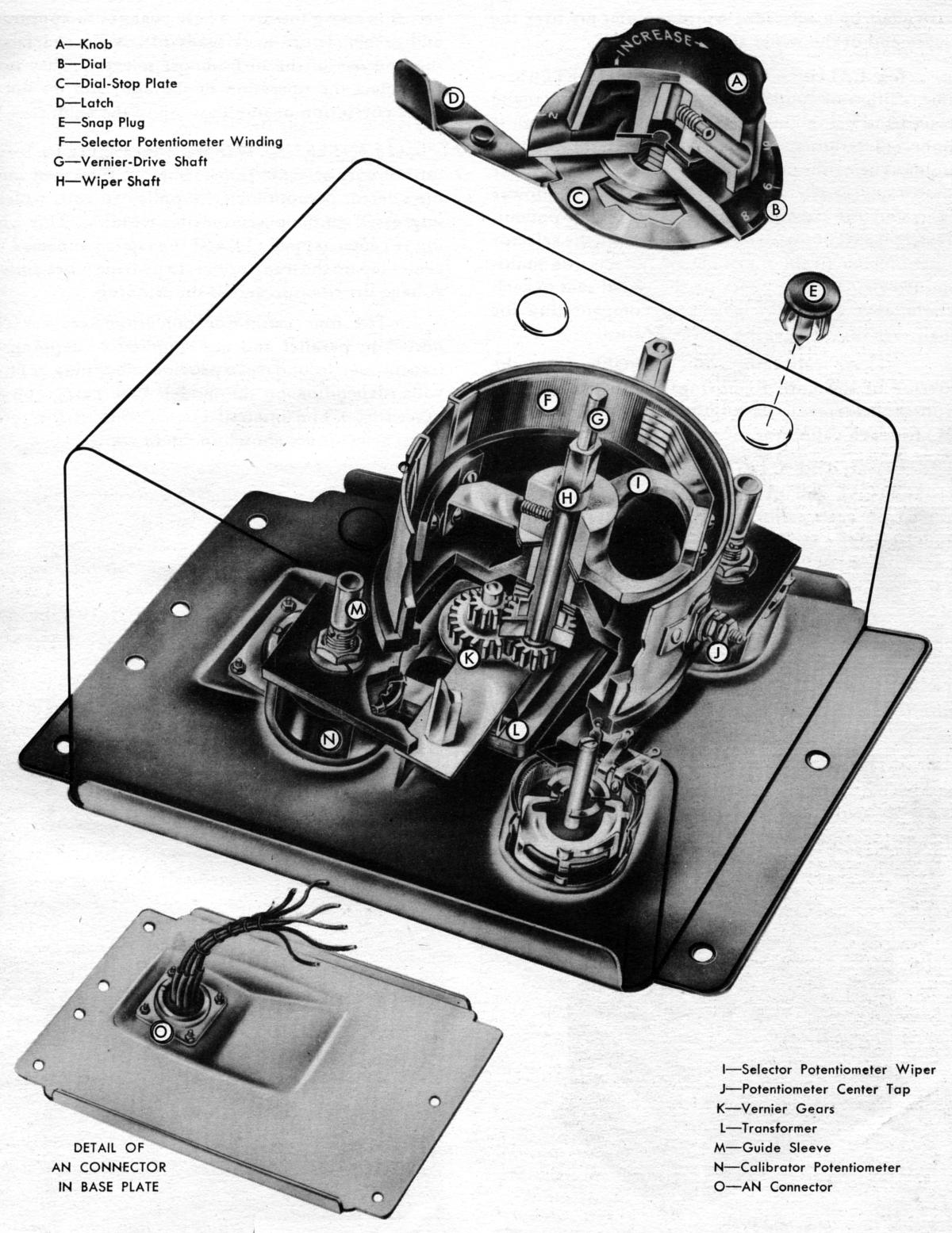
The selector potentiometer assembly (Fig. 15) consisted of a large cylindrical winding (F) and a wiper (I) that contacted the winding inner surface. The wiper was mounted on the wiper shaft (H), which was turned by the knob through the vernier drive shaft (G) and gears (K) at approximately 1:3 ratio. The knob was fastened to the vernier drive shaft by a setscrew, while the dial fitted over the wiper shaft square end. Four calibrator potentiometers (N) were arranged around and below the selector potentiometer. Each was connected to the control system for the corresponding engine. The calibrator for engine No. 1 was at the upper left, for engine No. 2 at lower left, for No. 3 at lower right, and for No. 4 at upper right. These potentiometers transmitted the electrical signal from the selector potentiometer to the four control systems on multi-engine airplanes. By varying the signal sent to each system, they provided a means of compensating for small variations in engine characteristics. These calibrators were adjustable from the exterior of the unit. Removing the snap plugs (E) exposed the screwdriver adjustment and guide sleeve (M) for each calibrator.
When turbo-boost selector units were factory installed in a special case, as in B-17 airplanes, or without cases, as in B-29 airplanes, the reference arrow might be found in a different location with respect to the front of the unit. The calibrator adjustment for each engine was then be found in a correspondingly different position.
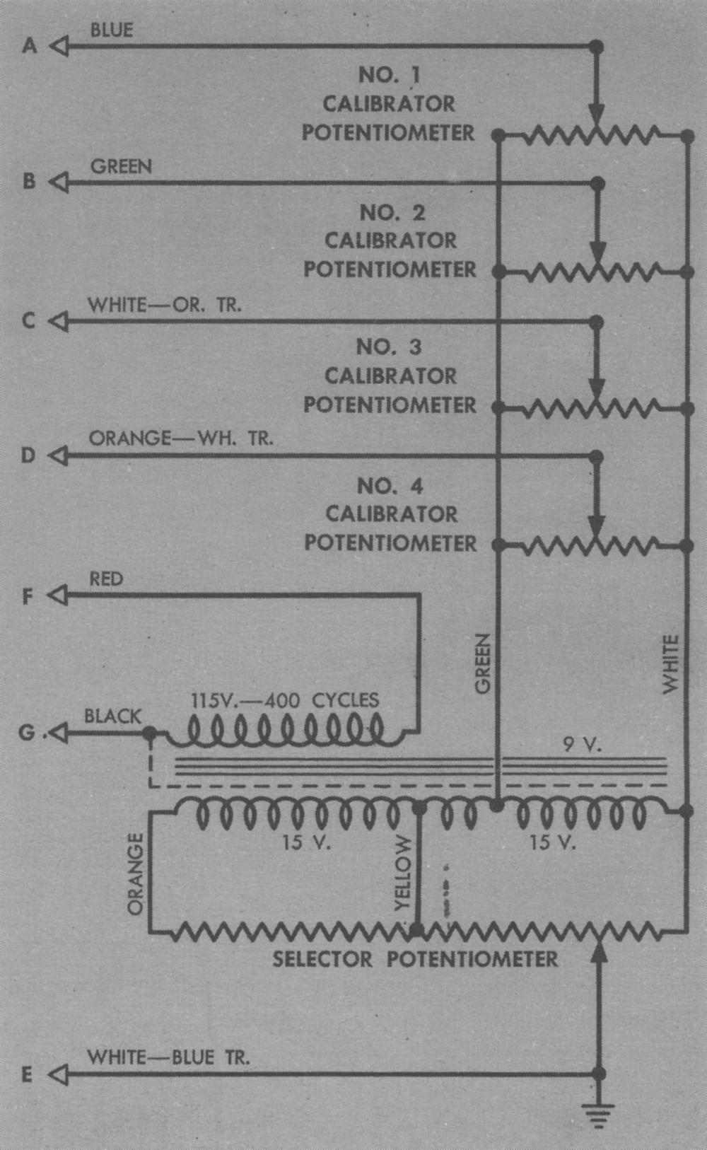
The turbo-boost selector transformer (L), located under the selector potentiometer, supplied 30 VAC, which was impressed on the potentiometer winding. This winding was center-tapped (J), and the tap was connected to a center tap on the transformer, to provide more uniform voltage distribution across the winding. The four calibrator potentiometers were connected in parallel and were supplied by tapping the transformer secondary to provide either 9 or 15 VAC, depending on the model. Internal turbo-boost selector connections are depicted in Figure 16.
Pressuretrol
Actuated by manifold pressure variations at the carburetor intake, the induction-system Pressuretrol was the primary sensing device of the turbosupercharger control system. Mounted on a bracket near and connected to the induction system by a short 1/8" hose, it was actuated by pressure variations at the carburetor inlet. It consisted of a voltage-dividing potentiometer operated by a pair of bellows connected to the induction system.
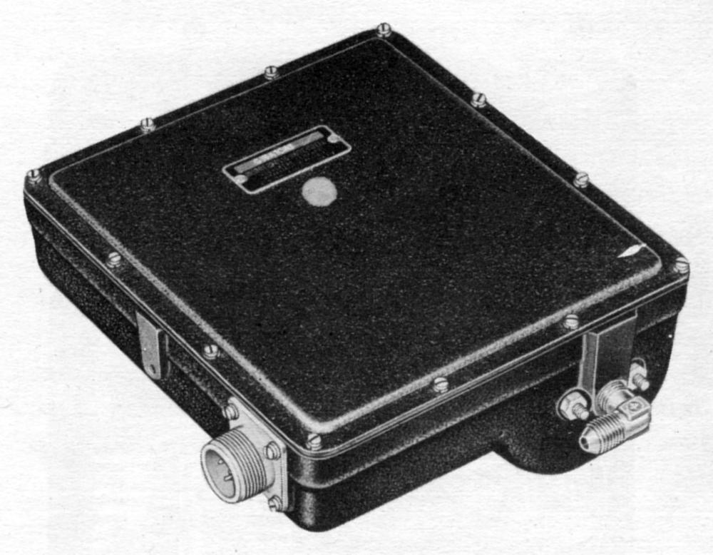
The Pressuretrol was housed in a cast aluminum case, with a flat cover of the same material held on by 12 cover screws. Both case and cover had a black crackle finish. Three tapped mounting holes in the casting sides provided for attaching the Pressuretrol to its mounting brackets. The unit was connected to the pressure source through a 90° brass elbow screwed into the bottom of the case. A small hole at the bottom of the case permitted drainage and ventilation. Electrical connections to the unit were made through a three-prong AN-connector receptacle at the case side. Two adjusting screws at the top provided pressure range adjustment.
 |
 |
 |
| Fig. 17. Pressuretrol Exterior | Fig. 18. Pressuretrol Interior | Fig. 19. Pressuretrol Schematic |
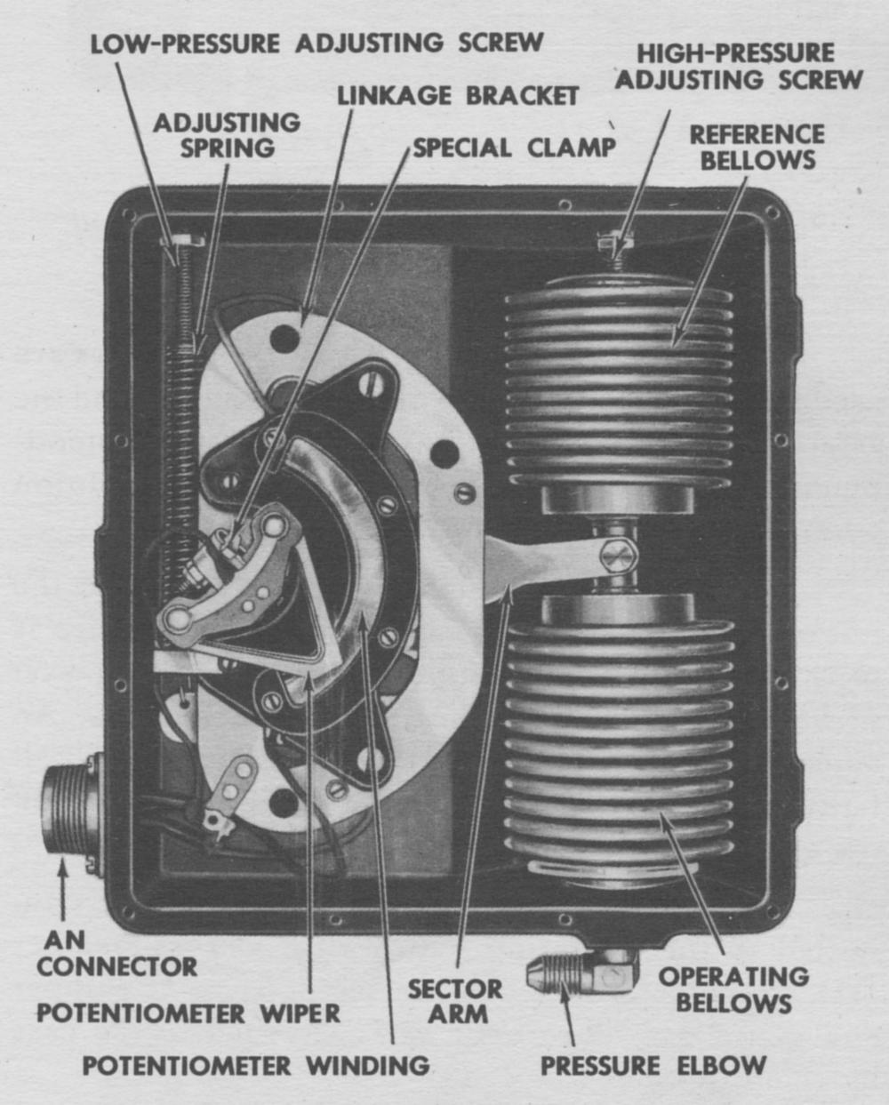
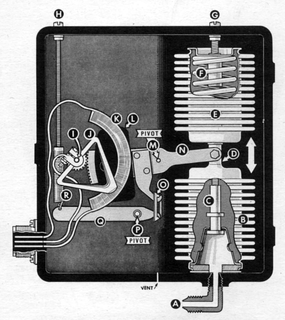
Two bellows, an operating bellows and a reference bellows, were used in the Pressuretrol. Together they moved the potentiometer wiper by means of the sector arm and pinion gear (Fig. 19).
The operating bellows (B) was bolted to the bottom of the case, and carburetor-inlet pressure was piped to its interior through the elbow (A). A gasket prevented leakage at the bellows bottom. An adjustable internal stop (C) prevented excessive collapse or expansion, which would have driven the wiper off the potentiometer winding end. The reference bellows (E) was rigidly connected to the operating bellows by a cross-member (D), to which was attached the sector arm. The upper end of the reference bellows was attached to the case by an adjustment screw (G).
The reference bellows enabled the Pressuretrol to maintain desired absolute pressures under varying atmospheric temperature and pressure conditions. It had the same cross-sectional area as the operating bellows, and therefore atmospheric pressure changes affected both equally. Since the operating bellows and reference bellows were arranged to oppose each other, atmospheric pressure change was canceled out.
To eliminate interior pressure variations due to temperature changes, air was evacuated from the reference bellows. An internal compression spring (F), which was not appreciably affected by temperature changes, took the place of internal air pressure to prevent collapse.
 |
 |
| Fig. 20. Pressuretrol Bellows Showing Forces Acting on Bellows | Fig. 21. Pressuretrol Schematic |
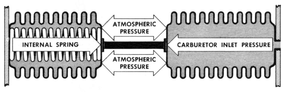
The balance of forces acting on the two bellows was shown in Figure 20. Two forces were impressed on the operating bellows — internal pressure, which was carburetor inlet pressure, and external or atmospheric pressure. The two forces operating on the reference bellows were the internal spring compression and atmospheric pressure. Since the bellows opposed each other, atmospheric pressure cancels out. Therefore, it may be seen that carburetor inlet pressure was constantly opposed only by the spring tension. (An adjusting spring, R, was added for calibration purposes only. This allowed pressure control in terms of absolute pressure, regardless of altitude or climate.
The sector arm (N) translated the straight line bellows assembly motion into a rotary motion that moved the wiper across the potentiometer winding. The sector arm turned on a pivot (M) that was held by the linkage bracket (not shown). One end pivoted on the bellows cross-member (D), and the other end had a gear sector cut into it that meshed with a pinion on the potentiometer wiper shaft (I). The laminated steel counterbalance (L) prevented erratic sector arm movement due to the airplane vibration. The sector arm was connected to the adjusting spring (R) by means of the adjusting spring link (O).
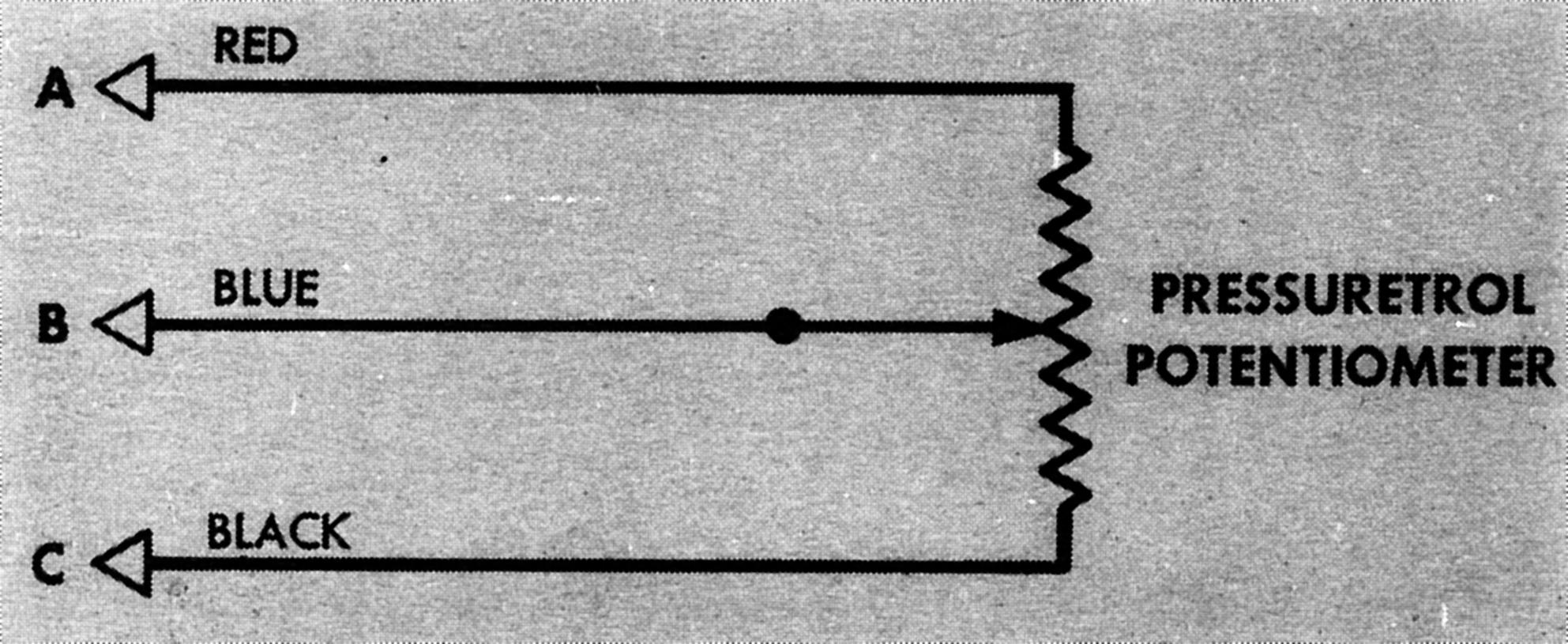
The Pressuretrol potentiometer (K) was part of the electrical control circuit. Potentiometer wiper movement produced a signal calling for proper movement of the waste gate, depending on whether carburetor inlet pressure increased or decreased. The potentiometer resistance was 800 ohms (+20%, -8%) and voltage across potentiometer was 30 VAC. Wiper tension was 7.0 to 12.5 grams (Fig. 21).
As it was installed in the unit, the upper end of the potentiometer winding was the "low-pressure" end. When carburetor air pressure dropped, the operating bellows collapsed and the potentiometer wiper (J) was moved by the sector arm and gears toward the top of the potentiometer winding, producing an electrical signal which calls for a closed waste gate. When pressure increased, the opposite was true. The potentiometer was calibrated for a maximum pressure variation of 16 to 34 inHgA. Voltage across the potentiometer was supplied by one secondary of a transformer located in the nacelle junction box. The potentiometer winding was fastened to the linkage bracket by four screws. The wiper was attached on the wiper shaft (I) by a double clamp held tight by a special bolt and locking nut. An anti-backlash spring around the shaft took up play in the linkage so the wiper always operated directly against the pressure of the operating bellows. It also acted as a safety feature to drive the wiper to the bottom of the potentiometer winding in case the sector gear and pinion become disengaged.
Two calibration adjustment screws at the case top were provided for adjusting the pressure range through which the Pressuretrol operated. These were painted red and marked "CALIBRATION SCREWS-DO NOT TAMPER," and were not be adjusted in the field. The high-pressure adjustment screw (G) raised or lowered the reference bellows top to vary the reference pressure against which the operating bellows must act. This had the effect of establishing the pressure required to move the wiper to the high-pressure end of the winding. The low-pressure adjustment screw (H) varied the adjusting spring (R) tension against which the sector arm and wiper mechanism must act as the operating bellows contracted because of a decrease in carburetor inlet pressure. Thus, adjustment screw (H) regulated the amount of pressure drop required to move the wiper to the low-pressure end of its winding. The tension of the adjusting spring was transmitted to the sector arm through the adjusting spring lever (Q) and link (0). The adjusting spring lever turned around pivot (P). The sector arm travel limits could varied up or down by the adjustable internal stop (C) in the operating bellows. This adjustment, as well as the calibration adjustments, was set at the factory and was not to be changed in the field.
Turbo Governor
The turbo governor (Fig. 22) consisted of two separate mechanisms, each of which performed a safety control function. The accelerometer prevented manifold pressure overshooting during sudden pressure increases, yet allowed very rapid turbosupercharger acceleration. The overspeed mechanism automatically limited the turbosupercharger turbine wheel to a safe top speed. Both mechanisms were operated by a single shaft in the governor, which was driven by a flexible drive from the turbosupercharger tachometer connection. The turbo governor was driven at a speed proportional to the speed of the turbosupercharger by a gear reduction in the turbo, which was different in different types of turbosuperchargers.
 |
| Fig. 22. Turbo Governor Cutaway |
Turbo Governor Accelerometer Section
The governor accelerometer section (Fig. 24), located under the cup-shaped accelerometer cover, was operated by the inertia rotor, located in the governor housing. This heavy rotor was free to turn on the rotor shaft, but was coupled to the shaft through a torque spring. When the shaft was rotating at a uniform rate, the rotor also rotated at the same rate in a fixed position with respect to the shaft. However, when the shaft accelerated, the rotor inertia caused it to lag behind the shaft, flexing the torque spring. The rotor lag was translated into straight-line motion by a cam-and-roller mechanism that moved the wiper across the potentiometer winding and produced an electrical signal opposed to the signal that produced the acceleration. The accelerometer signal tended to open the waste gate slightly as manifold pressure approaches the value called for. This prevented overshooting manifold pressure, yet allowed rapid turbosupercharger acceleration. As acceleration was reduced, the torque spring brought the rotor hack to its original position with respect to the shaft, and the wiper was returned to its rest position.
The cam-and-roller mechanism consisted of a cylindrical cam plate with inclines cut into it, and a cam-roller assembly containing rollers that rode on the inclines or cam surfaces. (For purposes of illustration, Figure 24 shows only two rollers and inclines; the actual unit had three.) The cam plate was held rigidly on the rotor by a locking plate. The cam-roller assembly was keyed to the rotor shaft by means of the push-rod actuating crosshead and the cam-roller-assembly guide, which prevented the roller assembly from turning on the shaft, but allowed it to slide freely along the slotted portion of the shaft.
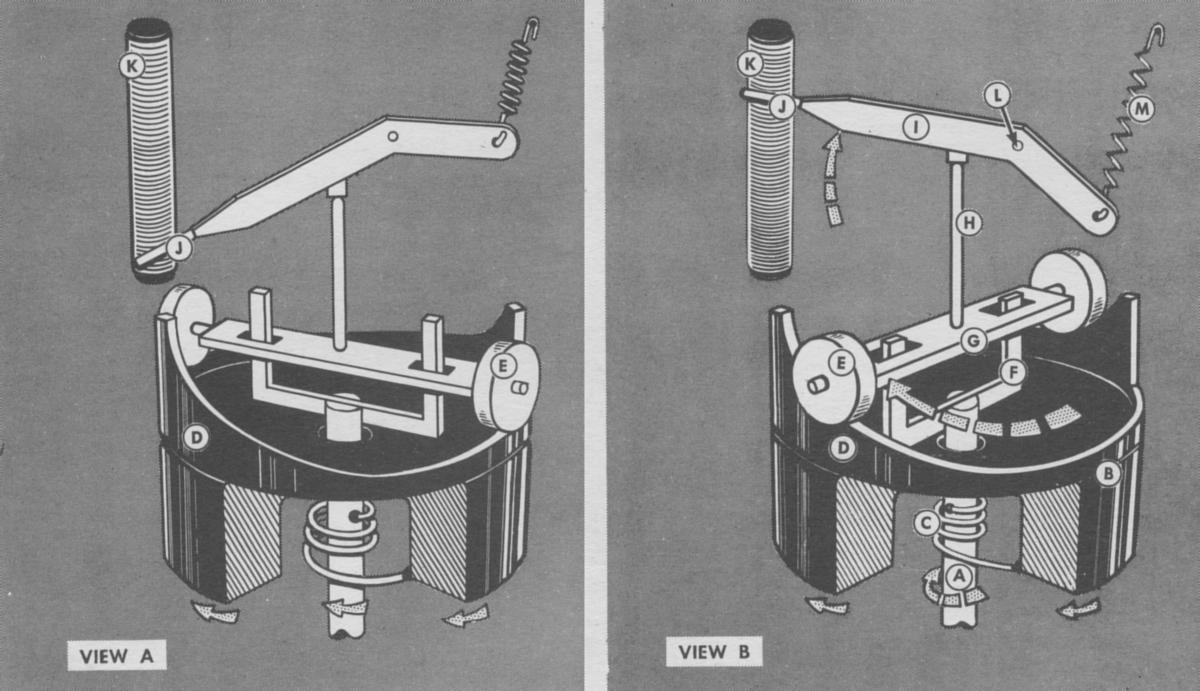 |
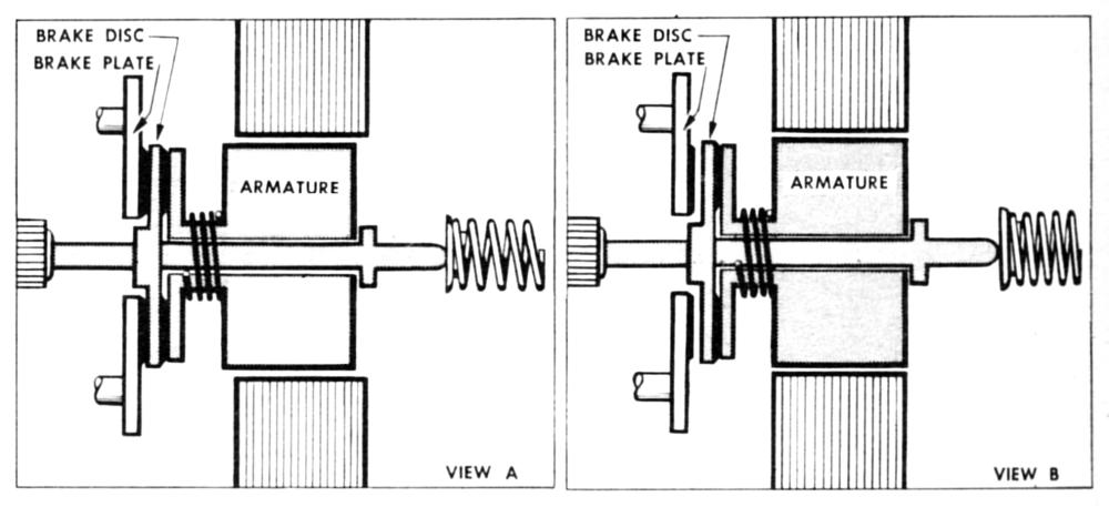
| Fig. 24. Turbo Governor Accelerometer Operation. View A = Normal Position; View B = Excessive Acceleration. (A) Governor Shaft; (B) Inertia Rotor; (C) Torque Spring; (D) Cam Plate; (E) Cam Roller; (F) Guide; (G) Crosshead; (H) Push Rod; (I) Wiper Arm; (J) Potentiometer Wiper; (K) Potentiometer Winding; (L) Wiper Arm Pivot; (M) Return Spring. |
The rotor shaft was hollow above its slotted portion and contained a double-pointed push rod that seated in a depression in the push-rod-actuating crosshead. When the crosshead moved along the shaft, the push rod was also moved. The other end of the push rod seated in a potentiometer-wiper-actuating crosshead that slid in slots in the frame assembly.
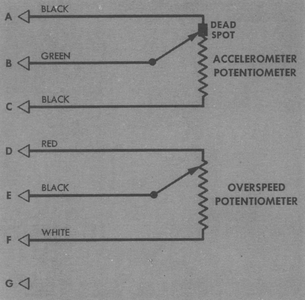
The potentiometer-wiper arm rested on the wiper-actuating crosshead, and was pivoted in the frame assembly. The potentiometer wiper was made with two contact fingers that contacted the potentiometer winding on opposite sides. This double contact minimized the possibility of aircraft vibration breaking contact between the wiper and the winding. A large fiber washer on each end of the winding prevented the wiper from moving beyond it. A small electrical dead spot, formed by soldering several turns together, was provided at the end of the winding nearest the bearing plate. Its purpose was to prevent minute wiper fluctuations from affecting system operation. A terminal block located on the frame assembly provided a connection for wiring from the governor overspeed section. The seven-prong AN-connector receptacle was mounted permanently on the frame assembly.
In operation, the cam rollers (F) normally rested on the flat portions of the inclines cut into the cam plate (D). (See view A.) The potentiometer wiper (J) rested at the bottom of its winding (K), and no electrical signal was sent by this portion of the governor. When acceleration occurred (view B), the rotor (B) lagged momentarily behind rotation of the shaft (A), and the cam surfaces were turned with respect to the rollers. The rollers were forced to ride along the cam surfaces and up the inclined sections of the surfaces. This moved the roller assembly and crosshead (G) along the shaft, displacing the push rod (H). The push rod acted on the wiper arm (I), moving the wiper across its winding. This produced a signal calling for the waste gate to open slightly and prevent overshooting of manifold pressure. When the rotor shaft was no longer accelerating, the cam rollers moved down their inclines to their normal positions, and the wiper was returned to the bottom of the winding by the wiper-arm return spring The rest position of the wiper could be changed by a fulcrum adjustment that moves the wiper-arm pivot.
Turbo Governor Overspeed Section
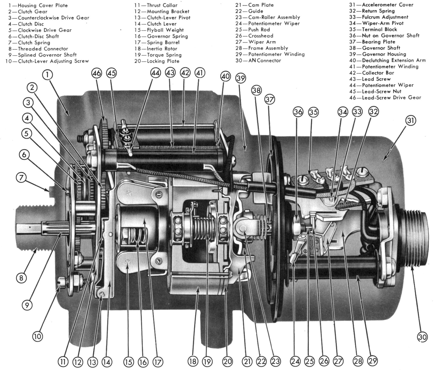
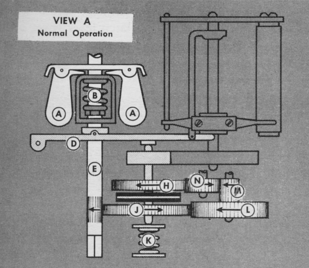
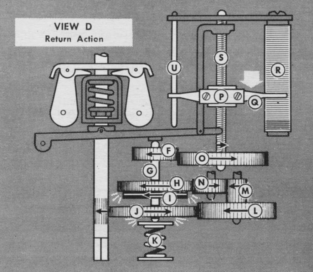
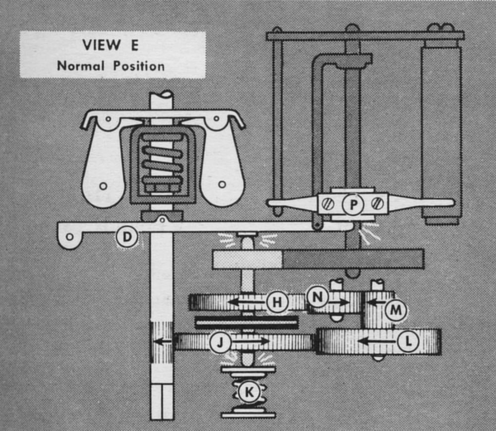
The governor overspeed section (Figs. 25 – 29) was located within the governor housing, under the housing cover plate. Its operating parts consisted of a gear train, a flyball governor, a clutch, and a driving mechanism that moved the potentiometer wiper. The gear train and flyball governor were constantly driven by the rotor shaft. The double potentiometer wiper (Q) was mounted on the threaded lead-screw nut (P), which was moved by the lead screw (5). The cylindrical potentiometer winding was contacted by the two wipers, one on each side. A collector rod on the opposite side of the assembly was also contacted by two collector wipers.
In normal speed operation (View A)-The turbo-governor shaft (E) drove the gear train consisting of gears J, L, M, N, and H, as well as the flyball governor, made up of the two flyball weights (A). All these parts rotated constantly when the governor shaft was rotated. Note that all these gears rotated freely on their shafts, and gears H and J rotate in opposite directions. Between the two gears was a clutch disc (I) that was rigidly attached to the clutch-disc shaft (G). The clutch lever (D) bore against the top of the shaft, and the clutch spring (K) bore against the bottom end of the shaft. Other parts of the assembly (shaded in view A) were normally not in operation.
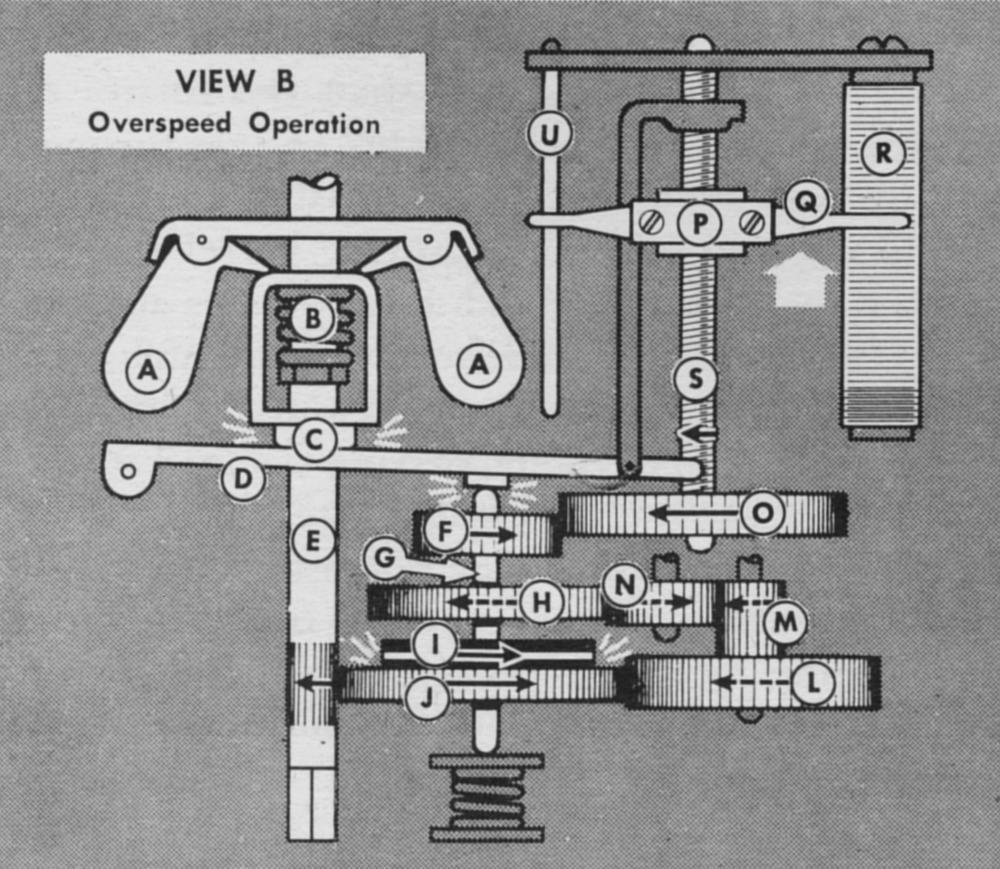
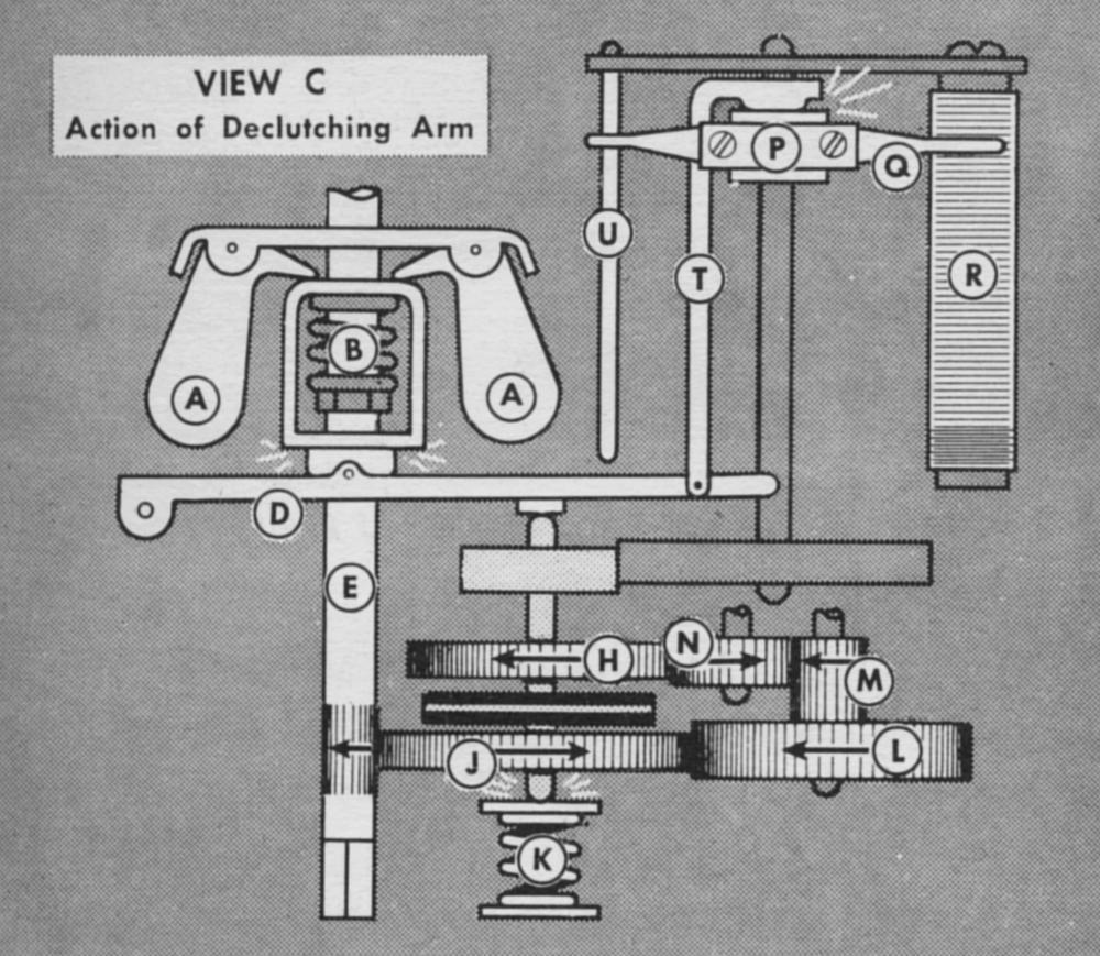
In overspeed operation (View B), the governor shaft (E) rotated at an excessive speed, causing the flyball weights (A) to be thrown outward by centrifugal force, compressing the governor spring (B) and forcing the spring barrel against the clutch lever (D). The clutch lever pressed against the end of the clutch-disc shaft, forcing the clutch disc against gear J. This caused the clutch-disc shaft and the attached gear (F) to rotate, driving the lead screw (S) by means of the lead-screw drive gear (O). Rotation of the lead screw caused the potentiometer wiper (P), threaded to the screw, to move out on the potentiometer winding (R). The resulting electrical signal caused the waste gate to open and slow down the turbosupercharger. As the turbosupercharger began to slow down, pressure of the spring barrel against the clutch lever was diminished, and the clutch spring (K) moved the clutch disc upward until it no longer engages gear J. This stopped rotation of the clutch disc, and the potentiometer wiper remained where it was on the potentiometer winding. However, if the potentiometer wiper happened to travel to the lead screw end before the turbosupercharger had slowed sufficiently to disengage the clutch, the wiper would strike the declutching extension arm (T). (View C.) The declutching extension arm (not found on all models) was connected to the clutch lever in such a way that pressure of the wiper on this arm lifted the clutch lever against the force applied by the governor. This action had the same effect as slowing down the turbosupercharger because the clutch spring will then disengage the clutch by forcing the clutch disc away from gear (J).
 |
 |
 |
 |
 |
 |
| Figs. 25 — 29, Views A — E. Overspeed Governor Operation. (A) Governor Flyweights; (B) Governor Spring; (C) Thrust Collar; (D) Clutch Lever; (E) Governor Shaft; (F) Gear; (G) Clutch-Disk Shaft; (H) Gear; (I) Clutch Disk; (J) Gear; (K) Clutch Spring; (L) Idler Gear; (M) Pinion; (N) Idler Gear; (O) Gear; (P) Lead Screw Nut; (Q) Potentiometer Wiper; (R) Potentiometer Winding; (S) Lead Screw; (T) Declutching Arm; (U) Collector Bar. | Fig. 30. Turbo Governor Schematic | |
When the turbosupercharger decelerated to a speed where the flyball governor no longer applied force to the clutch lever (View D), the clutch spring forced the clutch disc upward against gear H, which caused the clutch disc and its attached gear (F) to rotate in the opposite direction. This caused opposite rotation of the lead-screw drive gear, resulting in downward movement of the potentiometer wiper.
As the potentiometer wiper reached the bottom of the potentiometer winding (View E) it struck the clutch lever extension fingers, forcing the lever downward against the clutch-disc shaft. This action disengaged the clutch disc from gear (H) and returned the entire mechanism to its normal-speed position.
The clutch-lever adjustment screw that moved the clutch lever pivot point was set at the factory to cause the overspeed governor to come into operation at a given maximum turbosupercharger speed. It was painted red and not field adjustable.
The turbo governor internal wiring is depicted in Figure 30. Thirty volts impressed on the accelerometer potentiometer was obtained from one secondary of the nacelle junction box transformer. The accelerometer potentiometer had a resistance of 700 ohms ±20% and a wiper tension of 11 ± 2 grams. Twenty four volts impressed on the overspeed potentiometer was obtained by tapping another secondary of the same transformer. The overspeed potentiometer had a resistance of 750 ohms ± 20% and a wiper tension of 15 ± 5 grams.
A flexible drive was provided for connecting the governor to the turbosupercharger tachometer drive. This flexible connection was necessary because the governor could seldom he mounted directly in line with the tachometer drive.
The flexible drive consisted of an internal shaft within a braided housing. It was available in two lengths: a l0-inch length for B-17 and B-29 airplanes, and a 51.2-inch length for B-24 airplanes. One end contained a square socket, which fitted over the governor rotor shaft . A coupling nut screwed onto the 7/8-inch, 18-thread connector on the governor housing. The other end of the shaft fitted the turbosupercharger tachometer drive. A coupling nut held it securely. Flexible drives were shipped with a split washer on the turbosupercharger end, to keep the internal shaft from sliding out during shipment. This washer was removed and discarded at the time of installation.
Amplifier
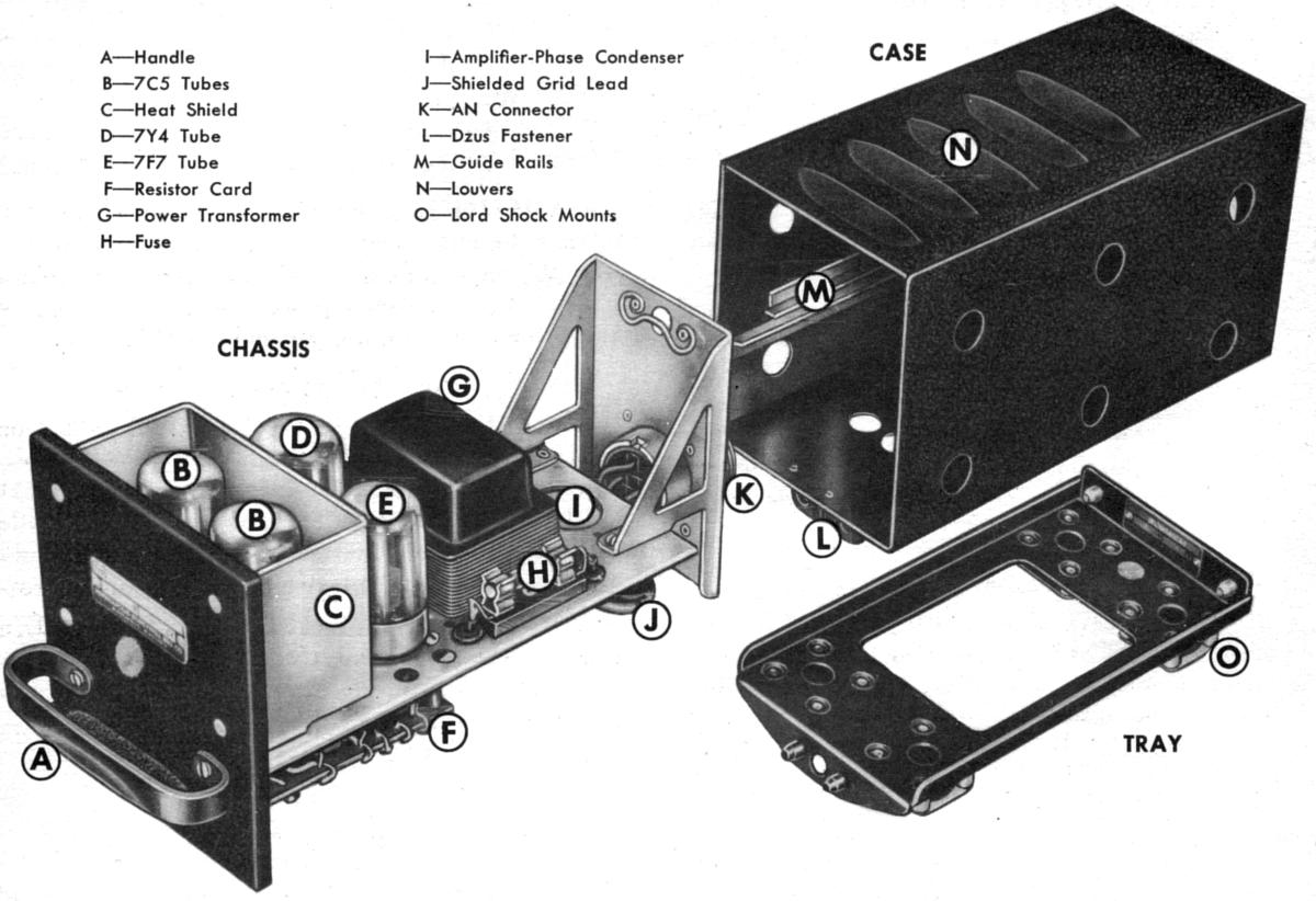
The amplifiers supplied power to operate the waste gate in response to signals received from the other system control units. There was one amplifier for each engine, plus a spare that could be rapidly replaced if one failed. The apmlifier contained a system fuse, a power transformer, resistors, condensers, and four vacuum tubes. The amplifier parts were mounted on an aluminum chassis that was housed in a rectangular case with a black crackle finish (Fig. 31). The amplifier chassis slid into the case on two horizontal guide rails (M), and was easily removed by means of a handle (A) on the front. The chassis was locked into the case by a Dzus fastener at the rear. The AN connector (K), mounted on the chassis, protruded through the rear of the case. Another Dzus fastener (L) below the front of the case locked it into the tray, which was mounted on Lord shock mounts (0). Louvers (N) on the top of the case and holes punched in the bottom and sides provided ventilation to cool the interior.
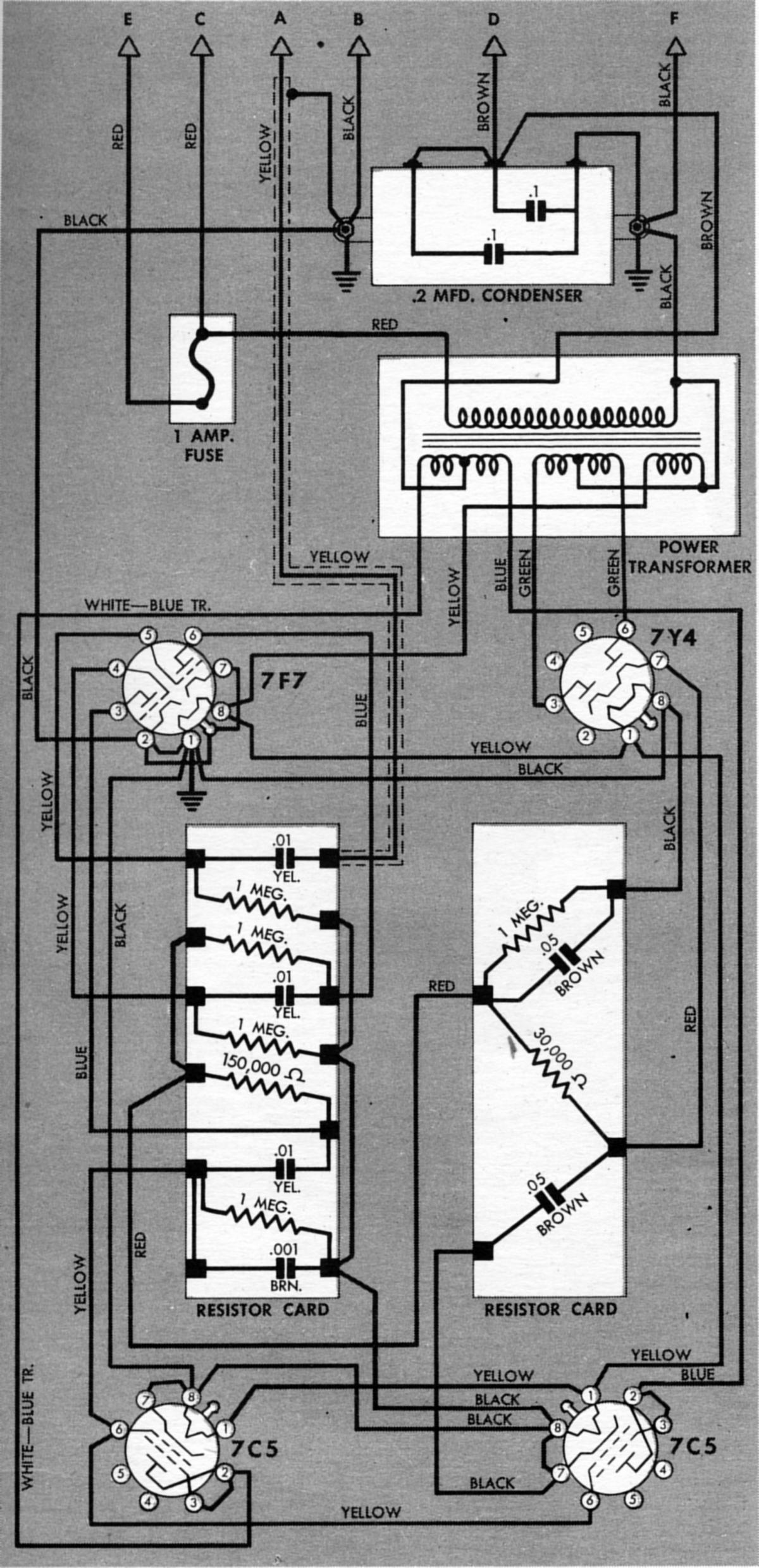
The 115 VAC supply from the airplane's rotary inverter was brought to the amplifier power transformer through a 1-ampere fuse (H) mounted on the chassis. This fuse also protected all other parts of the control system except the primary transformer winding in the turbo-boost selector. The transformer (G), also mounted on the chassis, had three secondary windings. One supplied plate current for the 7C5 tubes to energize the waste-gate motor amplifier winding. The second supplied plate current for the rectifier tube (7Y4), and the third supplied heater current for all tubes.
The amplifier was operated by four tubes ‑ one 7Y4 rectifier (D), one 7F7 duo-triode (E) used as a voltage amplifier, and two 7C5 beam power amplifiers (B) used as discriminators. The 7F7 amplified the signal from the electrical control system, while the 7C5s discriminated between a signal calling for open waste gate and one calling for closed waste gate. The 7C5 plate current operated the waste-gate motor. The 7Y4 supplies a DC plate voltage for the 7F7 tube. A heat shield (C) around the 7C5s acted as a flue to guide cooling air around them and also shield the rest of the amplifier from their heat. The 7C5s operated at a much higher temperature than the other tubes. Filter condensers and resistors were mounted on two cards (F) on the under side of the chassis beneath the tubes.
The amplifier received electrical signals from the system control units and amplified these signals to operate the waste-gate motor by energizing one of the motor windings. The motor current provided by the amplifier was either in phase with the line current or 180° out of phase. The phase of this output current, which was the same as the phase of the incoming signal, controlled the waste-gate motor rotation direction. Figure 32 depicts the internal amplifier component connections.
 |
 |
| Fig. 31. Turbosupercharger System Control Amplifier | Fig. 32. Turbosupercharger System Control Amplifier Schematic |
Waste-Gate Motor
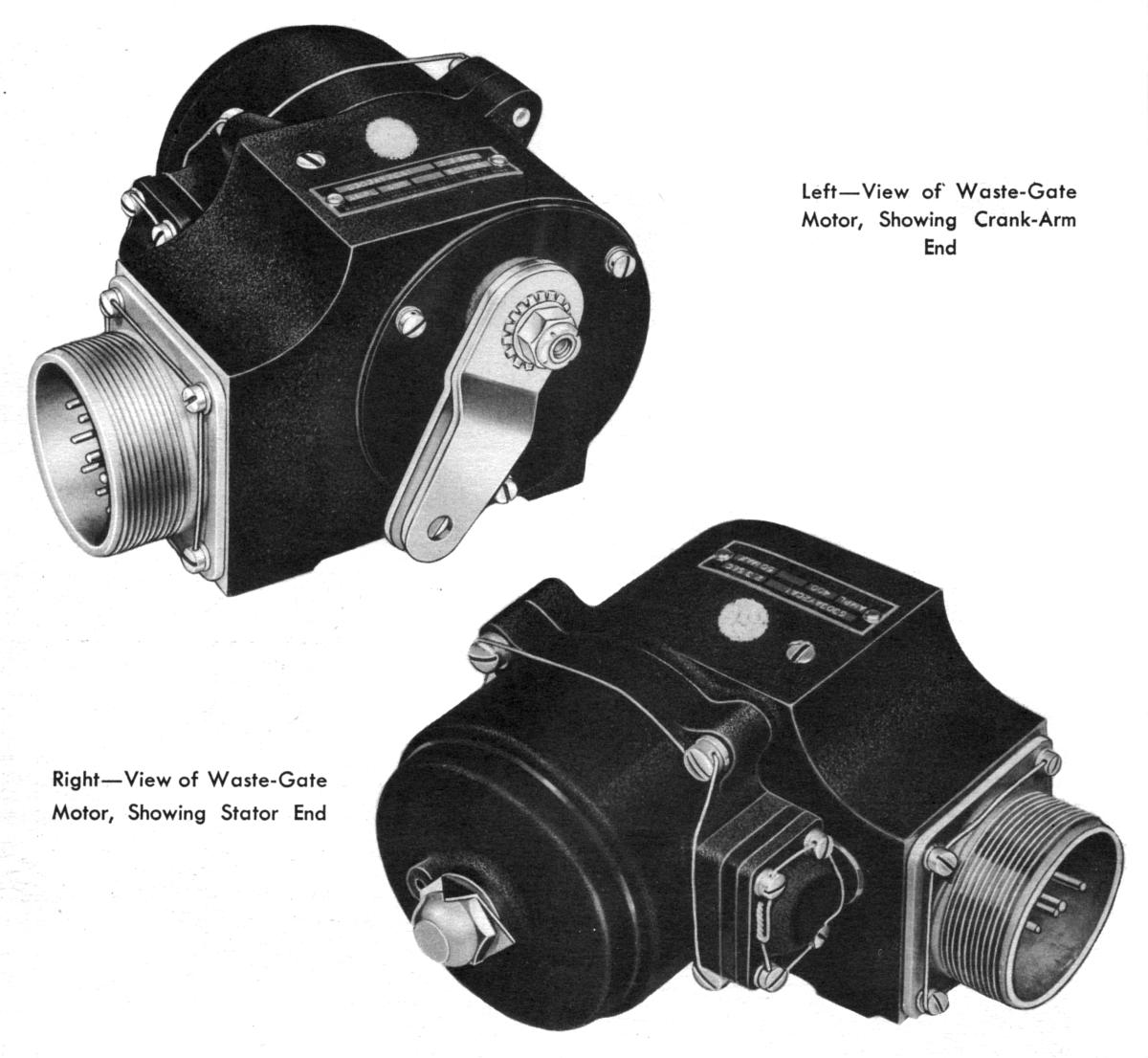
The waste-gate motor (Fig. 33) was the operating unit that moved the turbosupercharger waste gate in response to signals from the control system. It was a two-phase AC motor that transmitted power to a crank arm through a speed-reduction gear train. The crank arm was connected to the turbosupercharger waste gate by a mechanical linkage, furnished by the aircraft manufacturer.
The waste-gate motor (Fig. 34) had a black crackle finish. It was made up of a gear housing that encloses the gear train and balancing-potentiometer assembly, a cup-shaped motor housing, and an AN connector mounted on the gear housing. The housings and connector were cast aluminum. The steel crank arm was mounted externally on the gear housing, on the end opposite the stator housing.
The waste-gate motor was powered by a two-phase, reversible, induction motor contained in the stator housing. It consisted of a stator assembly and an armature assembly. The stator assembly consisted of eight pole pieces, each of which was wound with a coil of wire. The coil leads were brought into the housing through a terminal block (30), which seals the exterior against oil leakage. Alternate coils were connected in series, four coils forming the fixed or line-excited winding, and four coils forming the amplifier-excited winding. If these coils were numbered in rotation, coils 1, 3, 5, and 7 would form one winding, and coils 2, 4, 6, and 8 would form the other. Either set of coils could be used as the line-excited winding, depending on the desired direction of motor rotation. Energizing these two windings operated the waste-gate motor when movement of the waste gate was called for by the control system. The armature assembly was made up of the armature (20), the armature shaft (21), brake and clutch mechanism, and the armature assembly mounting plate (15). The armature was of laminated steel with one brass lamination at each end. It was connected to the armature shaft by means of the clutch mechanism. The armature shaft drove the gear train (13), and through it the crank arm (5), by means of a drive pinion pressed onto the end of the armature shaft.
 |
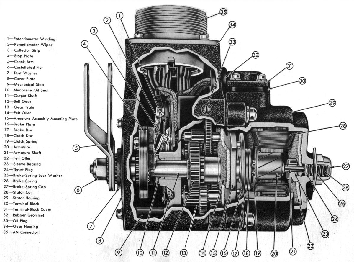 |
| Fig. 33. Turbosupercharger Waste-Gate Motor Exterior | Fig. 34. Turbosupercharger Waste-Gate Motor Cutaway |
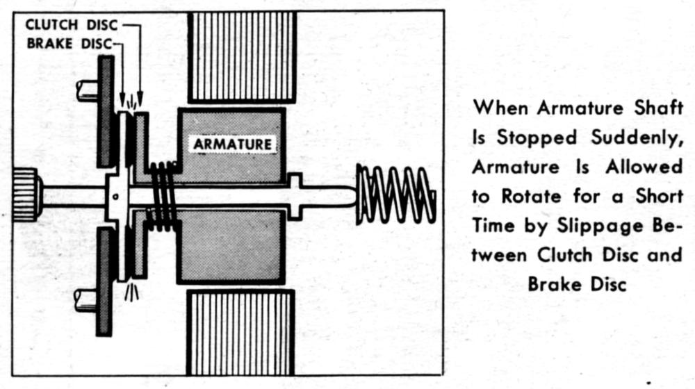
The clutch and brake mechanisms were located together at the drive end of the armature assembly. The clutch was a safety device that prevented damage to the gear train when the potentiometer wiper assembly (2 and 4) struck a mechanical stop. The brake stopped shaft rotation whenever the amplifier-phase winding ceased to be energized. The armature was not directly connected to its shaft, but drove the shaft through the clutch mechanism, which consisted of a clutch disc and the brake disc clutching surface (Fig. 35).The clutch disc slid horizontally along a sleeve attached to the armature and was keyed to it. The clutch disc bore against the brake disc top (17), which was rigidly connected to the shaft. A clutch spring (19) between the armature and the sliding clutch disc exerted constant tension to keep the clutch engaged. During normal motor operation the armature drove the shaft with no slippage. However, when the wiper assembly struck the mechanical stop at either end of its travel, clutch slippage allowed the rotor to turn for a short time around its shaft. Without the clutch, armature inertia could have damaged the bakelite gears.
 |
 |
| Fig. 35. Waste-gate motor Clutch Schematic | Fig. 36. Waste-gate motor Brake Schematic. View A = Motor Stopped, Brake Surfaces Engaged; View B = Motor Running, Brake Surfaces Disengaged. |
The braking surfaces consisted of a cork disc and a brake disc (Fig. 36). The cork disc was inserted in the rigidly mounted brake plate (16). The steel brake disc (17) was part of the armature shaft, which has approximately 1/32-inch end play with respect to the stator. A brake spring (26) under the cap (27) acted on the shaft end, holding the brake disc against the cork surface when the motor was not in operation. The armature was then out of alignment with the pole faces. When the amplifier-phase winding was energized, magnetic attraction on the armature pulled the shaft lengthwise, bringing the armature into alignment with the pole faces. This disengaged the braking surfaces and allowed the shaft to rotate. When the amplifier-phase winding ceased to be energized, the magnetic pull was decreased. The brake spring then displaced the armature shaft to re-engage the braking surfaces. The braking effect was greatly magnified through the gear train, so that the magnitude of the external force required to slip the brake was considerably above any such force occurring in operation.
Like any two-phase motor, this unit was actuated by current flowing through the two field windings, the current in one winding being 90° out of . phase with the current in the other. One phase winding – the line-excited or fixed phase – was energized by the airplane's rotary inverter through a condenser. The other field winding was energized by the amplifier when an electrical signal was sent to the amplifier by one of the turbosupercharger control units. The amplifier phase current led or lagged the line-excited phase by 90°, depending on whether the signal sent to the amplifier called for the waste gate to open or close. When the current in the motor's amplifier-phase winding led the line-excited phase, rotation of the waste-gate motor was in one direction. When it lagged, rotation was in the opposite direction. This two-phase current operated the waste-gate motor as long as a signal was being received by the amplifier, or until the potentiometer wiper assembly struck a mechanical stop.
 |
 |
 |
 |
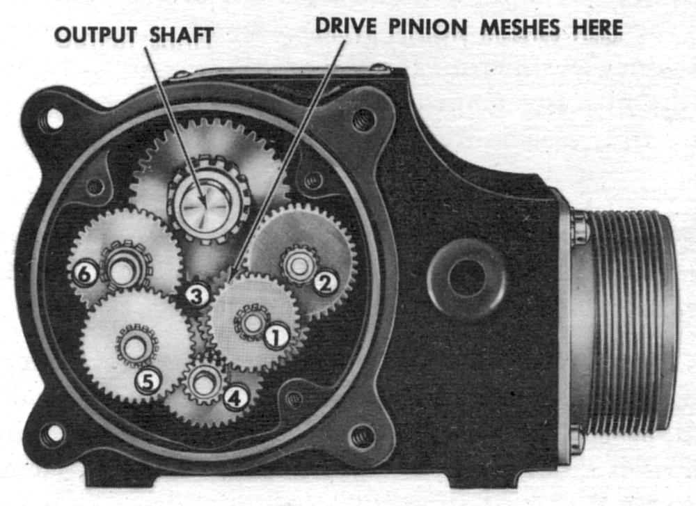
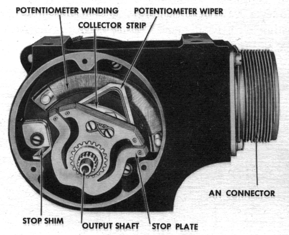
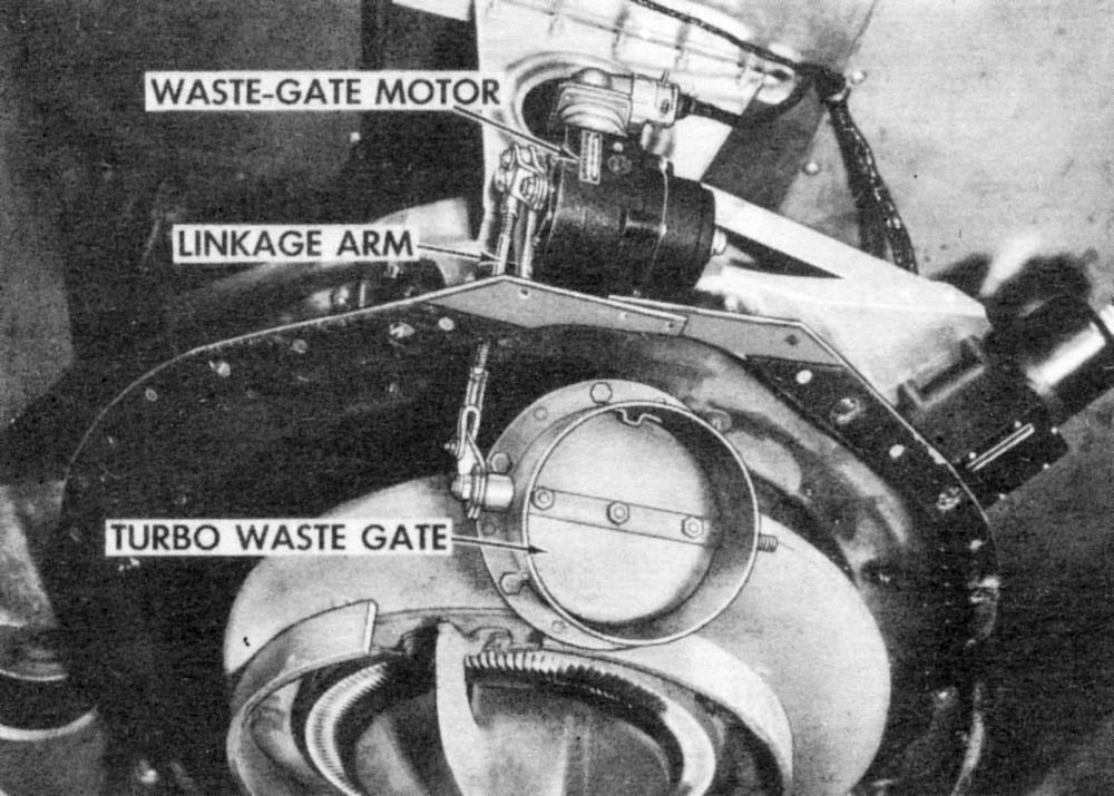
| Fig. 37. Waste-Gate Motor Gear Train | Fig. 38. Waste-Gate Motor Balancing Potentiometer | Fig. 39. Consolidated B-24 Turbosupercharger Waste Gate Operating Linkage | Fig. 40. Waste-Gate Motor Schematic |
The gear train assembly (Fig. 37) was located in the gear housing and provides a speed reduction of 1689:1 It transmitted motor rotation to the crank arm through the bull-gear-and-output-shaft assembly. The gear train was made up of six gear-and-pinion assemblies, mounted on five bearing shafts. One end of each of these shafts was pressed into the gear housing, and the other ends fitted into holes in the armature-assembly mounting plate. The six gear-and-pinion assemblies were driven by the drive pinion on the armature shaft.
The gear housing contained a quantity of oil that allowed the lowest gears to run in oil and lubricate the other gears. A felt disc against the armature assembly mounting plate lubricated the drive pinion, gear-train shafts, and bull-gear end of the output shaft. This oil also lubricated the rear armature-shaft bearing. It seeps into the stator housing, and a felt disc at the rear of the housing carried oil to the bearing. An oil plug (33 in Fig. 34) was provided for draining or refilling the gear case. A neoprene seal around the output shaft kept oil from leaking out of the housing's lubricated portion.
The potentiometer (Fig. 38), located under the cover plate in the gear housing, was the balancing potentiometer of the electrical control circuit. The potentiometer assembly, consisting of a semi-circular winding (1 in Fig. 34) and a collector strip (3), was held in place by three mounting screws. The stop-plate-and-wiper assembly (2 and 4) was splined onto the output shaft (11), and moved with the crank arm. The wiper (2) contacted both the winding and the collector strip. Mechanical stops in the gear housing (34) limited crank arm rotation to 90°, and the stop plate was constructed so as to absorb the shock of striking the stops.
The crank arm (5 in Fig. 34) was a double steel arm to which the waste-gate linkage was attached. The crank arm fitted over the splined output shaft, and was tightened on the shaft by a nut (6). It was adjustable in steps of 22.5°, permitting the crank arm to be placed in the most advantageous position relative to the waste-gate arm (Fig. 39).
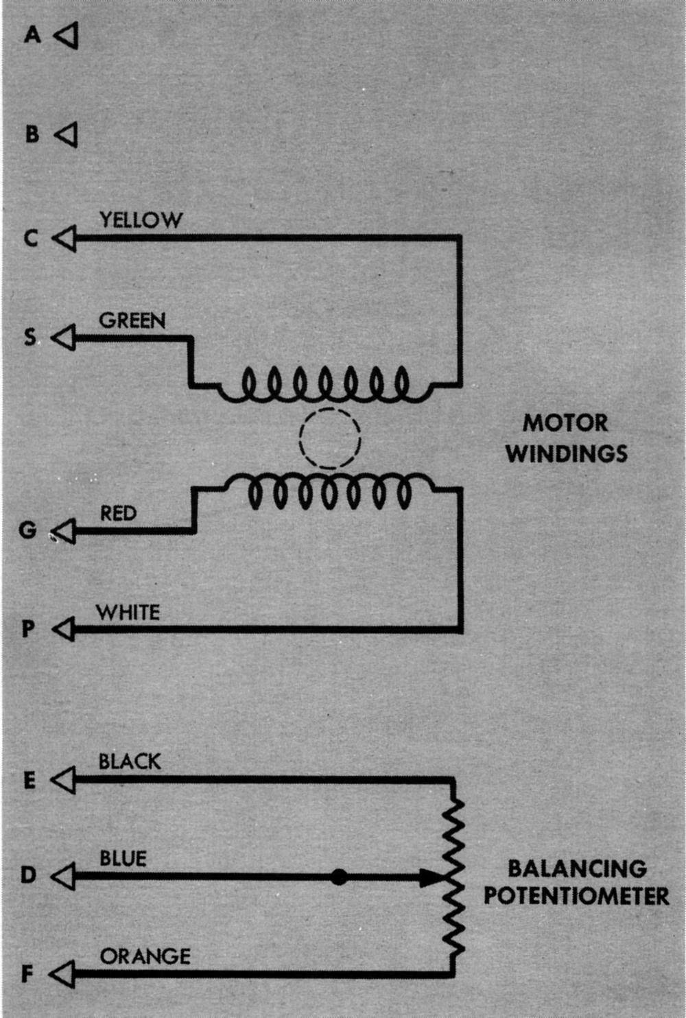
The waste-gate motor internal wiring is depicted in Figure 40. Twelve volts impressed on the potentiometer was supplied by one of the nacelle junction box transformer secondary windings. The potentiometer resistance was 925 ± 13% ohms and the wiper tension was 15 to 35 grams. The two-phase motor winding resistance was 50 ohms; the 115VAC 400 cycle applied voltage developed 325 (+75, -10) VAC in the fixed-phase windings and 200 (+25, -10) VAC in the amplifier phase windings. Maximum armature speed was 12,000 rpm with a rated torque of 50 pound-inches.
Nacelle Junction Box
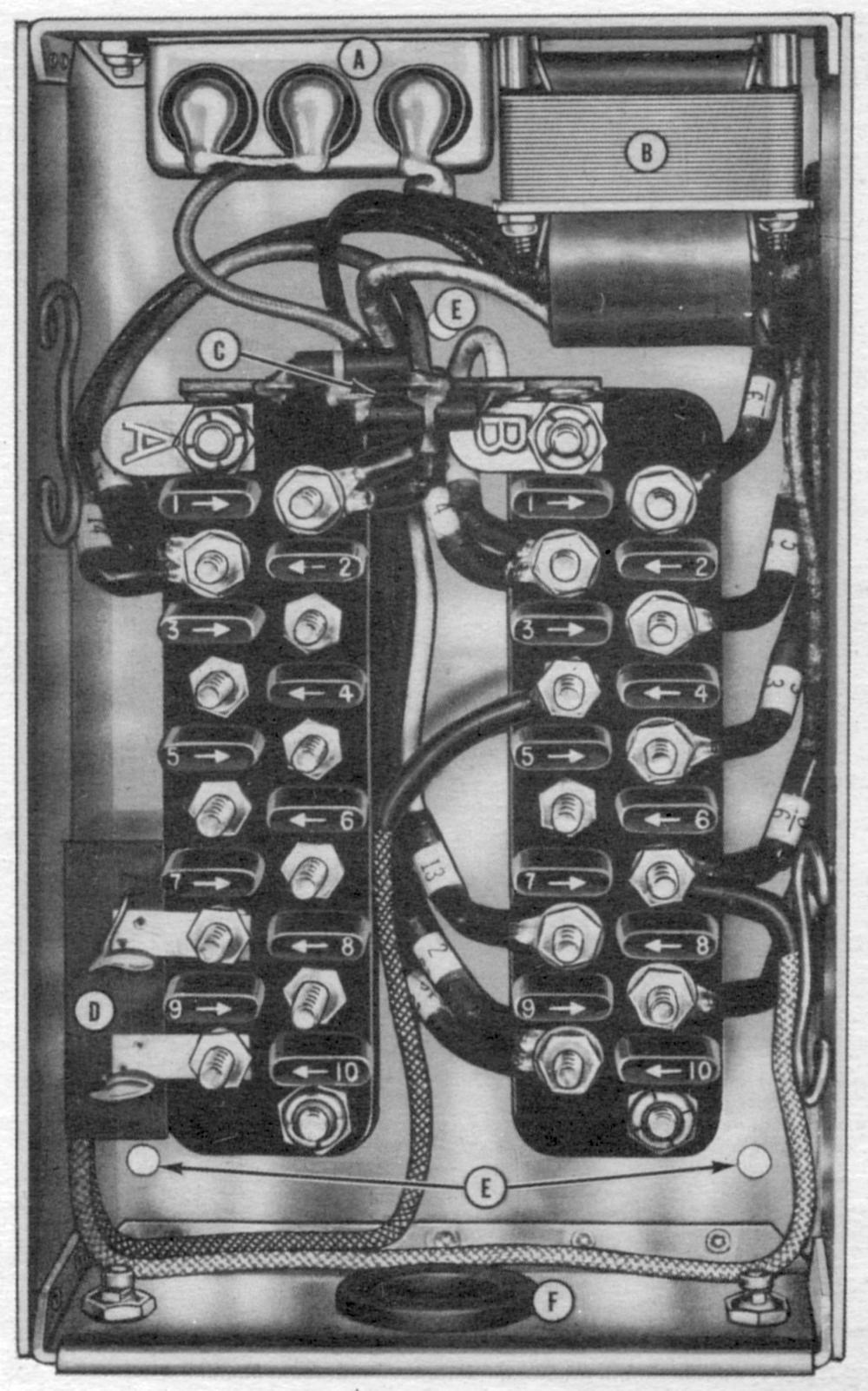
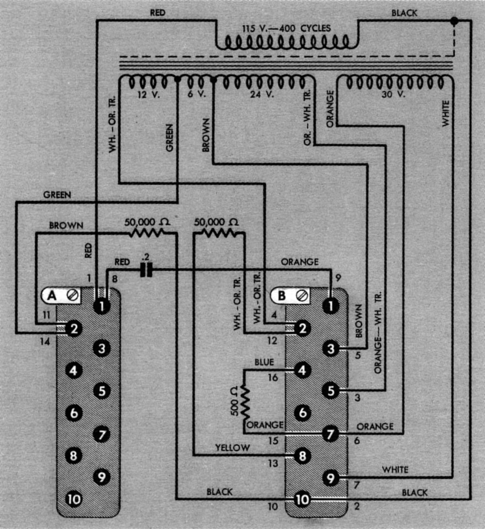
The nacelle junction box (Fig. 41), located within the engine nacelle, provided interconnection for the Pressuretrol, governor, waste-gate-motor leads, and the main junction box. Two terminal blocks within the unit had ten terminals each. The blocks were identified by the letters A and B stamped on metal tabs attached to the blocks. The terminals were identified by numbers from 1 to 10 on the bakelite dividers adjacent to each terminal post. The nacelle junction box was also a convenient place for locating a transformer (B), a condenser (A), and three resistors employed in the control circuit. The transformer was wound with two secondaries. The 30 VAC secondary supplied voltage for the Pressuretrol and accelerometer potentiometer. The other secondary supplied a total of 42 VAC, of which 12 VAC was applied to the waste-gate-motor balancing potentiometer, and 24 VAC to the overspeed potentiometer. The 6 VAC portion, between the 12 and 24VAC sections, was not impressed on any potentiometer, but was used to balance the control system electrically so that the calibrator potentiometer wiper would be near the center of its winding during normal operation. Two 0.1-microfarad condensers, in parallel with each other and assembled in one case to form a 0.2microfarad unit (A), were connected in series with the waste-gate motor line-excited winding. Two 50,000-ohm resistors were mounted on a card (C) between the upper ends of the two terminal blocks. These were the protective resistors that caused the waste gate to open if contact was broken between any wiper and its potentiometer winding.
Another 500-ohm resistor on card (D) fastened to terminals A8 and A10. It was connected between one end of the accelerometer potentiometer winding and its wiper, and prevented an open circuit in case vibration caused intermittent wiper contact.
A hole with rubber grommet (F) was provided on one end of the unit for bringing in external wires.
There were three mounting holes (E) in the bottom of the box. The cover was held in place by two Dzus fasteners. Sixteen wires leading to the transformer, condensers., and resistors within the nacelle junction box comprised its internal wiring (Fig. 42).
 |
 |
| Fig. 41. Nacelle Junction Box | Fig. 42. Nacelle Junction Box Schematic |
Main Junction Box
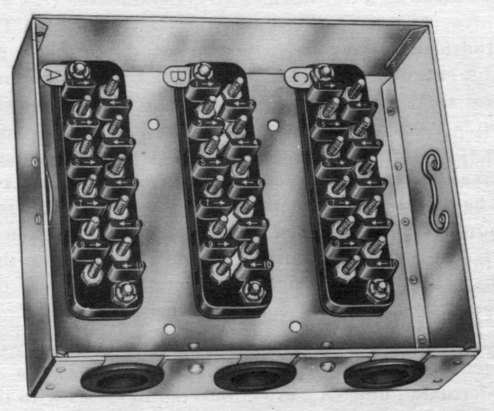
The main junction box (Fig. 43) was used for interconnecting the various control system components. It consisted of an aluminum box containing three terminal blocks of ten terminals each. The blocks were marked A, B, and C by identification tabs. The terminals were identified by numbers from 1 to 10 on the bakelite dividers adjacent to each terminal post. Terminals B1, B2, B3 and B4 were connected together at the block by metal links. Terminals B7 and B8, as well as B9 and B10, were also connected by metal links.
An aluminum cover was held on by two Dzus fasteners. An envelope fastened to the main junction box inside of the cover contained a system wiring diagram, a troubleshooting procedure, and a diagram of all wiring connections within the main junction box. Three wiring holes in one side of the box were provided with rubber grommets. Four mounting holes in the bottom allowed the unit to be bolted to the airplane.
 |
| Fig. 43. Main Junction Box |
Send mail to
![]() with questions or comments about this web site.
with questions or comments about this web site.
![]()