
Harbor Freight
Engine Stand
Like my other drone engine stands, a $75, 1,000-pound capacity engine rebuilding stand from Harbor Freight was the starting point (left).
Restoring the 1944 Righter 4‑O‑34 Engine to Running Condition
Part 2: Engine Mount and Running Stand
by Tom Fey
Published 1 Jul 2022
| Part 1: The Engine | Part 2: Engine Mount and Running Stand | Part 3: Running the Engine |
Harbor Freight Engine Stand |
There were three major criteria for building up a running stand for the 17-horsepower, 35-pound, 1944 Righter 4-O-34 engine. First was strength/safety, second was that it could be no taller than the 44-inch interior height of my wife’s Honda Odyssey, and third was it had to break down into two pieces so I could carry it down the stairs to overwinter in my basement. Like my other drone engine stands, a $75, 1,000-pound capacity engine rebuilding stand from Harbor Freight was the starting point (left). |
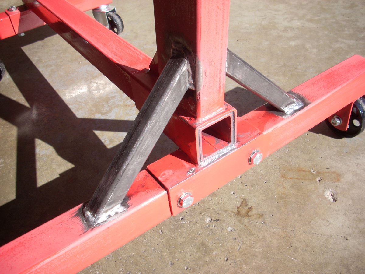
The next stop was my welder. The rotatable/removable trunnion was welded in place to the stand and a 10 x 4 inch, 0.125-inch-thick flat steel plate welded to the back of the vertical member to provide a mounting pad for a fuel tank and electric fuel pump. I told my structural engineer son I wanted to have support struts welded between the vertical and horizontal components. He looked over the mocked-up stand, asked a few questions, and said “completely unnecessary, Dad”. This made me happy. And I did it anyway (Pic 2).
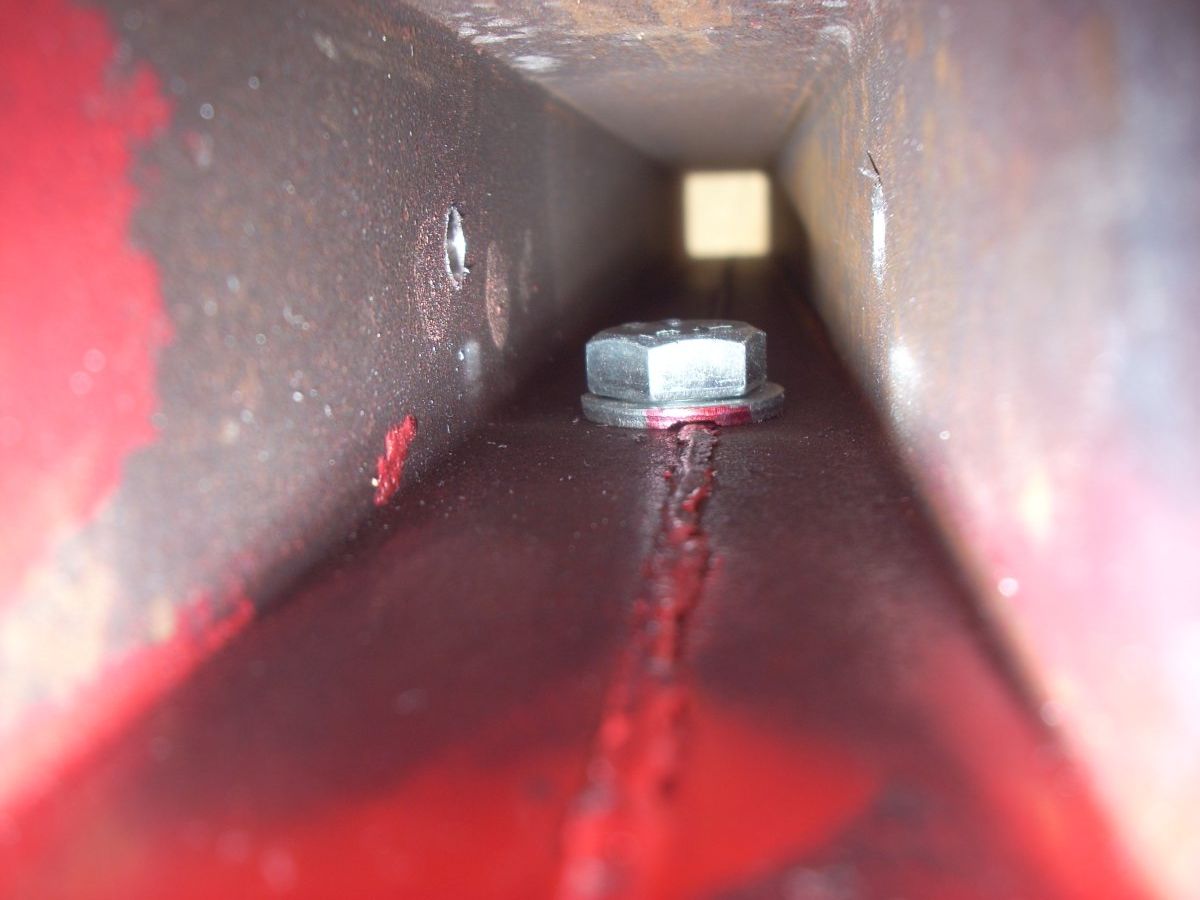
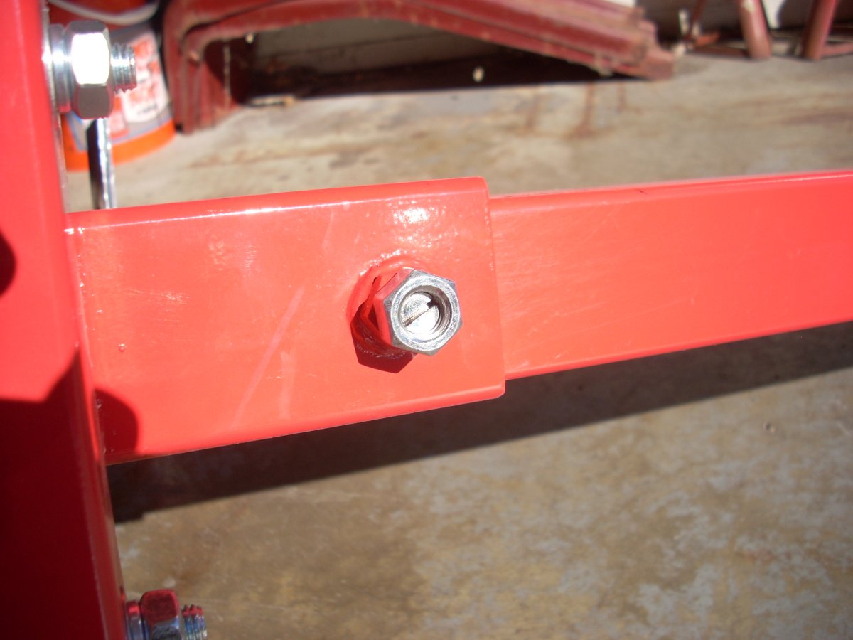
The original stand used a beefy bolt through a welded nut on underside of the rear receiver as a grub screw to secure the front arm to the loose-fit receiver of the rear stand. I reversed the intended direction of the bolt, drilled a hole through the square tube of the front arm and fed the bolt from the inside of the front arm and threaded it into the welded nut. I had to relive the washer to accommodate the seam in the tubing. Cutting a slot into the end of the bolt allowed me to tighten if from the outside of the stand with an impact driver and lock it with a second nut (Pics 3, 4). I also drilled horizontally through the receiver box and front arm to tie them together using a stainless through-bolt and fiber lock nut.
I removed the front axle tube and bolted a wood 4x4 in its place to keep it from skittering around during fabrication. Ultimately an extra piece of 2-inch square steel tube was purchased to broaden the track of the front axle to 27 inches, same as the rear track, for improved stability (Pic 5).
 |
 |
 |
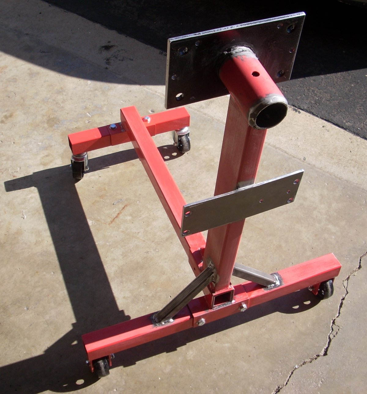 |
| Pic 2. One-inch square support struts welded to engine stand. Front tube welded at bottom to receiver, space filled with JB Weld epoxy. | Pic 3. Bolt inside front tube threads into nut welded on the receiver bottom . | Pic 4. Receiver bottom showing extra silver nut locked against the welded red nut on the receiver. | Pic 5. Front and back trunnion, struts, receiver, and fuel tank flat plate welded to the stand. |
A major key to a safe running structure is the use of rubber isolation mounts to secure the engine to the running stand. I know of at least two propellers that have exploded when 8 horsepower drone engines had been hard-mounted to a running bench/stand. These simultaneously-firing engines buzz and waddle quite a bit.
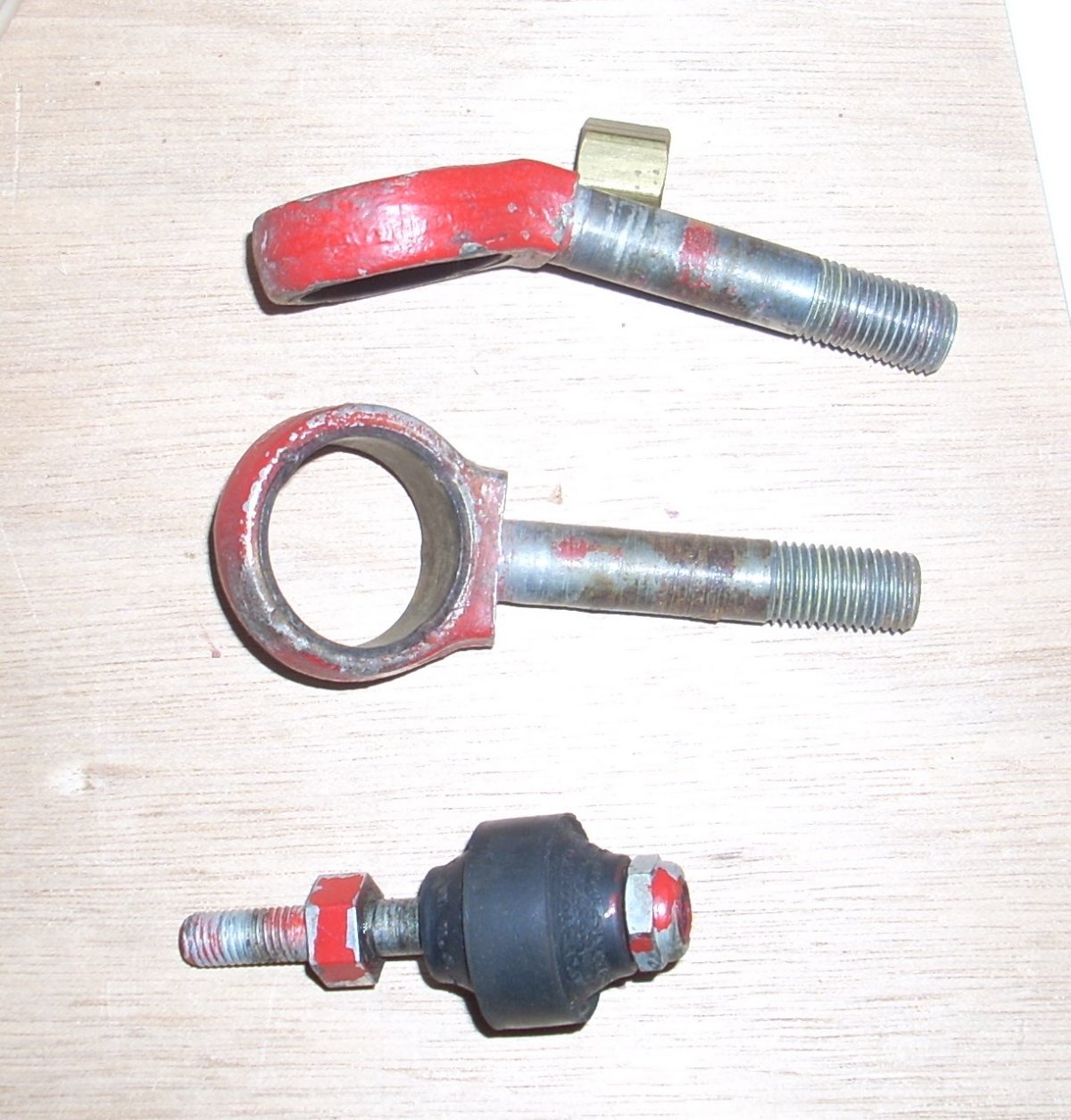
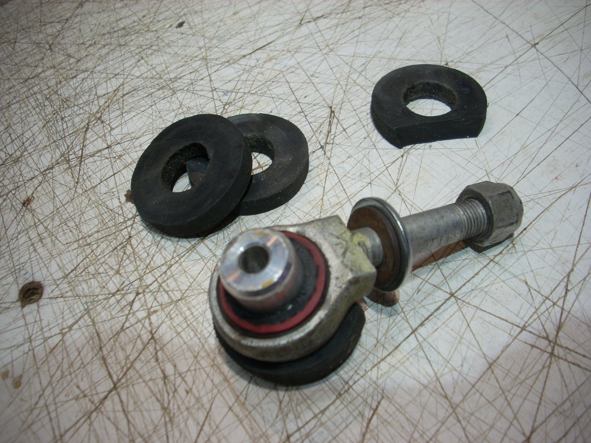
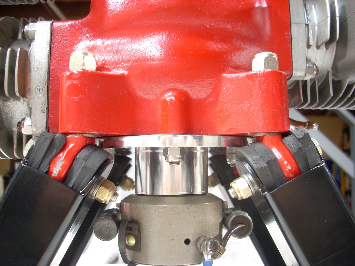
The original forged steel Lord mounts are difficult to find, and if found, the 78-year-old rubber has dried, cracked, and delaminated from the eye of the bolt (Pic 6). With reluctance I scavenged a set of original angled mounting eyebolts from a drone engine QEC (Kiekhaefer 0-45-35 in a tube mount for a Globe KD4G) in my collection. My intrepid A&P rebuilt the isolation mount eyes using an aluminum spacer and aircraft fuel tubing as the vibration damper, all to be sandwiched in the clevis with neoprene washers (Pic 7). It is a tight pain to assemble, but a proven and sturdy design (Pic 8).
My trusted A&P also fabricated engine mounts from 1.5-inch square tube of 0.125-inch wall thickness welded to a pair of hefty 3/8-inch-thick steel backplates. The mount arm ends were relieved and drilled to form clevises. The two backplates will be secured to the trunnion backplate (0.425 inch thick) with six AN5 (5/16-24) aircraft bolts, providing for disassembly of the running stand to two components (Pic 9). The mounting system passed the traditional “Tom Test” which means it will undergo minimal deflection while holding my considerable body mass.
 |
 |
 |
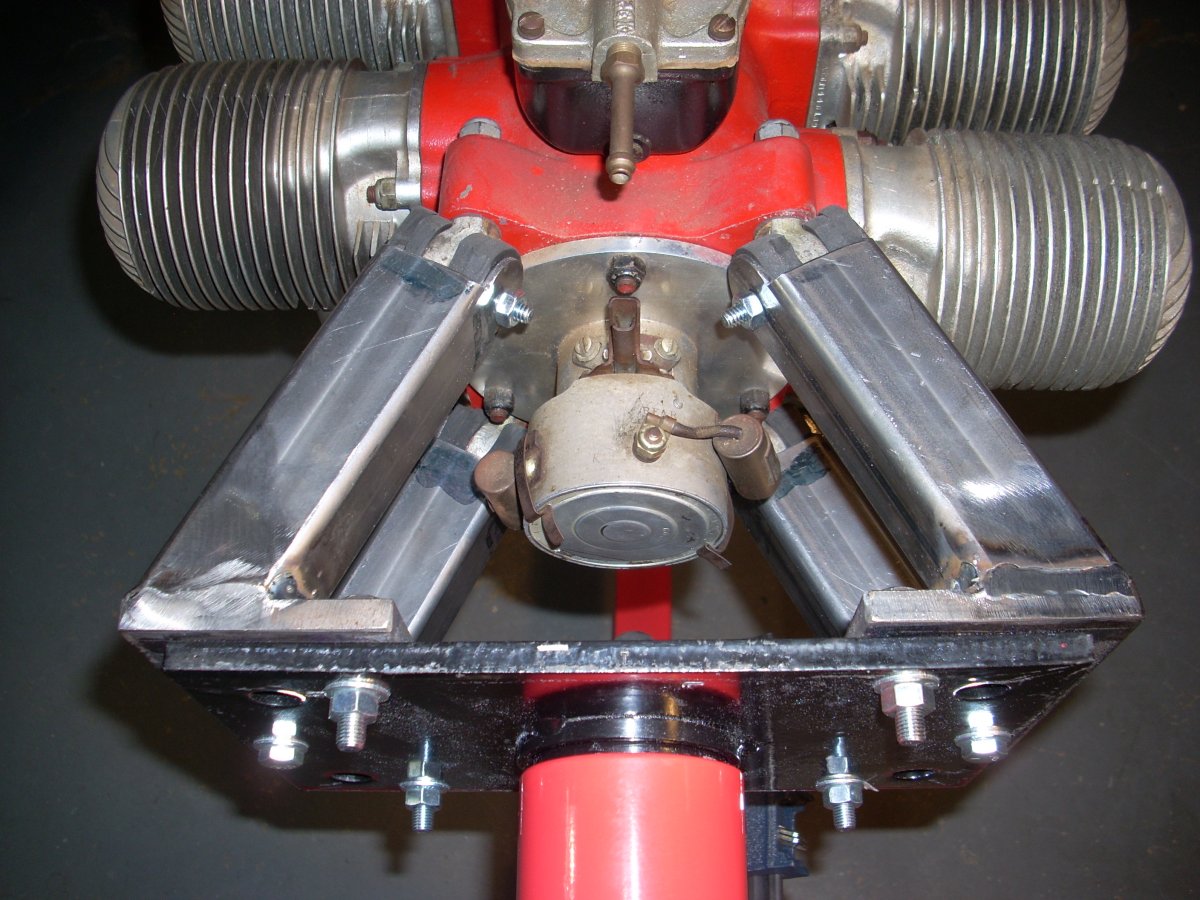 |
| Pic 6. Original forged 27° angle eyebolt with the aged rubber isolation component (Lord M-1001-E) loose from the eye. Rubber was glued to a steel ring, which was then staked into the forged eyebolt | Pic 7. Reconstructed isolation mount with central aluminum spacer trapped by fuel tubing inside the bolt eye. Neoprene washers keep the eyebolt centered in the clevis. | Pic 8. Isolation mounts in place. | Pic 9. Square tube engine mount struts were angled to mimic the original drone airframe geometry and provide access to the ignition timer. |
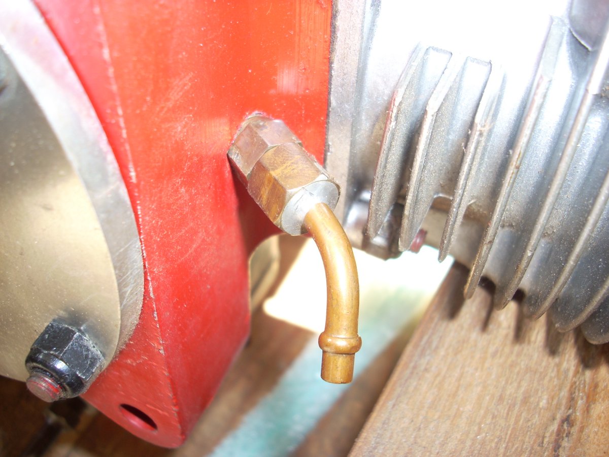
Most drone engines of this vintage used pressure (about 2 psi) tapped from the crankcase to pressurize a fuel tank located behind the engine on the aircraft center of gravity (Pic 10). Running on pressure requires an air-tight system and perhaps difficulty in getting fuel to the engine for starting. While the vintage drone engines will run with a 24-inch pressure head, that wasn’t practical for my installation. Instead, a 12-volt K&N model 81-0401 fuel pump that delivers 25 gallons per hour at 1 to 4 psi with a built-in backpressure limit system was installed (Pic 11). The 4-O-34 burns 2.5 gallons per hour at wide open throttle.
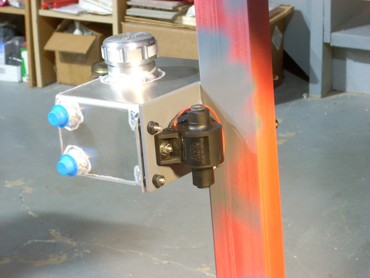
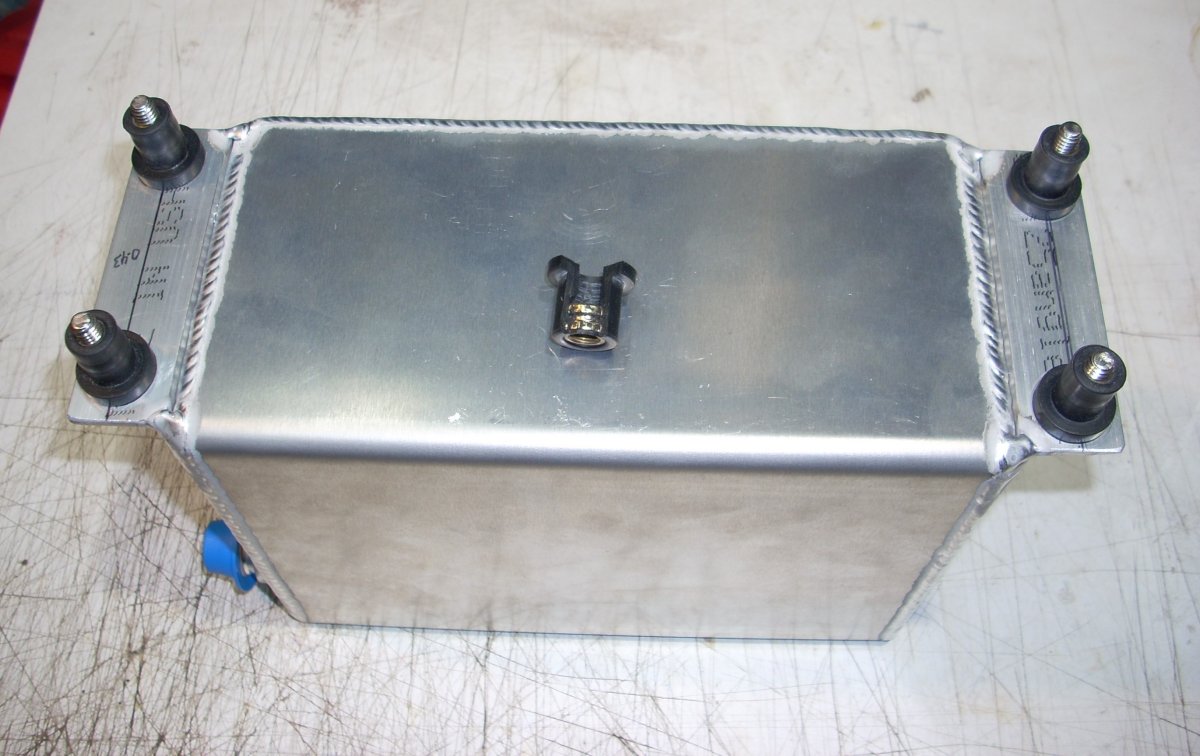
I purchased a welded aluminum 0.5 US gallon fuel tank from Boyd Welding which has AN inlet/outlet fittings. I found rubber well-nuts at the hardware store which provided a modicum of vibration isolation and provides 3/16 inch of stand-off gap between the tank and the steel mounting pad (Pics 12, 13).
 |
 |
 |
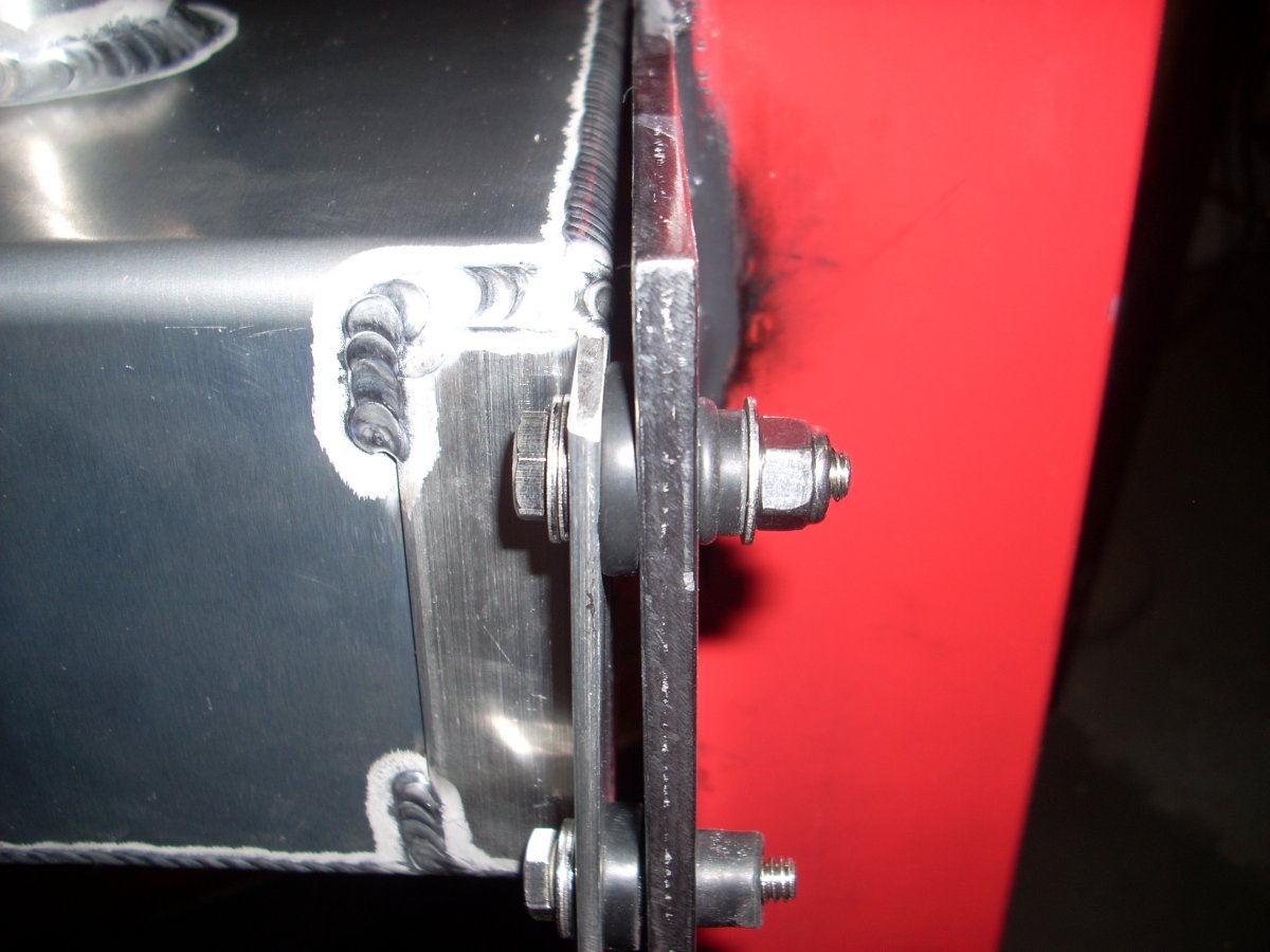 |
| Pic 10. Crankcase pressure tap has a one-way ball and spring check valve to prevent fuel backflow into the engine. I soldered this closed. | Pic 11. Electric fuel pump trial mounted on stand. | Pic 12. Fuel tank aft face showing rubber well nuts in the mounting bracket. A cutaway well nut showing bonded brass insert inside the rubber sleeve rests on the tank. | Pic 13. Mounted tank showing upper well nut tightened with safety washer and nut behind the well nut. Lower well nut has not been tightened. |
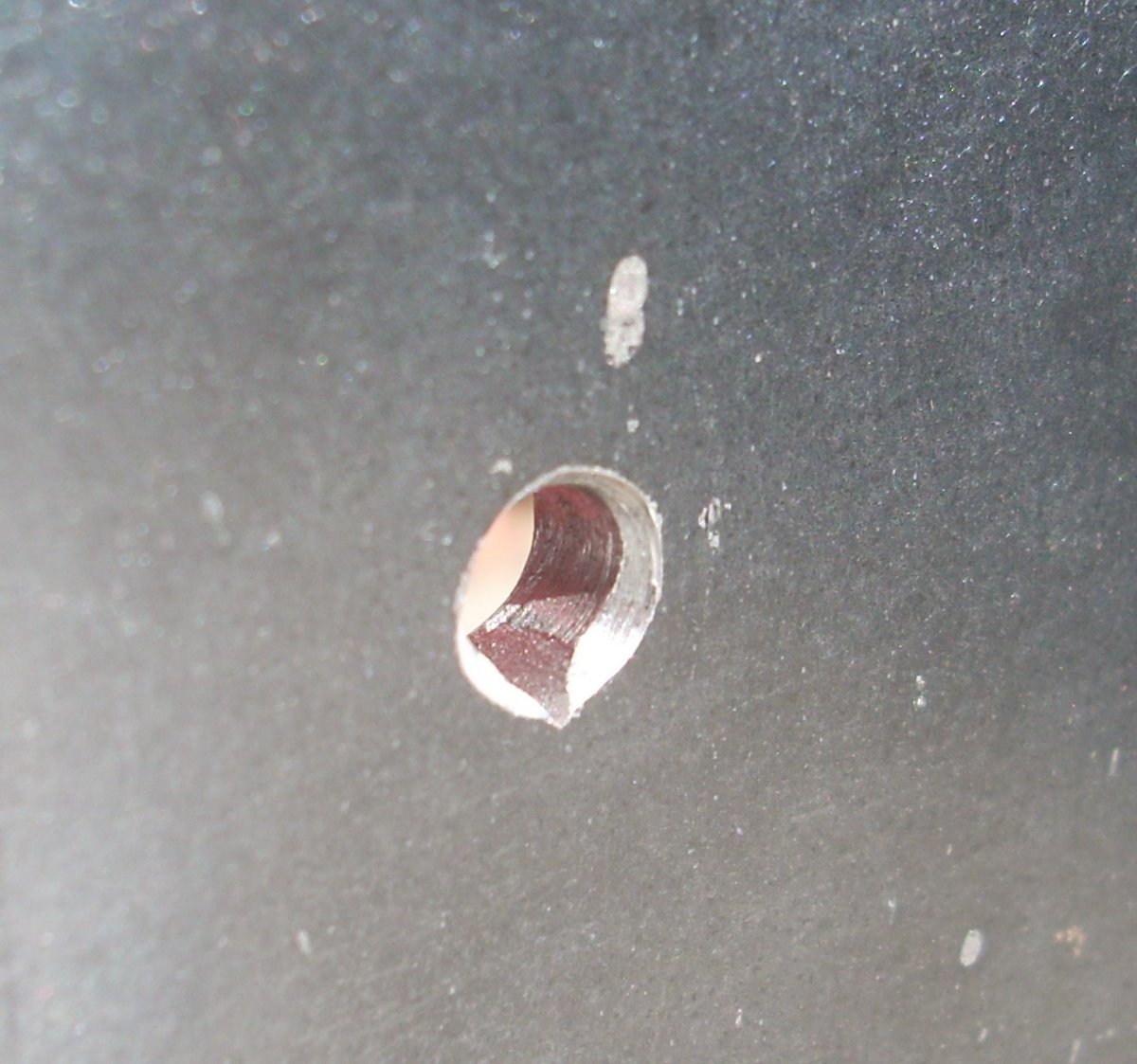
The fuel pump was mounted on the opposite side of the fuel tank using modified stainless steel carriage bolts. The carriage bolt heads were ground flat from their typical domed shape and three of the four “points” on the underside of the bolt head were removed with a Dremel tool cutting wheel. A triangular file was used to cut a single “point receiver” in the steel plate so that the modified carriage bolt securing the fuel pump to the plate would not rotate when the nuts were tightened (Pic 14). The head was flat enough to reside in the gap between the tank and the mounting plate without fouling the fuel tank.
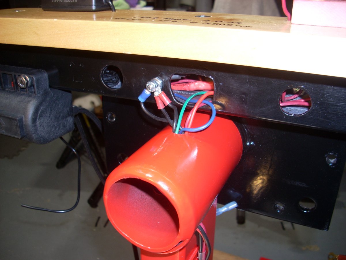
The 2-inch square steel tube front axle was repurposed by bolting to the aft side of the trunnion backplate, providing a conduit for the wiring, a place to hang the two dual coils, and a mounting pad for an instrument panel made from the leftover ¾ inch white birch board used to laminate the propeller (Pic 15). Drills and a 3/8-inch diameter end mill in a drill press was used to cut the required holes in the mounting tube and a Dremel tool grinder rounded all the sharp edges. The stand is maneuvered around and lifted using the instrument panel as handholds, so sturdy is mandatory.
The front pair of opposed cylinders on the 4-O-34 are simultaneously-firing, as are the rear cylinders firing 180° later. Aftermarket 5 Ohm dual coils for a Harley-Davidson motorcycle were acquired, one coil for the forward cylinders, one coil for the aft cylinders, each controlled by their own set of ignition points and condenser (Pic 16). The plug wires are 7 mm cotton braided, copper core wires sourced from Brillman.
Wiring the stand, fuel pump, and dual coils was fairly straight forward (Pic 17).
 |
 |
 |
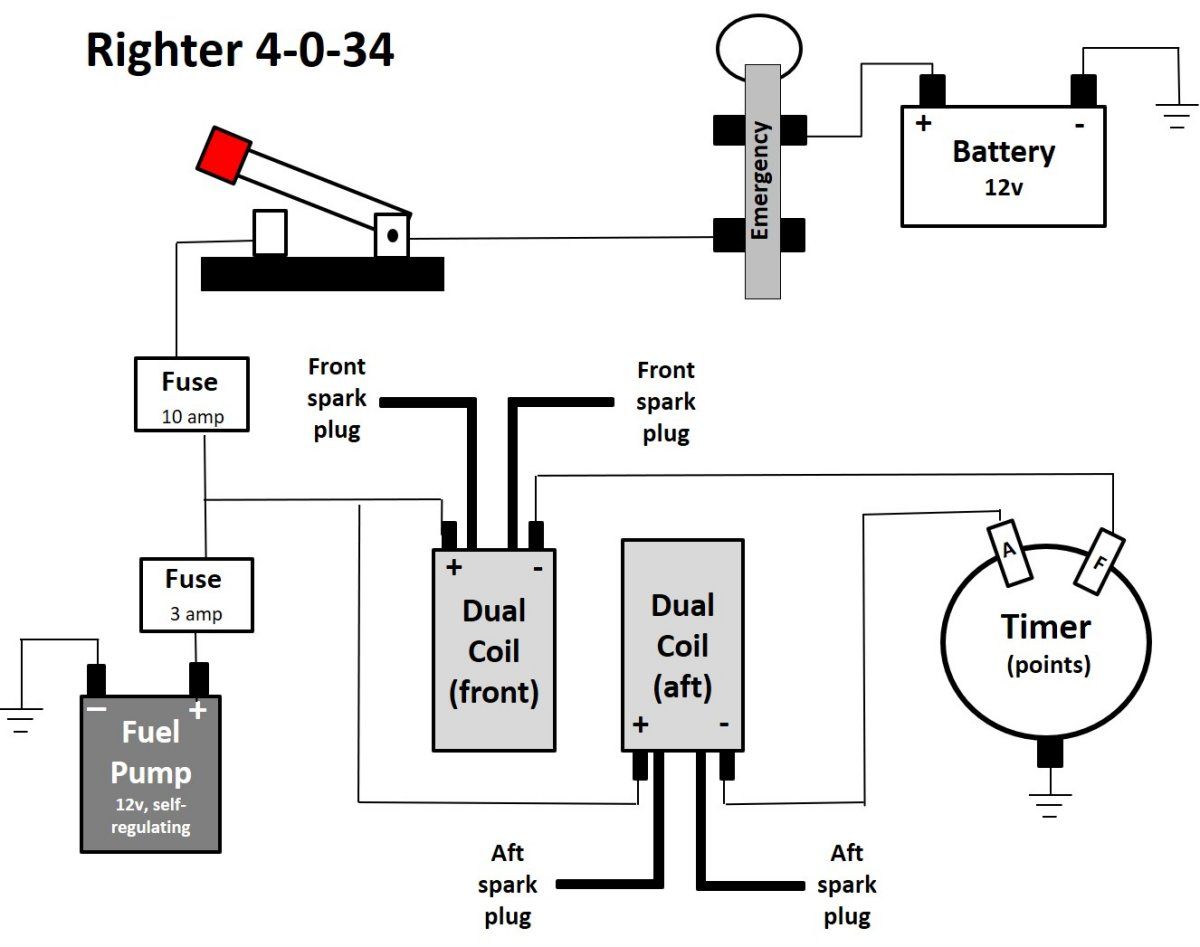 |
| Pic 14. Hole in mounting plate showing triangular relief that restrains the modified carriage bolt from turning. | Pic 15. Black square tube above the trunnion receiver and below the wood provides access to the upper mount bolt heads, a secure mounting surface for the instrument panel, and a conduit to run wiring. | Pic 16. Aftermarket dual coil is bolted to the square tube that anchors the instrument panel. | Pic 17. 4-O-34 running stand wiring schematic. |
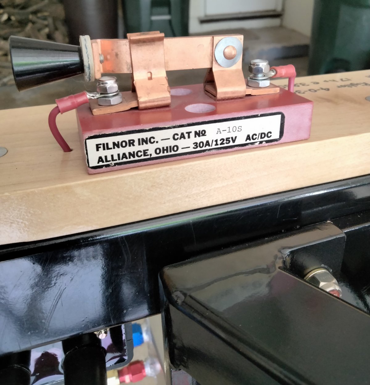
The engine cannot fire without a battery, but hand-priming and hand-starting the engine, which now fires every 180°, presents significant risk to any person moving the propeller. That person has to know when the system is hot. Which explains the large knife switch = anti-stupid device on the panel (Pic 18). When it is open, it is safe to rotate the propeller. Switch closed, the engine is enabled to run. My earlier running stands used an illuminated arming switch, but this proved inadequate on bright sunny days.
The propeller is indexed so that top dead center is when the propeller is vertical, which is an ideal geometry for hand-propping the engine.
The 12-volt electrical system has a 10-amp fuse for the whole system and the recommended 3-amp fuse for the fuel pump. An emergency cut-off switch was fashioned from an old-style automotive glass fuse holder and a lynch pin. Anyone can pull the cord from a safe distance to kill the engine and fuel pump.
The carburetor on this particular 4-O-34 has a spring-loaded choke but no throttle. It was designed to run wide open. However, engine speed can be controlled by the mixture needle on the top of the carburetor and the manual spark advance lever on the back of the engine which rotates the timer (points assembly) up to 27 degrees of advance. The engine won’t rev past 2,200 rpm with the ignition timing set to fire at piston top dead center.
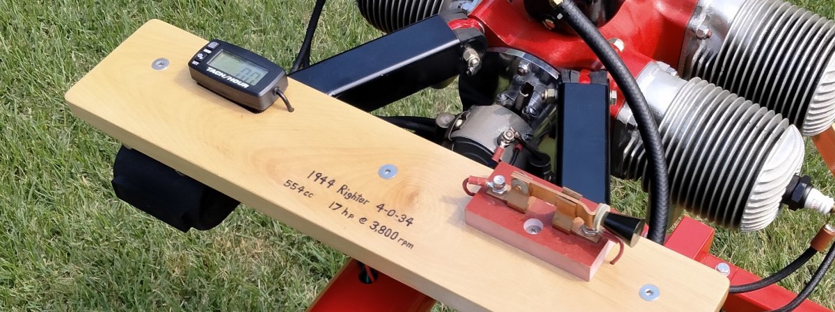
A Searon coin-cell battery powered tachometer/Hobbs meter was installed on the instrument panel with hook and loop fastener and the tach sensing wire fed through the panel and wrapped three times around one spark plug wire. These devices count the spark impulses and can be set for various ignition conditions. In my case it is one spark per revolution (Pic 19).
For running on grass, I jump on the stand arms to push the little 3-inch diameter steel wheels into the dirt (organic wheel chocks) and use one 60-pound sand bag draped on each of the four arms to stabilize the stand. A ground screw anchor and nylon tether secure the back of the stand to Mother Earth lest it creep or lean forward when running (Pic 20).
 |
 |
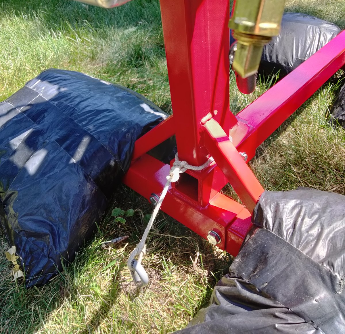 |
| Pic 18. Knife switch provides easy visual reference to status of ignition system power. | Pic 19. Searon tachometer/Hobbs meter is powered by its own removeable battery. | Pic 20. Nylon tether prevents forward movement of running stand. |
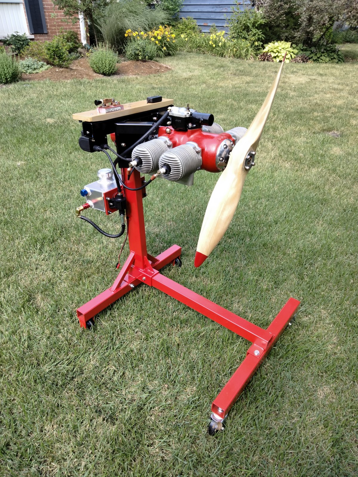
The stand was primed then painted with rattle can Banner Red enamel. Aircraft grade fasteners are used on the propeller, engine, and engine mounting components. The rest is stainless steel nuts and bolts from the hardware store. The completed stand without engine or engine mount weighs about 65 pounds while the engine with engine mount and prop weighs 46 pounds. The complete assembly is 3 feet long, 27 inches wide, and 40 inches tall.
William T. Schwendler was the Chief Engineer for Grumman Aircraft Engineering Corporation during WWII and was a firm believer in strong airplanes to preserve the lives of Navy pilots. During the drop tests on the Grumman F6F Hellcat, the aircraft easily passed the required military specification, and ultimately Grumman winched the aircraft up as high as the building structure would allow without fouling the tail, and it still landed undamaged from nearly double the required height. This 2x “Schwendler Factor” is a guiding principle in my running engine projects.
I alone accept the risks associated with all aspects of running my drone engines. I’m glad to share with people how I did it, but I make no pledge that what I did is correct or ideal.
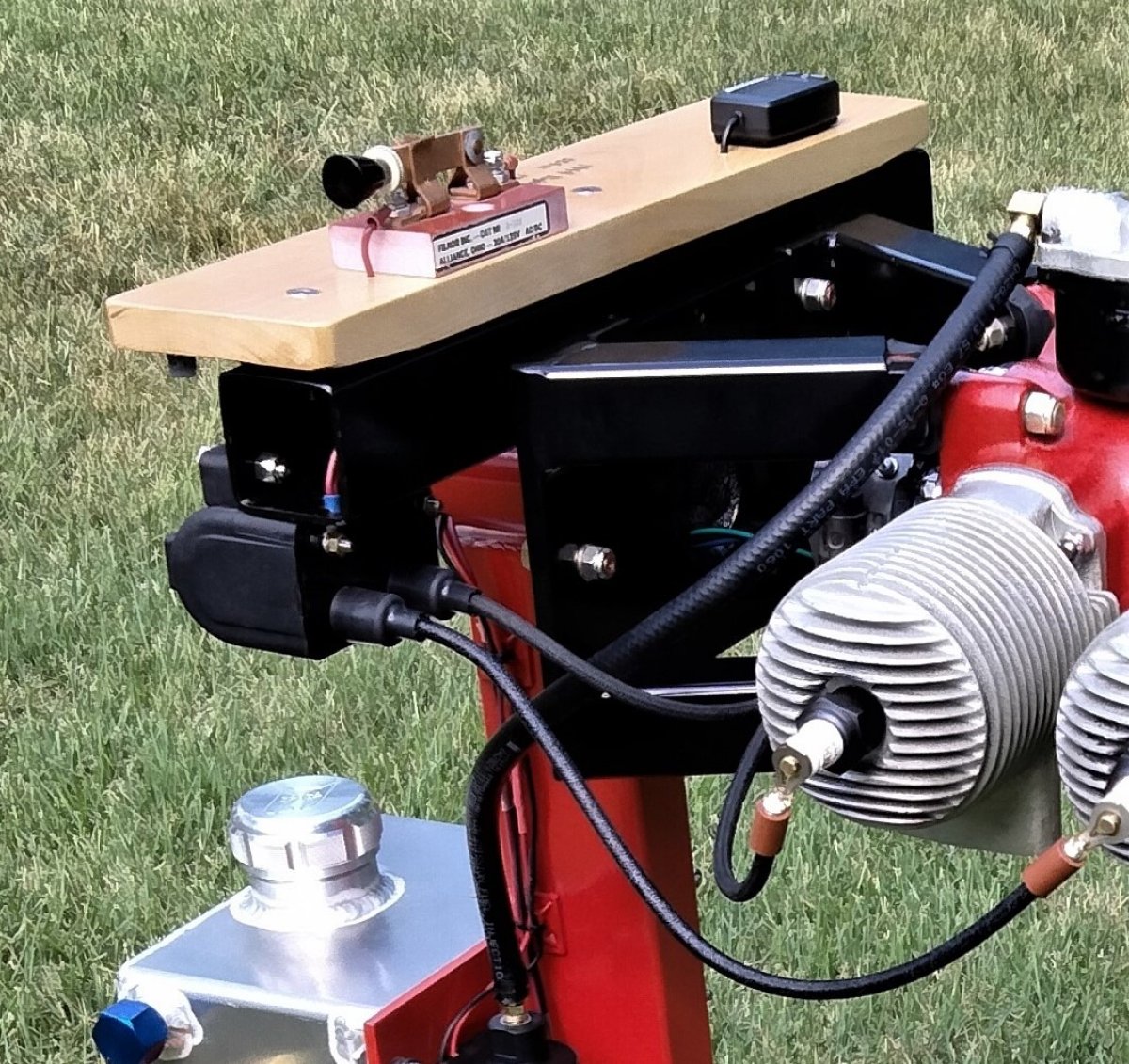
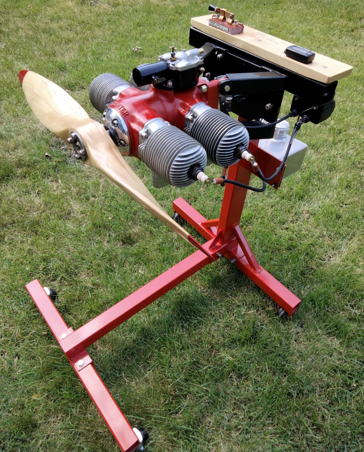
The engine and running stand are now complete (Pics 21, 22, 23).
Next step is smoke and noise!
 |
 |
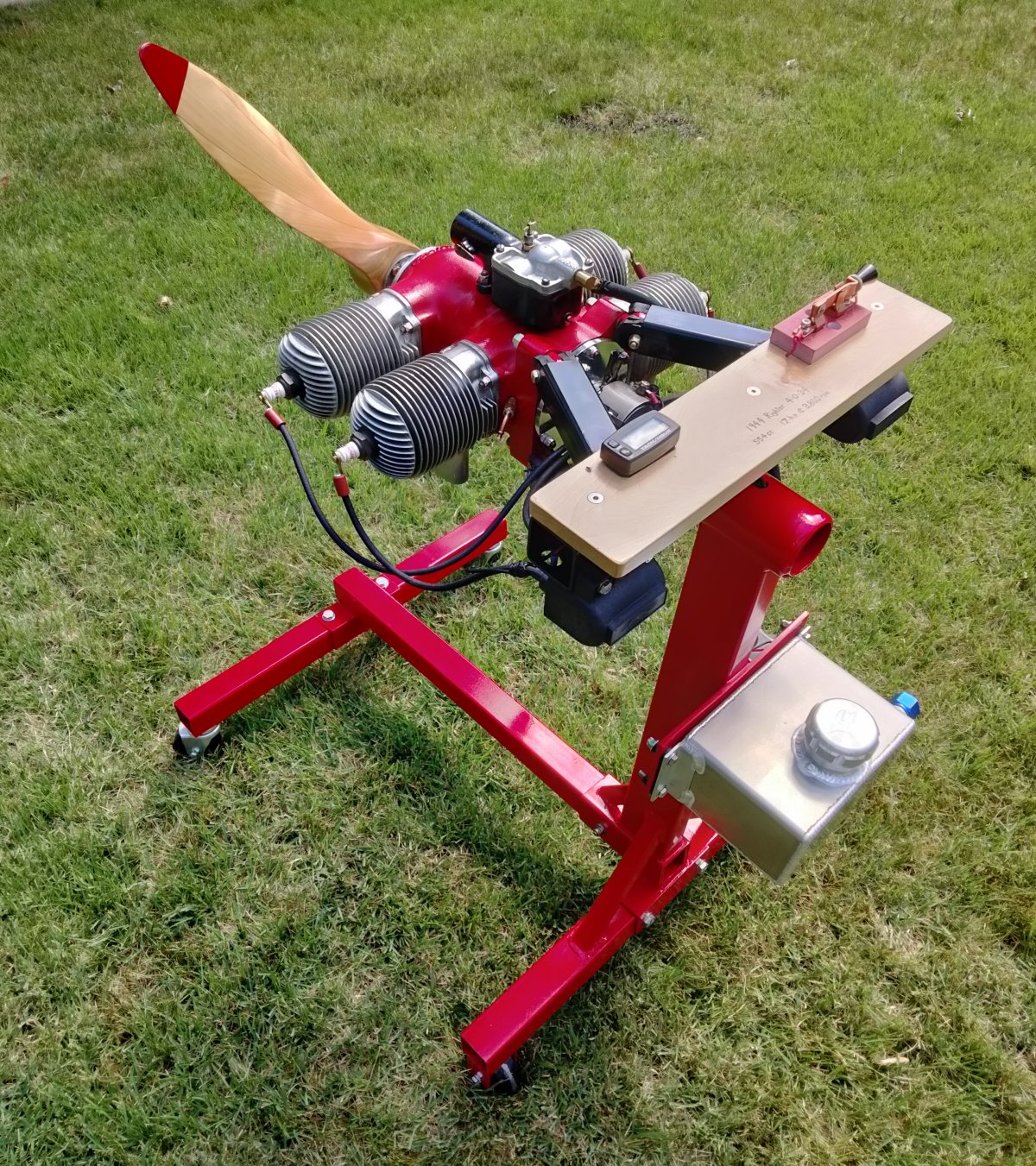 |
| Pic 21. Completed 4-O-34 engine and running stand, which weighs 111 pounds without fuel. | Pic 22. Propeller is 30-inch diameter x 44-inch pitch, constructed from white birch, tailored to a drone design speed of 130 to 140 mph. | Pic 23. 1944/1945 Righter 4-O-34, one of nine made, is ready to run. |
To be continued ...
Send mail to
![]() with questions or comments about this web site.
with questions or comments about this web site.
![]()