Selected Early Engines
Lawrance, Le Rhône, , Liberty, Lorraine-Dietrich
Compiled by Kimble D. McCutcheon
Published 1 Sep 2022; Revised 13 Oct 2022
Lawrance
Charles Lanier Lawrance (30 Sep 1882 – 24 Jun 1950), after graduating from Yale, traveled to Paris, studied architecture, designed the Lawrance-Moulton V-8 race car engine and became interested in aeronautics. He joined the U.S. Navy and at WWI's conclusion founded the Lawrance Aero Engine Company of New York City, New York in 1917. He continued work on Lawrance-Moulton design, developing the Model B V-8 during 1916-1917 along with two air-cooled horizontally-opposed aircraft engines. Next came air-cooled three-cylinder radial that were ultimately developed into the Whirlwind engine series. The Wright Aeronautical Corporation acquired the Lawrance Aero Engine Company in 1923 and Lawrance became the Wright president in 1925 after Frederick Rentschler left to form Pratt & Whitney Aircraft. Lawrance won the 1927 Collier Trophy for "development of radial air-cooled aircraft engines."
Charles Lawrance resigned from the Wright Aeronautical Corporation presidency in 1939 and founded the Lawrance Engineering and Research Corporation (LERC) of Linden, New Jersey. LERC pursued diesel aircraft development, Americanization of the Mawen engine, which had originally been built in France under Sklenar patents, and aircraft auxiliary power plants.
|
|
| Lawrance-Moulton Model A, B (AEE) | |
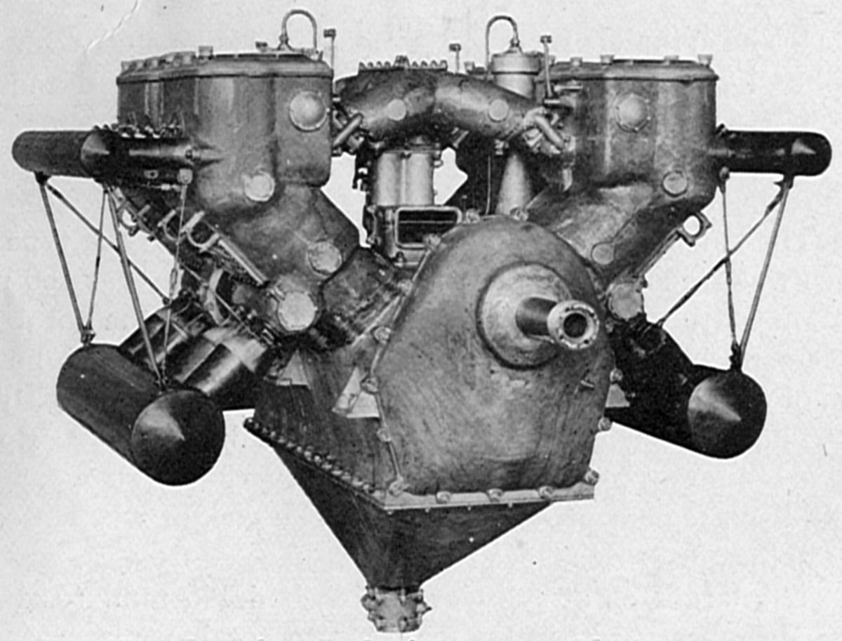
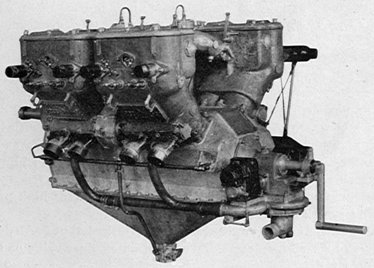
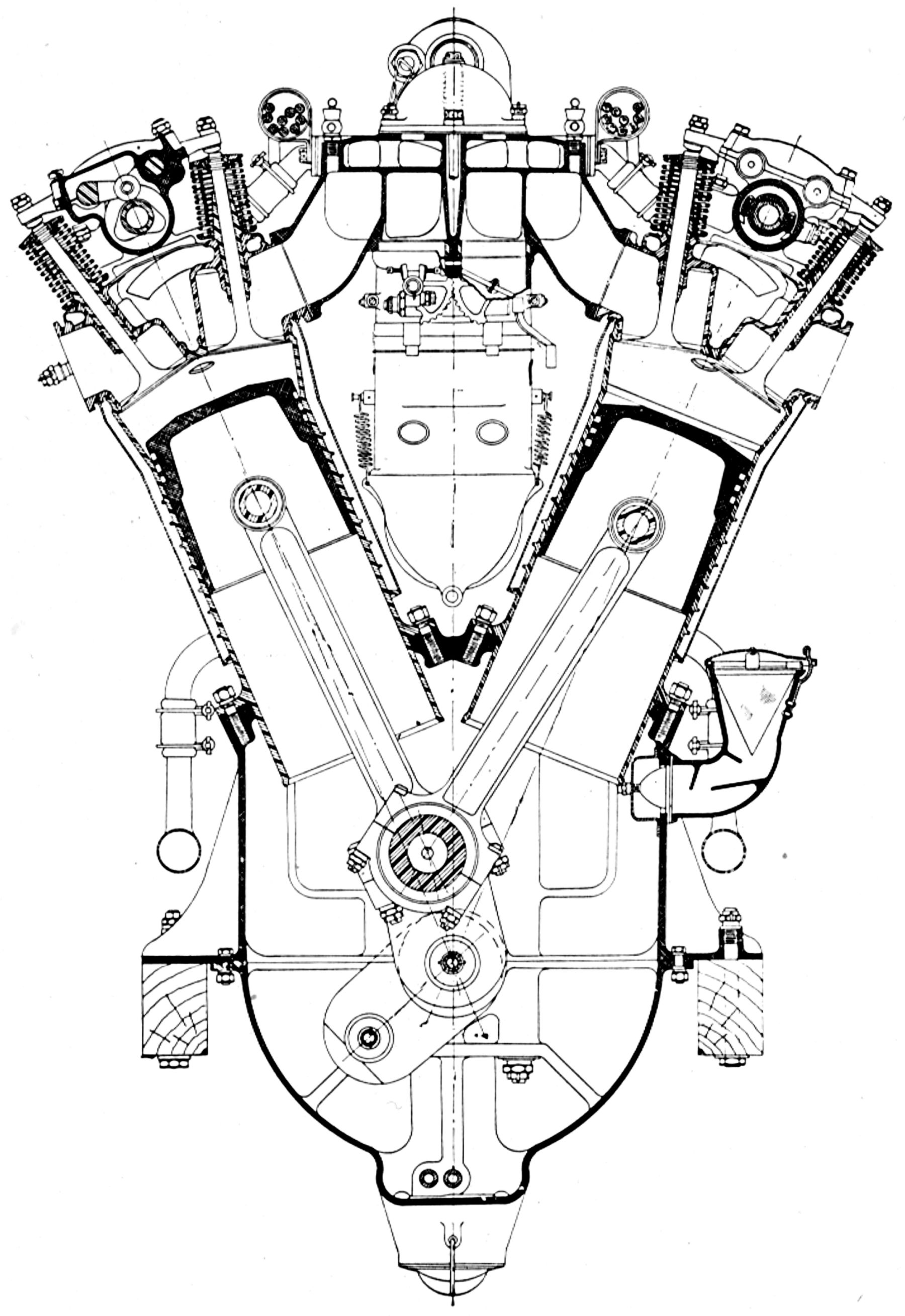
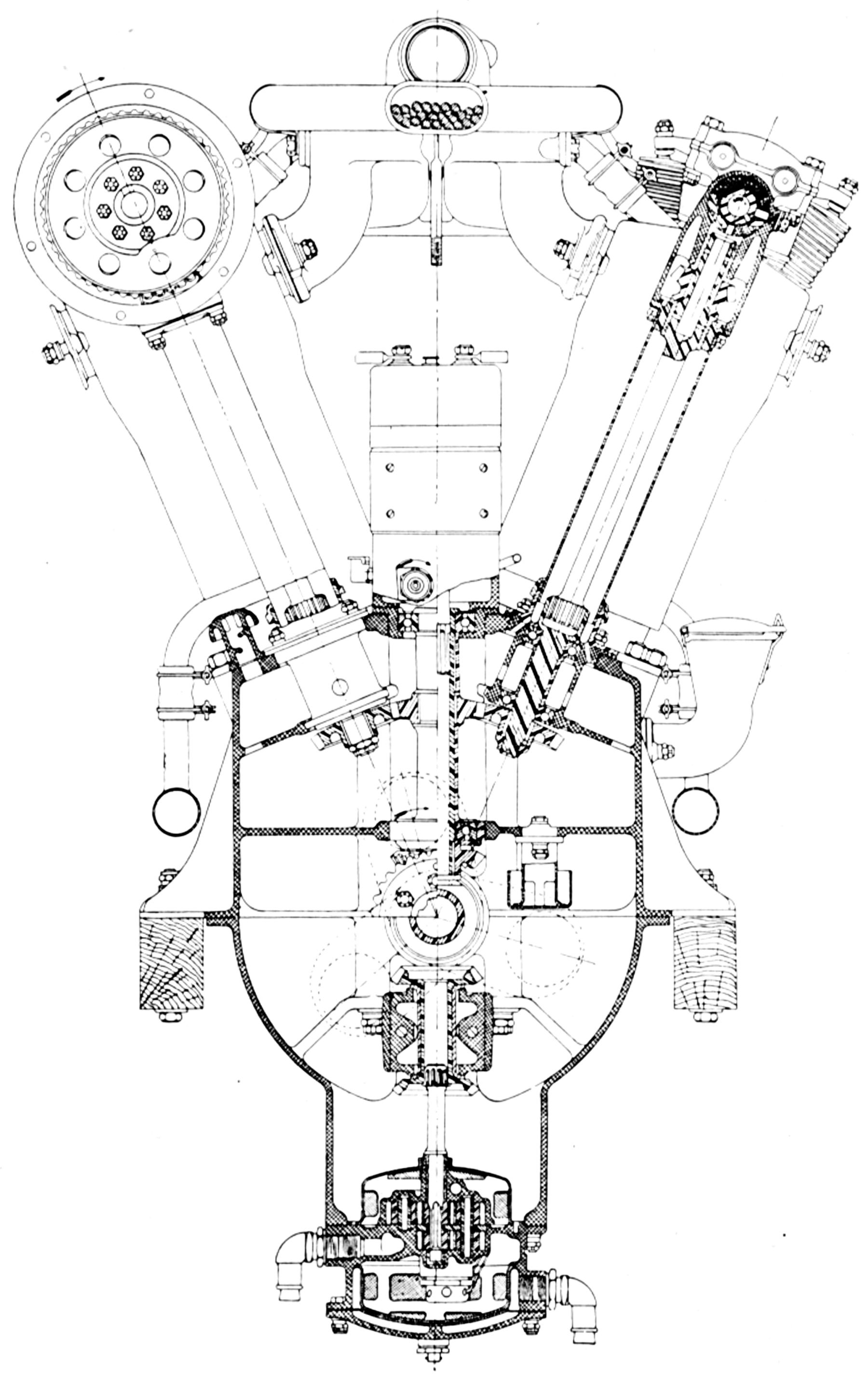
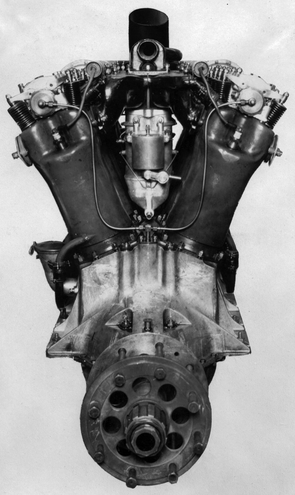
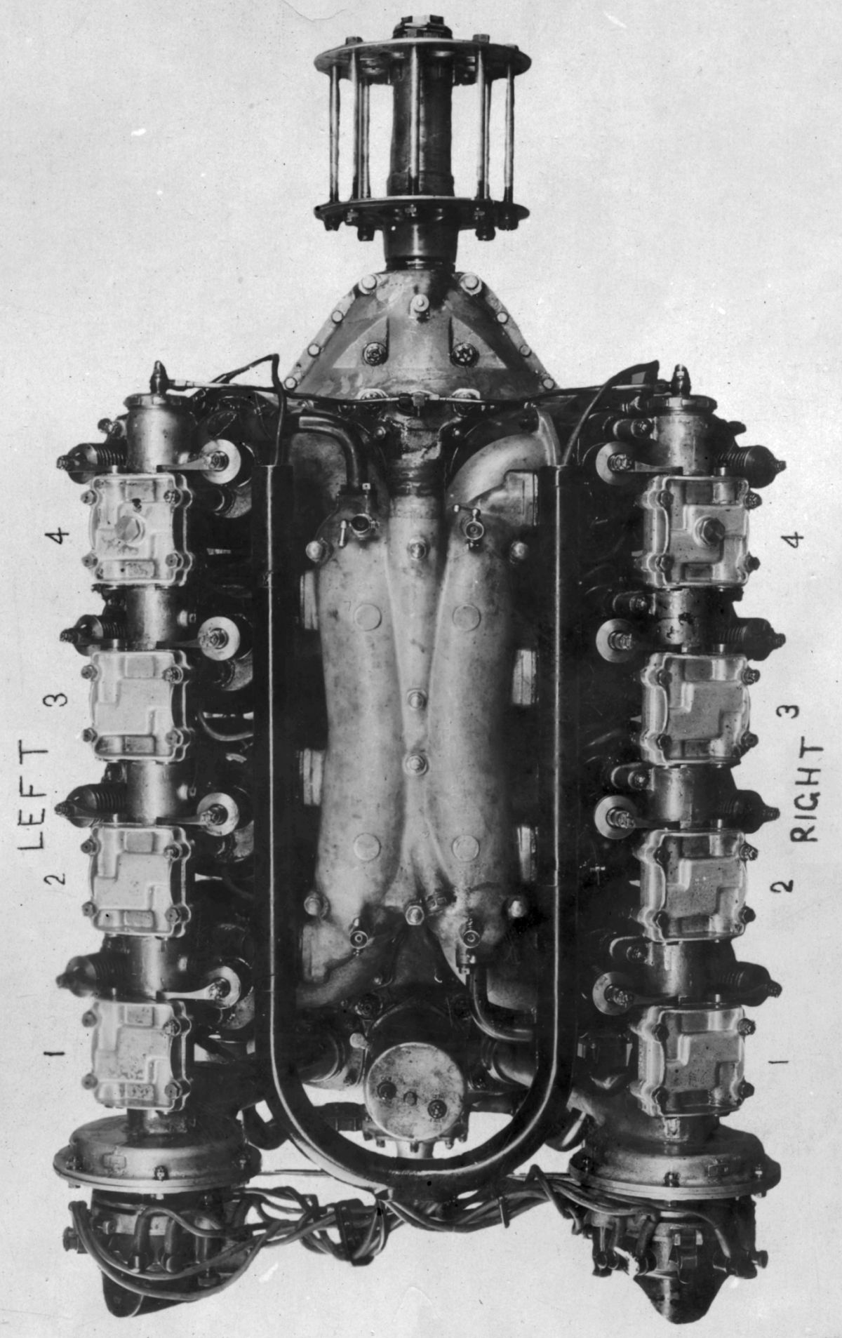
The Lawrance-Moulton Model A, a water-cooled V-8 race car engine, was developed in France and exhibited at the Fifth International Exposition held in Paris during 1913. The Lawrance-Moulton Model B, another 90° V-8 race engine built in the United States during 1916 and 1917, was also adapted to power aircraft. With a 4.750" (120.65 mm) bore, 6.500" (165.10 mm) stroke and 921.47 in³ (15.100 l) displacement, it was rated 200 hp at 1,800 rpm and weighed 876 lb without exhaust manifolds. Available with propeller reduction gear ratios ranging from 3:1 to 3:2, the standard ratio was 2:1. A duplex Zenith carburetor was situated in the Vee. Two eight-cylinder Bosch magnetos provided ignition while running and a battery ignition system was used for starting. A single-impeller centrifugal pump with outlets for each cylinder row circulated cooling water. A gear pump mounted under the oil sump delivered high-pressure oil to the bearings through external pipes. Fork-and-blade connecting rods were used. A 2.4375" clear diameter inlet valve and a 1.75" clear diameter exhaust valve were both lifted 0.625". An auxiliary exhaust consisting of a rotary valve running at one-quarter engine speed opened near bottom center. The inlet valve opened 15.5° late and closed 59.5 late; the exhaust opened 32° early and closed 12° late, the auxiliary exhaust opened and closed 50° each side of bottom center.
 |
 |
| Lawrance A-3 (AEE) | Lawrance N-2 (AEE) |
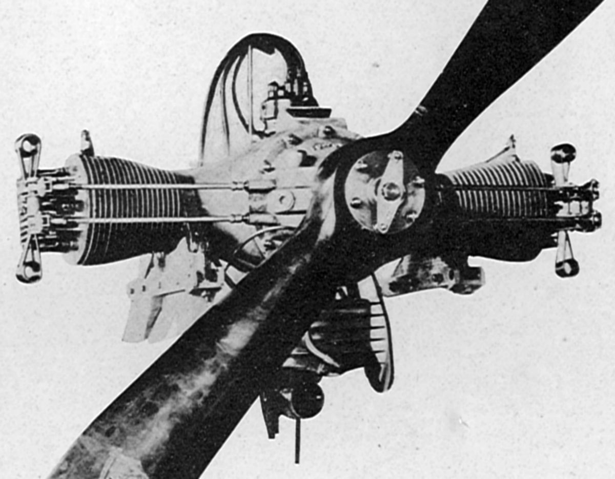
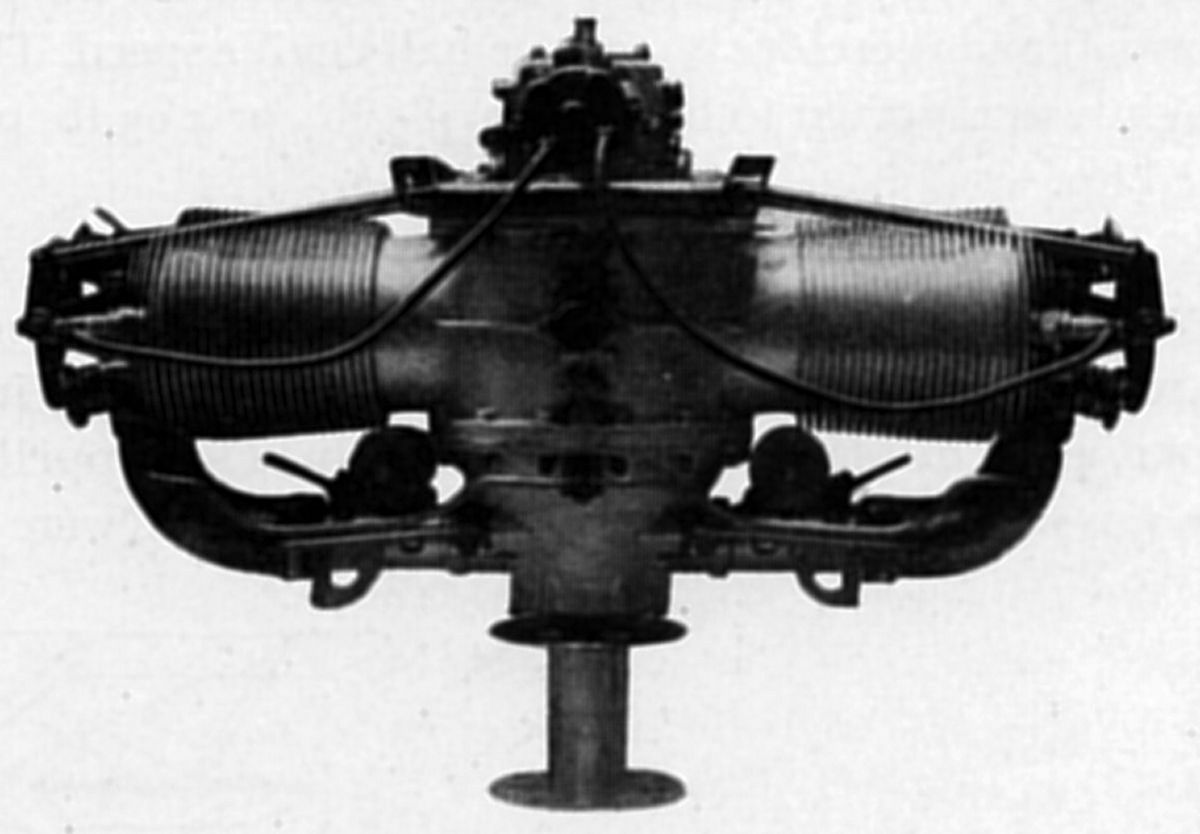
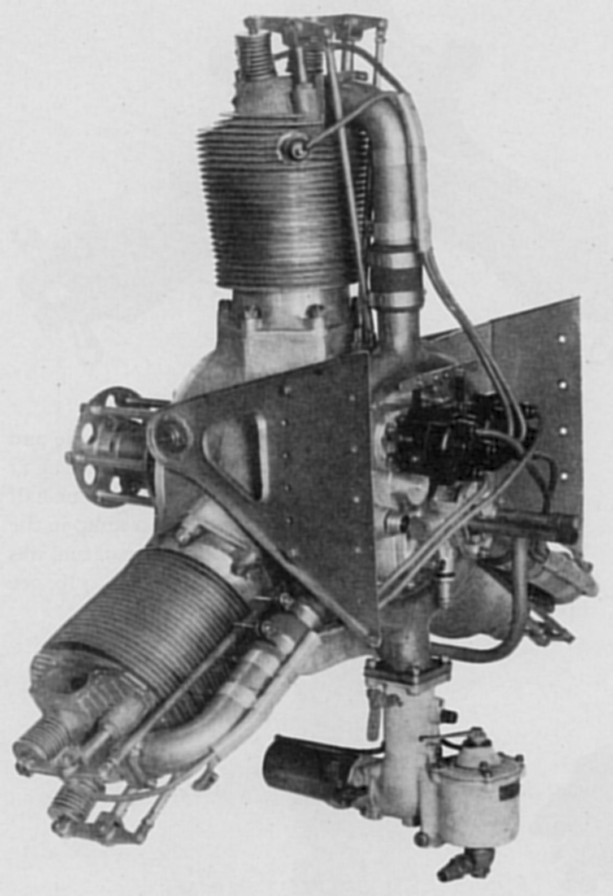
The Model A-3, designed during 1916, was Lawrance's first air-cooled "aircraft" engine. A two-cylinder, horizontally-opposed engine that developed 28 hp at 1,400 rpm, it was used in "Penguin" non-flying training craft. With a 4.000" (101.60 mm) bore, 6.000" (152.40 mm) stroke and 150.80 in³ (2.47 l) displacement, it weighed 148 lb. While this engine had a horizontally-opposed layout, it was not a boxer configuration; rather both connecting rods were side-by-side on the single crankpin. Not only did this arrangement result in uneven firing, but the unbalanced inertia forces caused it to shake like a wet dog. Yet, the hundreds built made their way onto the surplus market after WWI and several schemes converting it into a true boxer configuration for aircraft power appeared during the 1920s and 1930s.
The Model N-2 was an air-cooled two-cylinder horizontally-opposed experimental engine built for the U. S. Navy. With a 4.25" (107.95 mm) bore and stroke and 120.58 in³ (1.976 l) displacement, it was rated 40 hp at 1,900 rpm and weighed 79 lb, or 1.97 lb/hp. Two Zenith horizontal carburetors furnished the mixture and a Philbrin battery system supplied dual ignition. The crankshaft had a single throw and gearing reduced the propeller speed. The valves were interchangeable. The inlet opened 5° early and closed 50° late; the exhaust opened 45° early anti closed 15° late. The N-2 copied all of the A-3's vices, so it was abandoned in favor of the Model L.
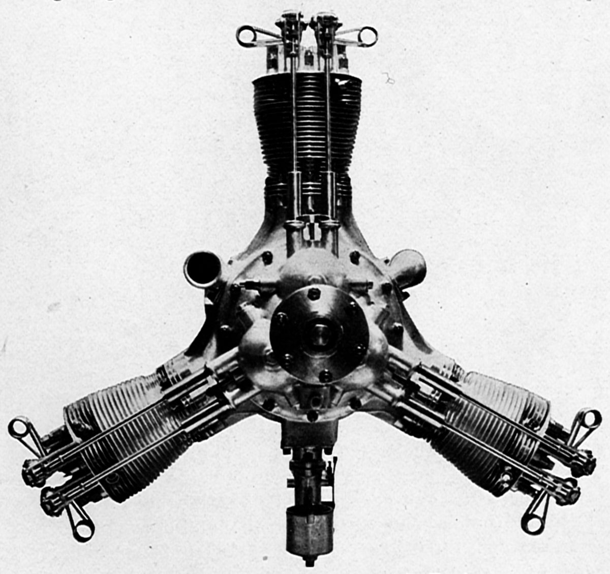
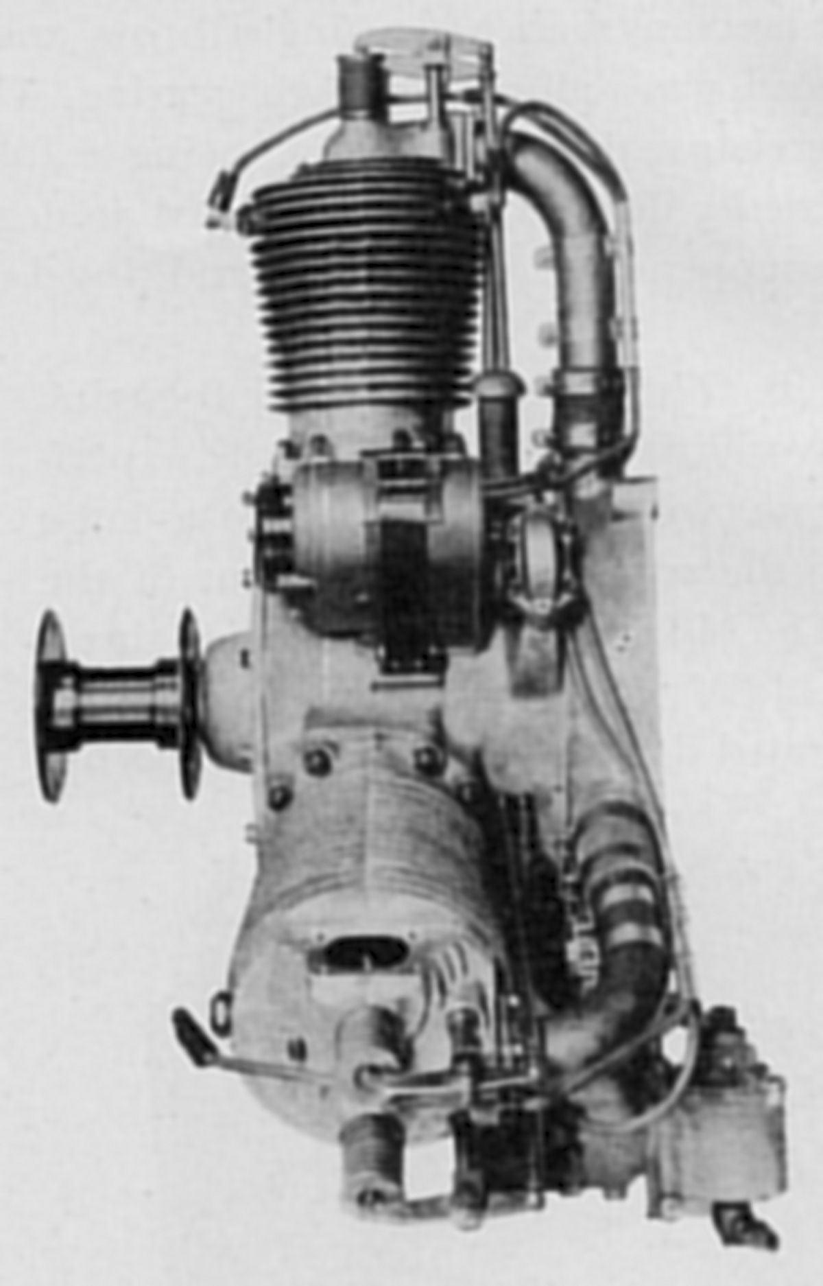
The Lawrance Model B, built as an experimental project in 1916, contributed to the Model L's successful development. The Model B was an air-cooled three-cylinder radial that produced up to 60 hp.
The Model L-2, an air-cooled three-cylinder radial with a 4.250" (107.95 mm) bore, 5.250" (133.35 mm) stroke, 223.43 in³ (3.661 l) displacement, 5.14:1 compression ratio and 125 psi bmep, developed 56.5 hp at 1,600 rpm and weighed 147.4 lb, or 2.6 lb/hp. A Stromberg M-4 carburetor with a 1.312" throat diameter and No. 30 jet furnished the mixture. Oil pressure at 11 psi was maintained by a gear pump running at half engine speed. The oil supply was carried in a lower-crankcase sump. Fuel and oil consumption were 0.512 and 0.04 lb/hp/hr The cylinders, with integral cooling fins, were cast from aluminum alloy and fitted with pressed-in steel liners. The inlet and exhaust valves had 30° seats, 2.00" clear diameters, and 0.470" lift. The inlet opened 42° early and closed 90° late; the exhaust opened 92° early and closed 46° late. The single-throw forged steel crankshaft was fitted with bolt-on counterweights. The slipper-type connecting rods had tubular shanks. The aluminum alloy pistons were fitted with four top compression rings and a lower oil scraper. Battery ignition was employed.
The Lawrance Model L-3 was an improved L-2 where the oil-supply tank was no longer attached to the engine and helical valve springs replaced the volute ribbon type.
The Model L-4 was a later L-series member that became known as the Wright Gale after the Lawrance Aero Engine Corporation was absorbed by the Wright Aeronautical Corporation of Paterson, New Jersey.
The Model L-5 was an L-3 with magnetos replacing battery ignition. Dixie magnetos were mounted radially on the crankcase either side of number one cylinder, the driving end facing aft.
 |
 |
 |
 |
 |
 |
| Model B (AEE) | L-2 (NARA) | L-3 (AEE) | L-5 (AEE) | ||
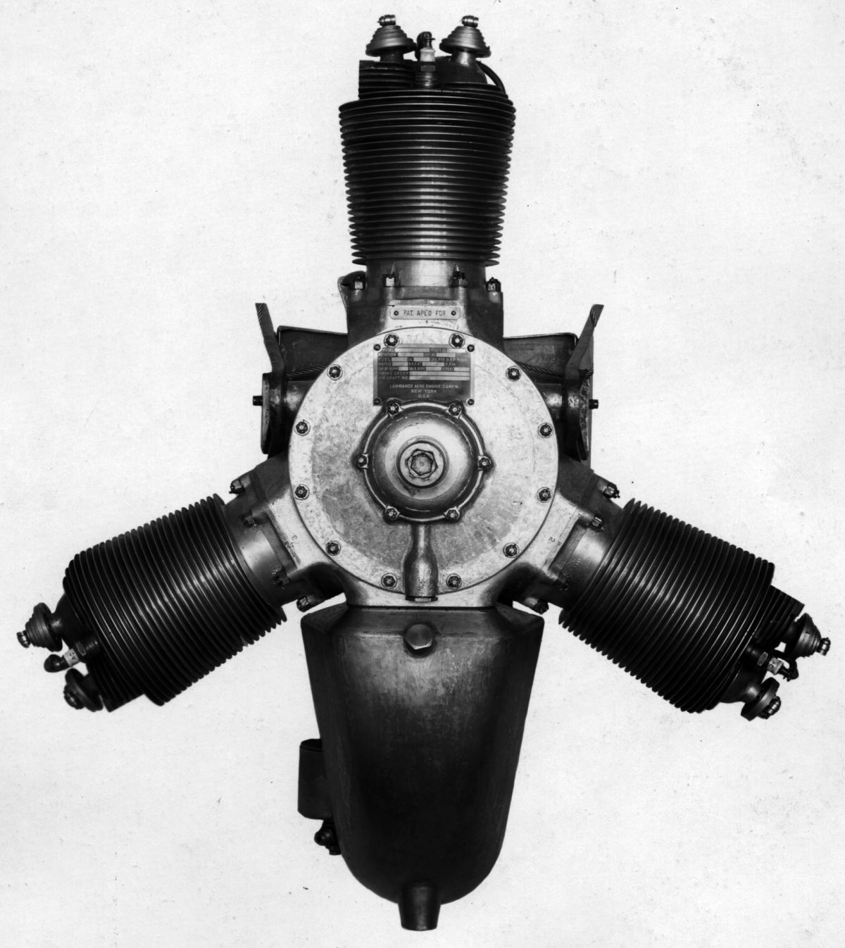
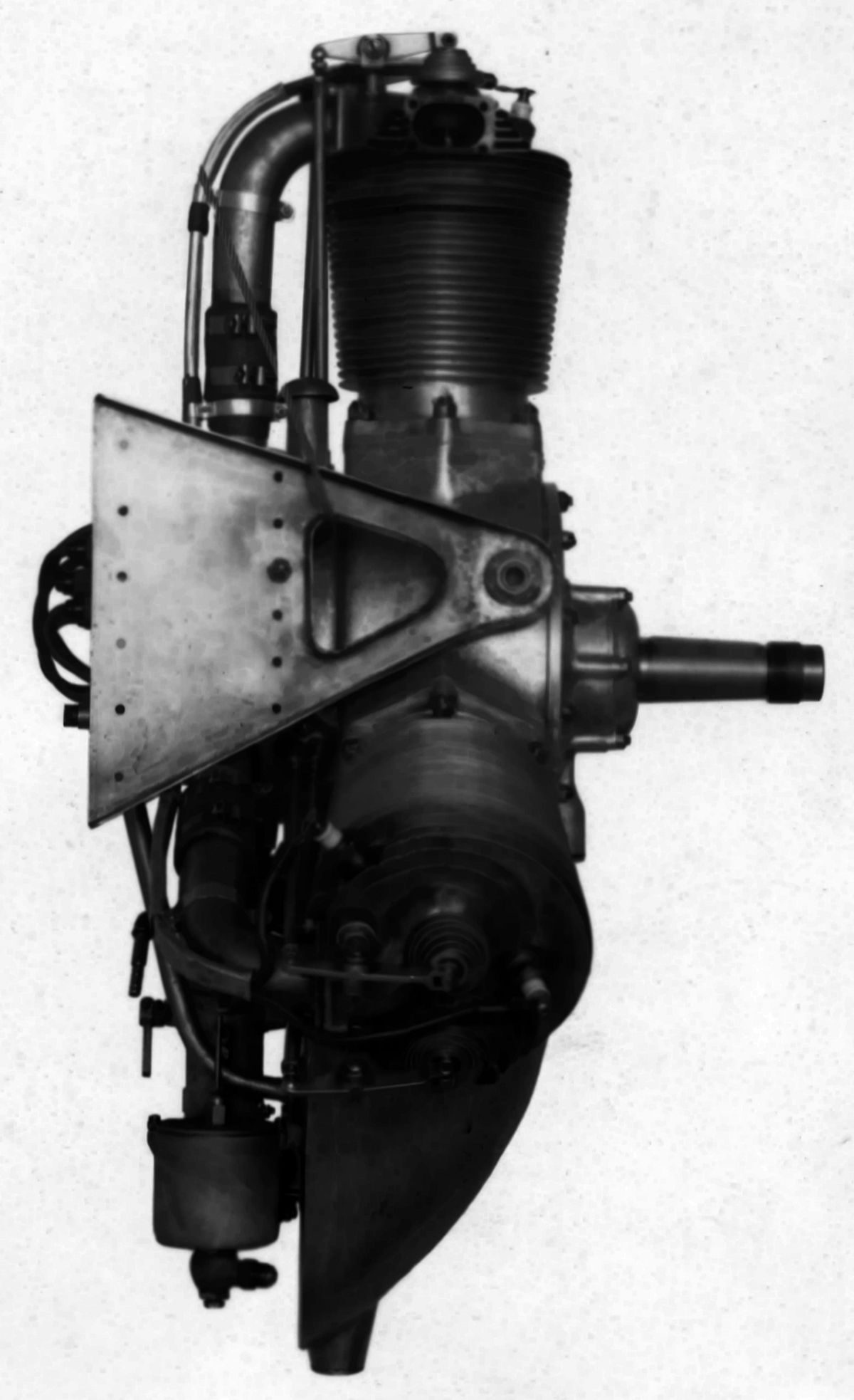
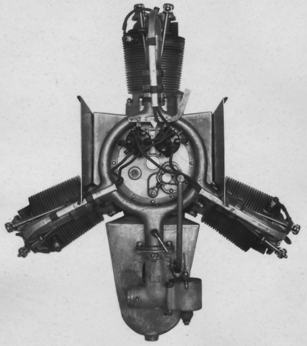
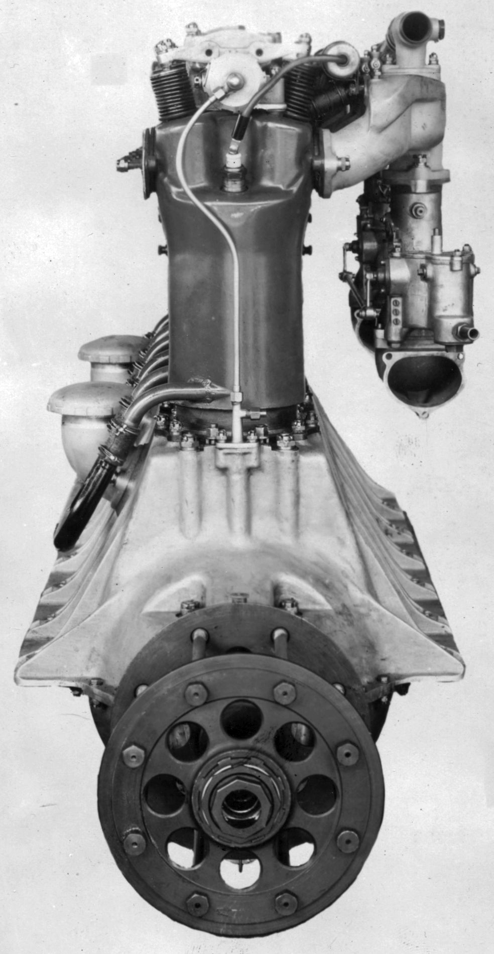
During 1920, following successful Model L tests, Charles Lawrance secured a U.S. Army Air Service contract for a nine-cylinder air-cooled radial using the L-type cylinders that was to develop 140 hp. However, before this contract was completed, the U.S. Navy contracted for a similar nine-cylinder engine having cylinders with a 0.25" larger bore. These engines were developed simultaneously, but after early 1921 acceptance tests the original Air Service project was abandoned. The larger engine became known as the Lawrance J-1 and it completed its first successful fifty-hour test during 1922. Its bore was 4.500" (114.30 mm), its stroke 5.500" (139.70 mm, its displacement 787.26 in³ (12.901 l) and its compression ratio was 5:1. The rated output was 200 hp at 1,800 rpm. On test, it delivered 229.5 hp at 1,750 rpm, and at 131.4 psi bmep with a 5.3:1 compression ratio it produced 240 hp at 1,840 rpm. At normal output fuel consumption was 0.513 lb/hp/hr and oil consumption was 0.021 lb/hp/hr. Dry weight was 476 lb. J-1 cylinders were cast aluminum alloy with integral cooling fins. Bronze spectacle-type valve seats were cast in, and steel cylinder liners were shrunk in place. Some early engines used mercury-cooled valves. The crankshaft was a one-piece forging and a split-master rod connected articulated connecting rods to the crankshaft. The gas mixture was furnished by three Stromberg NA-S4 carburetors, each supplying three evenly-disposed cylinders. Two Splitdorf magnetos mounted crosswise at the engine front provided dual ignition.
 |
 |
| Lawrance J-1 (AEE) | |
Following completion of Government Model J-1 contracts, the Lawrence company merged with the Wright Aeronautical Corporation and the development of this series continued under the leadership of Charles L. Lawrance, who later became president.
However, before this change occurred, two experimental J-2 engine models were built. These were similar to the J-1 except that the cylinders had a 4.875" bore and there were other minor modifications. The development was not continued, however, as it was considered that the J-1's displacement was sufficient for the purpose intended.
Le Rhône
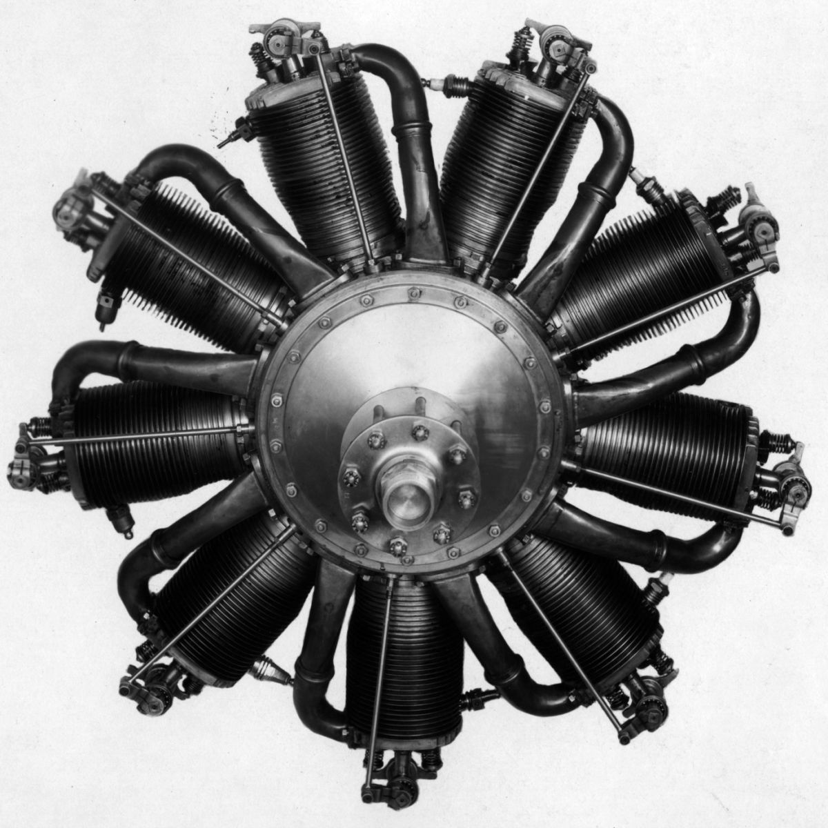
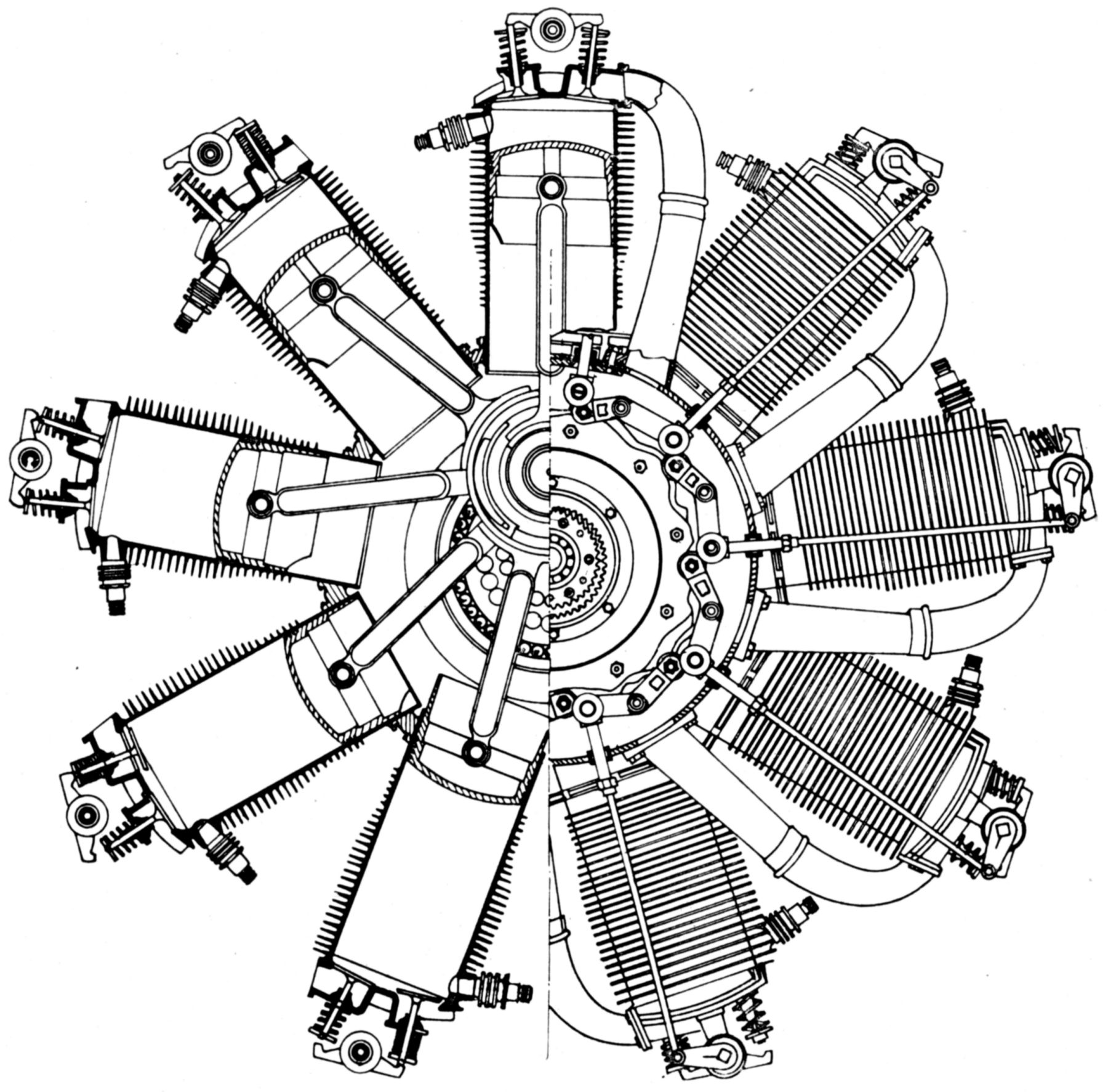
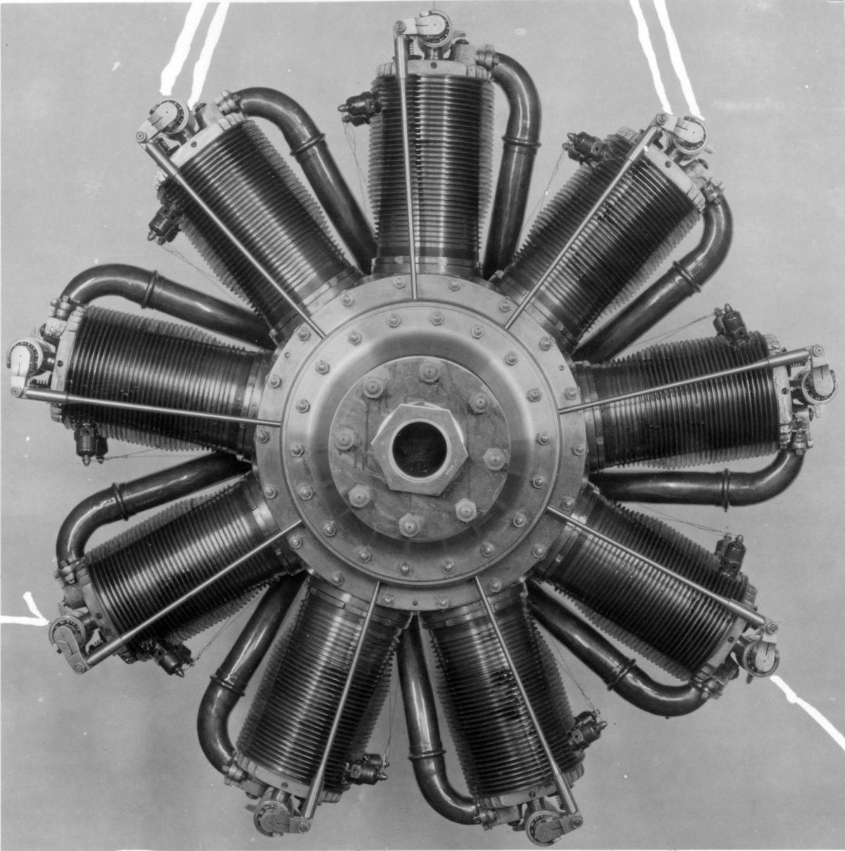
Le Rhône air-cooled rotary engines were built by the Société des Moteurs Gnôme et Rhône, 41 Rue La Boétie, Paris, France and by The Gnome and Le Rhône Engine Co., 47 Victoria Street, Westminster, London, S. W. England. The Type 9C 80-hp engine also was produced in America during 1917-18 by the Union Switch and Signal Company of Swissvale, Pennsylvania.
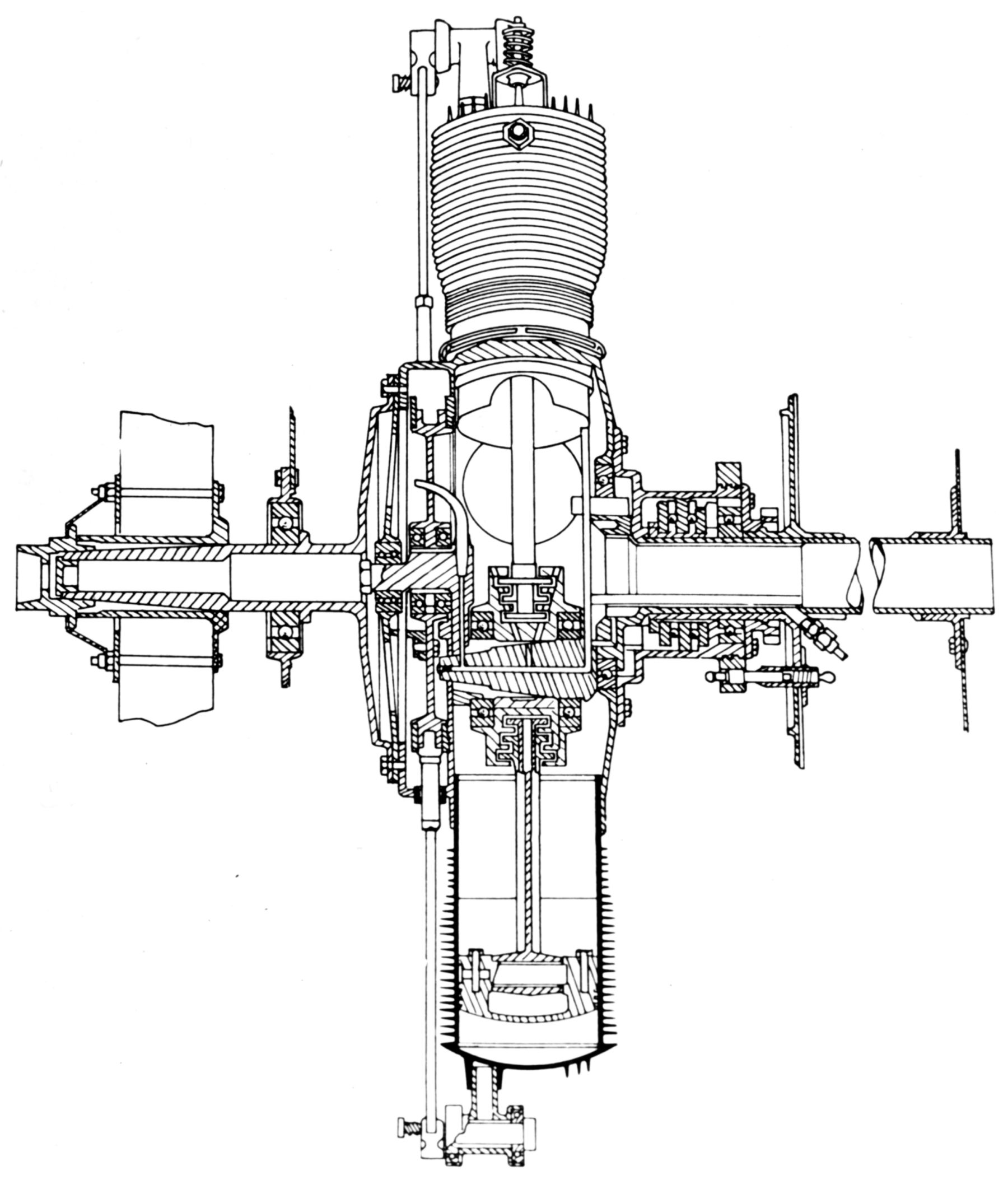
Le Rhône engine cylinders were machined, with integral cooling fins, from steel forgings, and then fitted with cast-iron liners. The cylinder lower ends screwed into the steel crankcase and were secured by lock rings. Single inlet and exhaust valves in each cylinder head were operated by a single valve rod and oscillating rocker arm that was supported on ball bearings. The valve springs held the valves closed only while starting as centrifugal force kept them seated while running. Le Rhône pistons were generally made from cast-iron and fitted with special tungsten-steel rings.
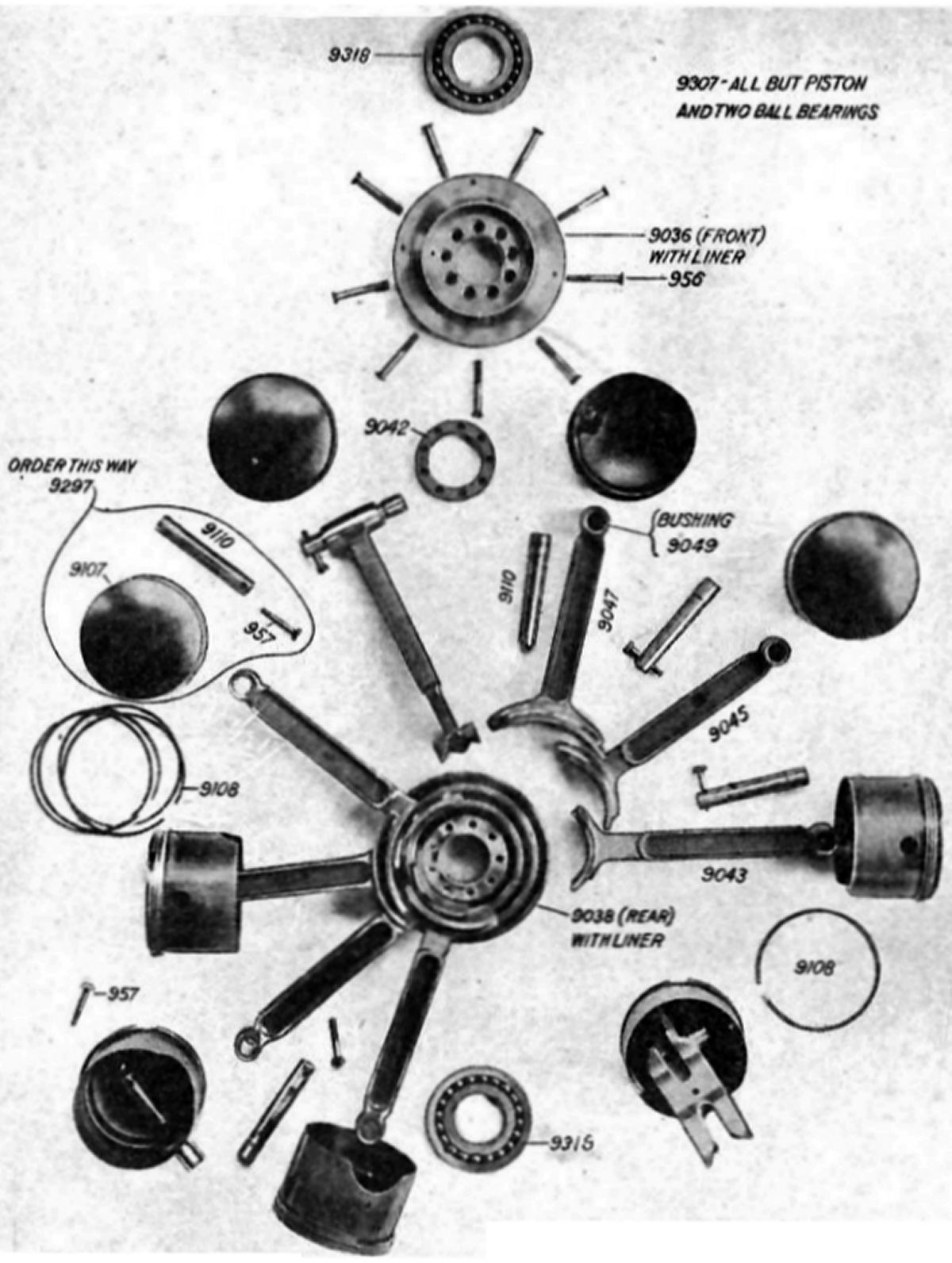
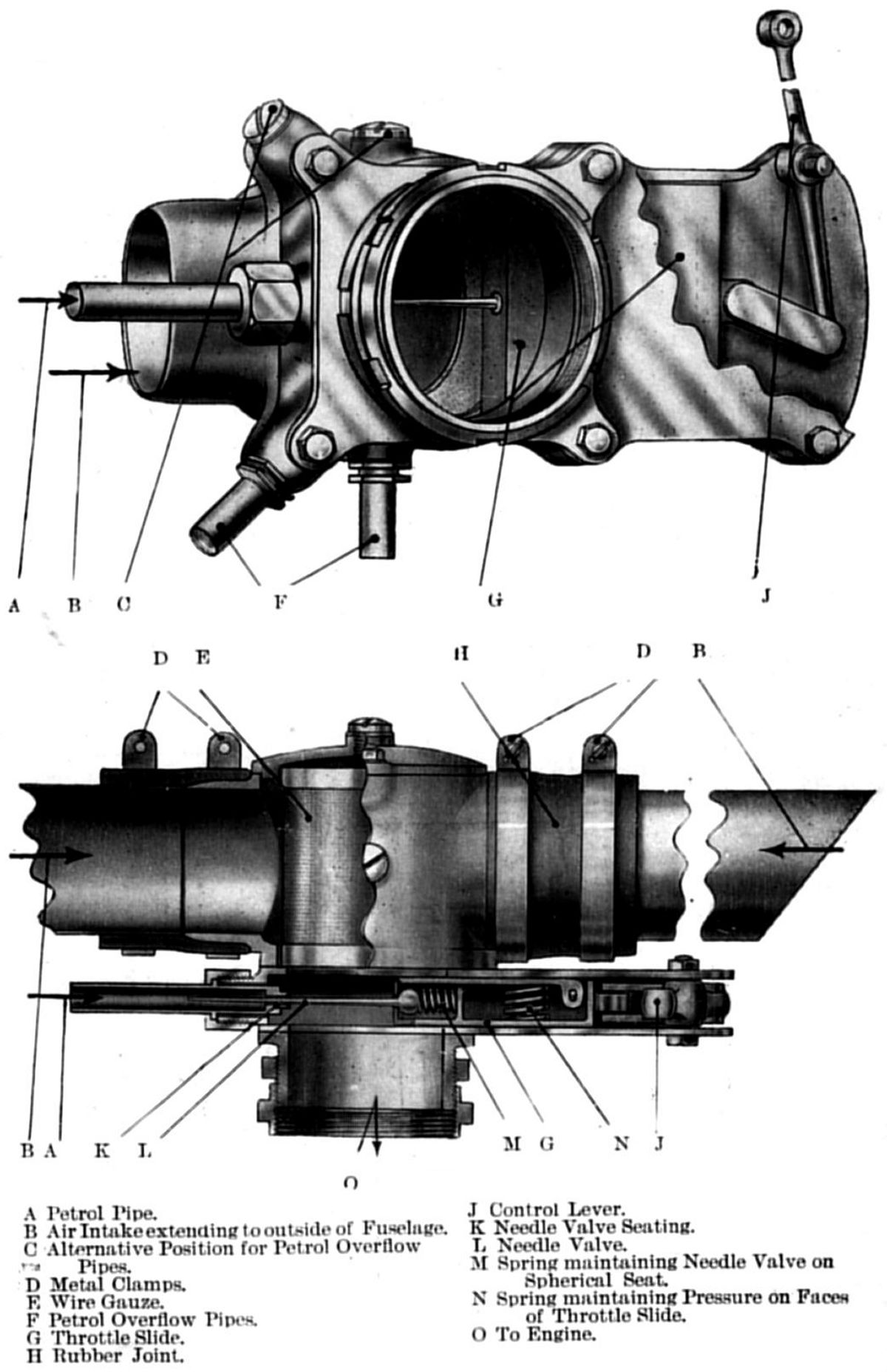
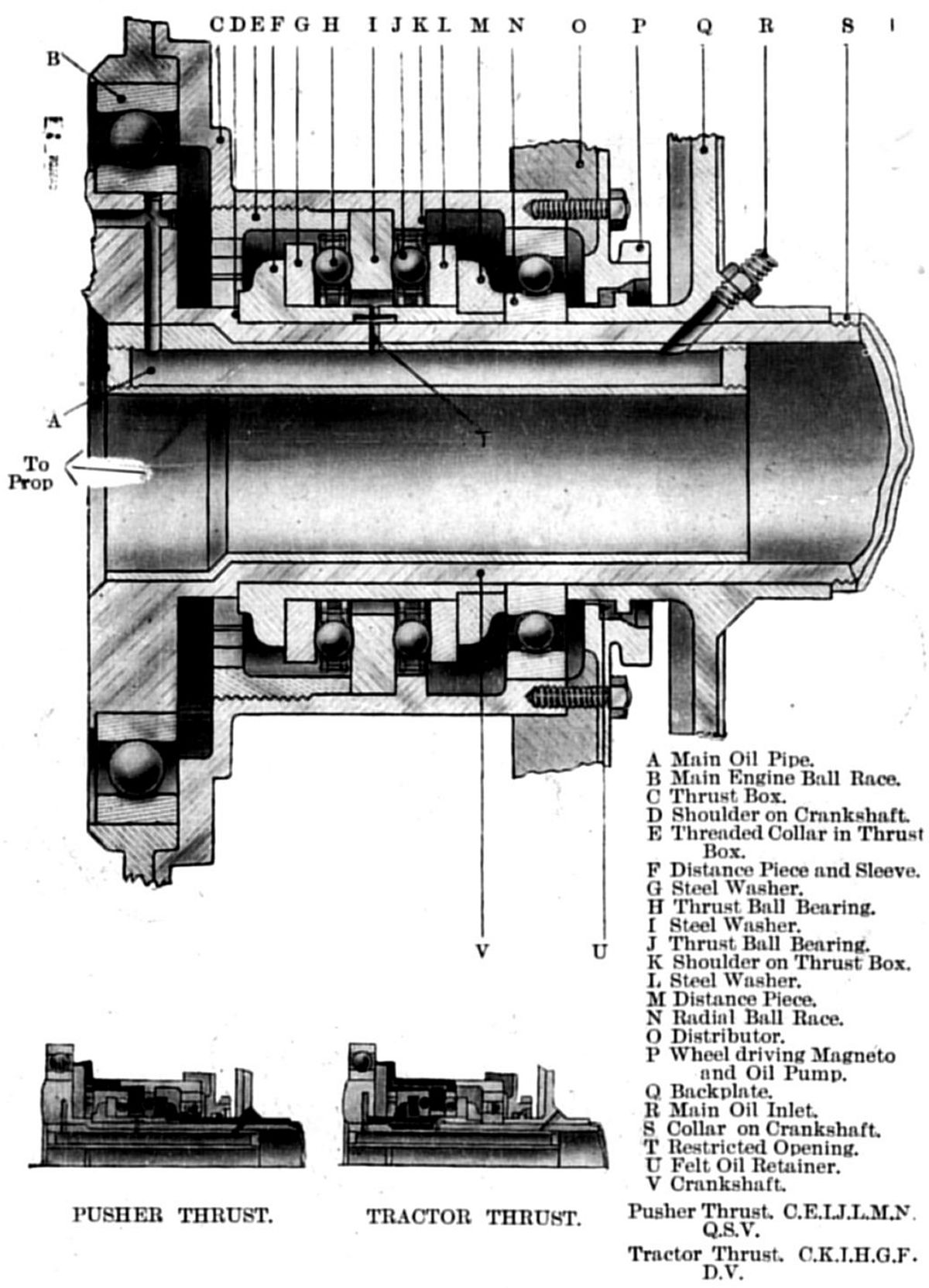
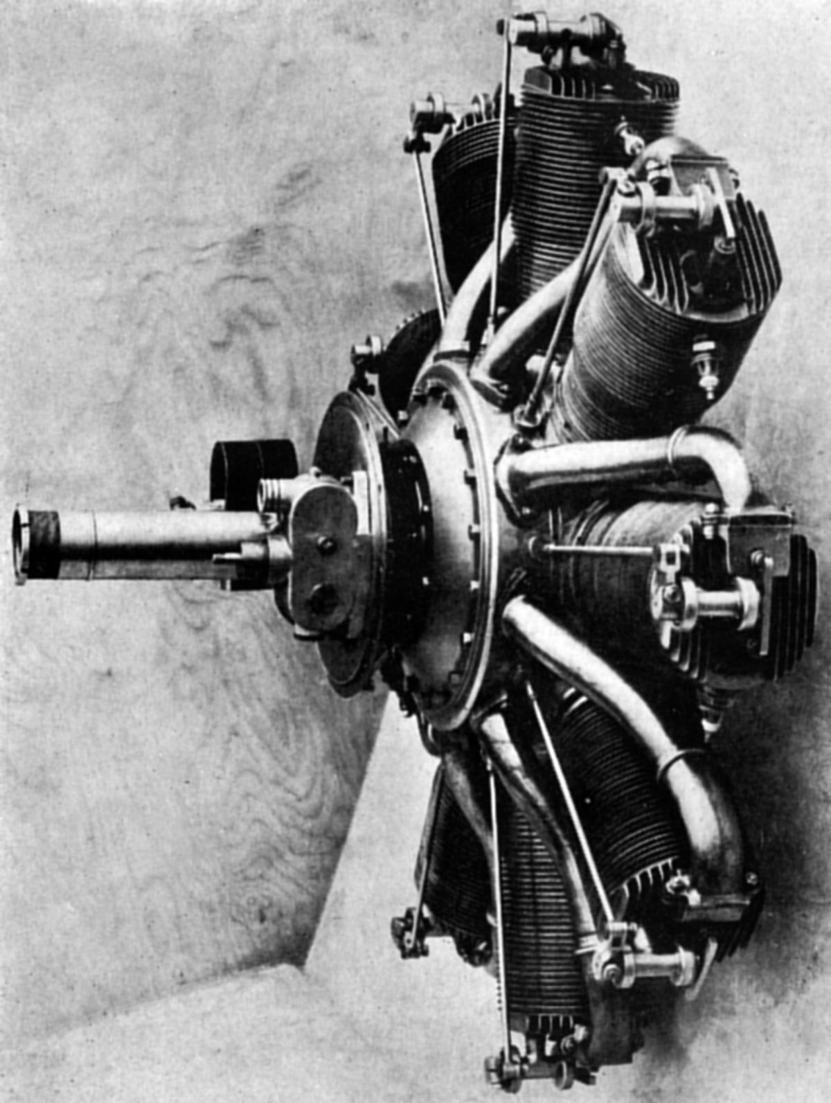
The propeller hub was integral with the steel front crankcase cover. The fixed built-up crankshaft supported the crankcase and connecting rod assemblies on ball bearings, including a double-row ball thrust bearing near the engine rear. The slipper-type connecting rods had H-section shanks. The fuel/air mixture entered a distribution chamber through the fixed hollow crankshaft from a rear-mounted carburetor and was then led to the cylinders by centrifugal force through copper inlet pipes.
 |
 |
 |
 |
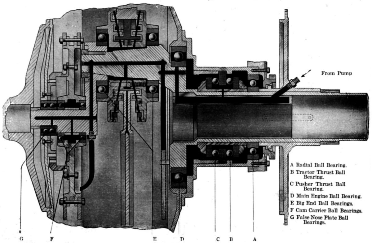 |
| Rods, Pistons (LeR) | Cams (LeR) | Carburetor (LeR) | Thrust Bearing (LeR) | Lubrication (LeR) |
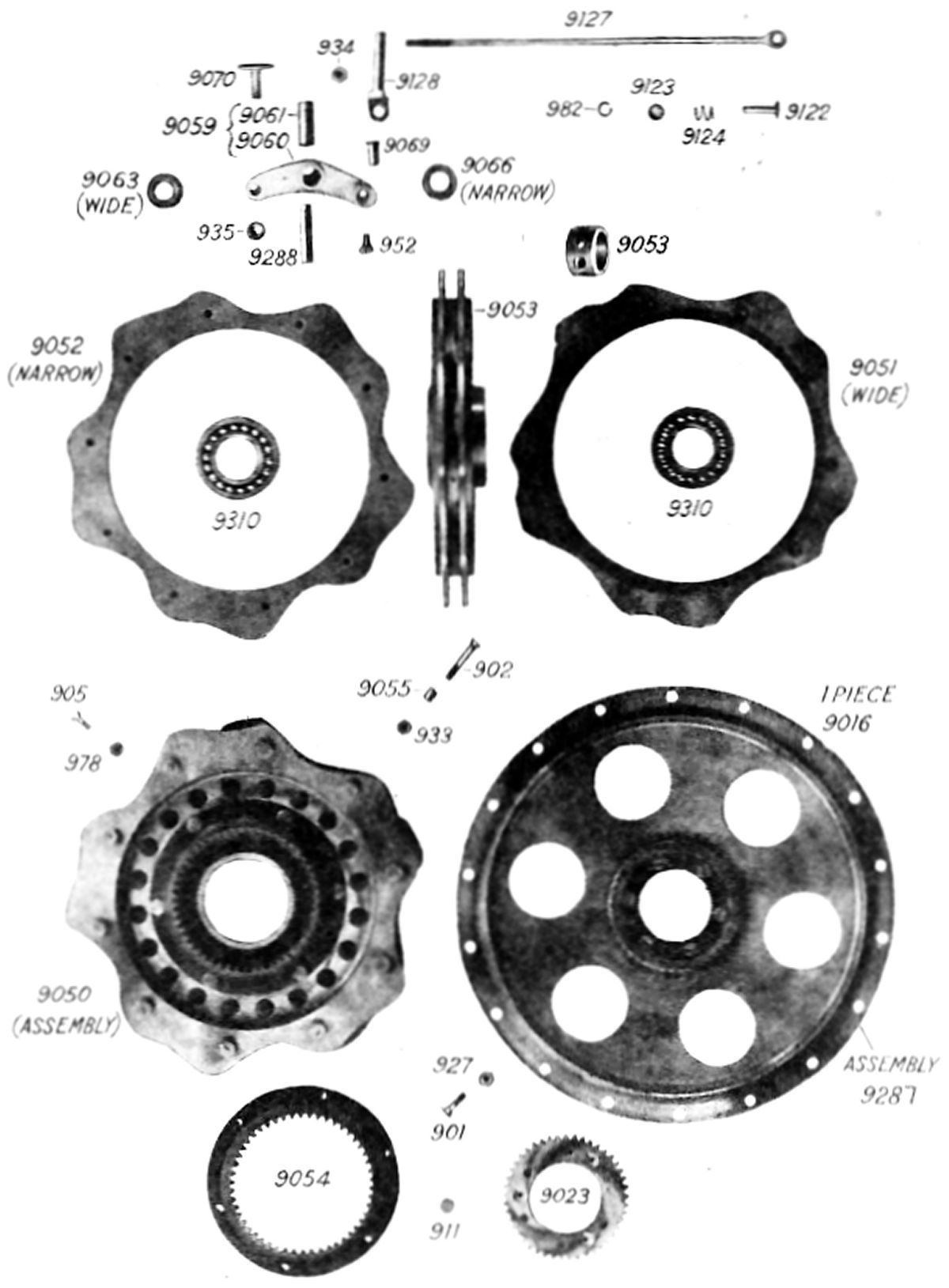
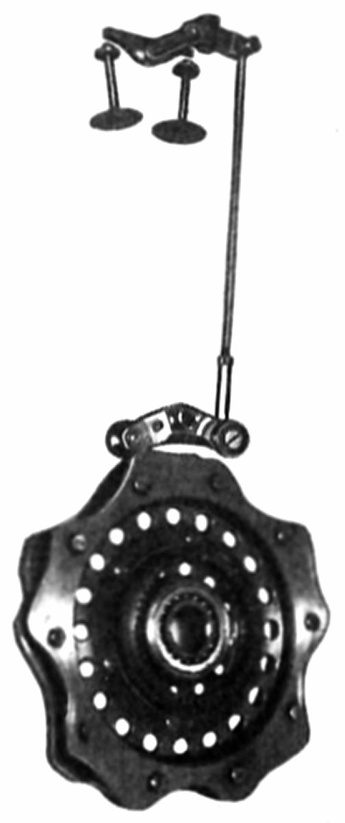
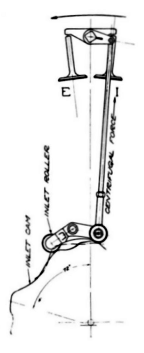
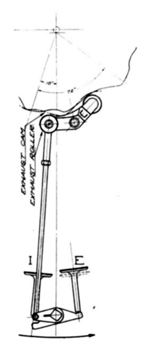
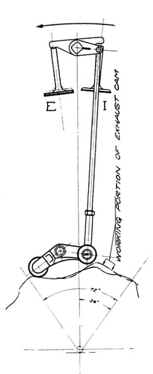
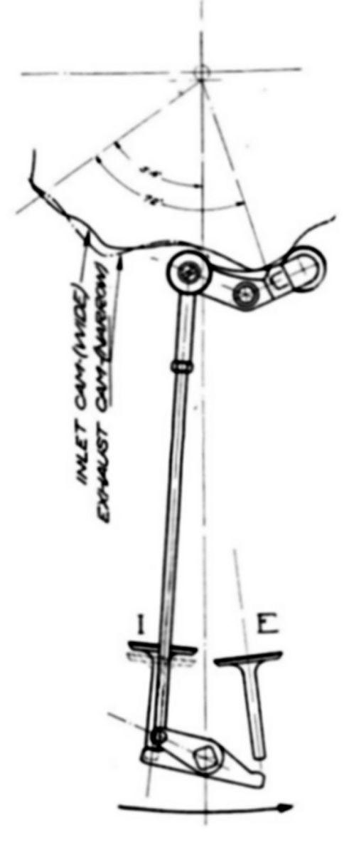
The valve mechanism consisted of an inlet cam ring joined to an exhaust cam ring, the assembly operating a cam rocker connected to each valve rod. The cam rocker received an oscillating motion through contact with the cam rollers on their respective cams. The cam profile was repeated Y/2 +1 times, where Y is the number of cylinders. The cam assembly rotated in the same direction as engine rotation at 1/(Y+1) times engine speed. The cam assembly ran on ball bearings mounted to an eccentric crankshaft journal and timed by internally meshed gears. Centrifugal force held the inlet cam roller hard against its cam.
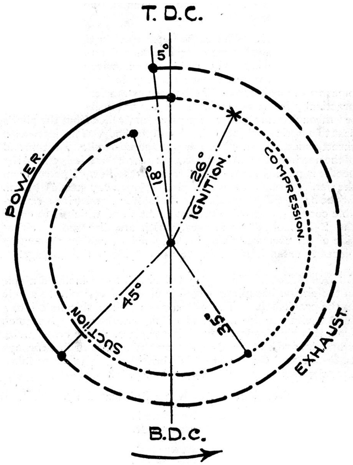
The 9-cylinder Le Rhône 9C serves as a valve operation example. Please see Figure 1. Cam ring movement relative to the cylinders controlled valve action. Centrifugal force on the valve rod actuated the valves and held the inlet roller against the inlet cam. The five-lobed inlet cam profile represents five complete valve actuation cycles (four strokes per cycle) or ten engine revolutions. Therefore, the cam must move 1/10 revolution relative to the roller for each cylinder's revolution around the crankshaft. Le Rhône engine cams were geared to revolve in the same direction as the cylinders, but at 9/10 cylinder speed. Thus the cam dropped back 1/10 revolution or 36° for each engine revolution. Figure 2 shows the positions of cam, rocker, and valves at power stroke top center. Both valves are closed and the inlet roller is held against the inlet cam by centrifugal force on the valve rod. It is in this position that valve stem clearances are measured. The next half cylinder revolution ended the power stroke (Fig. 3); the cam moved 18° less than the cylinder and 18° relative to the cam rocker. The complete inlet, compression, power, and exhaust cycle repeats every 72° on the cam. The inlet roller bears upon the inlet cam except when the exhaust opens and a positive outward exhaust cam push opens the exhaust valve against cylinder pressure. The exhaust valve opened when the exhaust cam pushed outward on the exhaust roller, about 50° ahead of bottom center. At this point cylinder pressure acting on the exhaust valve had diminished and centrifugal force again held the inlet roller in contact with the inlet cam. The point of exhaust valve opening is on the exhaust cam, while the maximum opening of exhaust valve and the point at which it closes are determined by the inlet cam contour. All inlet valve operations are controlled by the inlet cam. Figure 14 shows the cylinder one half revolution after Figure 13. The cam has moved 1/20 revolution or 18° in relation to the cylinder. The exhaust valve was held open by centrifugal force acting on the valve rod, but is nearing the closing point. Another half revolution (now 540° total) ended the intake stroke (Fig. 15). The inlet valve was held open by the cam and is within 40° of its closing point. Another half revolution completed the four-stroke cycle, bringing the valve action back to the position shown in Figure 12, but on the next cam segment. The inlet roller moved 72° around the cam. Each operation described here was repeated every 72° of the cam rotation. The engine made 10 complete revolutions to bring the cam back to its original position, and in the meantime each cylinder goes through its operating cycle 5 times.
 |
 |
 |
 |
 |
| Fig. 1 | Fig. 2 | Fig. 3 | Fig. 4 | Fig. 5 |
Le Rhône Type 7A air-cooled 7-cylinder rotaries were introduced in 1910. With a 105 mm (4.134") bore, 140 mm (5.512") stroke and 8.486 l (517.85 in³) displacement, it was rated 50 hp at 1,200 rpm. The Type 7B, rated 50 hp at 1,300 rpm followed in 1911. The 1912 Type 7B2 was rated 60 hp at 1,200 rpm. All had the same displacement and weighed 88 kg (194 lb).
 |
 |
 |
 |
| Le Rhône Front, Sections, Valve Timing (NARA, A39) | |||
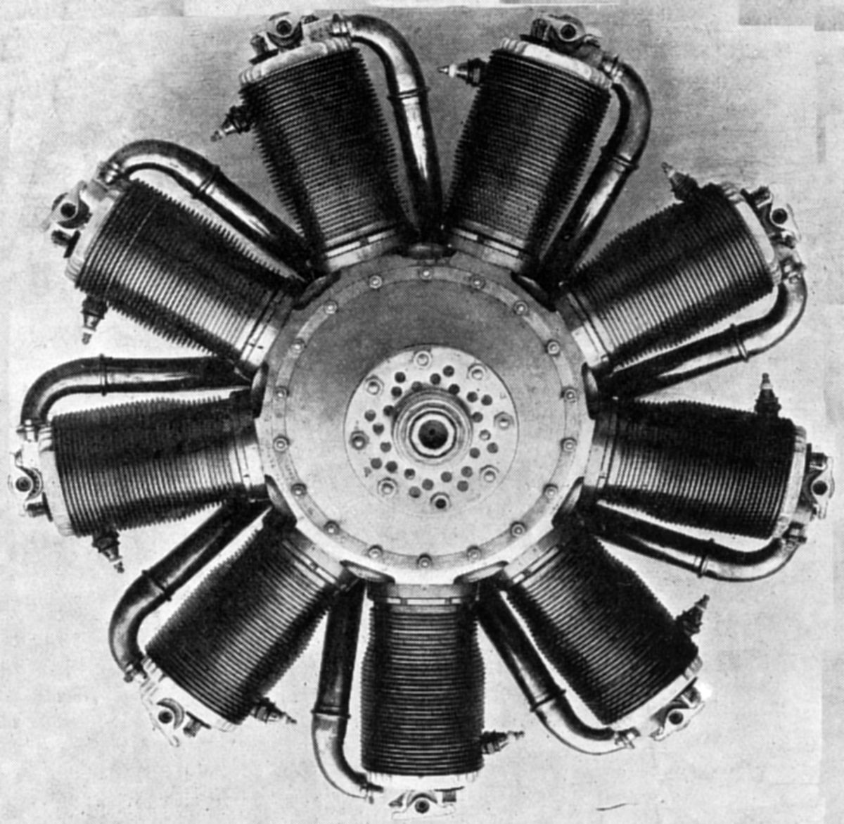
The Type 9C, also introduced in 1912, used the same 105 x 140 mm bore and stroke as the Type 7, but with 9 cylinders displaced 10.91 l (665.77 in³). With its 4.8:1 compression ratio, it was rated 80 hp at 1,200 rpm and weighed 116 kg (256 lb). Fuel and oil consumptions were 0.57 and 0.094 lb/hp/hr. Valve diameters were 46 mm (1.811") and their seats were cut at 36.5°. The inlet valves opened 18° late and closed 34° late; the exhaust valves opened 38° early and closed 6° late.
 |
 |
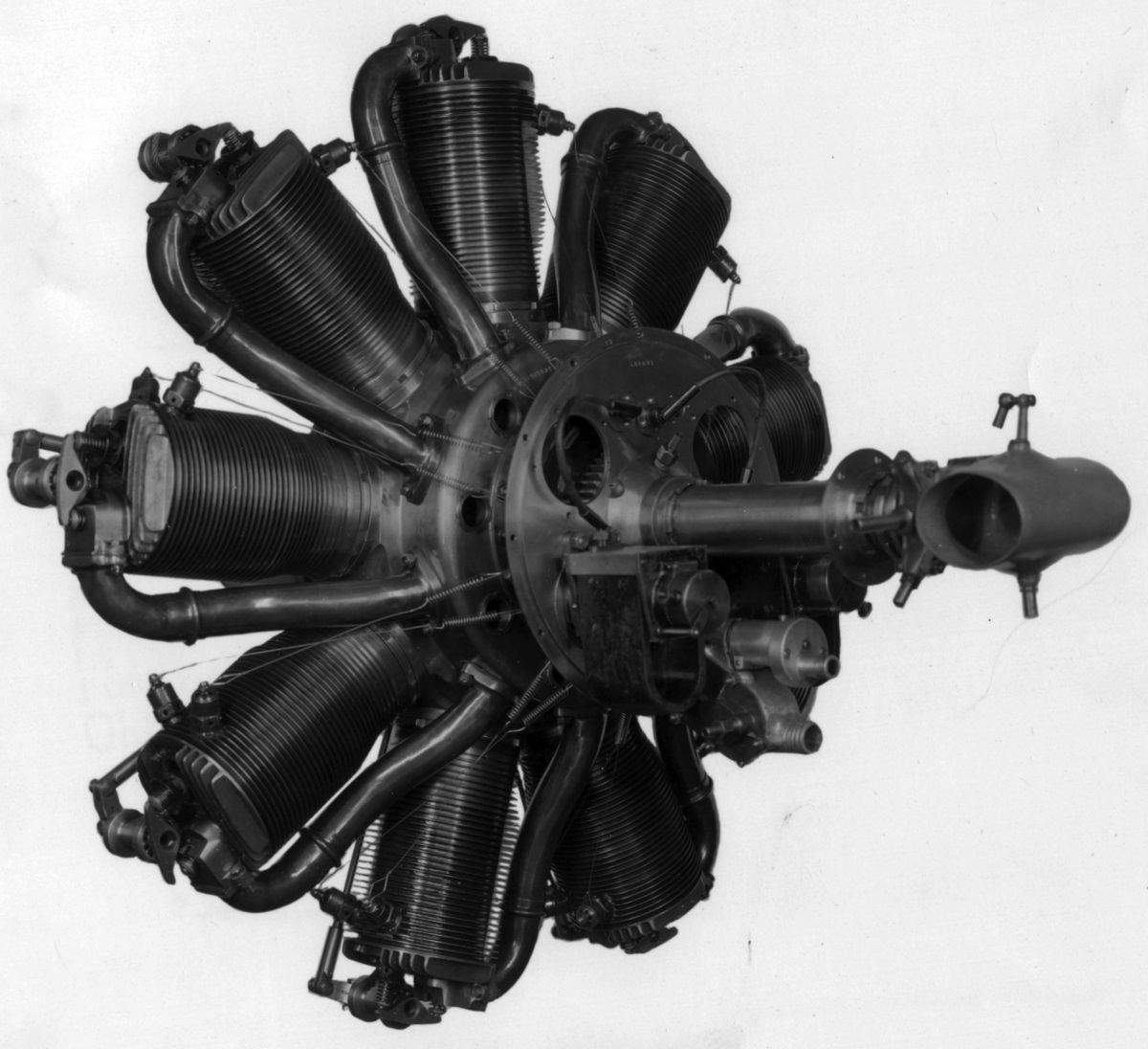
| Le Rhône 9J (NARA) | |
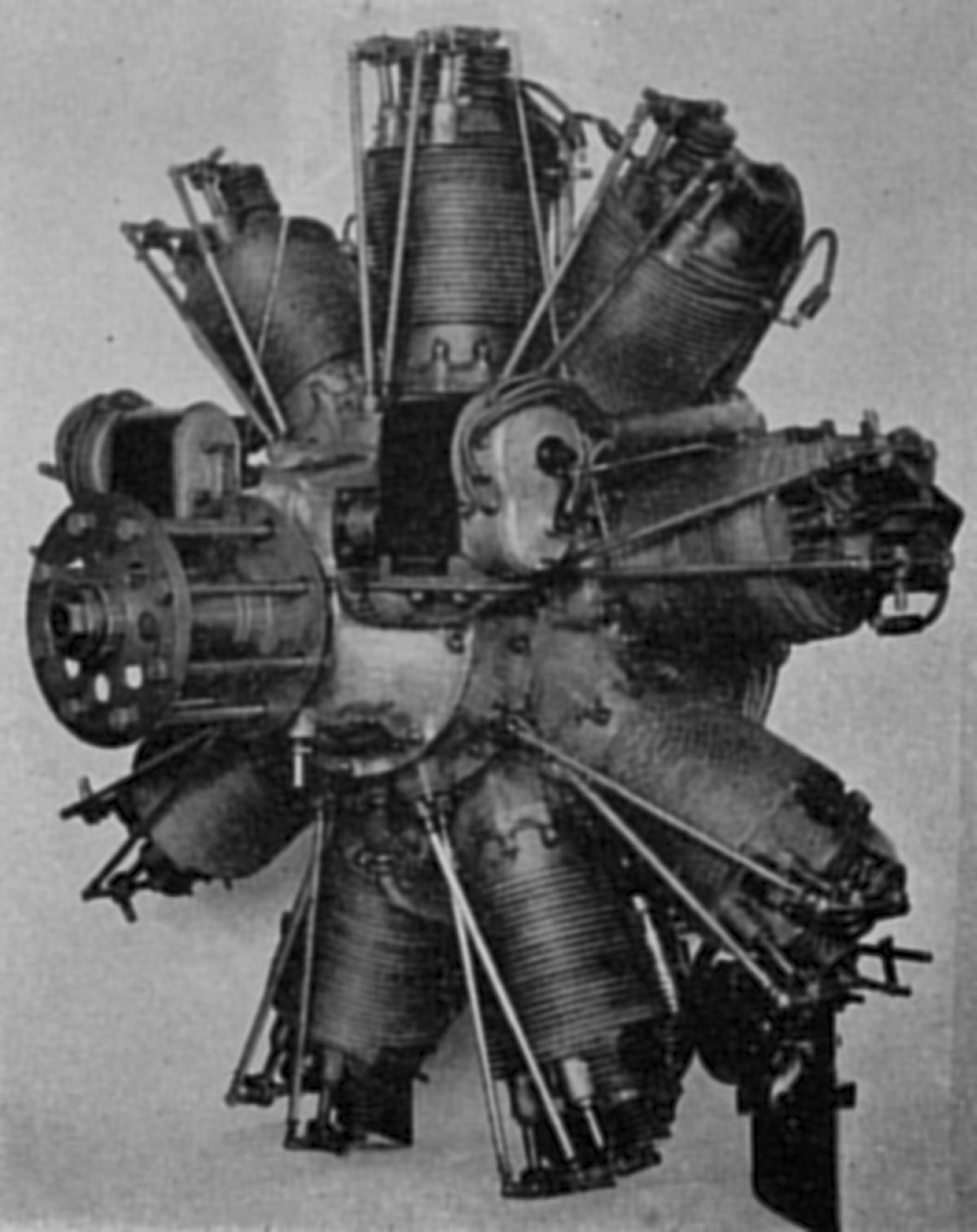
The 1913 Type 9J had a 112 mm (4.409") bore, 170 mm (6.693") stroke, 15.074 l (919.87 in³) displacement and 5.0:1 compression ratio. It was rated 110 hp at 1,200 rpm and weighed 137 kg (302 lb). Fuel and oil consumptions were 0.69 and 0.1 lb/hp/hr. The cam mechanism was located aft. Inlet and exhaust valves had 45 mm (1.772") clear diameters and 10.5 mm (0.413") lift. Inlet valves opened and closed 30° late; exhaust valves opened 40° early and closed 16° late. Over 9,350 Type 9Js were produced.
In 1915, the Type 9Ja was introduced. It had the same dimensions and performance as the Type 9J, but was 5 kg (11 lb) lighter, at 132 kg (291 lb). The Type 9Jb and Type 9Jby followed in 1916, with the same dimensions, but with 120 hp at 1,250 rpm and 130 hp at 1,350 rpm. Weight for both was still 132 kg (291 lb).
The Le Rhône Type L and Type K air-cooled 9-cylinder rotary prototypes also appeared in 1916. These produced 200 hp at 1,300 rpm, but it is unclear whether they were ever produced. In 1917, the Le Rhône Type P, an air-cooled 9-cylinder 120 hp rotary appeared. Later in 1917, the Le Rhône Type M 9-cylinder rotary with a 135 mm (5.315") bore, 210 mm (8.268") stroke and 27.053 l (1650.89 in³) displacement producing 200 hp at 1,300 rpm and weighing 240 kg (529.11 lb) was introduced.
 |
 |
| Le Rhône 9R (NARA) | |
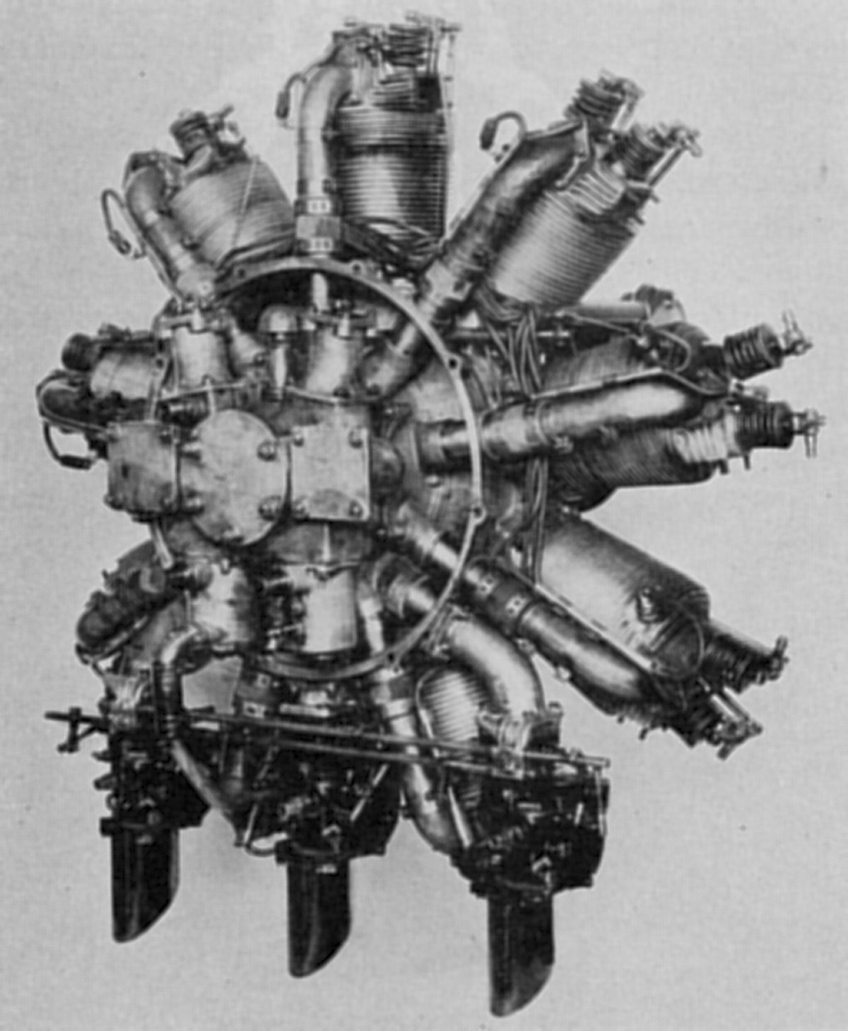
The 1917 Le Rhône Type R with a 115 mm (4.528") bore, 170 mm (6.693") stroke 15.892 l (969.79 in³) displacement and 5.65:1 compression ratio produced 170 hp at 1,360 rpm and weighed 166 kg (366 lb). Inlet valve diameter was 52 mm (2.047"), exhaust valve diameter was 50 mm (1,969") and lift for both was 11 mm (0.433"). The inlet valves opened 20° late and closed 40° late; the exhaust opened 60° early and closed 15° late. Fuel and oil consumptions were 0.65 and 0.093 lb/hp/hr. The Type R introduced several new features, including high compression, aluminum pistons, a new induction system with distribution channels closer to the carburetor, a crankcase cooling scheme and dual ignition. Its diameter was 1,007 mm (39.65") and its length was 1,005 mm (39.57").
 |
| 11F (NARA) |
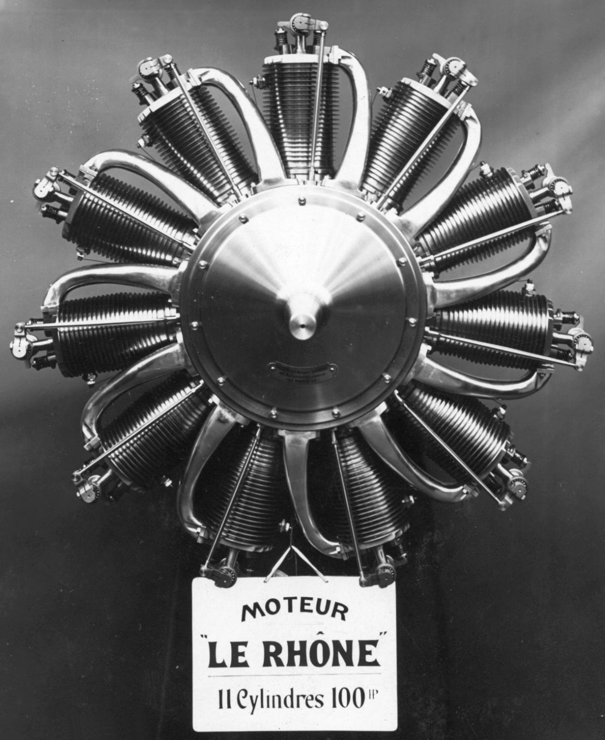
In 1913, the Le Rhône Type 11F, an air-cooled 11-cylinder rotary was introduced with a 105 mm (4.134") bore, 140 mm (5.512") stroke and 10.91 l (665.77 in³) displacement. It was rated 100 hp at 1,200 rpm and weighed 120 kg (265 lb).
Le Rhône parleyed its single-row rotary collection into several multi-row engines. In 1912, Le Rhône introduced the Type 14D, which was essentially two 7B2s in tandem on a two-throw, 180° crankshaft. This engine displaced 16.972 l (1,035.70 in³) and was rated 120 hp at 1,150 rpm; it weighed 170 kg (375 lb).
The Type 18E, a doubled Type 9C that appeared in 1912 and displaced 21.821 l (1,331.6 in³), was rated 160 hp at 1,150 rpm and weighed 210 kg (463 lb). A later 1917 prototype, a doubled Type 9R, had a 115 mm (4.528") bore, 170 mm (6.693") stroke and 31.784 l (1,939.6 in³) displacement was rated 340 hp at 1,200 rpm and weighed 300 kg (661 lb).
The 1918 prototype Type 28E had four 7-cylinder rows of cylinders with 115 mm (4.528") bores, 140 mm (5.512") strokes, displaced 40.717 l (2,484.7 in³). It was rated 320 hp at 1,300 rpm and weighed 300 kg (661 lb).
In 1920, Le Rhône debuted its Model Z series for general aviation light airplanes. The Type 7Z, an air-cooled 7-cylinder rotary with an 85 mm (3.347") bore, 105 mm (4.134") stroke and 4.171 l (254.53 in³) displacement developed 40 hp at 1,300 rpm and 63 hp at 1,450 rpm. Fuel and oil consumptions were 0.518 and 0.110 lb/hp/hr. Weight was 65 kg (144 lb).
The Type 9Z, an air-cooled 9-cylinder rotary with an 84 mm (3.307") bore, 106 mm (4.173") stroke and 5.287 l (322.63 in³) displacement developed 60 hp at 1,450 rpm and weighed 68 kg (150 lb).
Liberty
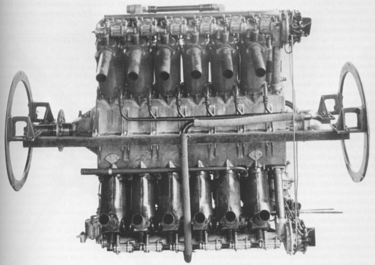
 |
 |
 |
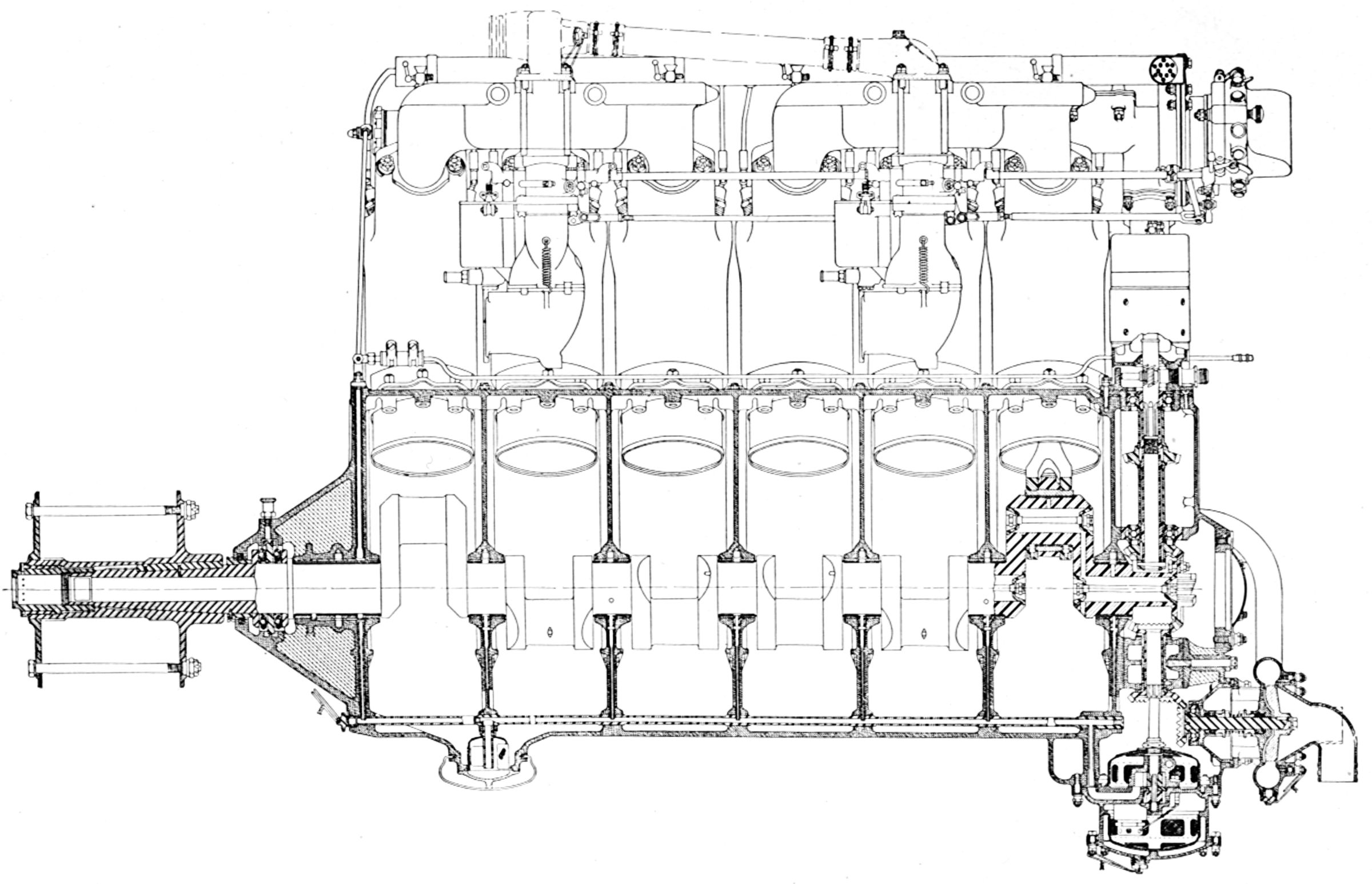
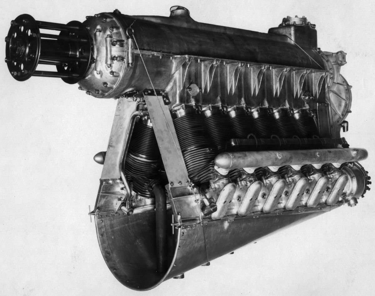
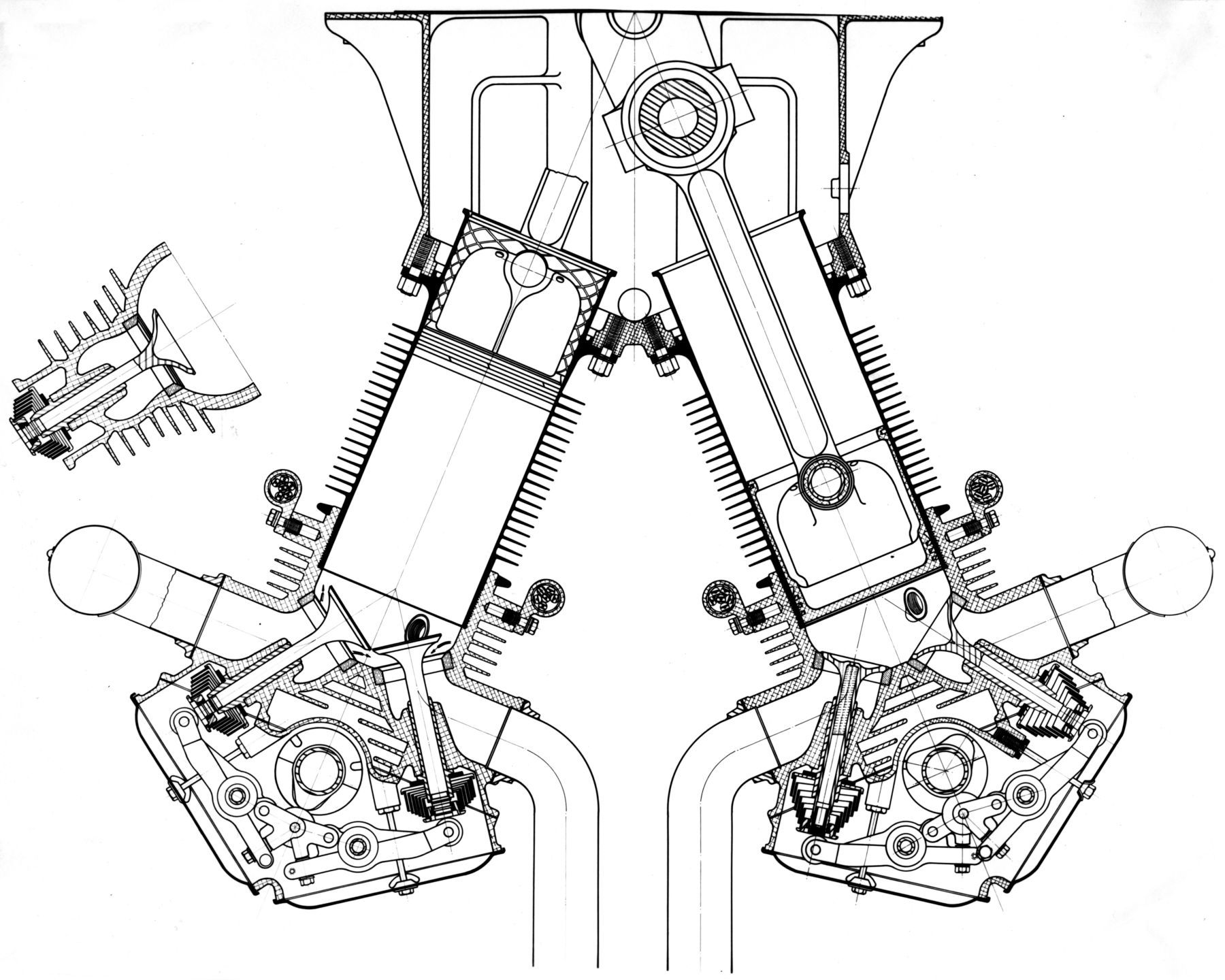
| Liberty Sections (AEE) | ||
When the United States declared war on Germany on 6 April 1917, thereby reversing its previous declaration of neutrality, the country had neither the manpower nor materiel to fight a war. Thus began a rushed attempt to enlarge and equip all military branches. Among the many things desperately needed were aircraft engines. European engine designs were not readily convertible to U.S. production techniques, not to mention that all European engine candidates came with very dear license fees. No high-power (~400 hp) U.S. aircraft engine was in production or contemplated. An Aircraft Production Board was organized on 16 May 1916 to advise the U.S. Army and Navy on aeronautical matters. At the same time, two U.S. engine manufacturers, the Hall-Scott Motor Car Company of Berkley, California and the Packard Motor Car Company of Detroit, Michigan were selling a few engines to the U.S. military.
Jesse G. Vincent, Packard Engineering Vice President, came up with the idea of building an engine series based on common components adaptable to U.S. manufacturing techniques by multiple U.S. manufacturing firms. Originally called U.S.A. Standardized Aircraft Engines, these would become known as Liberty engines. On 28 May 1917, Vincent met with key Aircraft Production Board members and pitched his standard-engine concept. The Board directed Vincent to meet with Elbert J. Hall, Hall-Scott Engineering Vice President and produce a joint report on an engine series that would meet U.S. airplane engine requirements if the U.S. became involved in the War.
Vincent and Hall had never met until the morning of 29 May 1917. They holed up in Suite 201 of the New Willard Hotel in Washington, DC, and by noon had made enough decisions to begin laying out an engine. Hall and Vincent envisioned a common water-cooled cylinder design for use with inline 4- and 6-cylinder engines, as well as a 45° V-8 and a 45° V-12. The 45° V-8 could be produced with an even firing order, but the 45° V-12 did not. Nearly 100 years later, study of the Liberty L-12A crankshaft dynamics suggests that the uneven firing helped mitigate a troublesome crankshaft torsional vibration that may have existed had the V-12 been produced with the usual 60° bank angle. It is doubtful Hall and Vincent made their design choices with this in mind; rather they probably intended that machining operations be similar for both V-8 and V-12 crankcases and wanted a narrower engine to streamline its installation.
During the afternoon of 29 May, Hall and Vincent went out to buy drafting tables and paper; they borrowed drafting instruments from the SAE Washington Chapter's chief. Hall began a longitudinal layout for the U.S.A. 8 while Vincent worked up the transverse section. By noon on 31 May, their report to the Aircraft Production Board was complete and the U.S.A. Standardized Aircraft Engine series was born. The Aircraft Production Board gave its go-ahead to produce six V-8s and five V-12s. Detailed drawings were produced at Packard. Numerous companies across the U.S. produced parts and the first U.S.A. 8 parts kit was delivered to the U.S. Bureau of Standards on 3 July 1917. By 25 July, the engine was running and first flew on 29 August. By now the U.S.A. Standardized Aircraft Engines had acquired the "Liberty" moniker. The first Liberty L-12A was run on 13 Aug 1917, passed its 50-hour test on 26 August and first flew on 19 October. Of the various standardized Liberty designs, only two L-4s, six L-6s and 29 L-8s were built. However, the L-12s were built in gluttonous profusion by Packard, Lincoln, Nordyke & Marmon, Trego, Ford and General Motors Buick Division. In total, 57,962 L-12As were ordered and 20,842 were delivered. WWI ended before very many L-12A-powered aircraft could reach the front. The U.S. military released a glut of engines onto the surplus market. These cheap surplus engines hobbled the U.S. aircraft engine industry for nearly two decades.
 |
 |
 |
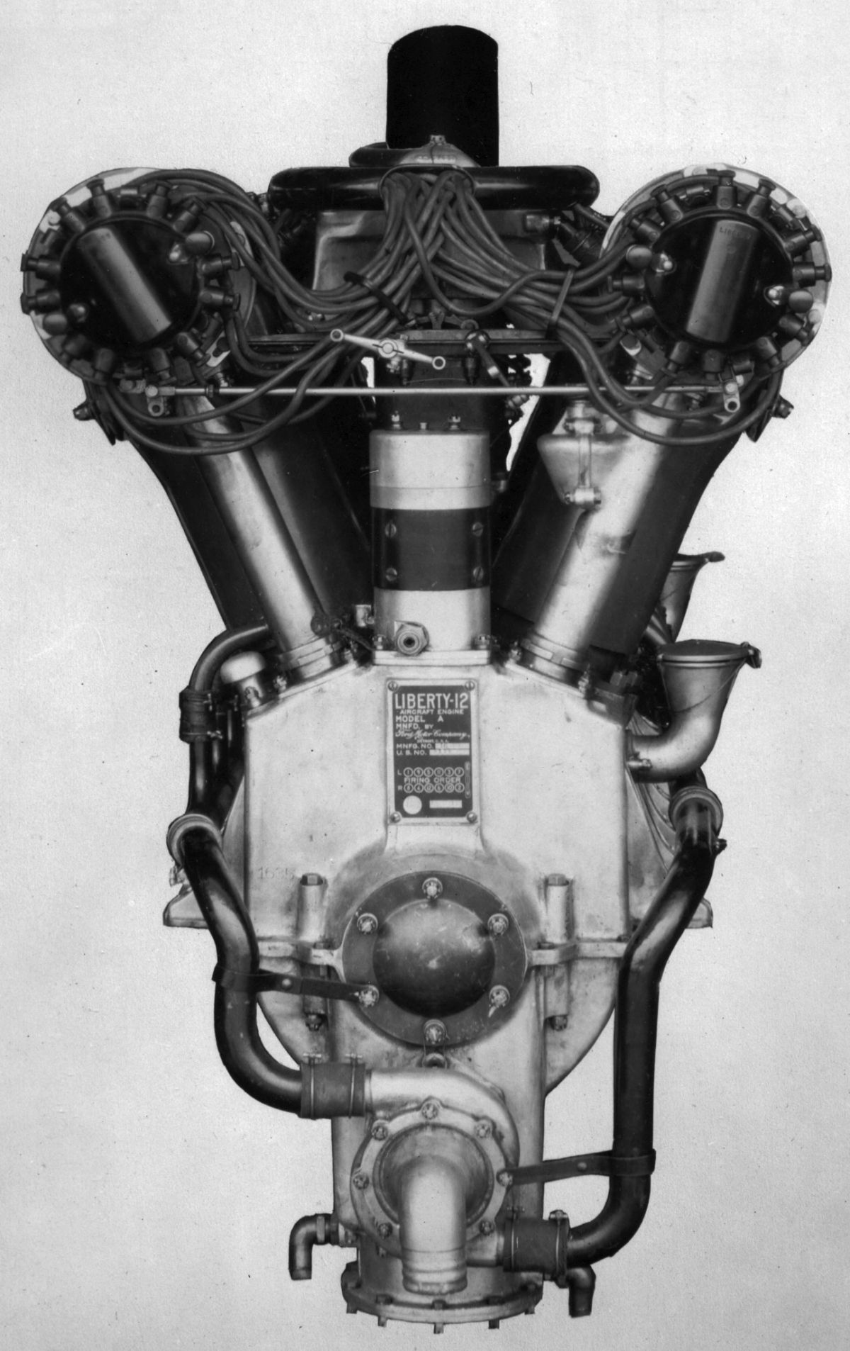 |
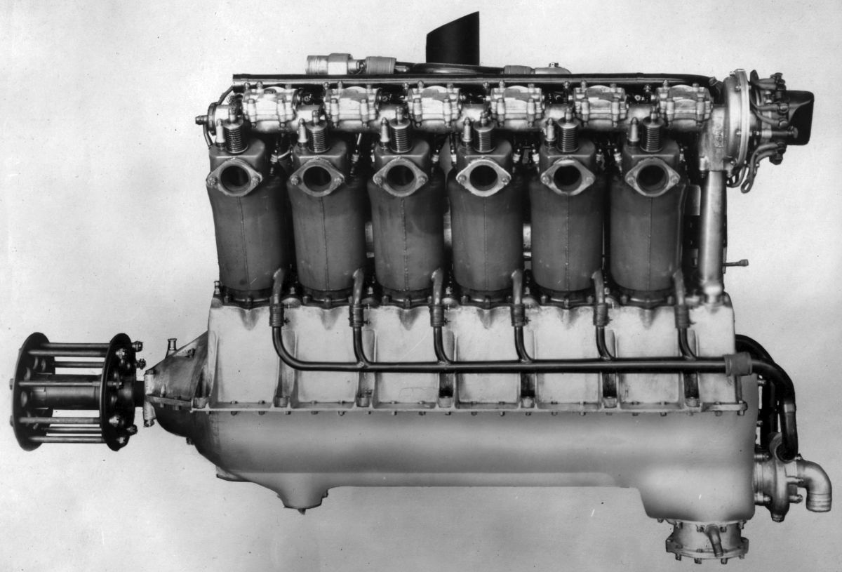
| Liberty L-12A (NARA) | |||
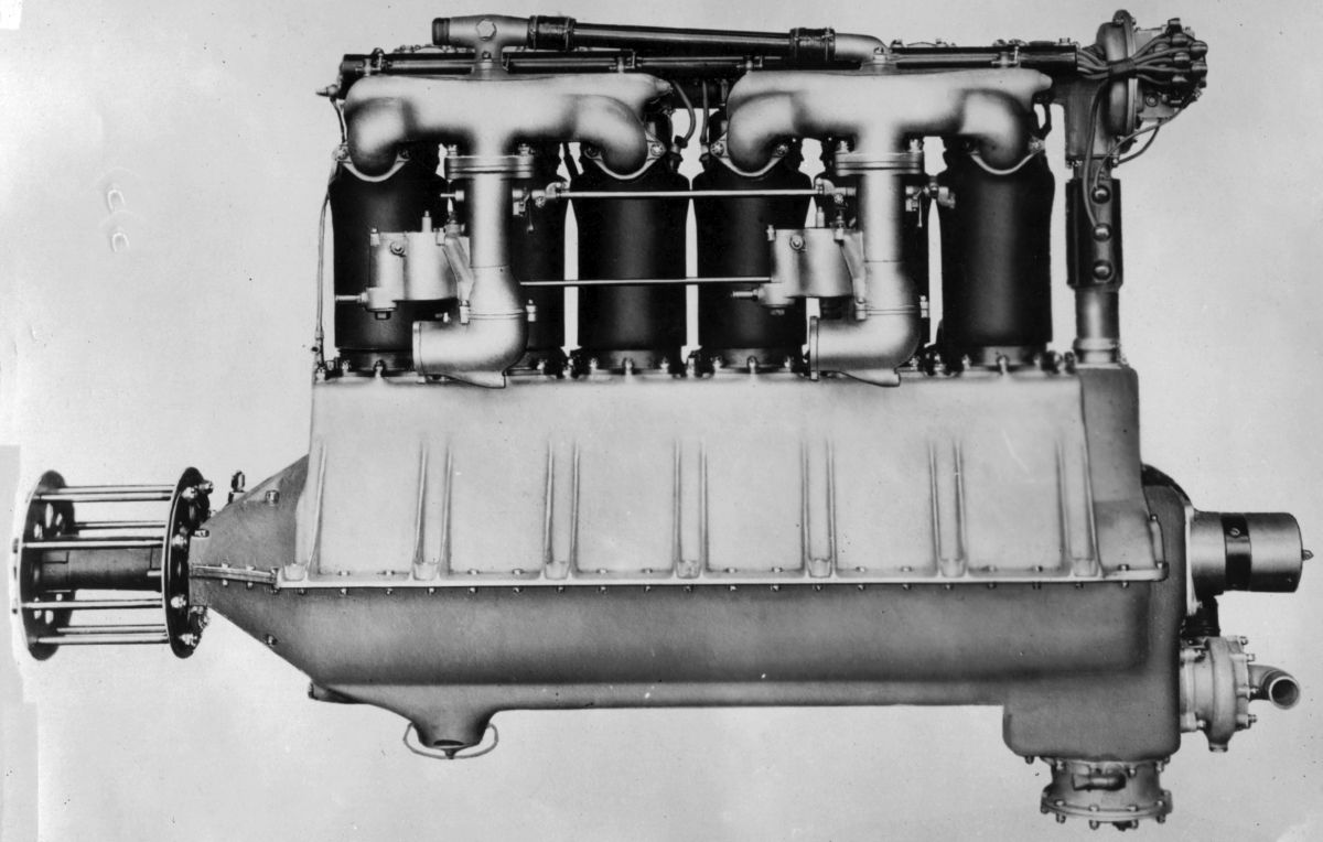
The Liberty L-12A, with its 5.000" (127.0 mm) bore and 7.000" (177.8 mm) stroke displaced 1,649.34 in³ (27.027 l). Army engines had 5.42:1 compression ratios and Navy engines 5.0:1 compression ratios, the difference because Navy engines typically operated at lower altitudes. The Army engine developed 421 hp at 1,700 rpm and 449 hp at 1,940 rpm. At rated power fuel and oil consumption was 0.496 and 0.032 lb/hp/hr. Dry weight was 844 lb (383 kg). The battery, switch, and voltage regulator weighed 13 lb (5.9 kg), and the cooling water weighed 45 lb (20 kg).
The separate forged steel cylinders had pressed-steel water jackets welded in place. The cylinder barrel and combustion chamber were forged as one unit using a swaging process developed by the Ford Motor Company to close the tube end. The valve ports were made from steel forgings and welded to the cylinder head. Inlet water entered the cylinder tangentially and exited through a pipe that extended in toward the exhaust port to receive water at the hottest part of the cylinder; it was perforated to relieve steam pockets. Inlet and exhaust valves, each with a 2.5" (63.5 mm) clear diameter and 30° seat, were inclined to the cylinder vertical. Inlet valve lift was 0.4375" and the exhaust valve lift was 0.375". Inlet valves opened 10° late and closed 45° late; exhaust valves opened 48° late and closed 8° late. Valves were operated by rockers and an overhead camshaft supported in seven split-aluminum bearings. These bearings were stepped in outside diameter to permit sliding the assembly into an aluminum housing, superimposed upon six cylinders and secured by two studs to each one. The valve rockers were an improved Mercedes type designed by Allen Loomis at Packard. Each camshaft was driven by a vertical shaft and bevel gears.
The six-throw un-counterweighted crankshaft was supported in seven plain bearings. The fork-and-blade connecting rods had H-section shanks, and the Lynite (a 95% Al, 5% Cu alloy trademarked by the Aluminum Casting Corporation) pistons were fitted with three compression rings. A dry-sump lubrication system used a gear pump attached to the lower crankcase half to feed oil under pressure to the bearings. Cooling water was circulated by a centrifugal pump with two outlets. Two Zenith U. S. No. 52 duplex carburetors were located in the Vee. The Delco battery type ignition of consisted of a low-voltage generator, an 8V storage battery, and a double distributor system. The distributors were located at the camshaft housing drive ends and the two spark plugs were situated almost vertically in each cylinder head directly underneath the camshaft. housing. L-12As were 67.375" (1,711.3 mm) long, 27" (685.8 mm) wide and 41.5" (1,054.1 mm) high.
The L-12B was essentially an L-12A design fitted with a 1.66:1 ratio epicyclic propeller reduction gear. Allison and Packard built a total of six L-12B engines during WWI; later Allison built 200 L-12Bs for the U.S. Navy. The L-12B was rated 420 hp at 1,750 hp.
The L-12C was another geared engine that used plain spur reduction gears running at a 3:2 ratio. It produced 420 hp at 1,900 rpm and weighed 966 lb (438 kg). After being tested and flown in an experimental airplane the design was abandoned.
A number of other geared L-12 variants emerged, including two-speed, reversing and right-angle for airships. Allison built a gearbox that combined the output of four L-12s to drive a single large propeller.
 |
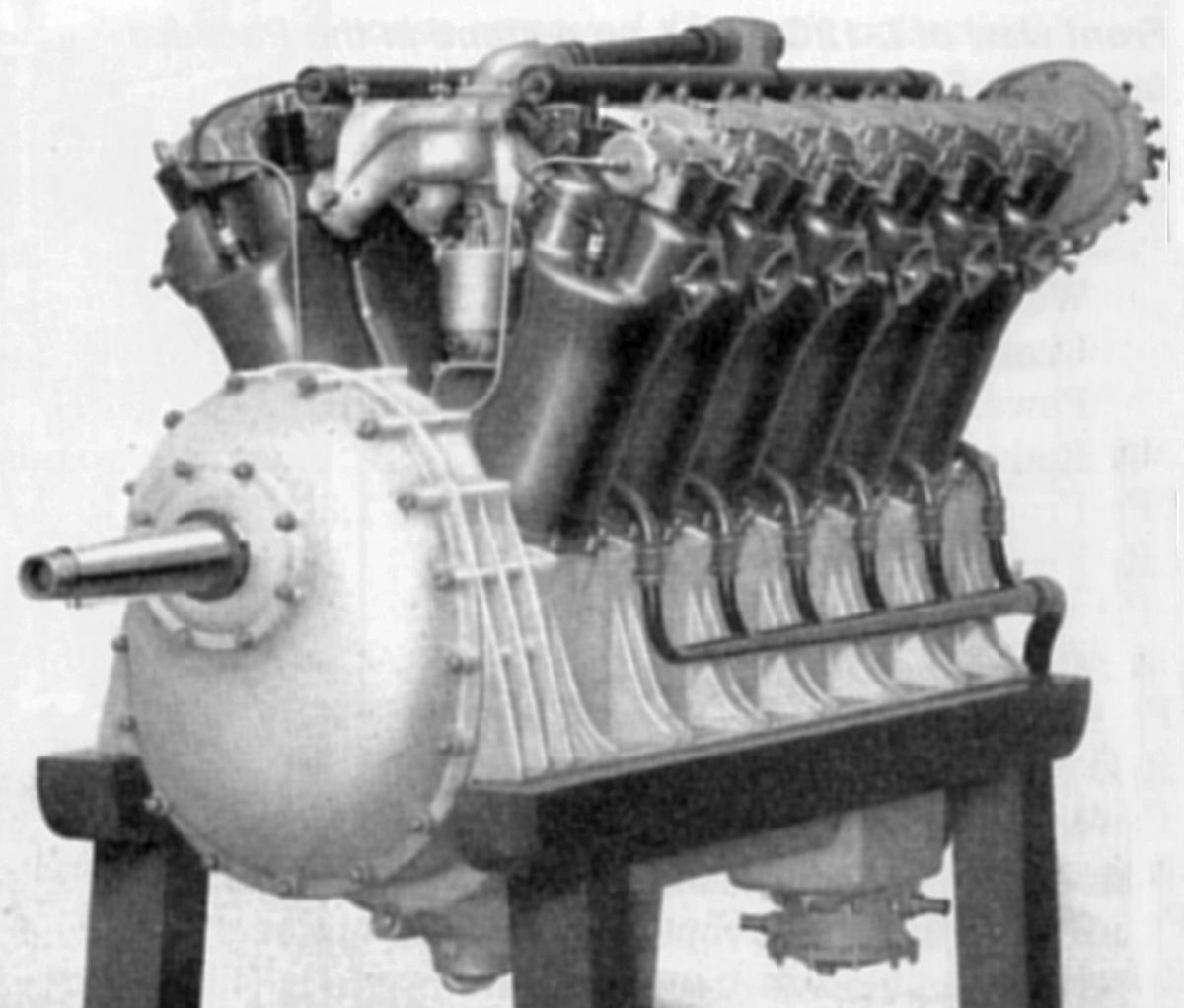 |
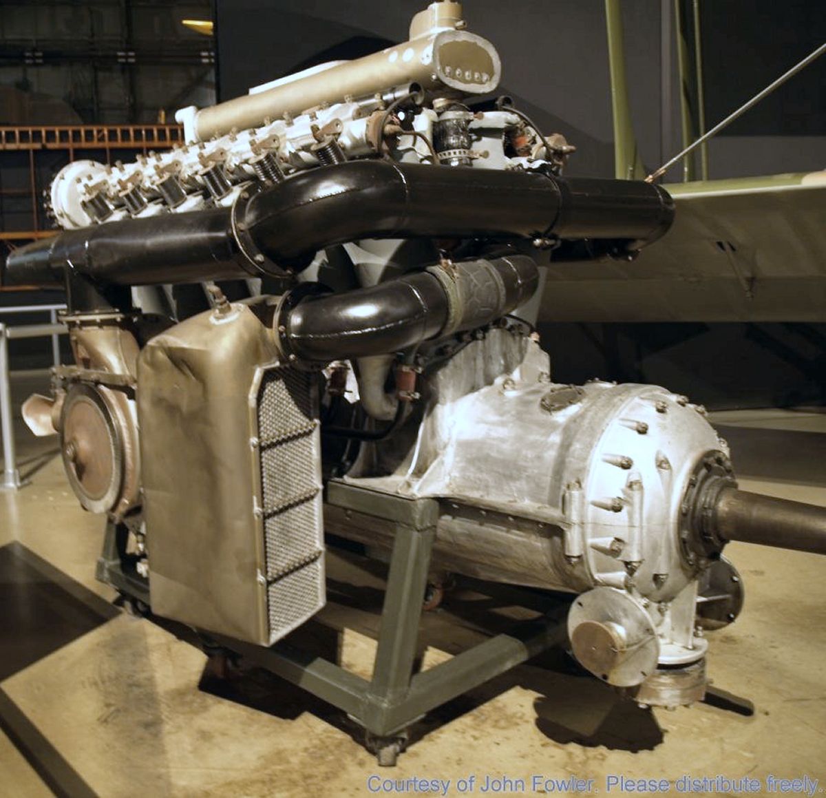
| This unique L-12B at the National Museum of the United States Air Force is fitted with a turbosupercharger. (John Fowler) | The L-12C with Spur Gear Propeller Reduction (NARA) |
 |
 |
 |
 |
 |
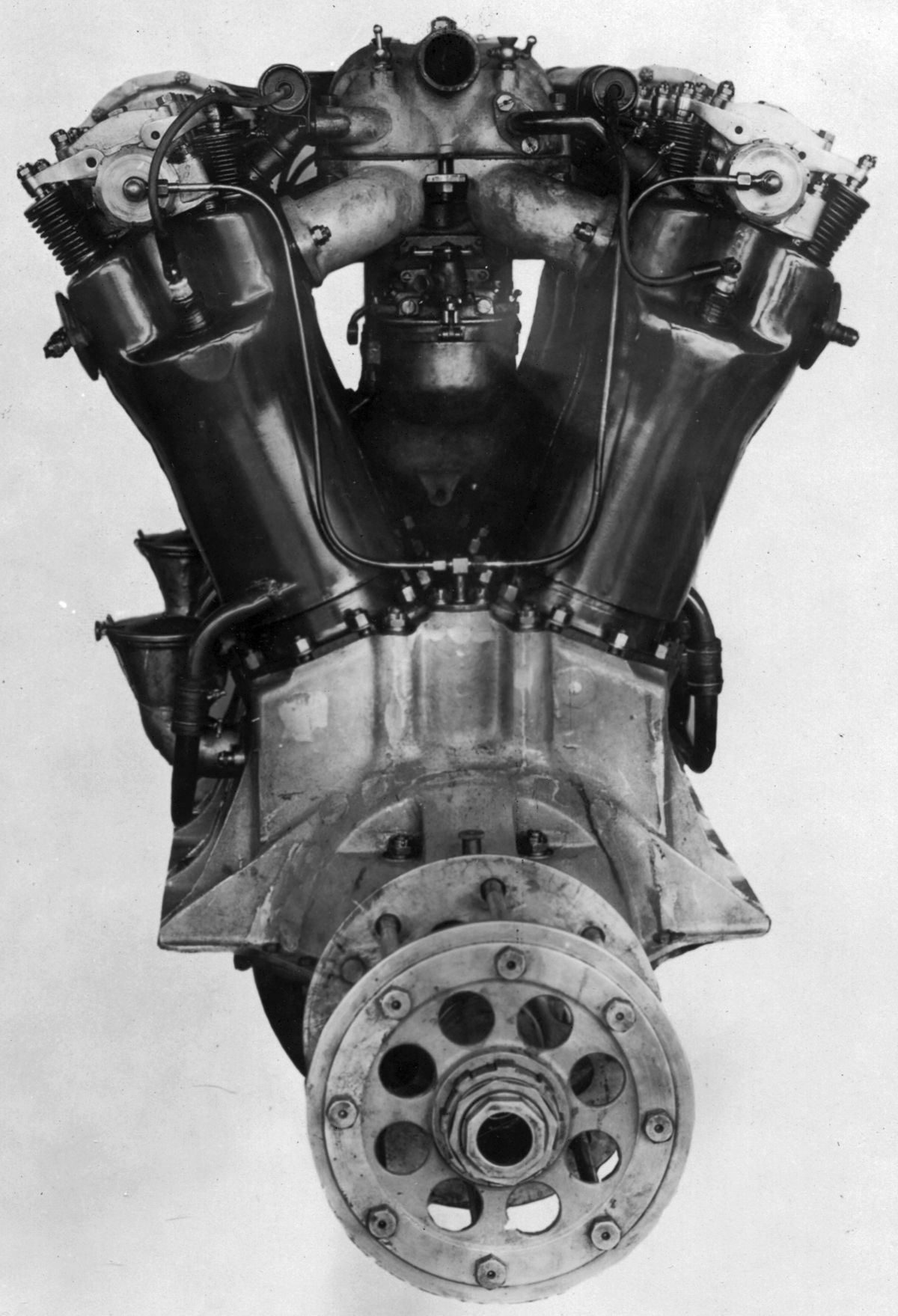
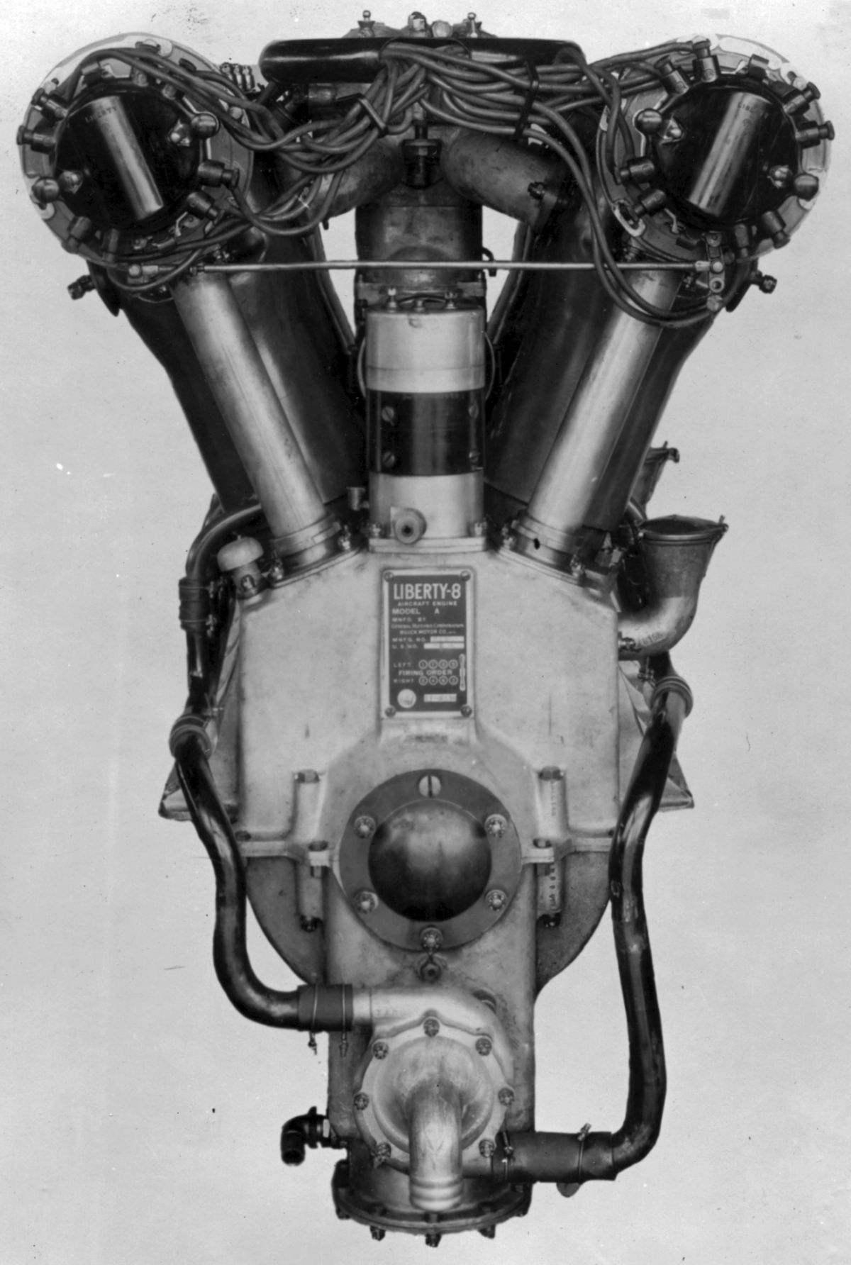
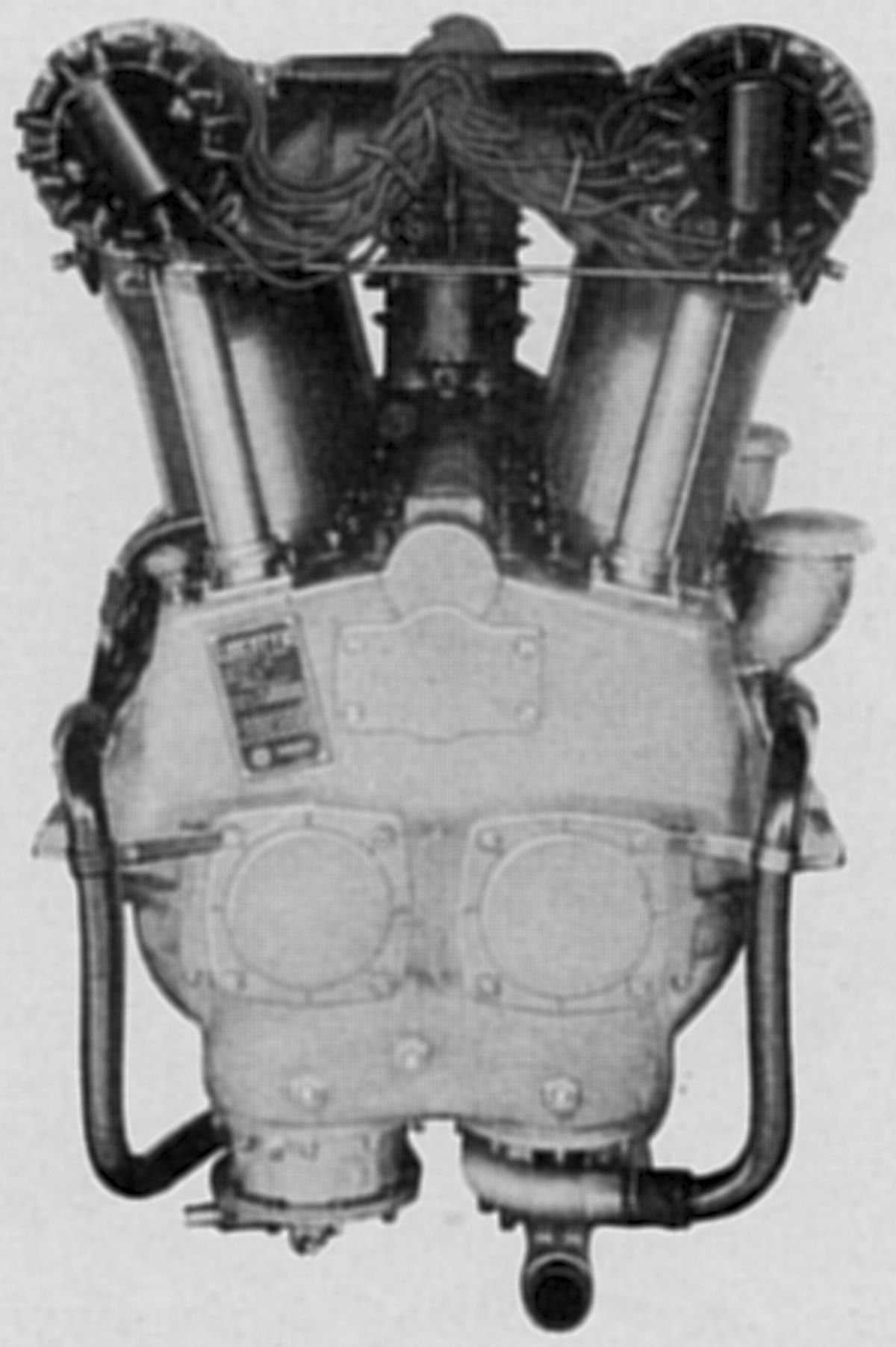
| Liberty L-8 (NARA) | ||||
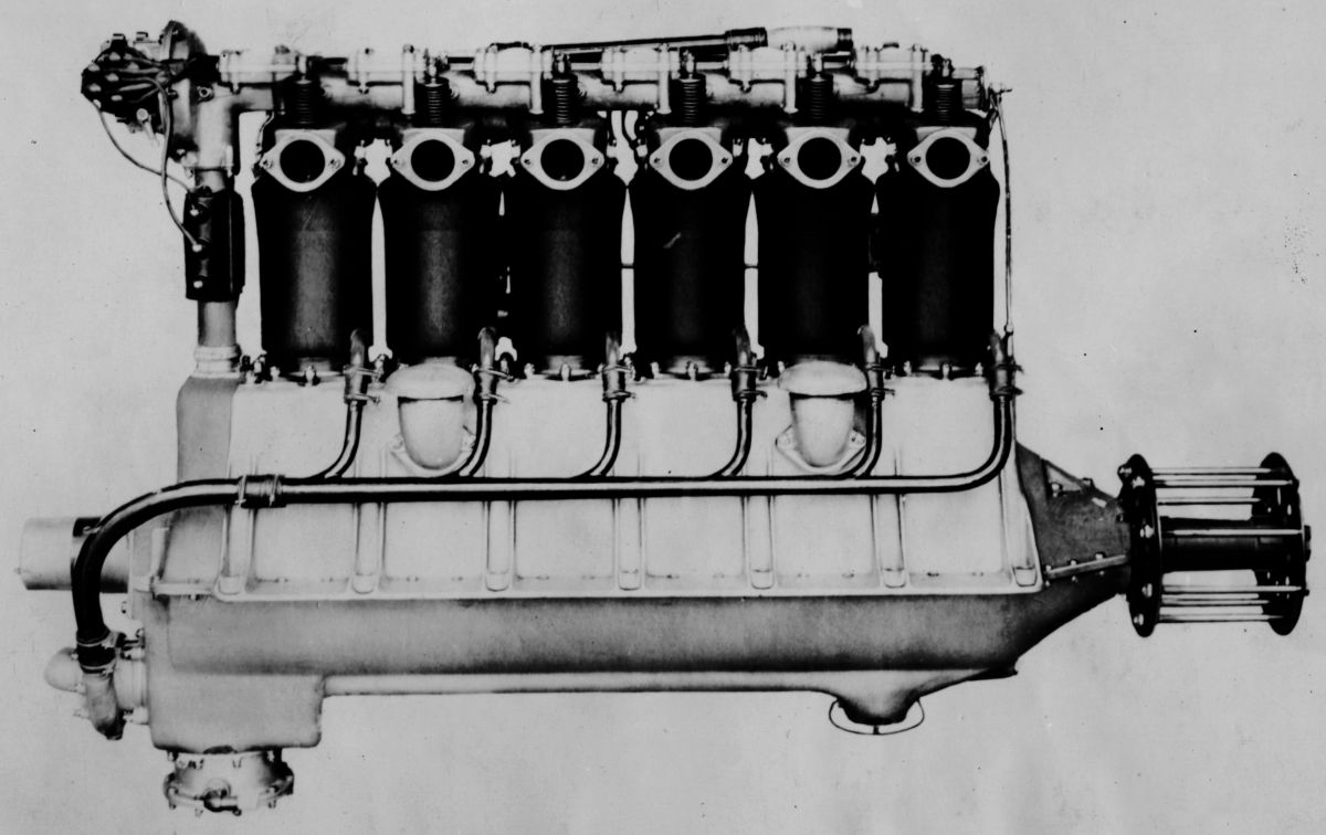
The Liberty L-8 was a 45° V-8 almost identical to the L-12A. It displaced 1,099.55 in³ (18.02 l), developed 290 hp at 1,700 rpm while consuming 0.49 lb/hp/hr fuel and 0.021 lb/hp/hr oil. Its maximum output was 317 hp at 2,000 rpm. It was 57.0" (1,447.8 mm) long, 27" (685.8 mm) wide, 41.5" (1,054.1 mm) high, and weighed 638 lb (289 kg). The cooling water weighed 28 lb (12.7 kg).
 |
 |
 |
||
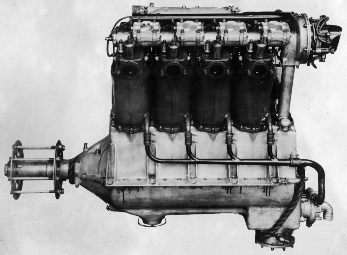
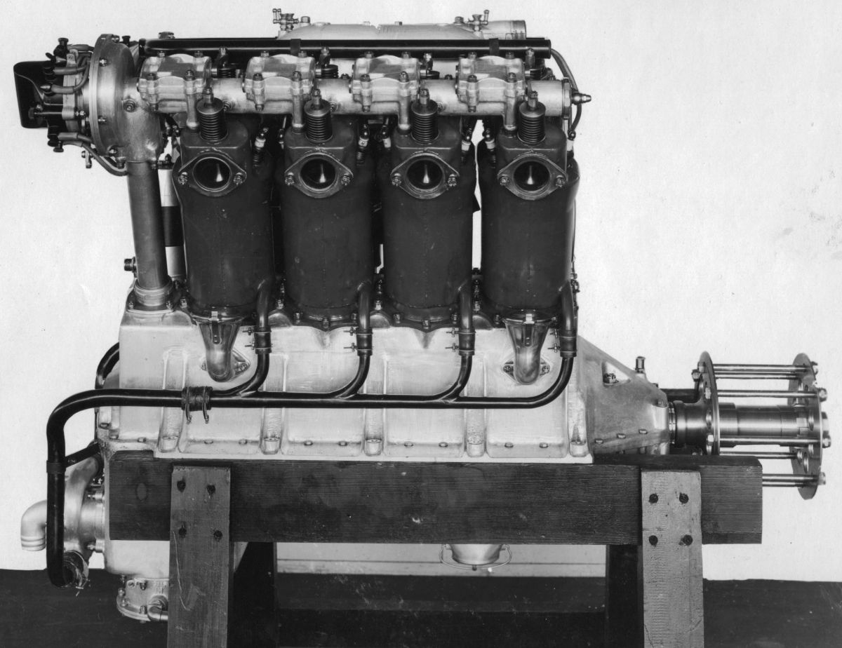
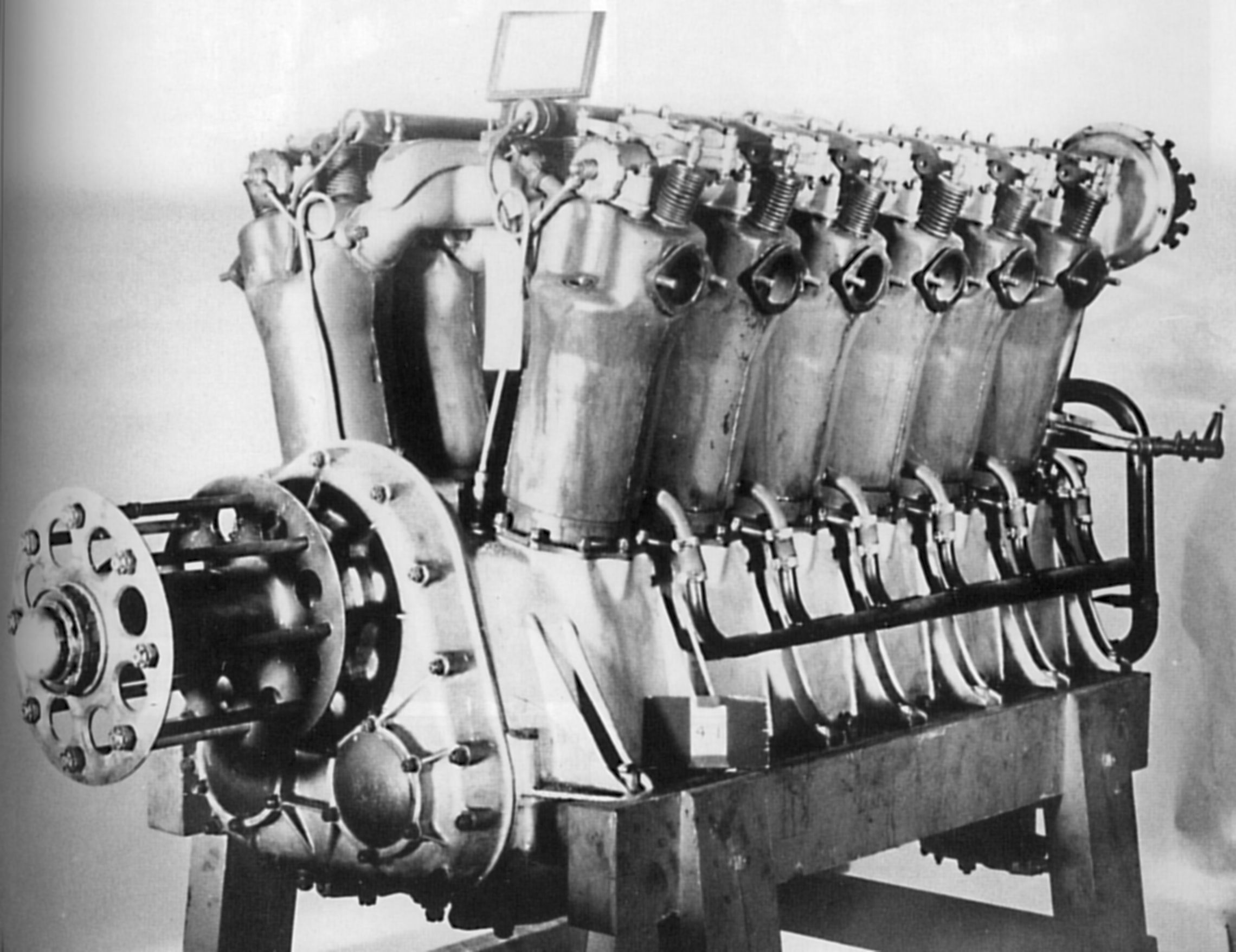
| Liberty L-6 (NARA) | ||||
The Liberty L-6, an inline six, displaced 824.67 in³ (13.514 l), and produced 231 hp at 1,700 rpm and 240 hp at 1,850 rpm. At 1,500 rpm its fuel and oil consumptions were 0.526 and 0.026 lb/hp/hr. It was 68.0" (1,727.2 mm) long, 19.5" (495.3 mm) wide, 43.0" (1,092.2 mm) high and weighed 568 lb (258 kg). The only six L-6 engines built during WWI were manufactured by the Thomas-Morse Aircraft Corporation of Ithaca, New York.
The Liberty L-4 displaced 549.78 in³ (9.01 l) and was rated 100 hp. Only two were built by the Hudson Motor Car Company of Detroit, Michigan, and none are known to have flown.
When WWI ended, the U.S. Government had a sufficient stock of L-12s to meet the demand for several years at peace-time consumption rate. These engines were prepared for storage and placed in various Government storage depots. Further development of this engine during the years immediately following WWI made it advisable to rebuild, with changes, all engines removed from storage for service use. These alterations included installing stub-tooth gears and steel-backed main and connecting rod bearings. Contracts covering engine rebuilds were filled by the Steel Products Engineering Co. of Springfield, Ohio and the Allison Engineering Co. of Indianapolis, Indiana.
In February 1934, the U.S. Army ordered that no more Liberty engines were to be used in service airplanes, thus marking the end of the Liberty era. However, the engines soldiered on in barnstormers' aircraft, propelling boats, automobiles and tanks, driving pumps and fans, and in numerous other applications where cheap and potentially powerful engines could be applied.
Post-War Experimental Liberty Engines
Perhaps the Liberty L-12s greatest legacy was its prolific use as experimental test mules. L-12s were the subject of nearly every conceivable modification and innovation. This included air-cooling, inverted configurations and an X-24 version.
During 1923, several L-12s were converted by the U.S. Army Air Service Engineering Division at McCook Field, Dayton, Ohio for inverted installation. The improvement, not only in the airplane and its performance, but in the actual engine output, resulted in improved lubrication and cooling system designs for this conversion.
Packard built the L-12E, a two-crankshaft 12-cylinder engine with its two cylinder banks canted outward at 22.5° to vertical and the crankshafts geared together to a common hollow propeller shaft that allowed a cannon placed behind the engine to fire through the propeller shaft; this concept was never fully developed. It was rated 400 hp at 1,700 rpm and weighed 1,136 lb (515 kg).
L-12s were used for the U.S. Army Air Service's early experiments with engine-driven superchargers and exhaust-driven turbosuperchargers. An L-12 cylinder was the basis for Sam Heron's experiments with highly-supercharged, high-speed, high-output cylinders that the Air Service called its Hyper cylinder and which led to the last generation of high-power liquid-cooled engines.
 |
 |
 |
 |
 |
|
| This Engineering Division-developed Series 3 inverted air-cooled L-12 was fitted with a 5:3 epicyclic reduction gear and low-pressure supercharger. It developed 435 hp at 1,900 rpm with a 0.55 lb/hp/hr fuel consumption. (NARA) | Liberty L-12E, 5:3 Propeller Reduction Gear Ratio (NARA) | Packard’s Experimental X-24 (NARA) | |||
References
Angle, Glenn D, ed. Aerosphere 1939 (New York, New York: Aircraft Publications, 1940).
Anble, Glenn D, ed. Airplane Engine Encyclopedia (Dayton, Ohio: Otterbein Press, 1921).
Le RhÔne 9C Manuals
Moteurs de légende: Le Rhône
Neal, Robert J. A Technical and Operational History of the Liberty Engine (North Branch, Minnesota: Specialty Press, 2009)
Image Sources: A39 = Aerosphere 1939; AEE = Airplane Engine Encyclopedia; Flt = Flight Magazine; LeR = Le RhÔne Manuals; NARA = U.S. National Archives and Records Administration; UKNA = United Kingdom National Archives.
Send mail to
![]() with questions or comments about this web site.
with questions or comments about this web site.
![]()